EP2511124A1 - Control apparatus and control method for electrically driven vehicle - Google Patents
Control apparatus and control method for electrically driven vehicle Download PDFInfo
- Publication number
- EP2511124A1 EP2511124A1 EP10835934A EP10835934A EP2511124A1 EP 2511124 A1 EP2511124 A1 EP 2511124A1 EP 10835934 A EP10835934 A EP 10835934A EP 10835934 A EP10835934 A EP 10835934A EP 2511124 A1 EP2511124 A1 EP 2511124A1
- Authority
- EP
- European Patent Office
- Prior art keywords
- drive
- revolutions
- steering angle
- wheel
- wheels
- Prior art date
- Legal status (The legal status is an assumption and is not a legal conclusion. Google has not performed a legal analysis and makes no representation as to the accuracy of the status listed.)
- Withdrawn
Links
- 238000000034 method Methods 0.000 title claims description 17
- 238000001514 detection method Methods 0.000 claims description 3
- 238000012937 correction Methods 0.000 description 13
- 230000007935 neutral effect Effects 0.000 description 5
- 230000001419 dependent effect Effects 0.000 description 3
- 230000000712 assembly Effects 0.000 description 2
- 238000000429 assembly Methods 0.000 description 2
- 238000010276 construction Methods 0.000 description 2
- 238000010586 diagram Methods 0.000 description 2
- 238000012986 modification Methods 0.000 description 2
- 230000004048 modification Effects 0.000 description 2
- 230000003247 decreasing effect Effects 0.000 description 1
- 230000001360 synchronised effect Effects 0.000 description 1
Images

Classifications
-
- B—PERFORMING OPERATIONS; TRANSPORTING
- B60—VEHICLES IN GENERAL
- B60L—PROPULSION OF ELECTRICALLY-PROPELLED VEHICLES; SUPPLYING ELECTRIC POWER FOR AUXILIARY EQUIPMENT OF ELECTRICALLY-PROPELLED VEHICLES; ELECTRODYNAMIC BRAKE SYSTEMS FOR VEHICLES IN GENERAL; MAGNETIC SUSPENSION OR LEVITATION FOR VEHICLES; MONITORING OPERATING VARIABLES OF ELECTRICALLY-PROPELLED VEHICLES; ELECTRIC SAFETY DEVICES FOR ELECTRICALLY-PROPELLED VEHICLES
- B60L15/00—Methods, circuits, or devices for controlling the traction-motor speed of electrically-propelled vehicles
- B60L15/20—Methods, circuits, or devices for controlling the traction-motor speed of electrically-propelled vehicles for control of the vehicle or its driving motor to achieve a desired performance, e.g. speed, torque, programmed variation of speed
-
- B—PERFORMING OPERATIONS; TRANSPORTING
- B60—VEHICLES IN GENERAL
- B60K—ARRANGEMENT OR MOUNTING OF PROPULSION UNITS OR OF TRANSMISSIONS IN VEHICLES; ARRANGEMENT OR MOUNTING OF PLURAL DIVERSE PRIME-MOVERS IN VEHICLES; AUXILIARY DRIVES FOR VEHICLES; INSTRUMENTATION OR DASHBOARDS FOR VEHICLES; ARRANGEMENTS IN CONNECTION WITH COOLING, AIR INTAKE, GAS EXHAUST OR FUEL SUPPLY OF PROPULSION UNITS IN VEHICLES
- B60K7/00—Disposition of motor in, or adjacent to, traction wheel
-
- B—PERFORMING OPERATIONS; TRANSPORTING
- B60—VEHICLES IN GENERAL
- B60K—ARRANGEMENT OR MOUNTING OF PROPULSION UNITS OR OF TRANSMISSIONS IN VEHICLES; ARRANGEMENT OR MOUNTING OF PLURAL DIVERSE PRIME-MOVERS IN VEHICLES; AUXILIARY DRIVES FOR VEHICLES; INSTRUMENTATION OR DASHBOARDS FOR VEHICLES; ARRANGEMENTS IN CONNECTION WITH COOLING, AIR INTAKE, GAS EXHAUST OR FUEL SUPPLY OF PROPULSION UNITS IN VEHICLES
- B60K7/00—Disposition of motor in, or adjacent to, traction wheel
- B60K7/0007—Disposition of motor in, or adjacent to, traction wheel the motor being electric
-
- B—PERFORMING OPERATIONS; TRANSPORTING
- B60—VEHICLES IN GENERAL
- B60L—PROPULSION OF ELECTRICALLY-PROPELLED VEHICLES; SUPPLYING ELECTRIC POWER FOR AUXILIARY EQUIPMENT OF ELECTRICALLY-PROPELLED VEHICLES; ELECTRODYNAMIC BRAKE SYSTEMS FOR VEHICLES IN GENERAL; MAGNETIC SUSPENSION OR LEVITATION FOR VEHICLES; MONITORING OPERATING VARIABLES OF ELECTRICALLY-PROPELLED VEHICLES; ELECTRIC SAFETY DEVICES FOR ELECTRICALLY-PROPELLED VEHICLES
- B60L15/00—Methods, circuits, or devices for controlling the traction-motor speed of electrically-propelled vehicles
- B60L15/20—Methods, circuits, or devices for controlling the traction-motor speed of electrically-propelled vehicles for control of the vehicle or its driving motor to achieve a desired performance, e.g. speed, torque, programmed variation of speed
- B60L15/2036—Electric differentials, e.g. for supporting steering vehicles
-
- B—PERFORMING OPERATIONS; TRANSPORTING
- B60—VEHICLES IN GENERAL
- B60W—CONJOINT CONTROL OF VEHICLE SUB-UNITS OF DIFFERENT TYPE OR DIFFERENT FUNCTION; CONTROL SYSTEMS SPECIALLY ADAPTED FOR HYBRID VEHICLES; ROAD VEHICLE DRIVE CONTROL SYSTEMS FOR PURPOSES NOT RELATED TO THE CONTROL OF A PARTICULAR SUB-UNIT
- B60W10/00—Conjoint control of vehicle sub-units of different type or different function
- B60W10/04—Conjoint control of vehicle sub-units of different type or different function including control of propulsion units
- B60W10/08—Conjoint control of vehicle sub-units of different type or different function including control of propulsion units including control of electric propulsion units, e.g. motors or generators
-
- B—PERFORMING OPERATIONS; TRANSPORTING
- B60—VEHICLES IN GENERAL
- B60W—CONJOINT CONTROL OF VEHICLE SUB-UNITS OF DIFFERENT TYPE OR DIFFERENT FUNCTION; CONTROL SYSTEMS SPECIALLY ADAPTED FOR HYBRID VEHICLES; ROAD VEHICLE DRIVE CONTROL SYSTEMS FOR PURPOSES NOT RELATED TO THE CONTROL OF A PARTICULAR SUB-UNIT
- B60W30/00—Purposes of road vehicle drive control systems not related to the control of a particular sub-unit, e.g. of systems using conjoint control of vehicle sub-units
- B60W30/18—Propelling the vehicle
- B60W30/18009—Propelling the vehicle related to particular drive situations
- B60W30/18145—Cornering
-
- B—PERFORMING OPERATIONS; TRANSPORTING
- B60—VEHICLES IN GENERAL
- B60K—ARRANGEMENT OR MOUNTING OF PROPULSION UNITS OR OF TRANSMISSIONS IN VEHICLES; ARRANGEMENT OR MOUNTING OF PLURAL DIVERSE PRIME-MOVERS IN VEHICLES; AUXILIARY DRIVES FOR VEHICLES; INSTRUMENTATION OR DASHBOARDS FOR VEHICLES; ARRANGEMENTS IN CONNECTION WITH COOLING, AIR INTAKE, GAS EXHAUST OR FUEL SUPPLY OF PROPULSION UNITS IN VEHICLES
- B60K1/00—Arrangement or mounting of electrical propulsion units
- B60K1/02—Arrangement or mounting of electrical propulsion units comprising more than one electric motor
-
- B—PERFORMING OPERATIONS; TRANSPORTING
- B60—VEHICLES IN GENERAL
- B60K—ARRANGEMENT OR MOUNTING OF PROPULSION UNITS OR OF TRANSMISSIONS IN VEHICLES; ARRANGEMENT OR MOUNTING OF PLURAL DIVERSE PRIME-MOVERS IN VEHICLES; AUXILIARY DRIVES FOR VEHICLES; INSTRUMENTATION OR DASHBOARDS FOR VEHICLES; ARRANGEMENTS IN CONNECTION WITH COOLING, AIR INTAKE, GAS EXHAUST OR FUEL SUPPLY OF PROPULSION UNITS IN VEHICLES
- B60K7/00—Disposition of motor in, or adjacent to, traction wheel
- B60K2007/0038—Disposition of motor in, or adjacent to, traction wheel the motor moving together with the wheel axle
-
- B—PERFORMING OPERATIONS; TRANSPORTING
- B60—VEHICLES IN GENERAL
- B60L—PROPULSION OF ELECTRICALLY-PROPELLED VEHICLES; SUPPLYING ELECTRIC POWER FOR AUXILIARY EQUIPMENT OF ELECTRICALLY-PROPELLED VEHICLES; ELECTRODYNAMIC BRAKE SYSTEMS FOR VEHICLES IN GENERAL; MAGNETIC SUSPENSION OR LEVITATION FOR VEHICLES; MONITORING OPERATING VARIABLES OF ELECTRICALLY-PROPELLED VEHICLES; ELECTRIC SAFETY DEVICES FOR ELECTRICALLY-PROPELLED VEHICLES
- B60L2220/00—Electrical machine types; Structures or applications thereof
- B60L2220/40—Electrical machine applications
- B60L2220/44—Wheel Hub motors, i.e. integrated in the wheel hub
-
- B—PERFORMING OPERATIONS; TRANSPORTING
- B60—VEHICLES IN GENERAL
- B60L—PROPULSION OF ELECTRICALLY-PROPELLED VEHICLES; SUPPLYING ELECTRIC POWER FOR AUXILIARY EQUIPMENT OF ELECTRICALLY-PROPELLED VEHICLES; ELECTRODYNAMIC BRAKE SYSTEMS FOR VEHICLES IN GENERAL; MAGNETIC SUSPENSION OR LEVITATION FOR VEHICLES; MONITORING OPERATING VARIABLES OF ELECTRICALLY-PROPELLED VEHICLES; ELECTRIC SAFETY DEVICES FOR ELECTRICALLY-PROPELLED VEHICLES
- B60L2240/00—Control parameters of input or output; Target parameters
- B60L2240/10—Vehicle control parameters
- B60L2240/24—Steering angle
-
- B—PERFORMING OPERATIONS; TRANSPORTING
- B60—VEHICLES IN GENERAL
- B60L—PROPULSION OF ELECTRICALLY-PROPELLED VEHICLES; SUPPLYING ELECTRIC POWER FOR AUXILIARY EQUIPMENT OF ELECTRICALLY-PROPELLED VEHICLES; ELECTRODYNAMIC BRAKE SYSTEMS FOR VEHICLES IN GENERAL; MAGNETIC SUSPENSION OR LEVITATION FOR VEHICLES; MONITORING OPERATING VARIABLES OF ELECTRICALLY-PROPELLED VEHICLES; ELECTRIC SAFETY DEVICES FOR ELECTRICALLY-PROPELLED VEHICLES
- B60L2240/00—Control parameters of input or output; Target parameters
- B60L2240/40—Drive Train control parameters
- B60L2240/42—Drive Train control parameters related to electric machines
- B60L2240/423—Torque
-
- B—PERFORMING OPERATIONS; TRANSPORTING
- B60—VEHICLES IN GENERAL
- B60T—VEHICLE BRAKE CONTROL SYSTEMS OR PARTS THEREOF; BRAKE CONTROL SYSTEMS OR PARTS THEREOF, IN GENERAL; ARRANGEMENT OF BRAKING ELEMENTS ON VEHICLES IN GENERAL; PORTABLE DEVICES FOR PREVENTING UNWANTED MOVEMENT OF VEHICLES; VEHICLE MODIFICATIONS TO FACILITATE COOLING OF BRAKES
- B60T2240/00—Monitoring, detecting wheel/tyre behaviour; counteracting thereof
- B60T2240/07—Tyre tolerance compensation
-
- B—PERFORMING OPERATIONS; TRANSPORTING
- B60—VEHICLES IN GENERAL
- B60W—CONJOINT CONTROL OF VEHICLE SUB-UNITS OF DIFFERENT TYPE OR DIFFERENT FUNCTION; CONTROL SYSTEMS SPECIALLY ADAPTED FOR HYBRID VEHICLES; ROAD VEHICLE DRIVE CONTROL SYSTEMS FOR PURPOSES NOT RELATED TO THE CONTROL OF A PARTICULAR SUB-UNIT
- B60W2510/00—Input parameters relating to a particular sub-units
- B60W2510/08—Electric propulsion units
- B60W2510/083—Torque
-
- B—PERFORMING OPERATIONS; TRANSPORTING
- B60—VEHICLES IN GENERAL
- B60W—CONJOINT CONTROL OF VEHICLE SUB-UNITS OF DIFFERENT TYPE OR DIFFERENT FUNCTION; CONTROL SYSTEMS SPECIALLY ADAPTED FOR HYBRID VEHICLES; ROAD VEHICLE DRIVE CONTROL SYSTEMS FOR PURPOSES NOT RELATED TO THE CONTROL OF A PARTICULAR SUB-UNIT
- B60W2540/00—Input parameters relating to occupants
- B60W2540/18—Steering angle
-
- Y—GENERAL TAGGING OF NEW TECHNOLOGICAL DEVELOPMENTS; GENERAL TAGGING OF CROSS-SECTIONAL TECHNOLOGIES SPANNING OVER SEVERAL SECTIONS OF THE IPC; TECHNICAL SUBJECTS COVERED BY FORMER USPC CROSS-REFERENCE ART COLLECTIONS [XRACs] AND DIGESTS
- Y02—TECHNOLOGIES OR APPLICATIONS FOR MITIGATION OR ADAPTATION AGAINST CLIMATE CHANGE
- Y02T—CLIMATE CHANGE MITIGATION TECHNOLOGIES RELATED TO TRANSPORTATION
- Y02T10/00—Road transport of goods or passengers
- Y02T10/60—Other road transportation technologies with climate change mitigation effect
- Y02T10/64—Electric machine technologies in electromobility
-
- Y—GENERAL TAGGING OF NEW TECHNOLOGICAL DEVELOPMENTS; GENERAL TAGGING OF CROSS-SECTIONAL TECHNOLOGIES SPANNING OVER SEVERAL SECTIONS OF THE IPC; TECHNICAL SUBJECTS COVERED BY FORMER USPC CROSS-REFERENCE ART COLLECTIONS [XRACs] AND DIGESTS
- Y02—TECHNOLOGIES OR APPLICATIONS FOR MITIGATION OR ADAPTATION AGAINST CLIMATE CHANGE
- Y02T—CLIMATE CHANGE MITIGATION TECHNOLOGIES RELATED TO TRANSPORTATION
- Y02T10/00—Road transport of goods or passengers
- Y02T10/60—Other road transportation technologies with climate change mitigation effect
- Y02T10/72—Electric energy management in electromobility
Definitions
- the present invention relates to the control of an electrically driven vehicle such as, for example, an automotive vehicle of a kind having left and right, independent drive motors.
- the electric motorcar now attracting public attentions is considered a high performance vehicle as it makes use of left and right electric motors such as, for example, in-wheel motors that can be controlled independently from each other.
- the electric motors employed are driven according to either a torque control scheme, that is, a scheme in which the electric current to be supplied to each of the electric motors is controlled, or of a scheme in which the number of revolutions of each of the electric motors is controlled.
- the drive wheels themselves tend to generate a turning force or a slewing force in the event that because of, for example, a change in tire pneumatic pressure, the effective radius differs between those drive wheels.
- the patent document 1 listed below addresses correction of a difference in driving force brought about by the difference in tire diameters and discloses a control method utilizing threshold values to refrain from exceeding the limit. In this control method, the difference in driving forces is to a certain extent permissible.
- Patent Document 1 JP Laid-open Patent Publication No. 2006-240402
- the correction of the difference in driving force resulting from the difference of the tire diameters which is disclosed in the patent document 1 listed above, is a control method in which the threshold values are utilized to avoid a possible surpass over the limits and, therefore, the difference in driving forces is permitted to a certain extent. For this reason, an improvement in vehicle traveling stability is insufficient.
- an object of the present invention is to provide a control device for an electrically powered vehicle of a type, in which even when the effective radii differ between left and right vehicle wheels because of a change in, for example, a tire pneumatic pressure in one or both of the vehicle wheels, the difference in driving forces between the left and right vehicle drive wheels can be zeroed to suppress generation of the turning force to thereby improve the vehicle traveling stability, and, also, to provide a method of so controlling in the electrically powered vehicle.
- the present invention in accordance with one aspect thereof provides a control device for an electrically powered vehicle including a plurality of drive wheels capable of respectively performing left and right drives, which are independent from each other, and electric drive motors for driving those drive wheels, that is, a control device for an electrically powered vehicle of a type employing a plurality of drive wheels, drives of those wheels being performed separately and independently from each other, and electric drive motors for driving left and right drive wheels, respectively, separately and independently from each other.
- the control device for the electrically powered vehicle referred to above includes a steering angle detector for detecting the steering angle, which is the angle of turn of a steering wheel; a rotational number detector for detecting the number of revolutions per unitary time of each of the drive wheels; an electric drive motor current detector for detecting an electric drive motor current, which is a drive current applied to an electric drive motor for each of the drive wheels; a drive command output section capable of outputting a command value in accordance with an amount of actuation of an accelerator pedal; and a correcting section for correcting the command value of an electric current value or the number of revolutions that is inputted from the drive command output section so that the corrected command value is outputted to the drive circuit for the electric drive motor for each of the drive wheels.
- the correcting section referred to above is inputted with the steering angle detected by the steering angle detector, the number of revolutions of each of the drive wheels detected by the rotational number detector and the electric drive motor current detected by the electric drive motor current detector and makes use of the steering angle as measured with respect to a traveling direction and is operable to correct the command value in accordance with a rule stipulated so that the relation between the corrected command values to be outputted to the respective drive circuits for the left and right drive wheels is such that rather than the relation between the command values before being corrected, a turning force induced in the electrically powered vehicle because of the difference in effective radius of the drive wheels can be suppressed.
- the correcting section referred to above makes use of the steering angle as measured with respect to a traveling direction and is operable to correct the command value of the electric current or the number of revolutions in accordance with a rule stipulated so that the relation between the corrected command values to be outputted to the respective drive circuits for the left and right drive wheels is such that rather than the relation between the command values before being corrected, a turning force induced in the electrically powered vehicle because of the difference in effective radius of the drive wheels can be suppressed.
- the rule stipulated for the correcting section depends on whether the drive command output section is capable of performing the torque control or whether the drive command output section is capable of performing the rotational number control.
- the wording "the steering angle is zero" is to be construed as encompassing a range in which steering can be regarded as indicative of a straight forward travel.
- one of the wheels having a relatively small effective radius than the other tends to give rise to a large driving force, which in turn leads to a generation of the turning force.
- the number of wheel revolutions tends to become high even during the straight forward travel of the electrically powered vehicle as compared with a wheel having a normal size. For this reason, in the event that the difference in number of revolutions occurs between the left and right wheels when the electrically powered vehicle is driven straight forwards with no steering wheel being turned, it is determined that reduction of the effective radius of one of the wheels is caused by a change of the tire pneumatic pressure or the like.
- the torque to be applied to the electric drive motor for the wheel with the high number of revolutions is corrected so as to be decreased. Accordingly, it is possible to suppress an undesirable generation of the turning force caused by the difference between the respective effective radii of the left and right drive wheels.
- the stipulated rule followed by the correcting section may have a content which is such that when the steering angle detected by the steering angle detector indicates a turning condition, the radius of turn of the electrically powered vehicle and the respective theoretical numbers of revolutions of the left and right drive wheels and the rotation ratios of those numbers of revolutions (i.e., the left number of revolutions / the right number of revolutions) are determined from the steering angle.
- one of the drive wheels whose determined rotational ratio exhibits a greater value than that of the other drive wheel, as accompanying a reduction in effective radius and by correcting so as to reduce the torque, a neutral steer condition is maintained. Accordingly, it is possible to suppress an undesirable generation of the turning force caused by the difference between the respective effective radii of the left and right drive wheels resulting from a change in tire pneumatic pressure.
- the stipulated rule followed by the correcting section may have a content which is such that when the steering angle detected by the steering angle detector is zero, and in the event that one of the drive wheels is driven on a braking side, the torque applied to the electric drive motor for the drive wheel driven on the braking side is released so that the commanded number of revolutions, which is the drive command value outputted from the drive command output section, is corrected to the number of revolutions detected by the rotational number detector during a free revolution, with such one of the drive wheels subsequently re-driven.
- the drive command output section controls the number of revolutions so as to be suppressed, wherefore the turning force comes to be generated.
- the stipulated rule followed by the correcting section may have a content which is such that when the steering angle detected by the steering angle detector indicates the turning condition, and in the event that one of the drive wheels is driven on a braking side, the torque applied to the electric drive motor for the drive wheel driven on the braking side is released to allow it to undergo a free revolution so that the number of revolutions detected by the rotational number detector during the free revolution is outputted as the corrected command value, with such one of the drive wheels subsequently re-driven.
- the theoretical numbers of revolutions and the radius of turn of the electrically powered vehicle are calculated from the steering angle. Then, the drive wheels are so controlled in their numbers of revolutions so as to attain such calculated numbers of revolutions, respectively.
- the torque applied to the electric drive motor for the drive wheel driven on the braking side is released so that the number of revolutions detected as a result of such free revolution is applied as the commanded number of revolutions, which will become the corrected command value, with such one of the drive wheels subsequently re-driven. Accordingly, the neutral steer condition is maintained and it is possible to suppress an undesirable generation of the turning force in the electrically powered vehicle as a result of the difference in effective radius of the drive wheel.
- the stipulated rule followed by the correcting section may have a content which is such that an average value of the ratios between the effective radii of the drive wheel, which were obtained from a number of correcting controls, is stored and from this average value the corrected command value is roughly corrected.
- the utilization of the average value as discussed above is effective to perform a further stabilized control.
- the present invention in accordance with another aspect thereof provides a method of controlling an electrically powered vehicle including a plurality of drive wheels capable of respectively performing left and right drives, which are independent from each other, and electric drive motors for driving those drive wheels.
- a command value is so corrected by a correcting section for correcting the command value of an electric current value or a number of revolutions inputted from a drive command output section, which is capable of outputting a command value in accordance with an amount of actuation of an accelerator pedal, the corrected command value being to be outputted to a drive circuit for the electric drive motor for each of the drive wheel, that using various detection values representative of the number of revolutions per unitary time of each of the drive wheels and the electric drive motor current, which is a drive current applied to the electric drive motor for each of the drive wheels, and also using a steering angle as measured with respect to a traveling direction, in accordance with a rule stipulated so that the relation between corrected command values to be outputted to the respective drive circuits for the left and right drive wheels is such that rather
- the second mentioned aspect of the present invention in a manner similar to that described in connection with the control device for the electrically powered vehicle, which is designed in accordance with the first mentioned aspect of the present invention, since using the steering angle as measured with respect to the traveling direction, the number of revolutions of the left or right wheels or the electric current value is corrected, the difference in driving force between the left and right drive wheels can be zeroed to thereby suppress the generation of the turning force and, therefore, the traveling stability can be increased advantageously.
- the stipulated rule followed by the correcting section may have a rule which is such that when the steering angle detected by the steering angle detector indicates a turning condition, the radius of turn of the electrically powered vehicle and the respective theoretical numbers of revolutions of the left and right drive wheels and the rotation ratios of those numbers of revolutions (i.e., the left number of revolutions / the right number of revolutions) are determined from the steering angle.
- one of the drive wheels whose rotation ratio between the detected numbers of revolutions of the drive wheel and the theoretical number of revolutions is greater than that of the other drive wheel is regarded as having a reduction in effective radius and correction is therefore made to reduce the torque and, accordingly, the neutral steer condition can be maintained and the generation of the turning force resulting from the presence of the difference in effective radius between the left and right drive wheels can be suppressed.
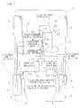
- Fig. 1 illustrates a conceptual construction of an electrically powered vehicle equipped with a control device for the electrically powered vehicle designed in accordance with the preferred embodiment of the present invention.
- the electrically powered vehicle hereinafter referred to as a vehicle 1, is a four wheeled automotive vehicle including left and right rear wheels, which are rendered to be vehicle drive wheels 2, and left and right front wheels, which are rendered to be vehicle driven and steering wheels 3.
- Each of those drive and driven wheels 2, 3 is a wheel having a corresponding tire (not shown).
- the left and right drive wheels 2 and 2 are driven by respective electric drive motors 4 and 4 that are separate and independent from each other.
- Each of those drive wheels 2 is supported by a vehicle body structure of the vehicle 1 through respective wheel support bearing assemblies 5.
- Each of the electric drive motors 4 is an in-wheel motor having a part thereof or the whole thereof incorporated within the associated drive wheel 2 and being operable to transmit a rotation to the associated drive wheel 2 through a reduction gear unit 6.
- Those electric drive motors 4, reduction gear units 6 and wheel support bearing assemblies 5 altogether form respective in-wheel motor units. It is, however, to be noted that each of the electric drive motors 4 may be of a type capable of rotationally drive the associated drive wheel 2 directly and without any reduction gear unit 6.
- Each of the electric drive motors 4 is in the form of, for example, a synchronous motor and is controlled by a drive circuit 11 including an inverter.
- the drive circuit 11 employed for each of the left and right drive wheels 2 and 2 includes a power circuit unit 11a, which utilizes a direct current of a battery (not shown) as an electric power source to output an electric drive current of each phase of the associated electric drive motor 4, and a control unit 11b for outputting of an electric voltage waveform or the like of each phase, that will becomes an alternating current of the power circuit unit 11 a, in dependence on an inputted command value, to thereby control the power circuit unit 11a.
- the command value so inputted to the control unit 11b and referred to above is represented by the torque value or the number of revolutions (i.e., the number of revolutions per unitary time).
- the vehicle 1 is provided with various sensors such as, for example, a steering angle detector 8 for detecting the angle of a steering wheel 7, an actuation amount detector 22 for detecting the amount of actuation of an accelerator pedal, rotational number detectors 9 for detecting the numbers of revolutions per unitary time of the respective drive wheels 2, and electric drive motor current detectors 10 for detecting respective electric motor currents, each of which is the drive current applied to the electric motor 4 for each of the drive wheels 2. It is, however, to be noted that in addition to the use of those detectors referred to above, the use may be additionally made of rotational number detectors (not shown) for detecting the respective numbers of revolutions of the respective driven wheels 3 and load detectors (also not shown) for detecting respective loads acting on the vehicle wheels 2 and 3.
- a steering angle detector 8 for detecting the angle of a steering wheel 7
- an actuation amount detector 22 for detecting the amount of actuation of an accelerator pedal
- rotational number detectors 9 for detecting the numbers of revolutions per unitary time of the respective drive
- the vehicle 1 is also provided with an electric control unit (ECU) 12 for controlling the vehicle in its entirety, and this electric control unit 12 is in turn provided with a drive command output section 13 for outputting a command value to each of the electric drive motors 4 for the respective drive wheels 2, a correcting section 14 and a feedback control section 15.
- the drive command output section 13 has as a basic function, a function of outputting the command value, which is dependent on the amount of actuation of the accelerator pedal to each of the drive circuits 11 for the respective drive wheels 2, and may be of a type capable of outputting the command value, which has been corrected on the basis of respective detection values of the various detectors provided in the vehicle 1.
- the drive command output section 13 may be of a type capable of performing either a torque control or a rotational number control. This drive command output section 13 outputs a torque value as the command value, if it is of the type capable of performing the torque control, but the number of revolutions if it is of the type capable of performing the rotational number control.
- the feedback control section 15 referred to above is a means for performing a feedback control to the command value which has been corrected by the correcting section 14.
- This feedback control section 15, where the torque control is performed performs a feedback control on the command value of the electric drive motor current to be outputted in dependent on the torque value obtained from an electric drive motor current value detected by the electric drive motor current detector 10.
- the feedback control section 15, where the rotational number control is performed performs a feedback control on the command value of the number of revolutions to be outputted in dependent on the number of revolutions detected by the rotational number detector 9.
- the correcting section 14 referred to above is a means for performing, among various corrections performed in the electric control unit 12, a correction in the event that the respective effective radii of the left and right drive wheels 2 and 2 differ from each other as a result of a change in tire pneumatic pressure or the like.
- the correcting section 14 performs the correction of the command value, which is to be outputted from the electric control unit 12 to each of the drive circuit 11, in accordance with a predetermined rule RL.
- This correcting section 14 is adapted to be inputted with, in addition to the command value referred to above, pieces of information necessary for the correction including a steering angle detected by the steering angle detector 8, the number of revolutions (the number of revolutions per unitary time) detected by each of the rotational number detectors 9 for the respective drive wheels 2, and electric motor currents detected by the electric drive motor current detectors 10 for the respective electric motors 4 in the drive wheels 2.
- the rule RL of the correcting section 14 referred to above is a rule used to correct the command value by using the detected steering angle as measured with respect to a traveling direction and is stipulated so that the relation between the corrected command values to be outputted to the respective drive circuits 11 for the respective left and right drive wheels 2, with respect to the detected number of revolutions of each of the drive wheels 2 and the inputted electric drive motor current will be such that rather than the relation between the command values before being corrected, the turning force induced in the vehicle 1 due to the difference in effective radius of the drive wheels 2 can be suppressed.
- the rule RL of the correcting section 14 differs depending on whether the drive command output section 13 performs the torque control or whether it performs the rotational number control. In the first place, the case applicable where the drive command output section 13 performs the torque control will be described. In this case, the rule RL has the following contents to perform either one of the following procedures (1) and (2).
- the number of revolutions Nrl of the rear left wheel and the number of revolutions Nrr of the rear right wheel, both in the equation (I) represent the respective theoretical numbers of revolutions of the left and right drive wheels 2 and 2.
- one of the drive wheels 2 and 2 which has the smaller radius than that of the other drive wheel, will transmit a relatively large driving force to the ground surface, resulting in generation of the turning force.
- drive wheel 2 having the small radius because of the relatively small effective radius, the number of revolutions of the wheel even during the straight forward travel of the vehicle tends to become larger than that exhibited by the other wheel.
- the correcting section 14 determines a reduction of the effective radius of one of the wheels as a result of, for example, a change in tire pneumatic pressure of the wheel and then corrects the drive motor torque, which is on the wheel of the higher number of revolutions, so as to reduce such drive motor torque. Accordingly, it is possible to suppress a generation of the turning force resulting from the difference between the respective effective radii of the left and right drive wheels 2 and 2 caused by, for example, the change in tire pneumatic pressure of the wheel.
- the radius of turn R of the vehicle 1 and the theoretical numbers of revolutions of each of the drive wheels 2 and 2 are calculated from the steering angle and the rotation ratios of the detected numbers of revolutions of the drive wheels to the respective theoretical numbers are determined.
- One of the drive wheels, whose determined rotational ratio exhibits a greater value than that of the other drive wheel, is regarded as accompanying a reduction in effective radius and the correction is made so as to reduce the torque on the wheel to thereby maintain a neutral steer condition. Accordingly, it is possible to suppress a generation of the turning force resulting from the difference between the respective effective radii of the left and right drive wheel 2 and 2 that is caused by, for example, the change in tire pneumatic pressure of the wheel.
- the rule RL utilized by the correcting section 14 as hereinabove described, which is applicable where the drive command output section 12 performs the rotational number control, will be described hereinafter.
- the rule RL has the following contents to perform either one of the following procedures (3) and (4).
- the drive command output section 13 controls the number of revolutions so as to be suppressed, wherefore the turning force comes to be generated.
- the torque applied to the electric drive motor 4 for the drive wheel 2 driven on the braking side is released and the commanded number of revolutions is corrected to the number of revolutions detected during the free revolution, with such drive wheel subsequently re-driven.
- the condition of free revolution is a condition, in which neither the driving force nor the braking force is generated, the number of revolutions detected during the free revolution is rendered to be the commanded number of revolutions after correction if the vehicle is traveling along a target excursion. With this number of revolutions, no turning force is generated in the vehicle. Accordingly, it is possible to suppress the generation of the turning force, which would result from the presence of a difference in effective radius between those drive wheels.
- the radius of turn R of the vehicle 1 and the theoretical numbers of revolutions of the drive wheels 2 are calculated from the steering angle and the numbers of revolutions of the drive wheels 2 are controlled so as to attain the theoretical numbers of revolutions.
- the correcting section 14 referred to above may have the rule RL of a kind having such rule contents that based on the correction control performed a number of times by the correcting section 14, the average value of the ratios between the effective radii of the drive wheels 2 can be stored, that is, the average value of those ratios between the effective radii, exhibited when calculated by means of the correction control performed a number of times, is stored and from this average value, the command value is roughly conected. If the average value discussed above is used, the control can be performed further stably.
Landscapes
- Engineering & Computer Science (AREA)
- Transportation (AREA)
- Mechanical Engineering (AREA)
- Chemical & Material Sciences (AREA)
- Combustion & Propulsion (AREA)
- Power Engineering (AREA)
- Automation & Control Theory (AREA)
- Electric Propulsion And Braking For Vehicles (AREA)
Abstract
Description
- This application is based on and claims Convention priority to
Japanese patent application No. 2009-281210, filed December 11, 2009 - The present invention relates to the control of an electrically driven vehicle such as, for example, an automotive vehicle of a kind having left and right, independent drive motors.
- The electric motorcar now attracting public attentions is considered a high performance vehicle as it makes use of left and right electric motors such as, for example, in-wheel motors that can be controlled independently from each other. In most of the electric motorcars currently available in the market, the electric motors employed are driven according to either a torque control scheme, that is, a scheme in which the electric current to be supplied to each of the electric motors is controlled, or of a scheme in which the number of revolutions of each of the electric motors is controlled. In those known control schemes, the drive wheels themselves tend to generate a turning force or a slewing force in the event that because of, for example, a change in tire pneumatic pressure, the effective radius differs between those drive wheels. The
patent document 1 listed below addresses correction of a difference in driving force brought about by the difference in tire diameters and discloses a control method utilizing threshold values to refrain from exceeding the limit. In this control method, the difference in driving forces is to a certain extent permissible. - [Patent Document 1]
JP Laid-open Patent Publication No. 2006-240402 - The correction of the difference in driving force resulting from the difference of the tire diameters, which is disclosed in the
patent document 1 listed above, is a control method in which the threshold values are utilized to avoid a possible surpass over the limits and, therefore, the difference in driving forces is permitted to a certain extent. For this reason, an improvement in vehicle traveling stability is insufficient. - In view of the foregoing, an object of the present invention is to provide a control device for an electrically powered vehicle of a type, in which even when the effective radii differ between left and right vehicle wheels because of a change in, for example, a tire pneumatic pressure in one or both of the vehicle wheels, the difference in driving forces between the left and right vehicle drive wheels can be zeroed to suppress generation of the turning force to thereby improve the vehicle traveling stability, and, also, to provide a method of so controlling in the electrically powered vehicle.
- The present invention in accordance with one aspect thereof provides a control device for an electrically powered vehicle including a plurality of drive wheels capable of respectively performing left and right drives, which are independent from each other, and electric drive motors for driving those drive wheels, that is, a control device for an electrically powered vehicle of a type employing a plurality of drive wheels, drives of those wheels being performed separately and independently from each other, and electric drive motors for driving left and right drive wheels, respectively, separately and independently from each other. In accordance with the present invention, the control device for the electrically powered vehicle referred to above includes a steering angle detector for detecting the steering angle, which is the angle of turn of a steering wheel; a rotational number detector for detecting the number of revolutions per unitary time of each of the drive wheels; an electric drive motor current detector for detecting an electric drive motor current, which is a drive current applied to an electric drive motor for each of the drive wheels; a drive command output section capable of outputting a command value in accordance with an amount of actuation of an accelerator pedal; and a correcting section for correcting the command value of an electric current value or the number of revolutions that is inputted from the drive command output section so that the corrected command value is outputted to the drive circuit for the electric drive motor for each of the drive wheels.
- The correcting section referred to above is inputted with the steering angle detected by the steering angle detector, the number of revolutions of each of the drive wheels detected by the rotational number detector and the electric drive motor current detected by the electric drive motor current detector and makes use of the steering angle as measured with respect to a traveling direction and is operable to correct the command value in accordance with a rule stipulated so that the relation between the corrected command values to be outputted to the respective drive circuits for the left and right drive wheels is such that rather than the relation between the command values before being corrected, a turning force induced in the electrically powered vehicle because of the difference in effective radius of the drive wheels can be suppressed.
- According to the above mentioned aspect of the present invention, the correcting section referred to above makes use of the steering angle as measured with respect to a traveling direction and is operable to correct the command value of the electric current or the number of revolutions in accordance with a rule stipulated so that the relation between the corrected command values to be outputted to the respective drive circuits for the left and right drive wheels is such that rather than the relation between the command values before being corrected, a turning force induced in the electrically powered vehicle because of the difference in effective radius of the drive wheels can be suppressed. Since using the steering angle as measured with respect to the traveling direction the respective electric current values applied to or the respective numbers of revolutions of the left and right drive wheels are corrected, it is possible to suppress a generation of the turning force with the difference in driving force between the left and right drive wheels set to substantially zero, thereby increasing the traveling stability.
- The rule stipulated for the correcting section depends on whether the drive command output section is capable of performing the torque control or whether the drive command output section is capable of performing the rotational number control.
- Where the drive command output section is capable of performing the torque control of the electric drive motor referred to above, the stipulated rule followed by the correcting section may have a content which is such that the command value to be outputted to the drive circuit of each of the electric drive motors for the left and right drive wheels is corrected to establish the following equation when the steering angle detected by the steering angle detector is zero:

- It is to be noted that the wording "the steering angle is zero" is to be construed as encompassing a range in which steering can be regarded as indicative of a straight forward travel.
- Where the same torque is applied to the left and right electric drive motors, one of the wheels having a relatively small effective radius than the other tends to give rise to a large driving force, which in turn leads to a generation of the turning force. In the wheel having a small effective radius, the number of wheel revolutions tends to become high even during the straight forward travel of the electrically powered vehicle as compared with a wheel having a normal size. For this reason, in the event that the difference in number of revolutions occurs between the left and right wheels when the electrically powered vehicle is driven straight forwards with no steering wheel being turned, it is determined that reduction of the effective radius of one of the wheels is caused by a change of the tire pneumatic pressure or the like. Then, the torque to be applied to the electric drive motor for the wheel with the high number of revolutions is corrected so as to be decreased. Accordingly, it is possible to suppress an undesirable generation of the turning force caused by the difference between the respective effective radii of the left and right drive wheels.
- Where the drive command output section is operable to perform the torque control of the electric drive motor referred to above, the stipulated rule followed by the correcting section may have a content which is such that when the steering angle detected by the steering angle detector indicates a turning condition, the radius of turn of the electrically powered vehicle and the respective theoretical numbers of revolutions of the left and right drive wheels and the rotation ratios of those numbers of revolutions (i.e., the left number of revolutions / the right number of revolutions) are determined from the steering angle. If the detected number of revolutions of the drive wheel is greater than the theoretical number of revolutions of the drive wheel on the same side, the command value to be outputted to the drive circuit of one of the electric drive motors, which exhibits higher rotational speed than that of the other drive wheel, is corrected by calculating the drive current of such one of the electric drive motors, so as to establish the following equation;

- When the steering wheel is turned, indicating the turning condition, the theoretical numbers of revolutions of those drive wheels and the radius of turn of the electrically powered vehicle are calculated from the steering angle. Then, the ratios between the detected numbers of revolutions of the drive wheels and the respective theoretical numbers of revolutions are determined.
- By regarding one of the drive wheels, whose determined rotational ratio exhibits a greater value than that of the other drive wheel, as accompanying a reduction in effective radius and by correcting so as to reduce the torque, a neutral steer condition is maintained. Accordingly, it is possible to suppress an undesirable generation of the turning force caused by the difference between the respective effective radii of the left and right drive wheels resulting from a change in tire pneumatic pressure.
- Where the drive command output section is operable to perform the rotational number control of the electric drive motor referred to above, the stipulated rule followed by the correcting section may have a content which is such that when the steering angle detected by the steering angle detector is zero, and in the event that one of the drive wheels is driven on a braking side, the torque applied to the electric drive motor for the drive wheel driven on the braking side is released so that the commanded number of revolutions, which is the drive command value outputted from the drive command output section, is corrected to the number of revolutions detected by the rotational number detector during a free revolution, with such one of the drive wheels subsequently re-driven.
- If the left and right electric drive motors are operated to rotate at the same number of revolutions, one of the drive wheels, which has a smaller effective radius than that of the other of the drive wheels, is likely to rotate at a high speed as led by the other of the drive wheels, which then has the larger effective radius, and, therefore, the drive command output section controls the number of revolutions so as to be suppressed, wherefore the turning force comes to be generated.
- In the event that when the steering wheel is not turned, indicating a straight forward traveling condition, the drive wheel is driven on the braking side, the torque applied to the electric drive motor for the drive wheel driven on the braking side is released so that the commanded number of revolutions is corrected to the number of revolutions detected as a result of such free revolution, with such one of the drive wheels subsequently re-driven. Accordingly, it is possible to suppress the generation of the turning force, which would result from the presence of a difference in effective radius between those drive wheels.
- Where the drive command output section is operable to perform the rotational number control of the electric drive motor referred to above, the stipulated rule followed by the correcting section may have a content which is such that when the steering angle detected by the steering angle detector indicates the turning condition, and in the event that one of the drive wheels is driven on a braking side, the torque applied to the electric drive motor for the drive wheel driven on the braking side is released to allow it to undergo a free revolution so that the number of revolutions detected by the rotational number detector during the free revolution is outputted as the corrected command value, with such one of the drive wheels subsequently re-driven.
- In the event that the steering wheel is turned, indicating the turning condition, the theoretical numbers of revolutions and the radius of turn of the electrically powered vehicle are calculated from the steering angle. Then, the drive wheels are so controlled in their numbers of revolutions so as to attain such calculated numbers of revolutions, respectively. When at this time one of the drive wheels is driven on the braking side, the torque applied to the electric drive motor for the drive wheel driven on the braking side is released so that the number of revolutions detected as a result of such free revolution is applied as the commanded number of revolutions, which will become the corrected command value, with such one of the drive wheels subsequently re-driven. Accordingly, the neutral steer condition is maintained and it is possible to suppress an undesirable generation of the turning force in the electrically powered vehicle as a result of the difference in effective radius of the drive wheel.
- In any one of the foregoing preferred embodiments of the present invention, the stipulated rule followed by the correcting section may have a content which is such that an average value of the ratios between the effective radii of the drive wheel, which were obtained from a number of correcting controls, is stored and from this average value the corrected command value is roughly corrected. The utilization of the average value as discussed above is effective to perform a further stabilized control.
- The present invention in accordance with another aspect thereof provides a method of controlling an electrically powered vehicle including a plurality of drive wheels capable of respectively performing left and right drives, which are independent from each other, and electric drive motors for driving those drive wheels. In the method, a command value is so corrected by a correcting section for correcting the command value of an electric current value or a number of revolutions inputted from a drive command output section, which is capable of outputting a command value in accordance with an amount of actuation of an accelerator pedal, the corrected command value being to be outputted to a drive circuit for the electric drive motor for each of the drive wheel, that using various detection values representative of the number of revolutions per unitary time of each of the drive wheels and the electric drive motor current, which is a drive current applied to the electric drive motor for each of the drive wheels, and also using a steering angle as measured with respect to a traveling direction, in accordance with a rule stipulated so that the relation between corrected command values to be outputted to the respective drive circuits for the left and right drive wheels is such that rather than the relation between the command values before being corrected, a turning force induced in the electrically powered vehicle because of the difference in effective radius of the drive wheels can be suppressed.
- According to the second mentioned aspect of the present invention, in a manner similar to that described in connection with the control device for the electrically powered vehicle, which is designed in accordance with the first mentioned aspect of the present invention, since using the steering angle as measured with respect to the traveling direction, the number of revolutions of the left or right wheels or the electric current value is corrected, the difference in driving force between the left and right drive wheels can be zeroed to thereby suppress the generation of the turning force and, therefore, the traveling stability can be increased advantageously.
- In one preferred embodiment of the control method referred to above, and particularly where the drive command output section is operable to perform the torque control of the electric drive motor, the stipulated rule followed by the correcting section may have a rule which is such that the command value to be outputted to the drive circuit of each of the electric drive motors for the left and right drive wheels is corrected to establish the following equation when the steering angle detected by the steering angle detector is zero:

- In the case of this method, in a manner similar to that described in connection with the control device for the electrically powered vehicle, which is designed in accordance with the first mentioned aspect of the present invention, in the event that the difference in number of revolutions between the left and right wheels is observed, reduction of the effective radius brought about by, for example, a change in tire pneumatic pressure is determined and correction is made to reduce the torque of to the electric drive motor with the high number of revolutions is corrected and, accordingly, the generation of the turning force can be advantageously suppressed.
- In one preferred embodiment of the control method referred to above, and particularly where the drive command output section is operable to perform the torque control of the electric drive motor, the stipulated rule followed by the correcting section may have a rule which is such that when the steering angle detected by the steering angle detector indicates a turning condition, the radius of turn of the electrically powered vehicle and the respective theoretical numbers of revolutions of the left and right drive wheels and the rotation ratios of those numbers of revolutions (i.e., the left number of revolutions / the right number of revolutions) are determined from the steering angle. If the detected number of revolutions of the drive wheel is greater than the theoretical number of revolutions of the drive wheel on the same side, the command value to be outputted to the drive circuit of one of the electric drive motors, which exhibits higher rotational speed than that of the other drive wheel, is corrected by calculating the drive current of such one of the electric drive motors, so as to establish the following equation;

- In such case, in a manner similar to that described in connection with the first mentioned aspect of the present invention that provides the control device of the type, in which the torque control is performed, one of the drive wheels, whose rotation ratio between the detected numbers of revolutions of the drive wheel and the theoretical number of revolutions is greater than that of the other drive wheel is regarded as having a reduction in effective radius and correction is therefore made to reduce the torque and, accordingly, the neutral steer condition can be maintained and the generation of the turning force resulting from the presence of the difference in effective radius between the left and right drive wheels can be suppressed.
- In any event, the present invention will become more clearly understood from the following description of preferred embodiments thereof, when taken in conjunction with the accompanying drawings. However, the embodiments and the drawings are given only for the purpose of illustration and explanation, and are not to be taken as limiting the scope of the present invention in any way whatsoever, which scope is to be determined by the appended claims. In the accompanying drawings, like reference numerals are used to denote like parts throughout the several views, and:
-
Fig. 1 is an explanatory diagram showing a conceptual construction illustrative of a control device for an electrically powered vehicle and a control method therefor, both designed in accordance with a preferred embodiments of the present invention; and -
Fig. 2 is an explanatory diagram showing the relationship between the number of revolutions of each of vehicle drive wheels, driving torques and radii of turn, which are exhibited during the cornering of the electrically powered vehicle. - A preferred embodiment of the present invention will now be described in detail with reference to the accompanying drawings.
Fig. 1 illustrates a conceptual construction of an electrically powered vehicle equipped with a control device for the electrically powered vehicle designed in accordance with the preferred embodiment of the present invention. The electrically powered vehicle, hereinafter referred to as avehicle 1, is a four wheeled automotive vehicle including left and right rear wheels, which are rendered to bevehicle drive wheels 2, and left and right front wheels, which are rendered to be vehicle driven andsteering wheels 3. Each of those drive and drivenwheels right drive wheels electric drive motors drive wheels 2 is supported by a vehicle body structure of thevehicle 1 through respective wheelsupport bearing assemblies 5. Each of theelectric drive motors 4 is an in-wheel motor having a part thereof or the whole thereof incorporated within the associateddrive wheel 2 and being operable to transmit a rotation to the associateddrive wheel 2 through areduction gear unit 6. Thoseelectric drive motors 4,reduction gear units 6 and wheelsupport bearing assemblies 5 altogether form respective in-wheel motor units. It is, however, to be noted that each of theelectric drive motors 4 may be of a type capable of rotationally drive the associateddrive wheel 2 directly and without anyreduction gear unit 6. - Each of the
electric drive motors 4 is in the form of, for example, a synchronous motor and is controlled by adrive circuit 11 including an inverter. Thedrive circuit 11 employed for each of the left andright drive wheels power circuit unit 11a, which utilizes a direct current of a battery (not shown) as an electric power source to output an electric drive current of each phase of the associatedelectric drive motor 4, and acontrol unit 11b for outputting of an electric voltage waveform or the like of each phase, that will becomes an alternating current of thepower circuit unit 11 a, in dependence on an inputted command value, to thereby control thepower circuit unit 11a. The command value so inputted to thecontrol unit 11b and referred to above is represented by the torque value or the number of revolutions (i.e., the number of revolutions per unitary time). - The
vehicle 1 is provided with various sensors such as, for example, asteering angle detector 8 for detecting the angle of asteering wheel 7, anactuation amount detector 22 for detecting the amount of actuation of an accelerator pedal,rotational number detectors 9 for detecting the numbers of revolutions per unitary time of therespective drive wheels 2, and electric drive motor current detectors 10 for detecting respective electric motor currents, each of which is the drive current applied to theelectric motor 4 for each of thedrive wheels 2. It is, however, to be noted that in addition to the use of those detectors referred to above, the use may be additionally made of rotational number detectors (not shown) for detecting the respective numbers of revolutions of the respective drivenwheels 3 and load detectors (also not shown) for detecting respective loads acting on thevehicle wheels - The
vehicle 1 is also provided with an electric control unit (ECU) 12 for controlling the vehicle in its entirety, and thiselectric control unit 12 is in turn provided with a drivecommand output section 13 for outputting a command value to each of theelectric drive motors 4 for therespective drive wheels 2, a correctingsection 14 and afeedback control section 15. The drivecommand output section 13 has as a basic function, a function of outputting the command value, which is dependent on the amount of actuation of the accelerator pedal to each of thedrive circuits 11 for therespective drive wheels 2, and may be of a type capable of outputting the command value, which has been corrected on the basis of respective detection values of the various detectors provided in thevehicle 1. The drivecommand output section 13 may be of a type capable of performing either a torque control or a rotational number control. This drivecommand output section 13 outputs a torque value as the command value, if it is of the type capable of performing the torque control, but the number of revolutions if it is of the type capable of performing the rotational number control. - The
feedback control section 15 referred to above is a means for performing a feedback control to the command value which has been corrected by the correctingsection 14. Thisfeedback control section 15, where the torque control is performed, performs a feedback control on the command value of the electric drive motor current to be outputted in dependent on the torque value obtained from an electric drive motor current value detected by the electric drive motor current detector 10. On the other hand, thefeedback control section 15, where the rotational number control is performed, performs a feedback control on the command value of the number of revolutions to be outputted in dependent on the number of revolutions detected by therotational number detector 9. - The correcting
section 14 referred to above is a means for performing, among various corrections performed in theelectric control unit 12, a correction in the event that the respective effective radii of the left andright drive wheels section 14 performs the correction of the command value, which is to be outputted from theelectric control unit 12 to each of thedrive circuit 11, in accordance with a predetermined rule RL. This correctingsection 14 is adapted to be inputted with, in addition to the command value referred to above, pieces of information necessary for the correction including a steering angle detected by thesteering angle detector 8, the number of revolutions (the number of revolutions per unitary time) detected by each of therotational number detectors 9 for therespective drive wheels 2, and electric motor currents detected by the electric drive motor current detectors 10 for the respectiveelectric motors 4 in thedrive wheels 2. - The rule RL of the correcting
section 14 referred to above is a rule used to correct the command value by using the detected steering angle as measured with respect to a traveling direction and is stipulated so that the relation between the corrected command values to be outputted to therespective drive circuits 11 for the respective left andright drive wheels 2, with respect to the detected number of revolutions of each of thedrive wheels 2 and the inputted electric drive motor current will be such that rather than the relation between the command values before being corrected, the turning force induced in thevehicle 1 due to the difference in effective radius of thedrive wheels 2 can be suppressed. - Specifically, the rule RL of the correcting
section 14 differs depending on whether the drivecommand output section 13 performs the torque control or whether it performs the rotational number control. In the first place, the case applicable where the drivecommand output section 13 performs the torque control will be described. In this case, the rule RL has the following contents to perform either one of the following procedures (1) and (2). - (1) When the inputted steering angle is zero:
The command value to be outputted to thedrive circuit 11 of each of theelectric drive motors 4 for the left andright drive wheels 2 is so corrected as to establish the following equation:
- (2) When the detected steering angle indicates the turning condition, the radius of turn R of the
vehicle 1 and the respective theoretical numbers of revolutions of the left andright drive wheels drive wheel 2 is greater than the theoretical number of revolutions of the drive wheel on the same side, the command value to be outputted to thedrive circuit 11 of one of theelectric drive motors 4, which exhibits higher rotational speed than that of theother drive wheel 2, is corrected by calculating the drive current of such one of theelectric drive motor 4, so as to enable the latter to assume the following equation;
- With particular reference to
Fig. 2 , the relation between the number of revolutions of each of the wheels, the drive torque applied to each of the wheels and the radius of turn of each of the wheels will now be described. Assuming that the following nomenclatures are expressed by the following symbols; - R: Radius of turn of the vehicle
- D: Tread
- H: Wheel base
- Nfl: Number of revolutions of the front left wheel
- Nfr: Number of revolutions of the front right wheel
- Nrl: Number of revolutions of the rear left wheel
- Nrr: Number of revolutions of the rear right wheel
- Tfl: Drive torque of the front left wheel
- Tfr: Drive torque of the front right wheel
- Trl: Drive torque of the rear left wheel
- Trr: Drive torque of the rear right wheel
- Rfl: Radius of turn of the front left wheel
- Rfr: Radius of turn of the front right wheel
- Rrl: Radius of turn of the rear left wheel
- Rrr: Radius of turn of the rear right wheel
- The number of revolutions Nrl of the rear left wheel and the number of revolutions Nrr of the rear right wheel, both in the equation (I) represent the respective theoretical numbers of revolutions of the left and
right drive wheels - The operation of the control device so configured as hereinabove described will now be described. In the case of the torque control type drive wheel, the operation takes place in the following manner.
- In the event that the left and
right drive wheels drive wheels such drive wheel 2 having the small radius, because of the relatively small effective radius, the number of revolutions of the wheel even during the straight forward travel of the vehicle tends to become larger than that exhibited by the other wheel. - In view of the above, when the
vehicle 1 is traveling straight forwards with thesteering wheel 7 having been not turned, but accompanying a difference in number of revolutions of the left andright drive wheels section 14 determines a reduction of the effective radius of one of the wheels as a result of, for example, a change in tire pneumatic pressure of the wheel and then corrects the drive motor torque, which is on the wheel of the higher number of revolutions, so as to reduce such drive motor torque. Accordingly, it is possible to suppress a generation of the turning force resulting from the difference between the respective effective radii of the left andright drive wheels - Also, when the
vehicle 1 is curving with thesteering wheel 7 thereof having been turned, the radius of turn R of thevehicle 1 and the theoretical numbers of revolutions of each of thedrive wheels right drive wheel - The contents of the rule RL utilized by the correcting
section 14 as hereinabove described, which is applicable where the drivecommand output section 12 performs the rotational number control, will be described hereinafter. In such case, the rule RL has the following contents to perform either one of the following procedures (3) and (4). - (3) When the detected steering angle is zero, and in the event that one of the
drive wheels 2 is driven on a braking side, the torque applied to the electric drive motor for thedrive wheel 2 driven on the braking side is released so that the commanded number of revolutions, which is the drive command value outputted from the drivecommand output section 13, is corrected to the number of revolutions detected by therotational number detector 9 during a free revolution, with such one of the drive wheels subsequently re-driven. - (4) When the steering angle detected by the steering angle detector indicates the turning condition, and in the event that one of the
drive wheels 2 is driven on a braking side, the torque applied to the electric drive motor for thedrive wheel 2 driven on the braking side is released to allow it to undergo a free revolution so that the number of revolutions detected by therotational number detector 9 during the free revolution can be applied as a commanded number of revolutions, which will become the command value after the correction, with such one of the drive wheels subsequently re-driven. - In the case of the rotational number control type drive wheel, the following operation takes place:
- If the
electric drive motors right drive wheels drive wheels 2, which has a smaller effective radius than that of the other of the drive wheels, is likely to rotate at a high speed as led by the other of thedrive wheels 2, which then has the larger effective radius, and, therefore, the drivecommand output section 13 controls the number of revolutions so as to be suppressed, wherefore the turning force comes to be generated. - In the event that the
drive wheel 2 is driven on the braking side while the vehicle is traveling straight forwards with thesteering wheel 7 not yet turned, the torque applied to theelectric drive motor 4 for thedrive wheel 2 driven on the braking side, is released and the commanded number of revolutions is corrected to the number of revolutions detected during the free revolution, with such drive wheel subsequently re-driven. Since the condition of free revolution is a condition, in which neither the driving force nor the braking force is generated, the number of revolutions detected during the free revolution is rendered to be the commanded number of revolutions after correction if the vehicle is traveling along a target excursion. With this number of revolutions, no turning force is generated in the vehicle. Accordingly, it is possible to suppress the generation of the turning force, which would result from the presence of a difference in effective radius between those drive wheels. - If the
steering wheel 7 is turned, indicating the turning condition, the radius of turn R of thevehicle 1 and the theoretical numbers of revolutions of thedrive wheels 2 are calculated from the steering angle and the numbers of revolutions of thedrive wheels 2 are controlled so as to attain the theoretical numbers of revolutions. - In the event that at that time the
drive wheel 2 is driven on the braking side, the torque applied to theelectric drive motor 4 for thatdrive wheel 2 is released and, the commanded number of revolutions is corrected to the number of revolutions detected during a free revolution, with the drive wheel subsequently re-driven, to thereby maintain a neutral steer condition. Accordingly, it is possible to suppress the generation of the turning force in the vehicle as a result of the difference in effective radius between the drive wheels. - It is to be noted that in the practice of the foregoing embodiment of the present invention, in the case where either the torque control type drive wheels or the rotational number control type drive wheels are employed, the correcting
section 14 referred to above may have the rule RL of a kind having such rule contents that based on the correction control performed a number of times by the correctingsection 14, the average value of the ratios between the effective radii of thedrive wheels 2 can be stored, that is, the average value of those ratios between the effective radii, exhibited when calculated by means of the correction control performed a number of times, is stored and from this average value, the command value is roughly conected. If the average value discussed above is used, the control can be performed further stably. - Although the present invention has been fully described in connection with the preferred embodiments thereof with reference to the accompanying drawings which are used only for the purpose of illustration, those skilled in the art will readily conceive numerous changes and modifications within the framework of obviousness upon the reading of the specification herein presented of the present invention. Accordingly, such changes and modifications are, unless they depart from the scope of the present invention as delivered from the claims annexed hereto, to be construed as included therein.
-
- 1
- Vehicle (Electrically powered vehicle)
- 2
- Drive wheel
- 3
- Driven wheel
- 4
- Electric Drive Motor
- 7
- Steering wheel
- 8
- Steering angle detector
- 9
- Rotational number detector
- 10
- Electric drive motor current detector
- 11
- Drive circuit
- 12
- Electric control unit
- 13
- Drive command output section
- 14
- Correcting section
- 21
- detector
- 22
- Accelerator pedal
- RL
- Rule


Claims (9)
- A control device for controlling an electrically powered vehicle including a plurality of drive wheels capable of respectively performing left and right drives, which are independent from each other, and electric drive motors for driving the respective drive wheels, which device comprises:a steering angle detector for detecting the steering angle, which is the angle of turn of a steering wheel;a rotational number detector for detecting the number of revolutions per unitary time of each of the drive wheels;an electric drive motor current detector for detecting an electric drive motor current, which is a drive current applied to the electric drive motor for each of the drive wheels;a drive circuit for the electric drive motor for each of the drive wheels;a drive command output section capable of outputting a command value in accordance with an amount of actuation of an accelerator pedal; anda correcting section for correcting the command value of an electric current value or the number of revolutions that is inputted from the drive command output section so that the corrected command value is outputted to the drive circuit for the electric drive motor for each of the drive wheels;wherein the steering angle detected by the steering angle detector, the number of revolutions of each of the drive wheels detected by the rotational number detector and the electric drive motor current detected by the electric drive motor current detector are inputted to the correcting section, and the correcting section makes use of the steering angle as measured with respect to a traveling direction and is operable to correct the command value in accordance with a rule stipulated so that the relation between the corrected command values to be outputted to the respective drive circuits for the left and right drive wheels is such that rather than the relation between the command values before being corrected, a turning force induced in the electrically powered vehicle because of the difference in effective radius of the drive wheels can be suppressed.
- The control device as claimed in claim 1, wherein the drive command output section is capable of performing a torque control of the electric drive motor and wherein as a content of the stipulated rule, the correcting section has such a content that the command value to be outputted to the drive circuit of each of the electric drive motors for the left and right drive wheels is corrected to establish the following equation when the steering angle detected by the steering angle detector is zero:

- The control device as claimed in claim 1, wherein the drive command output section is capable of performing a torque control of the electric drive motor and wherein as a content of the stipulated rule, the correcting section has such a content that when the steering angle detected by the steering angle detector indicates a turning condition, the radius of turn of the electrically powered vehicle and the respective theoretical numbers of revolutions of the left and right drive wheels and the rotation ratio of those numbers of revolutions are determined from the steering angle and, if the detected number of revolutions of the drive wheel is greater than the theoretical number of revolutions or the drive wheel on the same side, the command value to be outputted to the drive circuit of one of the electric drive motors, which exhibits higher rotational speed than that of the other drive wheel, is corrected by calculating the drive current of such one of the electric drive motors, so as to establish the following equation;

- The control device as claimed in claim 1, wherein the drive command output section is capable of performing a rotational number control of the electric drive motor and wherein as a content of the stipulated rule, the correcting section has such a content that when the steering angle detected by the steering angle detector is zero, and in the event that one of the drive wheels is driven on a braking side, the torque applied to the electric drive motor for the drive wheel driven on the braking side is released so that the commanded number of revolutions, which is the drive command value outputted from the drive command output section, is corrected to the number of revolutions detected by the rotational number detector during a free revolution, with such one of the drive wheels subsequently re-driven.
- The control device as claimed in claim 3, wherein the drive command output section is capable of performing a rotational number control of the electric drive motor and wherein as a content of the stipulated rule, the correcting section has such a content that when the steering angle detected by the steering angle detector indicates the turning condition, and in the event that one of the drive wheels is driven on a braking side, the torque applied to the electric drive motor for the drive wheel driven on the braking side is released to allow it to undergo a free revolution so that the number of revolutions detected by the rotational number detector during the free revolution is outputted as the corrected command value, with such one of the drive wheels subsequently re-driven.
- The control device as claimed in claim 1, wherein as a content of the stipulated rule, the correcting section has such a content that an average value of the ratios between the effective radii of the drive wheels, which were obtained from a number of correcting controls, is stored and from this average value the command value is roughly corrected.
- A method of controlling an electrically powered vehicle including a plurality of drive wheels capable of respectively performing left and right drives, which are independent from each other, and electric drive motors for driving those drive wheels, the method comprising:providing a command value of an electric current value or a number of revolutions in accordance with an amount of actuation of an accelerator pedal by a drive command output section;correcting the command value provided from the drive command output section by a correcting section, the corrected command value being to be outputted to a drive circuit of the electric drive motor for each of the drive wheels, whereinthe correcting section uses various detection values representative of the steering angle, which is the angle of turn of a steering wheel, the number of revolutions per unitary time of each of the drive wheels and the electric drive motor current, which is a drive current applied to the electric drive motor for each of the drive wheels, andthe command value is so corrected, with the steering angle being used as measured with respect to a traveling direction, in accordance with a rule stipulated so that the relation between corrected command values to be outputted to the respective drive circuits for the left and right drive wheels is such that rather than the relation between the command values before being corrected, a turning force induced in the electrically powered vehicle because of the difference in effective radius of the drive wheels can be suppressed.
- The method as claimed in claim 7, wherein the drive command output section is capable of performing a torque control of the electric drive motor and wherein the stipulated rule includes a rule in which the command value to be outputted to the drive circuit of each of the electric drive motors for the left and right drive wheels is corrected to establish the following equation when the steering angle detected by the steering angle detector is zero:

- The method as claimed in claim 7, wherein the drive command output section is capable of performing a torque control of the electric drive motor and wherein the stipulated rule includes a rule in which when the steering angle detected by the steering angle detector indicates a turning condition, the radius of turn of the electrically powered vehicle and the respective theoretical numbers of revolutions of the left and right drive wheels and the rotation ratio of those numbers of revolutions are determined from the steering angle and, if the detected number of revolutions of the drive wheel is greater than the theoretical number of revolutions, the command value to be outputted to the drive circuit of one of the electric drive motors, which exhibits higher rotational speed than that of the other drive wheel, is corrected by calculating the drive current of such one of the electric drive motors, which establishes the following equation;

Applications Claiming Priority (2)
| Application Number | Priority Date | Filing Date | Title |
|---|---|---|---|
| JP2009281210A JP5550891B2 (en) | 2009-12-11 | 2009-12-11 | Control device and control method for electric vehicle |
| PCT/JP2010/071822 WO2011071014A1 (en) | 2009-12-11 | 2010-12-06 | Control apparatus and control method for electrically driven vehicle |
Publications (2)
| Publication Number | Publication Date |
|---|---|
| EP2511124A1 true EP2511124A1 (en) | 2012-10-17 |
| EP2511124A4 EP2511124A4 (en) | 2016-04-27 |
Family
ID=44145558
Family Applications (1)
| Application Number | Title | Priority Date | Filing Date |
|---|---|---|---|
| EP10835934.0A Withdrawn EP2511124A4 (en) | 2009-12-11 | 2010-12-06 | Control apparatus and control method for electrically driven vehicle |
Country Status (5)
| Country | Link |
|---|---|
| US (1) | US9211807B2 (en) |
| EP (1) | EP2511124A4 (en) |
| JP (1) | JP5550891B2 (en) |
| CN (1) | CN102656050B (en) |
| WO (1) | WO2011071014A1 (en) |
Cited By (1)
| Publication number | Priority date | Publication date | Assignee | Title |
|---|---|---|---|---|
| CN107839546A (en) * | 2017-11-21 | 2018-03-27 | 何镜连 | Intelligent heading control loop |
Families Citing this family (13)
| Publication number | Priority date | Publication date | Assignee | Title |
|---|---|---|---|---|
| WO2013035185A1 (en) | 2011-09-08 | 2013-03-14 | 三菱電機株式会社 | Overtemperature protection device for motor |
| JP5893361B2 (en) * | 2011-11-24 | 2016-03-23 | Ntn株式会社 | Motor control device |
| WO2013081121A1 (en) * | 2011-12-01 | 2013-06-06 | Ntn株式会社 | Accelerator operation response control method for automobile equipped with electric motor |
| JP5949103B2 (en) * | 2012-04-27 | 2016-07-06 | パナソニックIpマネジメント株式会社 | Inverter unit and electric vehicle |
| WO2014054148A1 (en) * | 2012-10-04 | 2014-04-10 | トヨタ自動車株式会社 | Wheel control device, vehicle, and wheel control method |
| KR101670847B1 (en) * | 2014-04-04 | 2016-11-09 | 주식회사 와이즈오토모티브 | Apparatus and method for peripheral image generation of vehicle |
| US9709148B1 (en) * | 2016-04-20 | 2017-07-18 | Shaun Chu | Differential system with differential rate governed by variable speed motor and associated method of operation |
| KR102463694B1 (en) * | 2016-12-09 | 2022-11-07 | 현대자동차주식회사 | Method for drive controlling of vehicle using in wheel system |
| EP3679276A4 (en) | 2017-09-08 | 2021-03-24 | Chu, Shaun | DIFFERENTIAL SYSTEM INCLUDING DIFFERENTIAL SPEED PLANETARY GEARS GOVERNED BY A VARIABLE SPEED MOTOR AND ASSOCIATED PROCESS OF OPERATION |
| CN108860296B (en) * | 2018-08-24 | 2023-07-28 | 厦门理工学院 | Electric vehicle electronic differential control system and electric vehicle based on steering angle closed loop |
| JP7307000B2 (en) * | 2020-01-27 | 2023-07-11 | 株式会社ジェイテクト | steering controller |
| JP2021145413A (en) * | 2020-03-10 | 2021-09-24 | Ntn株式会社 | Drive control device for wheel independent drive type car |
| CN117124873B (en) * | 2023-08-29 | 2026-04-17 | 广州高新兴机器人有限公司 | A gyroscope-based Ackerman chassis correction method, system, and storage medium |
Family Cites Families (13)
| Publication number | Priority date | Publication date | Assignee | Title |
|---|---|---|---|---|
| JPH088722B2 (en) * | 1985-10-12 | 1996-01-29 | 株式会社安川電機 | Electric differential drive |
| JPH05176418A (en) * | 1991-03-25 | 1993-07-13 | Hitachi Ltd | Electric vehicle controller |
| JPH0662509A (en) * | 1992-08-05 | 1994-03-04 | Nissan Motor Co Ltd | Electric vehicle differential drive |
| JP3484881B2 (en) * | 1996-05-24 | 2004-01-06 | スズキ株式会社 | Motor control device for electric vehicle |
| JPH11262112A (en) * | 1998-03-13 | 1999-09-24 | Yaskawa Electric Corp | Electric trolley |
| DE10024178A1 (en) * | 2000-05-17 | 2001-12-06 | Wabco Gmbh & Co Ohg | Method for improved determination of the ratio of the radii of the wheels of a vehicle to one another |
| CN1227130C (en) * | 2002-08-14 | 2005-11-16 | 同济大学新能源汽车工程中心 | Four wheel electronic differential speed steering control system |
| JP4266164B2 (en) * | 2003-12-19 | 2009-05-20 | 株式会社日立製作所 | Tricycle control device |
| JP2006240402A (en) * | 2005-03-01 | 2006-09-14 | Nissan Motor Co Ltd | Vehicle driving force distribution control device |
| JP4301212B2 (en) * | 2005-06-03 | 2009-07-22 | 日産自動車株式会社 | Vehicle control device |
| JP4709804B2 (en) * | 2007-06-01 | 2011-06-29 | 本田技研工業株式会社 | Wheel diameter variation detector |
| JP4845839B2 (en) * | 2007-09-20 | 2011-12-28 | 株式会社日立製作所 | Electric drive vehicle |
| US8170755B2 (en) * | 2008-09-16 | 2012-05-01 | Robert Bosch Gmbh | Methods and systems for improved detection of minispare tires |
-
2009
- 2009-12-11 JP JP2009281210A patent/JP5550891B2/en not_active Expired - Fee Related
-
2010
- 2010-12-06 CN CN201080055741.XA patent/CN102656050B/en not_active Expired - Fee Related
- 2010-12-06 WO PCT/JP2010/071822 patent/WO2011071014A1/en not_active Ceased
- 2010-12-06 EP EP10835934.0A patent/EP2511124A4/en not_active Withdrawn
-
2012
- 2012-06-05 US US13/489,022 patent/US9211807B2/en not_active Expired - Fee Related
Cited By (1)
| Publication number | Priority date | Publication date | Assignee | Title |
|---|---|---|---|---|
| CN107839546A (en) * | 2017-11-21 | 2018-03-27 | 何镜连 | Intelligent heading control loop |
Also Published As
| Publication number | Publication date |
|---|---|
| CN102656050A (en) | 2012-09-05 |
| JP2011125150A (en) | 2011-06-23 |
| EP2511124A4 (en) | 2016-04-27 |
| WO2011071014A1 (en) | 2011-06-16 |
| US20120245776A1 (en) | 2012-09-27 |
| US9211807B2 (en) | 2015-12-15 |
| CN102656050B (en) | 2015-04-01 |
| JP5550891B2 (en) | 2014-07-16 |
Similar Documents
| Publication | Publication Date | Title |
|---|---|---|
| US9211807B2 (en) | Control apparatus and control method for electrically driven vehicle | |
| EP2810818B1 (en) | Electric vehicle | |
| EP2684735B1 (en) | Electric vehicle | |
| US9067507B2 (en) | Electric automobile | |
| US8843291B2 (en) | Electric vehicle | |
| EP3190000B1 (en) | Electronic stability control system for vehicle | |
| EP2679433B1 (en) | Electric automobile | |
| EP2783906B1 (en) | Electric vehicle control device | |
| EP2783896B1 (en) | Motor control device | |
| US20170015213A1 (en) | Motor drive control device | |
| EP2783895A1 (en) | Electric vehicle | |
| US10889188B2 (en) | Drive control device for vehicle with independently driven wheels | |
| JP4513612B2 (en) | Vehicle torque distribution control device | |
| WO2016125686A1 (en) | Vehicle braking/driving torque control device | |
| JP6459370B2 (en) | Drive unit and drive module | |
| WO2015002033A1 (en) | Drive torque control device | |
| WO2017018335A1 (en) | Motor drive device | |
| JP6585446B2 (en) | Vehicle braking / driving force control device | |
| JP6421533B2 (en) | Vehicle control device | |
| JP2007161190A (en) | Electric vehicle |
Legal Events
| Date | Code | Title | Description |
|---|---|---|---|
| PUAI | Public reference made under article 153(3) epc to a published international application that has entered the european phase |
Free format text: ORIGINAL CODE: 0009012 |
|
| 17P | Request for examination filed |
Effective date: 20120709 |
|
| AK | Designated contracting states |
Kind code of ref document: A1 Designated state(s): AL AT BE BG CH CY CZ DE DK EE ES FI FR GB GR HR HU IE IS IT LI LT LU LV MC MK MT NL NO PL PT RO RS SE SI SK SM TR |
|
| DAX | Request for extension of the european patent (deleted) | ||
| RA4 | Supplementary search report drawn up and despatched (corrected) |
Effective date: 20160331 |
|
| RIC1 | Information provided on ipc code assigned before grant |
Ipc: B60L 9/18 20060101AFI20160318BHEP Ipc: B60L 15/20 20060101ALI20160318BHEP |
|
| 17Q | First examination report despatched |
Effective date: 20180726 |
|
| STAA | Information on the status of an ep patent application or granted ep patent |
Free format text: STATUS: THE APPLICATION HAS BEEN WITHDRAWN |
|
| 18W | Application withdrawn |
Effective date: 20181004 |