EP2511087A2 - Method for making a workpiece - Google Patents
Method for making a workpiece Download PDFInfo
- Publication number
- EP2511087A2 EP2511087A2 EP12163724A EP12163724A EP2511087A2 EP 2511087 A2 EP2511087 A2 EP 2511087A2 EP 12163724 A EP12163724 A EP 12163724A EP 12163724 A EP12163724 A EP 12163724A EP 2511087 A2 EP2511087 A2 EP 2511087A2
- Authority
- EP
- European Patent Office
- Prior art keywords
- layer
- hard
- hard shell
- cavity
- shell
- Prior art date
- Legal status (The legal status is an assumption and is not a legal conclusion. Google has not performed a legal analysis and makes no representation as to the accuracy of the status listed.)
- Withdrawn
Links
Images


Classifications
-
- B—PERFORMING OPERATIONS; TRANSPORTING
- B29—WORKING OF PLASTICS; WORKING OF SUBSTANCES IN A PLASTIC STATE IN GENERAL
- B29C—SHAPING OR JOINING OF PLASTICS; SHAPING OF MATERIAL IN A PLASTIC STATE, NOT OTHERWISE PROVIDED FOR; AFTER-TREATMENT OF THE SHAPED PRODUCTS, e.g. REPAIRING
- B29C44/00—Shaping by internal pressure generated in the material, e.g. swelling or foaming ; Producing porous or cellular expanded plastics articles
- B29C44/02—Shaping by internal pressure generated in the material, e.g. swelling or foaming ; Producing porous or cellular expanded plastics articles for articles of definite length, i.e. discrete articles
- B29C44/08—Shaping by internal pressure generated in the material, e.g. swelling or foaming ; Producing porous or cellular expanded plastics articles for articles of definite length, i.e. discrete articles using several expanding or moulding steps
- B29C44/083—Increasing the size of the cavity after a first part has foamed, e.g. substituting one mould part with another
- B29C44/086—Increasing the size of the cavity after a first part has foamed, e.g. substituting one mould part with another and feeding more material into the enlarged cavity
-
- B—PERFORMING OPERATIONS; TRANSPORTING
- B29—WORKING OF PLASTICS; WORKING OF SUBSTANCES IN A PLASTIC STATE IN GENERAL
- B29C—SHAPING OR JOINING OF PLASTICS; SHAPING OF MATERIAL IN A PLASTIC STATE, NOT OTHERWISE PROVIDED FOR; AFTER-TREATMENT OF THE SHAPED PRODUCTS, e.g. REPAIRING
- B29C44/00—Shaping by internal pressure generated in the material, e.g. swelling or foaming ; Producing porous or cellular expanded plastics articles
- B29C44/02—Shaping by internal pressure generated in the material, e.g. swelling or foaming ; Producing porous or cellular expanded plastics articles for articles of definite length, i.e. discrete articles
- B29C44/04—Shaping by internal pressure generated in the material, e.g. swelling or foaming ; Producing porous or cellular expanded plastics articles for articles of definite length, i.e. discrete articles consisting of at least two parts of chemically or physically different materials, e.g. having different densities
-
- B—PERFORMING OPERATIONS; TRANSPORTING
- B29—WORKING OF PLASTICS; WORKING OF SUBSTANCES IN A PLASTIC STATE IN GENERAL
- B29C—SHAPING OR JOINING OF PLASTICS; SHAPING OF MATERIAL IN A PLASTIC STATE, NOT OTHERWISE PROVIDED FOR; AFTER-TREATMENT OF THE SHAPED PRODUCTS, e.g. REPAIRING
- B29C44/00—Shaping by internal pressure generated in the material, e.g. swelling or foaming ; Producing porous or cellular expanded plastics articles
- B29C44/34—Auxiliary operations
- B29C44/3461—Making or treating expandable particles
-
- B—PERFORMING OPERATIONS; TRANSPORTING
- B29—WORKING OF PLASTICS; WORKING OF SUBSTANCES IN A PLASTIC STATE IN GENERAL
- B29K—INDEXING SCHEME ASSOCIATED WITH SUBCLASSES B29B, B29C OR B29D, RELATING TO MOULDING MATERIALS OR TO MATERIALS FOR MOULDS, REINFORCEMENTS, FILLERS OR PREFORMED PARTS, e.g. INSERTS
- B29K2995/00—Properties of moulding materials, reinforcements, fillers, preformed parts or moulds
- B29K2995/0037—Other properties
- B29K2995/007—Hardness
-
- B—PERFORMING OPERATIONS; TRANSPORTING
- B29—WORKING OF PLASTICS; WORKING OF SUBSTANCES IN A PLASTIC STATE IN GENERAL
- B29L—INDEXING SCHEME ASSOCIATED WITH SUBCLASS B29C, RELATING TO PARTICULAR ARTICLES
- B29L2031/00—Other particular articles
- B29L2031/48—Wearing apparel
- B29L2031/4807—Headwear
- B29L2031/4814—Hats
- B29L2031/4821—Helmets
Definitions
- the invention relates to a method for producing a workpiece having at least one hard layer or hard shell as well as a comparatively soft cushion layer materially bonded thereto.
- the problem to be solved is essentially to ensure a good and reproducible quality of hard shell and cushion layer in a molding of the type specified in addition to a permanently strong connection between the hard shell and cushion layer.
- This object is achieved in that first the hard shell or layer is formed in a first cavity, and that then the cushion layer is formed in a second cavity, which between the previously formed and now used as a die hard shell or layer and a male is made.
- the invention is based on the general idea of using the previously formed hard shell or layer as the boundary wall of the cavity provided for the formation of the cushion layer. Even if the foam material should initially have a high and for the material of the hard shell or layer optionally even destructive temperature, this remains harmless with respect to the production quality of the molded part to be produced, because the density of the foam material in comparison to the density of the material Hard shell or layer is comparatively low and accordingly the heat input from the foam material into the material of the hard shell or layer remains extremely low.
- thermoplastic polymer material for the production of the hard shell or layer readily a thermoplastic polymer material can be used and an intimate and resilient connection between the hard shell or layer and cushion layer is generated during foaming of the intended for forming the cushion layer cavity.
- the method according to the invention differs above all in the fact that a different sequence of the process steps is provided. In this way, it is reliably prevented that in the production of the hard shell or layer a previously generated foam part could collapse or be destroyed.
- the hard shell or layer can be injection-molded in a basically known manner, wherein the die used during the injection molding process or die of the mold with the therein or first remaining hard shell or layer as a die or male for the formation of the foam material to be created cavity can be used.
- molded parts with a foam or cushion layer between two hard shells or layers can be produced without further ado.
- the two hard shells or layers can be produced, for example by an injection molding process. Thereafter, these two shells or layers are preferably together with the matrices and patrices of the previous injection molding process which they continue to carry as dies And Patrizen the now used for the formation of the foam cavity to be created, which is then foamed in a conventional manner.
- a first cavity 4 is produced between a die 1 and a male part 2 of a molding tool 3, which corresponds to the desired shape of a hard shell or layer to be produced.
- this hard shell or layer 5 is then produced in a conventional manner by injection molding, by injecting into the cavity 4 a thermoplastic polymer material.
- the male part 2 is detached from the shell or layer 5 and adjusted so that between the male part 2 and the further the shell or layer 5 bearing die 1, a second cavity 6 produced becomes.
- this cavity 6 is then foamed with particle foam according to FIG. C, which thereby bonds to the shell or layer 5 in a materially bonded manner.
- a molded part is produced with a hard shell or layer 5 and a cushion layer 7 connected to it in a materially bonded manner.
- the female part 1 and the male part 2 can be made separable into segments. Instead, it is also possible to press in porosity in the die 1 or male part 2 a gaseous or vaporous separating fluid.
- the in Fig. 2 differs from the manufacturing process of Fig. 1 essentially only in that, for producing the second cavity 6 serving for forming the foam, a die 20 is used whose shape deviates from the die 2 provided for the injection molding process for producing the hard shell or layer 5.
- the invention has for its object to show the structural features of a system that produces inline sandwich components with a core of particle foam.
- a combination of technology consisting of a inserts injection molding machine for the production of injection molded component bodies with subsequent inline connection of the body part to a hollow body component, and a molding machine for particle foam production for inline production of the core of the hollow body made of particle foam.
- the combination technology system is structurally designed such that in at least one of the two tool installation spaces 1 and 2 of the insert machine, the hollow body is produced, and is foamed in the remaining tool installation space of the hollow body after a rotational movement of the insert with particle foam.
- the foaming apparatus is structurally designed such that it foams the hollow body within the cavity in the tool installation space.
- the insert 5 is designed structurally as a turntable with a vertical axis to the machine axis of the insert machine.
- hollow bodies are manufactured in both tool installation spaces 1 and 2 and the particle foam apparatus is structurally designed such that the hollow bodies are produced at the positions 3 and 4 of the insert with particle foam for the finished component.
- the invention comprises a combination technology, comprising a insert injection molding machine for producing component bodies with an injection-molded outer layer and a molding machine for inline production of the inner layer of particle foam and subsequent connection of the partial body to an overall component.
- the combination technology system is structurally designed such that the part of the injection molded body in the mold installation space of the insert machine. After opening the closing unit, the central mold clamping area, which is movable about a vertical axis, is rotated by 90 °.
- the construction is now designed such that on at least one of the cavities, which are rotated transversely to the longitudinal axis of the insert machine, an open molding device for production of particle foam is moved, and the tool halves are closed.
- the molding device is structurally designed such that particle foam is introduced into the hollow body, air is sucked out of the chamber and the particles are foamed by means of added steam overpressure. Thereafter, the particle foam molding device is released from the mold halves. Moving members provided for certain tool areas are pulled, and the center mold mounting area is again rotated 90 °. Thereafter, surface action elements move between the open mold halves to activate the injection molded part bodies to be joined. After pulling the activation elements the mold clamping area of the insert machine is closed and the component joined. Then the demoulding takes place.
- the insert machine is constructively designed so that textile reinforcements can be inserted before the injection process.
- All devices can be structurally designed such that in a first sequence of the injection-molded part body is made in the tool with at least one cavity. After opening the tool, the part-body (s) is removed with a handling and converted into the molding machine for particle foam production.
- the structural design of the molding machine and the associated tools are such that the component is present by inline production of the second particle foam body part as prefabricated component after demolding.
Abstract
Description
Die Erfindung bezieht sich auf ein Verfahren zur Herstellung eines Werkstückes mit zumindest einer Hartschicht bzw. Hartschale sowie einer damit stoffschlüssig verbundenen, vergleichsweise weichen Polsterschicht.The invention relates to a method for producing a workpiece having at least one hard layer or hard shell as well as a comparatively soft cushion layer materially bonded thereto.
Für viele Einsatzzwecke sind Artikel notwendig, die einerseits eine formstabile Schale und andererseits eine damit verbundene Polsterschicht besitzen. Beispielhaft kann auf Schutzhelme für Rad- und Motorradfahrer oder auf gepolsterte Sitzschalen verwiesen werden.For many purposes articles are necessary, on the one hand have a dimensionally stable shell and on the other hand, a related cushioning layer. By way of example, reference can be made to protective helmets for cyclists and motorcyclists or to upholstered seat shells.
Grundsätzlich besteht die Möglichkeit, die Hartschale und das zugehörige Polsterteil getrennt herzustellen und nachfolgend mit herkömmlichen Fügeverfahren zu verbinden. Der damit verbundene Aufwand ist jedoch unerfreulich hoch. Außerdem ist die Festigkeit der Verbindung oftmals ungenügend.In principle, it is possible to manufacture the hard shell and the associated cushion part separately and subsequently to connect them with conventional joining methods. However, the effort involved is unpleasantly high. In addition, the strength of the connection is often insufficient.
Grundsätzlich sind auch Kleb- oder Schweißverbindungen zwischen der Polsterschicht und der Hartschale möglich. Hier kann zwar eine hinreichend belastbare und dauerhafte Verbindung erzielt werden, jedoch ist der Herstellungsaufwand unerwünscht hoch.In principle, adhesive or welded joints between the cushioning layer and the hard shell are also possible. Although a sufficiently durable and durable connection can be achieved here, the production outlay is undesirably high.
Aus der
Bei diesem Herstellungsprozess ist also vorgesehen, innerhalb einer Formanordnung an ein zuvor geformtes Schaumstoffteil eine Deckschicht anzuformen.In this manufacturing process, it is therefore intended to form a cover layer within a mold arrangement on a previously molded foam part.
Versuche haben gezeigt, dass dieses Verfahren weitestgehend unpraktikabel ist. Denn die Qualität der Polsterschicht des fertigen Formteiles ist regelmäßig ungenügend.Experiments have shown that this method is largely impractical. Because the quality of the cushion layer of the finished molded part is regularly insufficient.
Hier setzt die Erfindung an. Die zu lösende Aufgabe besteht im Wesentlichen darin, bei einem Formteil der eingangs angegebenen Art neben einer dauerhaft festen Verbindung zwischen Hartschale und Polsterschicht eine gute und reproduzierbare Qualität von Hartschale und Polsterschicht zu gewährleisten.This is where the invention starts. The problem to be solved is essentially to ensure a good and reproducible quality of hard shell and cushion layer in a molding of the type specified in addition to a permanently strong connection between the hard shell and cushion layer.
Diese Aufgabe wird erfindungsgemäß dadurch gelöst, dass zunächst die Hartschale bzw. -schicht in einer ersten Kavität geformt wird, und dass danach die Polsterschicht in einer zweiten Kavität geformt wird, welche zwischen der zuvor geformten und nunmehr als Matrize benutzten Hartschale bzw. -schicht und einer Patrize hergestellt wird.This object is achieved in that first the hard shell or layer is formed in a first cavity, and that then the cushion layer is formed in a second cavity, which between the previously formed and now used as a die hard shell or layer and a male is made.
Die Erfindung beruht auf dem allgemeinen Gedanken, als Begrenzungswand der für die Ausformung der Polsterschicht vorgesehenen Kavität die zuvor ausgeformte Hartschale bzw. -schicht einzusetzen. Auch wenn das Schaummaterial bei seiner Ausformung zunächst eine hohe und für das Material der Hartschale bzw. -schicht gegebenenfalls sogar zerstörerische Temperatur aufweisen sollte, bleibt dies bezüglich der Produktionsqualität des zu erzeugenden Formteiles unbedenklich, weil die Dichte des Schaummaterials im Vergleich zur Dichte des Materials der Hartschale bzw. -schicht vergleichsweise gering ist und dementsprechend der Wärmeeintrag vom Schaummaterial in das Material der Hartschale bzw. -schicht äußerst gering bleibt.The invention is based on the general idea of using the previously formed hard shell or layer as the boundary wall of the cavity provided for the formation of the cushion layer. Even if the foam material should initially have a high and for the material of the hard shell or layer optionally even destructive temperature, this remains harmless with respect to the production quality of the molded part to be produced, because the density of the foam material in comparison to the density of the material Hard shell or layer is comparatively low and accordingly the heat input from the foam material into the material of the hard shell or layer remains extremely low.
Dies bietet den Vorteil, dass für die Herstellung der Hartschale bzw. -schicht ohne Weiteres ein thermoplastisches Polymermaterial eingesetzt werden kann und beim Ausschäumen der zur Formung der Polsterschicht vorgesehenen Kavität eine innige und belastbare Verbindung zwischen Hartschale bzw. -schicht und Polsterschicht erzeugt wird.This has the advantage that for the production of the hard shell or layer readily a thermoplastic polymer material can be used and an intimate and resilient connection between the hard shell or layer and cushion layer is generated during foaming of the intended for forming the cushion layer cavity.
Von dem aus der
Gemäß einer bevorzugten Ausführungsform der Erfindung kann die Hartschale bzw. -schicht in grundsätzlich bekannter Weise spritzgegossen werden, wobei die beim Spritzgussprozess eingesetzte Matrize oder Patrize der Gussform mit der darin bzw. daran zunächst verbleibenden Hartschale bzw. -schicht als Matrize bzw. Patrize der für die Ausformung des Schaummaterials zu erstellenden Kavität eingesetzt werden kann.According to a preferred embodiment of the invention, the hard shell or layer can be injection-molded in a basically known manner, wherein the die used during the injection molding process or die of the mold with the therein or first remaining hard shell or layer as a die or male for the formation of the foam material to be created cavity can be used.
Mit der Erfindung lassen sich auch ohne Weiteres Formteile mit einer Schaumstoff- bzw. Polsterschicht zwischen zwei Hartschalen bzw. -schichten erzeugen. Hier können zunächst die beiden Hartschalen bzw. -schichten hergestellt werden, beispielsweise durch einen Spritzgussprozess. Danach werden diese beiden Schalen bzw. Schichten vorzugsweise zusammen mit den sie weiterhin tragenden Matrizen und Patrizen des vorangegangenen Spritzgussprozesses als Matrizen und Patrizen der nunmehr für die Ausformung des Schaumstoffes zu erstellenden Kavität eingesetzt, die dann in herkömmlicher Weise ausgeschäumt wird.With the invention, molded parts with a foam or cushion layer between two hard shells or layers can be produced without further ado. Here, first, the two hard shells or layers can be produced, for example by an injection molding process. Thereafter, these two shells or layers are preferably together with the matrices and patrices of the previous injection molding process which they continue to carry as dies And Patrizen the now used for the formation of the foam cavity to be created, which is then foamed in a conventional manner.
Im Übrigen wird hinsichtlich bevorzugter Merkmale der Erfindung auf die Ansprüche und die nachfolgende Erläuterung der Zeichnung verwiesen, anhand der das erfindungsgemäße Verfahren näher beschrieben wird.Incidentally, with regard to preferred features of the invention to the claims and the following explanation of the drawing, reference is made to the method of the invention will be described in more detail.
Schutz wird nicht nur für angegebene oder dargestellte Merkmalskombinationen, sondern auch für prinzipiell beliebige Kombinationen der angegebenen oder dargestellten Einzelmerkmale beansprucht.Protection is claimed not only for specified or illustrated feature combinations, but also for any combination of the specified or illustrated individual features.
In der Zeichnung zeigt
- Fig. 1
- eine schematisierte Darstellung der Herstellung eines Formteiles mit einer Hartschicht sowie einer damit stoffschlüssig verbundenen Polsterschicht,
- Fig. 2
- einen gegenüber
Fig. 1 abgewandelten Herstellungsprozess, bei dem ein Formteil mit besonders ausgeformter Polsterschicht hergestellt wird.
- Fig. 1
- a schematic representation of the production of a molded part with a hard layer and a cohesively connected thereto padding layer,
- Fig. 2
- one opposite
Fig. 1 modified manufacturing process in which a molding is made with specially shaped cushion layer.
Gemäß dem Bild A der
Nach hinreichender Aushärtung bzw. Verfestigung der Schale bzw. Schicht 5 wird die Patrize 2 von der Schale bzw. Schicht 5 abgelöst und derart eingestellt, dass zwischen der Patrize 2 und der weiterhin die Schale bzw. Schicht 5 tragenden Matrize 1 eine zweite Kavität 6 hergestellt wird. In einem nachfolgenden Prozessschritt wird dann diese Kavität 6 gemäß dem Bild C mit Partikelschaum ausgeschäumt, der sich dabei stoffschlüssig mit der Schale bzw. Schicht 5 verbindet. Im Ergebnis wird auf diese Weise ein Formteil mit einer Hartschale bzw. -schicht 5 und einer damit stoffschlüssig verbundenen Polsterschicht 7 hergestellt.After sufficient hardening or solidification of the shell or
Um das Formteil 5, 7 bzw. die Hartschale bzw. -schicht 5 leichter aus dem Formwerkzeug heraustrennen bzw. von der Patrize 2 abtrennen zu können, können die Matrize 1 und die Patrize 2 in Segmente zerlegbar ausgebildet sein. Statt dessen ist es auch möglich, über Porösitäten in der Matrize 1 bzw. Patrize 2 ein gas- oder dampfförmiges Trennfluid einzupressen.In order to be able to more easily remove the
Der in
Nachfolgend werden noch zusätzliche Erläuterungen zu Vorrichtungen für die Durchführung des oben dargestellten Herstellungsverfahrens gegeben:
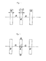
- Aus dem Gebrauchsmuster Az. 202011004211.1 ist eine Wendeplattenmaschine bekannt, mit der Sprizgiess-Bauteile mittels maschinenintegrierter Fügetechnik zu einem Vollkörper mit Hohlraum verbunden werden. Dabei zeigt
Fig. 3 schematisch die Schliessseite der Wendeplattenmaschine als Seitenansicht. Dabei ergibt sich der Werkzeugeinbauraum 1 durch diefeste Formaufspannplatte 6 und die verschieb- unddrehbare Mittelplatte 5 sowie derWerkzeugeinbauraum 2 durch die bewegliche Formaufspannplatte 7 und die verschieb- unddrehbare Mittelplatte 5. Als weitere Erläuterung zeigtFig. 4 eine schematische Draufsicht auf die Schliessseite der Wendeplattenmaschine, mit den aus Sicht der Werkzeugeinbauräumefreien Positionen 3 und 4 der Wendeplatte.
- From the utility model Az. 202011004211.1 a turning plate machine is known, are connected to the Sprizgiess components by means of machine-integrated joining technology to a solid body with cavity. It shows
Fig. 3 schematically the closing side of the insert machine as a side view. This results in the tool installation space 1 through thefixed platen 6 and the displaceable androtatable center plate 5 and thetool installation space 2 by the movable platen 7 and the displaceable androtatable center plate 5. As further explanation showsFig. 4 a schematic plan view of the closing side of the insert machine, with the view of the tool installation spacesfree positions
Des Weiteren ist die Herstellung von Artikeln aus Partikelschaum auf dafür vorgesehenen Formteilautomaten bekannt, die mittels Dampfüberdruck zum fertigen Teil ausgeschäumt werden. Das Konstruktionsprinzip der Wendeplattenmaschine ermöglicht es, zusammen mit dem Formteilautomaten zur Partikelschaumherstellung, eine neue Anlage konstruktiv auszulegen, zur Herstellung von Sandwichbauteilen mit spritzgegossener Aussenschale und einem Kern aus Partikelschaum.Furthermore, the production of articles made of particle foam on designated molding machines is known, which are foamed by steam overpressure to the finished part. The design principle of the insert machine, together with the molding machine for particle foam production, makes it possible to design a new system constructively for the production of sandwich components with an injection-molded outer shell and a core made of particle foam.
Der Erfindung liegt die Aufgabe zugrunde, die konstruktiven Merkmale einer Anlage aufzuzeigen, die inline Sandwich Bauteile mit einem Kern aus Partikelschaum produziert. Hierfür eignet sich eine Kombinationstechnologie, bestehend aus einer Wendeplatten-Spritzgiessmaschine zur Herstellung von spritzgegossenen Bauteilkörpern mit anschliessender Inline-Verbindung der Teilkörper zu einem Hohlkörperbauteil, sowie einem Formteil-Automaten zur Partikelschaumherstellung zur Inline-Fertigung des Kerns des Hohlkörpers aus Partikelschaum. Dabei ist die Kombinationstechnologie-Anlage konstruktiv derart ausgelegt, dass in mindestens einem der zwei Werkzeugeinbauräume 1 und 2 der Wendeplattenmaschine der Hohlkörper hergestellt wird, und in dem verbleibenden Werkzeugeinbauraum der Hohlkörper nach einer Drehbewegung der Wendeplatte mit Partikelschaum ausgeschäumt wird. Die Ausschäumapparatur ist dabei konstruktiv derart ausgelegt, dass sie den Hohlkörper innerhalb der Kavität im Werkzeugeinbauraum ausschäumt.The invention has for its object to show the structural features of a system that produces inline sandwich components with a core of particle foam. For this purpose, a combination of technology, consisting of a inserts injection molding machine for the production of injection molded component bodies with subsequent inline connection of the body part to a hollow body component, and a molding machine for particle foam production for inline production of the core of the hollow body made of particle foam. In this case, the combination technology system is structurally designed such that in at least one of the two
Insbesondere kann vorgesehen sein, dass die Wendeplatte 5 auch konstruktiv als Drehtisch mit vertikaler Achse zur Maschinenachse der Wendeplattenmaschine ausgestaltet ist.In particular, it can be provided that the
Außerdem ist zweckmäßig, wenn Hohlkörper in beiden Werkzeugeinbauräumen 1 und 2 gefertigt werden und die Partikelschaum-Apparatur konstruktiv derart ausgelegt ist, dass die Hohlkörper an den Positionen 3 und 4 der Wendeplatte mit Partikelschaum zum fertigen Bauteil produziert werden.In addition, it is expedient if hollow bodies are manufactured in both
Im Übrigen umfasst die Erfindung eine Kombinationstechnologie, bestehend aus einer Wendeplatten-Spritzgiessmaschine zur Herstellung von Bauteilkörpern mit spritzgegossener Aussenschicht sowie einem Formteilautomaten zur Inline-Herstellung der Innenschicht aus Partikelschaum sowie anschliessender Verbindung der Teilkörper zu einem Gesamtbauteil. Dabei ist die Kombinationstechnologie-Anlage konstruktiv derart ausgelegt, dass die Teilspritzkörper im Werkzeugeinbauraum der Wendeplattenmaschine geformt werden. Nach dem Öffnen der Schliesseinheit wird der um eine vertikale Achse bewegliche mittlere Formaufspannbereich um 90[deg.] gedreht. Die Konstruktion ist nun so ausgelegt, dass auf mindestens eine der quer zur Längsachse der Wendeplattenmaschine gedrehten Kavitäten, eine offene Formteileinrichtung zur Partikelschaumherstellung bewegt wird, und die Werkzeughälften verschliesst. Die Formteileinrichtung ist konstruktiv derart ausgebildet, dass Partikelschaum in den Hohlkörper eingegeben wird, Luft aus der Kammer abgesaugt wird und die Partikel mittels zugegebenen Dampfüberdrucks ausgeschäumt werden. Danach wird die Partikelschaum-Formteileinrichtung von den Werkzeughälften gelöst. Für bestimmte Werkzeugbereiche vorgesehene bewegliche Elements werden gezogen, und der mittlere Formaufspannbereich wird erneut um 90[deg.] gedreht. Danach fahren Oberflächenaktionselemente zwischen die offenen Werkzeughälften zur Aktivierung der zu verbindenden Spritzgiessteilkörper. Nach dem Ziehen der Aktivierungselemente wird der Formaufspannbereich der Wendeplattenmaschine geschlossen und das Bauteil gefügt. Danach erfolgt die Entformung.Incidentally, the invention comprises a combination technology, comprising a insert injection molding machine for producing component bodies with an injection-molded outer layer and a molding machine for inline production of the inner layer of particle foam and subsequent connection of the partial body to an overall component. In this case, the combination technology system is structurally designed such that the part of the injection molded body in the mold installation space of the insert machine. After opening the closing unit, the central mold clamping area, which is movable about a vertical axis, is rotated by 90 °. The construction is now designed such that on at least one of the cavities, which are rotated transversely to the longitudinal axis of the insert machine, an open molding device for production of particle foam is moved, and the tool halves are closed. The molding device is structurally designed such that particle foam is introduced into the hollow body, air is sucked out of the chamber and the particles are foamed by means of added steam overpressure. Thereafter, the particle foam molding device is released from the mold halves. Moving members provided for certain tool areas are pulled, and the center mold mounting area is again rotated 90 °. Thereafter, surface action elements move between the open mold halves to activate the injection molded part bodies to be joined. After pulling the activation elements the mold clamping area of the insert machine is closed and the component joined. Then the demoulding takes place.
Zweckmäßig ist die Wendeplattenmaschine konstruktiv derart ausgelegt, dass vor dem Spritzvorgang Textilverstärkungen eingelegt werden können.Suitably, the insert machine is constructively designed so that textile reinforcements can be inserted before the injection process.
Alle Vorrichtungen können konstruktiv derart ausgelegt sein, dass in einer ersten Sequenz der spritzgegossene Teilkörper im Werkzeug mit mindestens einer Kavität gefertigt wird. Nach dem Öffnen des Werkzeugs wird der/die Teilkörper mit einem Handling entnommen und in den Formteilautomaten zur Partikelschaumherstellung umgesetzt. Die konstruktive Ausgestaltung des Formteilautomaten sowie die dazugehörigen Werkzeuge sind derart, dass das Bauteil durch inline Herstellung des zweiten Partikelschaum-Teilkörpers als Fertigbauteil nach der Entformung vorliegt.All devices can be structurally designed such that in a first sequence of the injection-molded part body is made in the tool with at least one cavity. After opening the tool, the part-body (s) is removed with a handling and converted into the molding machine for particle foam production. The structural design of the molding machine and the associated tools are such that the component is present by inline production of the second particle foam body part as prefabricated component after demolding.
Claims (8)
dadurch gekennzeichnet,
dass die Hartschale bzw. -schicht (5) in einer ersten Kavität (4) geformt wird, und dass danach die Polsterschicht (7) in einer zweiten Kavität (6) geformt wird, welche zwischen der zuvor geformten und nunmehr als Matrize benutzten Hartschale bzw. -schicht (5) und einer Patrize (2,20) hergestellt wird.Process for the production of molded parts, such as protective helmets and the like, with at least one hard layer or hard shell and a comparatively soft cushion layer materially bonded thereto,
characterized,
in that the hard shell or layer (5) is formed in a first cavity (4), and in that the cushioning layer (7) is formed in a second cavity (6) which is located between the previously formed and now used as a die hard shell or . Layer (5) and a male part (2,20) is produced.
dadurch gekennzeichnet,
dass die Hartschale bzw. -schicht (5) bei Ausformung der Polsterschicht (7) an einer für die Ausformung der Hartschale bzw. -schicht (5) verwendeten Matrize (1) verbleibt.Method according to claim 1,
characterized,
that the hard shell or layer (5) used in forming the cushion layer (7) to one for the formation of the hard shell or layer (5) die (1) remains.
dadurch gekennzeichnet,
dass die Hartschale bzw. -schicht (5) mittels eines Spritzgussprozesses erzeugt wird.Method according to claim 1 or 2,
characterized,
that the hard shell or layer (5) is produced by an injection molding process.
dadurch gekennzeichnet,
dass die Hartschale bzw. -schicht (5) aus einem thermoplastischen Polymermaterial spritzgegossen wird.Method according to claim 3,
characterized,
in that the hard shell or layer (5) is injection-molded from a thermoplastic polymer material.
dadurch gekennzeichnet,
dass zur Erzeugung der Polsterschicht (7) in die zweite Kavität (6) Partikelschaumstoff eingeschäumt wird.Method according to one of claims 1 to 4,
characterized,
that particle foam is foamed into the second cavity (6) to produce the cushion layer (7).
dadurch gekennzeichnet,
dass der Partikelschaumstoff mit einer Temperatur nahe dem Schmelzpunkt des Materials der Hartschale bzw. -schicht (5) eingeschäumt wird.Method according to one of claims 1 to 5,
characterized,
that the particle foam is foamed at a temperature close to the melting point of the material of the hard shell or layer (5).
dadurch gekennzeichnet,
dass ein Formteil mit einer zwischen zwei Hartschalen bzw. -schichten (5) angeordneten Polsterschicht hergestellt wird, indem die beiden zuvor hergestellten Schalen bzw. Schichten (5) als Matrize und Patrize an einer nachfolgend mit Polstermaterial ausgeschäumten Kavität eingesetzt werden.Method according to one of claims 1 to 6,
characterized,
that a molded part is produced with an disposed between two hard shells or layers (5) the cushion layer by the two shells or layers previously prepared (5) are used as matrix and patrix on a subsequently foamed with cushioning material cavity.
dadurch gekennzeichnet,
dass die Hartschalen bzw. -schichten (5) von den jeweils für ihre Ausformung verwendeten Matrizen bzw. Patrizen getragen werden.Method according to claim 7,
characterized,
in that the hard shells or layers (5) are carried by the respective dies or male parts used for their shaping.
Applications Claiming Priority (4)
| Application Number | Priority Date | Filing Date | Title |
|---|---|---|---|
| DE202011005245U DE202011005245U1 (en) | 2011-04-13 | 2011-04-13 | Transfer plant for the production of components made of particle foam and injection-molded shell |
| DE202011005247U DE202011005247U1 (en) | 2011-04-13 | 2011-04-13 | Plant for the production of sandwich components with injection-molded outer shell and a core of particle foam |
| DE201110078668 DE102011078668A1 (en) | 2011-07-05 | 2011-07-05 | Method for manufacturing helmet utilized by e.g. bicyclist, involves forming cushion layer in cavity and providing cushion layer between hard-shell or layer and male mold part, where hard-shell or layer is utilized as female mold part |
| DE201120106011 DE202011106011U1 (en) | 2011-09-22 | 2011-09-22 | Plant for the production of sandwich components from half shells with injection-molded outside and a core made of particle foam |
Publications (2)
| Publication Number | Publication Date |
|---|---|
| EP2511087A2 true EP2511087A2 (en) | 2012-10-17 |
| EP2511087A3 EP2511087A3 (en) | 2015-07-29 |
Family
ID=46027626
Family Applications (1)
| Application Number | Title | Priority Date | Filing Date |
|---|---|---|---|
| EP12163724.3A Withdrawn EP2511087A3 (en) | 2011-04-13 | 2012-04-11 | Method for making a workpiece |
Country Status (1)
| Country | Link |
|---|---|
| EP (1) | EP2511087A3 (en) |
Cited By (2)
| Publication number | Priority date | Publication date | Assignee | Title |
|---|---|---|---|---|
| WO2015086118A1 (en) * | 2013-12-09 | 2015-06-18 | Audi Ag | Method for manufacturing a vehicle body element and vehicle body element |
| DE102014015710A1 (en) | 2014-10-23 | 2016-04-28 | Vereinigung zur Förderung des Instituts für Kunststoffverarbeitung in Industrie und Handwerk an der Rhein.-Westf. Technischen Hochschule Aachen e.V. | Process for welding plastic particles to foam-like products |
Citations (1)
| Publication number | Priority date | Publication date | Assignee | Title |
|---|---|---|---|---|
| EP1299219B1 (en) | 2000-07-12 | 2004-10-06 | Fraunhofer-Gesellschaft zur Förderung der angewandten Forschung e.V. | Method for producing moulded parts made of particle foam and comprising a covering layer |
Family Cites Families (7)
| Publication number | Priority date | Publication date | Assignee | Title |
|---|---|---|---|---|
| US2908943A (en) * | 1957-10-25 | 1959-10-20 | Bill Jack Scient Instr Co | Process for molding two-layer polyurethane articles |
| US3935044A (en) * | 1971-12-23 | 1976-01-27 | Noel Daly | Method of manufacturing improved protective headgear |
| CH676446A5 (en) * | 1983-04-19 | 1991-01-31 | Kork Ag Boswil | Moulded plate made of plastics material |
| US5702810A (en) * | 1992-03-10 | 1997-12-30 | Mitsubishi Chemical Corporation | Cushioning composite molded article and a process for production thereof |
| DE4304751C2 (en) * | 1993-02-17 | 1998-08-20 | Bayerische Motoren Werke Ag | Process for the production of a plastic part |
| FR2764229B1 (en) * | 1997-06-06 | 1999-08-20 | Cera | PROCESS FOR THE PRODUCTION OF A SOUNDPROOFING PANEL |
| DE102006033059A1 (en) * | 2006-07-14 | 2008-01-17 | Huperz Automotive Systems Gmbh & Co.Kg | Headrest for a motor vehicle, comprises an injection moulded carrier from a hard component and a covering layer from a soft component having a structured surface arranged on the Headrest |
-
2012
- 2012-04-11 EP EP12163724.3A patent/EP2511087A3/en not_active Withdrawn
Patent Citations (1)
| Publication number | Priority date | Publication date | Assignee | Title |
|---|---|---|---|---|
| EP1299219B1 (en) | 2000-07-12 | 2004-10-06 | Fraunhofer-Gesellschaft zur Förderung der angewandten Forschung e.V. | Method for producing moulded parts made of particle foam and comprising a covering layer |
Cited By (3)
| Publication number | Priority date | Publication date | Assignee | Title |
|---|---|---|---|---|
| WO2015086118A1 (en) * | 2013-12-09 | 2015-06-18 | Audi Ag | Method for manufacturing a vehicle body element and vehicle body element |
| US10828810B2 (en) | 2013-12-09 | 2020-11-10 | Audi Ag | Method for the production of a vehicle body element and vehicle body element |
| DE102014015710A1 (en) | 2014-10-23 | 2016-04-28 | Vereinigung zur Förderung des Instituts für Kunststoffverarbeitung in Industrie und Handwerk an der Rhein.-Westf. Technischen Hochschule Aachen e.V. | Process for welding plastic particles to foam-like products |
Also Published As
| Publication number | Publication date |
|---|---|
| EP2511087A3 (en) | 2015-07-29 |
Similar Documents
| Publication | Publication Date | Title |
|---|---|---|
| EP0210587B1 (en) | Method of manufacturing an upholstery element and apparatus for carrying out this method | |
| DE102009060689B4 (en) | Process for producing a fiber-reinforced component and device for carrying out the process | |
| DE102010056293B4 (en) | Method for producing a hollow fiber composite component and molded body | |
| EP3231572B1 (en) | Tool and method for manufacturing a foam article, and foam article | |
| DE102011105775B4 (en) | Method for injection molding of plastic molded parts made of thermoplastic material | |
| DE102010063094A1 (en) | Method for producing a material-hybrid component | |
| DE102020106725B4 (en) | Method and tool for producing a particle foam molded part | |
| WO2009052889A1 (en) | Process and device for producing a moulding with a predetermined rupture line for an airbag opening | |
| EP1282500B1 (en) | Method and device for making a cast part from a plastic/metal compound and device use | |
| DE102006004906B4 (en) | mold | |
| DE2157132A1 (en) | Injection moulding hollow articles prodn - with components welded following moulding | |
| EP2540471A2 (en) | Method for manufacturing moulds and mould | |
| DE102012010469A1 (en) | Method for manufacturing fiber reinforced component, involves arranging pre-mold semi-finished material with moderate temperature shell elements in tool to be provided with plastic material, where fiber reinforced component is cured | |
| EP2511087A2 (en) | Method for making a workpiece | |
| DE10110908B4 (en) | Method for producing a multilayer composite part and tool | |
| DE10039332A1 (en) | Molding process for a decorative inlay containing plastic component, comprises locating a connecting area of two materials in a joint gap in a mold half, inserting a nose and injecting melt around connecting area | |
| DE102010018114B4 (en) | Process for the production of components by means of polymer or plastic casting or fiber composite plastics | |
| DE102011078668A1 (en) | Method for manufacturing helmet utilized by e.g. bicyclist, involves forming cushion layer in cavity and providing cushion layer between hard-shell or layer and male mold part, where hard-shell or layer is utilized as female mold part | |
| EP2681027A2 (en) | Method and device for producing a component | |
| DE1965368B2 (en) | Method of making laminates by successively injecting at least two batches of plastic material into a mold cavity | |
| DE102012019803A1 (en) | Method for manufacturing particle foam-mold part e.g. sun visor of motor car, involves forming regions of mold part with certain thickness, cooling, curing and maintaining mold part, opening foam shaping tool, and ejecting mold part | |
| DE102018203726A1 (en) | Method for producing a sandwich component | |
| DE102020115696B4 (en) | Process for producing a molded part | |
| EP2732951B1 (en) | Method for manufacturing a cladding part and cladding part produced by means of such a method | |
| DE102010006407A1 (en) | Method for manufacturing plastic construction part, involves injecting plastic component into cavity of injection molding tool and injecting another plastic component into cavity |
Legal Events
| Date | Code | Title | Description |
|---|---|---|---|
| PUAI | Public reference made under article 153(3) epc to a published international application that has entered the european phase |
Free format text: ORIGINAL CODE: 0009012 |
|
| AK | Designated contracting states |
Kind code of ref document: A2 Designated state(s): AL AT BE BG CH CY CZ DE DK EE ES FI FR GB GR HR HU IE IS IT LI LT LU LV MC MK MT NL NO PL PT RO RS SE SI SK SM TR |
|
| AX | Request for extension of the european patent |
Extension state: BA ME |
|
| PUAL | Search report despatched |
Free format text: ORIGINAL CODE: 0009013 |
|
| AK | Designated contracting states |
Kind code of ref document: A3 Designated state(s): AL AT BE BG CH CY CZ DE DK EE ES FI FR GB GR HR HU IE IS IT LI LT LU LV MC MK MT NL NO PL PT RO RS SE SI SK SM TR |
|
| AX | Request for extension of the european patent |
Extension state: BA ME |
|
| RIC1 | Information provided on ipc code assigned before grant |
Ipc: B29C 44/08 20060101AFI20150624BHEP Ipc: B29C 44/34 20060101ALI20150624BHEP Ipc: B29C 44/04 20060101ALI20150624BHEP Ipc: B29L 31/48 20060101ALN20150624BHEP |
|
| 17P | Request for examination filed |
Effective date: 20151111 |
|
| RBV | Designated contracting states (corrected) |
Designated state(s): AL AT BE BG CH CY CZ DE DK EE ES FI FR GB GR HR HU IE IS IT LI LT LU LV MC MK MT NL NO PL PT RO RS SE SI SK SM TR |
|
| GRAP | Despatch of communication of intention to grant a patent |
Free format text: ORIGINAL CODE: EPIDOSNIGR1 |
|
| STAA | Information on the status of an ep patent application or granted ep patent |
Free format text: STATUS: GRANT OF PATENT IS INTENDED |
|
| INTG | Intention to grant announced |
Effective date: 20200805 |
|
| STAA | Information on the status of an ep patent application or granted ep patent |
Free format text: STATUS: THE APPLICATION IS DEEMED TO BE WITHDRAWN |
|
| 18D | Application deemed to be withdrawn |
Effective date: 20201103 |