EP2511037B1 - A method of weld cladding with simultaneous deposition of weld on a side and cryogenic cooling on the opposite side ; Apparatus for performing such method - Google Patents
A method of weld cladding with simultaneous deposition of weld on a side and cryogenic cooling on the opposite side ; Apparatus for performing such method Download PDFInfo
- Publication number
- EP2511037B1 EP2511037B1 EP12250091.1A EP12250091A EP2511037B1 EP 2511037 B1 EP2511037 B1 EP 2511037B1 EP 12250091 A EP12250091 A EP 12250091A EP 2511037 B1 EP2511037 B1 EP 2511037B1
- Authority
- EP
- European Patent Office
- Prior art keywords
- weld
- coolant
- substrate
- alloy
- welding torch
- Prior art date
- Legal status (The legal status is an assumption and is not a legal conclusion. Google has not performed a legal analysis and makes no representation as to the accuracy of the status listed.)
- Not-in-force
Links
Images



Classifications
-
- B—PERFORMING OPERATIONS; TRANSPORTING
- B23—MACHINE TOOLS; METAL-WORKING NOT OTHERWISE PROVIDED FOR
- B23K—SOLDERING OR UNSOLDERING; WELDING; CLADDING OR PLATING BY SOLDERING OR WELDING; CUTTING BY APPLYING HEAT LOCALLY, e.g. FLAME CUTTING; WORKING BY LASER BEAM
- B23K9/00—Arc welding or cutting
- B23K9/04—Welding for other purposes than joining, e.g. built-up welding
- B23K9/044—Built-up welding on three-dimensional surfaces
- B23K9/046—Built-up welding on three-dimensional surfaces on surfaces of revolution
- B23K9/048—Built-up welding on three-dimensional surfaces on surfaces of revolution on cylindrical surfaces
-
- B—PERFORMING OPERATIONS; TRANSPORTING
- B23—MACHINE TOOLS; METAL-WORKING NOT OTHERWISE PROVIDED FOR
- B23K—SOLDERING OR UNSOLDERING; WELDING; CLADDING OR PLATING BY SOLDERING OR WELDING; CUTTING BY APPLYING HEAT LOCALLY, e.g. FLAME CUTTING; WORKING BY LASER BEAM
- B23K10/00—Welding or cutting by means of a plasma
- B23K10/02—Plasma welding
- B23K10/027—Welding for purposes other than joining, e.g. build-up welding
-
- B—PERFORMING OPERATIONS; TRANSPORTING
- B23—MACHINE TOOLS; METAL-WORKING NOT OTHERWISE PROVIDED FOR
- B23K—SOLDERING OR UNSOLDERING; WELDING; CLADDING OR PLATING BY SOLDERING OR WELDING; CUTTING BY APPLYING HEAT LOCALLY, e.g. FLAME CUTTING; WORKING BY LASER BEAM
- B23K26/00—Working by laser beam, e.g. welding, cutting or boring
- B23K26/14—Working by laser beam, e.g. welding, cutting or boring using a fluid stream, e.g. a jet of gas, in conjunction with the laser beam; Nozzles therefor
- B23K26/1462—Nozzles; Features related to nozzles
-
- B—PERFORMING OPERATIONS; TRANSPORTING
- B23—MACHINE TOOLS; METAL-WORKING NOT OTHERWISE PROVIDED FOR
- B23K—SOLDERING OR UNSOLDERING; WELDING; CLADDING OR PLATING BY SOLDERING OR WELDING; CUTTING BY APPLYING HEAT LOCALLY, e.g. FLAME CUTTING; WORKING BY LASER BEAM
- B23K26/00—Working by laser beam, e.g. welding, cutting or boring
- B23K26/20—Bonding
- B23K26/32—Bonding taking account of the properties of the material involved
-
- B—PERFORMING OPERATIONS; TRANSPORTING
- B23—MACHINE TOOLS; METAL-WORKING NOT OTHERWISE PROVIDED FOR
- B23K—SOLDERING OR UNSOLDERING; WELDING; CLADDING OR PLATING BY SOLDERING OR WELDING; CUTTING BY APPLYING HEAT LOCALLY, e.g. FLAME CUTTING; WORKING BY LASER BEAM
- B23K26/00—Working by laser beam, e.g. welding, cutting or boring
- B23K26/34—Laser welding for purposes other than joining
- B23K26/342—Build-up welding
-
- B—PERFORMING OPERATIONS; TRANSPORTING
- B23—MACHINE TOOLS; METAL-WORKING NOT OTHERWISE PROVIDED FOR
- B23K—SOLDERING OR UNSOLDERING; WELDING; CLADDING OR PLATING BY SOLDERING OR WELDING; CUTTING BY APPLYING HEAT LOCALLY, e.g. FLAME CUTTING; WORKING BY LASER BEAM
- B23K26/00—Working by laser beam, e.g. welding, cutting or boring
- B23K26/70—Auxiliary operations or equipment
- B23K26/702—Auxiliary equipment
-
- B—PERFORMING OPERATIONS; TRANSPORTING
- B23—MACHINE TOOLS; METAL-WORKING NOT OTHERWISE PROVIDED FOR
- B23K—SOLDERING OR UNSOLDERING; WELDING; CLADDING OR PLATING BY SOLDERING OR WELDING; CUTTING BY APPLYING HEAT LOCALLY, e.g. FLAME CUTTING; WORKING BY LASER BEAM
- B23K35/00—Rods, electrodes, materials, or media, for use in soldering, welding, or cutting
- B23K35/22—Rods, electrodes, materials, or media, for use in soldering, welding, or cutting characterised by the composition or nature of the material
- B23K35/24—Selection of soldering or welding materials proper
- B23K35/30—Selection of soldering or welding materials proper with the principal constituent melting at less than 1550°C
- B23K35/3033—Ni as the principal constituent
-
- B—PERFORMING OPERATIONS; TRANSPORTING
- B23—MACHINE TOOLS; METAL-WORKING NOT OTHERWISE PROVIDED FOR
- B23K—SOLDERING OR UNSOLDERING; WELDING; CLADDING OR PLATING BY SOLDERING OR WELDING; CUTTING BY APPLYING HEAT LOCALLY, e.g. FLAME CUTTING; WORKING BY LASER BEAM
- B23K35/00—Rods, electrodes, materials, or media, for use in soldering, welding, or cutting
- B23K35/22—Rods, electrodes, materials, or media, for use in soldering, welding, or cutting characterised by the composition or nature of the material
- B23K35/24—Selection of soldering or welding materials proper
- B23K35/30—Selection of soldering or welding materials proper with the principal constituent melting at less than 1550°C
- B23K35/3053—Fe as the principal constituent
- B23K35/308—Fe as the principal constituent with Cr as next major constituent
-
- B—PERFORMING OPERATIONS; TRANSPORTING
- B23—MACHINE TOOLS; METAL-WORKING NOT OTHERWISE PROVIDED FOR
- B23K—SOLDERING OR UNSOLDERING; WELDING; CLADDING OR PLATING BY SOLDERING OR WELDING; CUTTING BY APPLYING HEAT LOCALLY, e.g. FLAME CUTTING; WORKING BY LASER BEAM
- B23K9/00—Arc welding or cutting
- B23K9/16—Arc welding or cutting making use of shielding gas
-
- B—PERFORMING OPERATIONS; TRANSPORTING
- B23—MACHINE TOOLS; METAL-WORKING NOT OTHERWISE PROVIDED FOR
- B23K—SOLDERING OR UNSOLDERING; WELDING; CLADDING OR PLATING BY SOLDERING OR WELDING; CUTTING BY APPLYING HEAT LOCALLY, e.g. FLAME CUTTING; WORKING BY LASER BEAM
- B23K9/00—Arc welding or cutting
- B23K9/18—Submerged-arc welding
-
- B—PERFORMING OPERATIONS; TRANSPORTING
- B23—MACHINE TOOLS; METAL-WORKING NOT OTHERWISE PROVIDED FOR
- B23K—SOLDERING OR UNSOLDERING; WELDING; CLADDING OR PLATING BY SOLDERING OR WELDING; CUTTING BY APPLYING HEAT LOCALLY, e.g. FLAME CUTTING; WORKING BY LASER BEAM
- B23K9/00—Arc welding or cutting
- B23K9/32—Accessories
-
- B—PERFORMING OPERATIONS; TRANSPORTING
- B23—MACHINE TOOLS; METAL-WORKING NOT OTHERWISE PROVIDED FOR
- B23K—SOLDERING OR UNSOLDERING; WELDING; CLADDING OR PLATING BY SOLDERING OR WELDING; CUTTING BY APPLYING HEAT LOCALLY, e.g. FLAME CUTTING; WORKING BY LASER BEAM
- B23K2101/00—Articles made by soldering, welding or cutting
- B23K2101/04—Tubular or hollow articles
- B23K2101/06—Tubes
-
- B—PERFORMING OPERATIONS; TRANSPORTING
- B23—MACHINE TOOLS; METAL-WORKING NOT OTHERWISE PROVIDED FOR
- B23K—SOLDERING OR UNSOLDERING; WELDING; CLADDING OR PLATING BY SOLDERING OR WELDING; CUTTING BY APPLYING HEAT LOCALLY, e.g. FLAME CUTTING; WORKING BY LASER BEAM
- B23K2103/00—Materials to be soldered, welded or cut
- B23K2103/02—Iron or ferrous alloys
- B23K2103/04—Steel or steel alloys
- B23K2103/05—Stainless steel
-
- B—PERFORMING OPERATIONS; TRANSPORTING
- B23—MACHINE TOOLS; METAL-WORKING NOT OTHERWISE PROVIDED FOR
- B23K—SOLDERING OR UNSOLDERING; WELDING; CLADDING OR PLATING BY SOLDERING OR WELDING; CUTTING BY APPLYING HEAT LOCALLY, e.g. FLAME CUTTING; WORKING BY LASER BEAM
- B23K2103/00—Materials to be soldered, welded or cut
- B23K2103/08—Non-ferrous metals or alloys
-
- B—PERFORMING OPERATIONS; TRANSPORTING
- B23—MACHINE TOOLS; METAL-WORKING NOT OTHERWISE PROVIDED FOR
- B23K—SOLDERING OR UNSOLDERING; WELDING; CLADDING OR PLATING BY SOLDERING OR WELDING; CUTTING BY APPLYING HEAT LOCALLY, e.g. FLAME CUTTING; WORKING BY LASER BEAM
- B23K2103/00—Materials to be soldered, welded or cut
- B23K2103/18—Dissimilar materials
-
- B—PERFORMING OPERATIONS; TRANSPORTING
- B23—MACHINE TOOLS; METAL-WORKING NOT OTHERWISE PROVIDED FOR
- B23K—SOLDERING OR UNSOLDERING; WELDING; CLADDING OR PLATING BY SOLDERING OR WELDING; CUTTING BY APPLYING HEAT LOCALLY, e.g. FLAME CUTTING; WORKING BY LASER BEAM
- B23K2103/00—Materials to be soldered, welded or cut
- B23K2103/18—Dissimilar materials
- B23K2103/26—Alloys of Nickel and Cobalt and Chromium
-
- B—PERFORMING OPERATIONS; TRANSPORTING
- B23—MACHINE TOOLS; METAL-WORKING NOT OTHERWISE PROVIDED FOR
- B23K—SOLDERING OR UNSOLDERING; WELDING; CLADDING OR PLATING BY SOLDERING OR WELDING; CUTTING BY APPLYING HEAT LOCALLY, e.g. FLAME CUTTING; WORKING BY LASER BEAM
- B23K2103/00—Materials to be soldered, welded or cut
- B23K2103/50—Inorganic materials other than metals or composite materials
Definitions
- the present invention relates to a method of weld cladding according to the preamble of claim 1 (see, as a pure example, US5 362 937 A ), for increasing the corrosion resistance of weld cladding.
- Weld cladding (which may alternatively be referred to as weld overlay) comprises providing a corrosion or oxidation resistant surface on a less resistant material by weld deposition. Weld cladding using corrosion resistant alloys is used to increase the corrosion resistance of normal alloys in for example highly corrosive environments such as sea water, nuclear and cooling water applications.
- weld overlays/cladding using for example stainless steel and high Nickel alloys can result in the final weld having a high iron (Fe) content.
- a high iron content significantly reduces the pitting corrosion resistance of the weld cladding. Industry typically allows a maximum level of 36% dilution of iron in the weld cladding. The corrosion resistance of a weld having an amount of iron in excess of this maximum level is known to have significantly reduced resistance to pitting corrosion.
- US 4 505 945 discloses a method of plasma spraying a member in which the surface of the member being treated with the plasma coating is cooled by means of a cryogenic spray applied to the surface before the plasma spray is applied.
- US 5 362 937 discloses a method of weld cladding a metal plate in which the reverse side to that being treated is cooled by means of a water spray to minimise deformation.
- US 4 152 568 discloses a method of forming a pipe from metal plate in which the metal plate is formed into a tube and its edges butt welded by a first weld. The opposite side to the first weld is then welded whilst the original weld is cooled by means of a water or cryogenic spray.
- a method of weld cladding comprising: providing a welding torch adjacent a first surface of a substrate; providing a coolant head adjacent a second, reverse, surface of the substrate, wherein the coolant head comprises at least one nozzle for ejecting coolant to impinge on the second surface of the substrate; and simultaneously depositing a weld on the first surface while applying a coolant to the second surface of the substrate, the weld being of a material able to be diluted by the substrate, wherein that the coolant is cryogenic carbon dioxide, see claim 1.
- the substrate may be a pipe.
- Crystalogenic coolant is herein defined as a coolant having a temperature of less than -50 °C.
- Embodiments of the invention can minimise the mixing of the new weld metal with the metal of the substrate.
- the weld cladding has been found to have significantly less dilution. "Dilution” is herein defined as the amount of mixing of the melting base metal with the new weld metal. As a result the corrosion resistance of the weld cladding is significantly improved.
- Embodiments of the invention provide a method of managing the heat input into the material substrate and the weld metal. Embodiments of the invention therefore help to limit the potential damage the high heat input can cause. By providing coolant to the reverse side of the substrate embodiments of the invention do not disrupt the welding process of the cladding.
- embodiments of the invention can extend the life of the component in harsh service environments. This can lead to increased productivity of a plant, lower manufacturing costs and lower deformation levels.
- harsh service environments include nuclear pipe cladding, nuclear reactor vessel nozzles, boiler tube overlays, high corrosion zone pipe cladding applications in off shore oil and gas industries and valve bodies in off shore oil and gas industries.
- the coolant head is substantially axially aligned with the welding torch, for example the coolant head and welding torch may be substantially coaxial.
- the coolant head may be arranged to track the movement of the welding torch. It will be appreciated that the movement of the welding torch and coolant head is relative movement with respect to the substrate.
- the substrate may move and the coolant head and welding torch may be fixed or the substrate may be fixed and the welding torch and coolant head may track across the surface.
- the coolant head comprises, according to the present invention, at least one cooling nozzle for ejecting cryogenic coolant towards a surface of the substrate.
- the cryogenic coolant may thus impinge upon the surface of the substrate.
- the nozzle may be positioned approximately 10 to 50mm from the surface of the pipe.
- the cryogenic coolant is, according to the present invention, carbon dioxide, for example liquid or solid carbon dioxide.
- the cryogenic coolant passes, according to the present invention, through a nozzle causing the liquid coolant to expand.
- the cryogenic coolant may pass through a coolant head having a plurality of nozzles.
- the expansion of the coolant may advantageously result in a change of state of the coolant from liquid to solid.
- expansion through the nozzle transforms liquid carbon dioxide to solid snow carbon dioxide.
- Solid snow carbon dioxide advantageously has been found to provide the highest heat transfer characteristics due to the heat of sublimation as the snow contacts the substrate and transforms from the solid phase directly to the gas phase.
- cryogenic coolant impinges upon the surface at or ahead of the point of deposition of the weld.
- cryogenic coolant impinges upon the surface between 0 and 10mm ahead of the point of deposition of the weld, for example the nozzle may be between 0 and 20 mm ahead of the welding torch.
- the weld cladding has a weld deposition region proximal to the welding torch where a weld cladding is being deposited and a weld solidification region downstream of the welding torch where a deposited weld is cooling and/or solidifying.
- the coolant head is arranged to apply a cryogenic coolant to the opposing side of the substrate in both the weld deposition region and the weld solidification region.
- the coolant head comprises at least one cooling nozzle for ejecting cryogenic coolant to impinge upon the surface of the substrate in the weld deposition region and at least one further cooling nozzle, downstream of the welding torch, for ejecting cryogenic coolant to impinge upon the surface of the substrate in the weld solidification region.
- the coolant may be applied around the full internal circumferential surface of a substrate/ pipe.
- the coolant head may have a distributed array of nozzles shaped to substantially match the internal shape of the substrate.
- the nozzle may at least one radial nozzle
- the nozzle is preferably a 360° radial cooling nozzle, for example a spray ring.
- the spray ring may be positioned within the pipe to effect the cooling.
- the cooling nozzle may for example comprise a circumferentially distributed array of nozzles, for example the cooling nozzle may comprise at least 12 nozzles.
- the flow rate at which the cryogenic coolant is provided is dictated by the rate at which it is desired to cool the weld in order to reduce the dilution.
- the flow rate of the cryogenic coolant can be between 1 and 5 kg/min.
- the weld cladding may comprise stainless steel or high Nickel alloys.
- the high Nickel alloys are selected from alloy 625, alloy 825, alloy 725, alloy C276, alloy C22, alloy monel, alloy 905L, alloy 316L and alloy 304L.
- a weld substrate 2 (which may for example be a pipe) has a top surface 4 and a bottom surface 6.
- a welding torch 8 is positioned above the top surface 4 of the weld substrate 2.
- the welding torch 8 may for example be arranged for any one of Submerged Arc Welding(SAW), a Manual Metal Arc (MMA) welding, Gas Metal Arc Welding (GMAW), Flux Cored Arc Welding (FCAW), Gas Tungsten Arc welding (GTAW), Plasma Arc Welding (PAW) and laser welding.
- SAW Submerged Arc Welding
- MMA Manual Metal Arc
- GMAW Gas Metal Arc Welding
- FCAW Flux Cored Arc Welding
- GTAW Gas Tungsten Arc welding
- PAW Plasma Arc Welding
- a coolant head 1 is provided at the reverse side of the substrate.
- the coolant head 1 comprises a first cooling nozzle 10 and a second cooling nozzle 12 each positioned below and directed towards the bottom surface 6 of the weld substrate 2.
- the coolant head 1 is generally axially aligned with the welding torch 6.
- the first cooling nozzle 10 is positioned slightly ahead of the weld deposition head, for example the nozzle may be approximately 10mm ahead of the welding torch 8.
- the second cooling nozzle 12 is downstream of the first nozzle 10 and of the welding torch 8.
- the region of the weld substrate 2 which is impinged upon by the coolant may be arranged to be between 10 mm in front of and coaxial with the welding torch 8.
- the first and second cooling nozzles 10, 12 comprise inlets 20, 22 for delivering coolant, which in the preferred embodiment is provided as liquid carbon dioxide, under pressure to the bottom surface 6 of the weld substrate 2.
- the inlets 20,22 may be connected to a single supply of coolant (for example the inlets may be in series or parallel fluid communication).
- the coolant is delivered under pressure, typically in the range of 15 to 45 bar.
- the nozzles 10, 12 provide outlets 30, 32 arranged to eject coolant towards the bottom surface 6 of the weld substrate 2.
- the stand-off distance of the nozzles 10" 12 from the bottom surface 6 of the weld substrate 2 is typically in the order of 10 mm to 50 mm.
- the nozzle outlet 30, 32 typically have a relatively small internal radius, for example the nozzle outlet 30 may have an outlet diameter of less than 2mm.
- the nozzle outlet may have a outlet diameter of between 0.5mm and 2mm, for example 1.2 mm.
- the welding torch 8 deposits the weld cladding 40 on the top surface 4 of the weld substrate 2 at a deposition point in a weld deposition region 52.
- the welding torch 8 is moved relative to the substrate 2 (from right to left as shown by the arrow A in Figure 2 ). As the welding torch 8 moves along the substrate the deposited weld cladding 40 solidifies and cools in a weld solidification region 54.
- a coolant head 1 is positioned below the substrate 2 on the reverse side with respect to the welding torch 8.
- the coolant head 1 tracks the movement of the welding torch 8 so as to maintain the alignment of the nozzles 10, 12 with respect to the relative position of the welding torch 8 and substrate 2.
- liquid carbon dioxide is pumped into the coolant head 1 through inlets 20, 22.
- the liquid carbon dioxide is pumped out of the nozzles 10, 12 under high pressure.
- the first cooling nozzle 10 cools the part of the weld substrate 2 which is directly ahead (or upstream) of the welding torch 8 in order to affect maximum cooling efficiency in order to minimise weld dilution.
- the second cooling nozzle 12 generally cools the part of the weld substrate 2 which is directly behind (i.e. downstream of) the welding torch 8, where the weld is solidifying. It will be noted that the coolant impinges upon the substrate 2 and spreads along the longitudinal surface of the substrate 2 such that cryogenic coolant is spread across the bottom surface 6 from a point B ahead of the welding torch 8 to a point B' which is behind the welding torch 8. Thus coolant is distributed by the coolant head 1 to the substrate 2 ahead of the weld region 52, in the weld region 52 and in the solidification region 54.
- the liquid carbon dioxide turns into solid carbon dioxide snow 50, having a temperature of approximately -70 °C as it expands under pressure through the outlets 30, 32 of the nozzles 10, 12.
- the carbon dioxide snow 50 sublimes immediately on contact with the bottom surface 6 of the weld substrate 2.
- the flow rate of the carbon dioxide is dictated by the rate at which it is desired to cool the weld in order to reduce dilution.
- the mass flow rate of coolant may, for example, be up to 20 kg/min.
- the mass flow rate may be between 1 and 5 kg/min.
- the rapid cooling of the bottom surface 6 of the weld substrate 2 helps to manage the heat input into the substrate 2. This helps to limit the potential damage of the high heat input, and advantageously minimises weld dilution.
- FIGS 3 and 4 show a cooling nozzle 10' which is particularly suitable for use in a coolant head 1 according to embodiments of the invention in which the substrate 2 is a pipe.
- the nozzle 10' suitable for use in an embodiment of the invention can comprise a body portion 62 having twelve radially extending nozzle outlets 30'. The nozzles outlets 30' are evenly distributed about the circumference of the body 62.
- the cooling nozzle 10' comprises an inlet 64 which has a threaded connector 66 for receiving a pipe to provide a source of cryogenic coolant (not shown).
- the inlet 64 of the cooling nozzle 10' is connected to a pipe 68 supplying liquid carbon dioxide.
- the liquid carbon dioxide is pumped out of the twelve radially extending nozzles outlets 30' under high pressure. Due to the even distribution of the nozzles outets 30' around the entire circumference of the body 62 the cooling nozzle 10' ensures that coolant is delivered simultaneously and evenly to the entire internal circumferential surface of the weld 3. As the liquid carbon dioxide expands under pressure through the nozzle outlets 30' it transforms into solid carbon dioxide snow 70.
- FIGS. 5A and 5B show the cooling effect of carbon dioxide cryogenic coolant in Kilowatts for differing jet sizes ( Figure 5A ) and at different flow rates ( Figure 5B ).
- the relationship between cooling power and jet size was found to be non linear while the relationship between the cooling power and flow rate was linear.
- Figure 5C shows the relationship between the flow rate of coolant through different sized jet nozzles at a constant pressure. It will be noted that the relationship between the flow rate and nozzle size was found to be nonlinear.
- carbon dioxide has been found to have the highest heat transfer characteristics due to the immediate sublimation of the carbon dioxide snow upon contact with the hot weld surface.
- other coolants may vaporise without contacting the weld surface.
Landscapes
- Engineering & Computer Science (AREA)
- Physics & Mathematics (AREA)
- Mechanical Engineering (AREA)
- Plasma & Fusion (AREA)
- Optics & Photonics (AREA)
- Arc Welding In General (AREA)
Description
- The present invention relates to a method of weld cladding according to the preamble of claim 1 (see, as a pure example,
US5 362 937 A ), for increasing the corrosion resistance of weld cladding. - Weld cladding (which may alternatively be referred to as weld overlay) comprises providing a corrosion or oxidation resistant surface on a less resistant material by weld deposition. Weld cladding using corrosion resistant alloys is used to increase the corrosion resistance of normal alloys in for example highly corrosive environments such as sea water, nuclear and cooling water applications.
- It has however been found that weld overlays/cladding using for example stainless steel and high Nickel alloys can result in the final weld having a high iron (Fe) content. A high iron content significantly reduces the pitting corrosion resistance of the weld cladding. Industry typically allows a maximum level of 36% dilution of iron in the weld cladding. The corrosion resistance of a weld having an amount of iron in excess of this maximum level is known to have significantly reduced resistance to pitting corrosion.
-
US 4 505 945 discloses a method of plasma spraying a member in which the surface of the member being treated with the plasma coating is cooled by means of a cryogenic spray applied to the surface before the plasma spray is applied. -
US 5 362 937 discloses a method of weld cladding a metal plate in which the reverse side to that being treated is cooled by means of a water spray to minimise deformation. -
US 4 152 568 discloses a method of forming a pipe from metal plate in which the metal plate is formed into a tube and its edges butt welded by a first weld. The opposite side to the first weld is then welded whilst the original weld is cooled by means of a water or cryogenic spray. - According to the invention there is provided a method of weld cladding comprising: providing a welding torch adjacent a first surface of a substrate; providing a coolant head adjacent a second, reverse, surface of the substrate, wherein the coolant head comprises at least one nozzle for ejecting coolant to impinge on the second surface of the substrate; and simultaneously depositing a weld on the first surface while applying a coolant to the second surface of the substrate, the weld being of a material able to be diluted by the substrate, wherein that the coolant is cryogenic carbon dioxide, see
claim 1. - The substrate may be a pipe.
- "Cryogenic coolant" is herein defined as a coolant having a temperature of less than -50 °C.
- It has been found that the invention can minimise the mixing of the new weld metal with the metal of the substrate. The weld cladding has been found to have significantly less dilution. "Dilution" is herein defined as the amount of mixing of the melting base metal with the new weld metal. As a result the corrosion resistance of the weld cladding is significantly improved. Embodiments of the invention provide a method of managing the heat input into the material substrate and the weld metal. Embodiments of the invention therefore help to limit the potential damage the high heat input can cause. By providing coolant to the reverse side of the substrate embodiments of the invention do not disrupt the welding process of the cladding.
- As a result of the corrosion resistance of the weld overlay/cladding being maximised, embodiments of the invention can extend the life of the component in harsh service environments. This can lead to increased productivity of a plant, lower manufacturing costs and lower deformation levels. Examples of harsh service environments include nuclear pipe cladding, nuclear reactor vessel nozzles, boiler tube overlays, high corrosion zone pipe cladding applications in off shore oil and gas industries and valve bodies in off shore oil and gas industries.
- Preferably the coolant head is substantially axially aligned with the welding torch, for example the coolant head and welding torch may be substantially coaxial. The coolant head may be arranged to track the movement of the welding torch. It will be appreciated that the movement of the welding torch and coolant head is relative movement with respect to the substrate. Thus the substrate may move and the coolant head and welding torch may be fixed or the substrate may be fixed and the welding torch and coolant head may track across the surface.
- The coolant head comprises, according to the present invention, at least one cooling nozzle for ejecting cryogenic coolant towards a surface of the substrate. The cryogenic coolant may thus impinge upon the surface of the substrate. The nozzle may be positioned approximately 10 to 50mm from the surface of the pipe.
- Preferably, the cryogenic coolant is, according to the present invention, carbon dioxide, for example liquid or solid carbon dioxide.
- The cryogenic coolant passes, according to the present invention, through a nozzle causing the liquid coolant to expand. The cryogenic coolant may pass through a coolant head having a plurality of nozzles. The expansion of the coolant may advantageously result in a change of state of the coolant from liquid to solid. Preferably, expansion through the nozzle transforms liquid carbon dioxide to solid snow carbon dioxide. Solid snow carbon dioxide advantageously has been found to provide the highest heat transfer characteristics due to the heat of sublimation as the snow contacts the substrate and transforms from the solid phase directly to the gas phase.
- Preferably the cryogenic coolant impinges upon the surface at or ahead of the point of deposition of the weld. Preferably the cryogenic coolant impinges upon the surface between 0 and 10mm ahead of the point of deposition of the weld, for example the nozzle may be between 0 and 20 mm ahead of the welding torch.
- The weld cladding has a weld deposition region proximal to the welding torch where a weld cladding is being deposited and a weld solidification region downstream of the welding torch where a deposited weld is cooling and/or solidifying. Preferably the coolant head is arranged to apply a cryogenic coolant to the opposing side of the substrate in both the weld deposition region and the weld solidification region. For example, the coolant head comprises at least one cooling nozzle for ejecting cryogenic coolant to impinge upon the surface of the substrate in the weld deposition region and at least one further cooling nozzle, downstream of the welding torch, for ejecting cryogenic coolant to impinge upon the surface of the substrate in the weld solidification region.
- The coolant may be applied around the full internal circumferential surface of a substrate/ pipe. Accordingly, the coolant head may have a distributed array of nozzles shaped to substantially match the internal shape of the substrate. For example the nozzle may at least one radial nozzle
- For weld cladding a pipe, the nozzle is preferably a 360° radial cooling nozzle, for example a spray ring. The spray ring may be positioned within the pipe to effect the cooling. The cooling nozzle may for example comprise a circumferentially distributed array of nozzles, for example the cooling nozzle may comprise at least 12 nozzles.
- The flow rate at which the cryogenic coolant is provided is dictated by the rate at which it is desired to cool the weld in order to reduce the dilution. For example, the flow rate of the cryogenic coolant can be between 1 and 5 kg/min.
- The weld cladding may comprise stainless steel or high Nickel alloys. For example, the high Nickel alloys are selected from alloy 625, alloy 825, alloy 725, alloy C276, alloy C22, alloy monel, alloy 905L, alloy 316L and alloy 304L.
- Although illustrative embodiments of the invention are described in detail herein with reference to the accompanying drawings, it is to be understood that the invention is not limited to these precise embodiments. As such, many modifications and variations will be apparent to practitioners skilled in the art. Furthermore, it is contemplated that a particular feature described either individually or as part of an embodiment can be combined with other individually described features, or part of other embodiments, even if the other features and embodiments make no mention of the particular feature. This, the invention extends to such specific combinations not already described.
- The invention may be performed in various ways, and by way of example only an embodiment thereof will now be described, reference being made to the accompanying drawings in which:
-
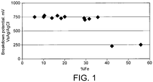
Figure 1 is a graph of published results showing the effect of dilution on the corrosion resistance of a weld overlay/cladding; -
Figure 2 is a schematic cross-sectional view of an apparatus according to one embodiment of the invention; -
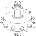
Figure 3 is an image of the cooling nozzle suitable for use in an embodiment of the invention; and -
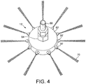
Figure 4 is an image of the cooling apparatus offigure 3 in use. - As seen in
Figure 1 , as the dilution of iron in the weld cladding increases the pitting corrosion resistance of the weld cladding significantly decreases. There is a significant step change in corrosion resistance after the threshold of 36% dilution of iron in the weld cladding. Fromfigure 1 it can be seen that a weld cladding having a dilution of less than 36% iron has a breakdown potential of approximately 750 mV. This breakdown potential drops dramatically when the weld cladding has a dilution of more than 36% iron.Figure 1 shows that the breakdown potential for weld claddings having a dilution of more than 36% is approximately 250 mV, this represent a reduction of approximately 66%. - As seen in
Figure 2 , a weld substrate 2 (which may for example be a pipe) has atop surface 4 and abottom surface 6. Awelding torch 8 is positioned above thetop surface 4 of theweld substrate 2. Thewelding torch 8 may for example be arranged for any one of Submerged Arc Welding(SAW), a Manual Metal Arc (MMA) welding, Gas Metal Arc Welding (GMAW), Flux Cored Arc Welding (FCAW), Gas Tungsten Arc welding (GTAW), Plasma Arc Welding (PAW) and laser welding. The skilled person will appreciate that the particular welding process chosen will depend upon the particular weld cladding application being performed. - A
coolant head 1 is provided at the reverse side of the substrate. Thecoolant head 1 comprises afirst cooling nozzle 10 and asecond cooling nozzle 12 each positioned below and directed towards thebottom surface 6 of theweld substrate 2. Thecoolant head 1 is generally axially aligned with thewelding torch 6. Thefirst cooling nozzle 10 is positioned slightly ahead of the weld deposition head, for example the nozzle may be approximately 10mm ahead of thewelding torch 8. Thesecond cooling nozzle 12 is downstream of thefirst nozzle 10 and of thewelding torch 8. At any period of time during the welding operation, the region of theweld substrate 2 which is impinged upon by the coolant may be arranged to be between 10 mm in front of and coaxial with thewelding torch 8. - The first and
second cooling nozzles inlets bottom surface 6 of theweld substrate 2. Theinlets nozzles outlets bottom surface 6 of theweld substrate 2. The stand-off distance of thenozzles 10" 12 from thebottom surface 6 of theweld substrate 2 is typically in the order of 10 mm to 50 mm. Thenozzle outlet nozzle outlet 30 may have an outlet diameter of less than 2mm. The nozzle outlet may have a outlet diameter of between 0.5mm and 2mm, for example 1.2 mm. - As known in the art, in use, the
welding torch 8 deposits theweld cladding 40 on thetop surface 4 of theweld substrate 2 at a deposition point in aweld deposition region 52. Thewelding torch 8 is moved relative to the substrate 2 (from right to left as shown by the arrow A inFigure 2 ). As thewelding torch 8 moves along the substrate the depositedweld cladding 40 solidifies and cools in aweld solidification region 54. - In accordance with the invention a
coolant head 1 is positioned below thesubstrate 2 on the reverse side with respect to thewelding torch 8. Thecoolant head 1 tracks the movement of thewelding torch 8 so as to maintain the alignment of thenozzles welding torch 8 andsubstrate 2. Simultaneously with respect to the weld deposition, liquid carbon dioxide is pumped into thecoolant head 1 throughinlets nozzles first cooling nozzle 10 cools the part of theweld substrate 2 which is directly ahead (or upstream) of thewelding torch 8 in order to affect maximum cooling efficiency in order to minimise weld dilution. Thesecond cooling nozzle 12 generally cools the part of theweld substrate 2 which is directly behind (i.e. downstream of) thewelding torch 8, where the weld is solidifying. It will be noted that the coolant impinges upon thesubstrate 2 and spreads along the longitudinal surface of thesubstrate 2 such that cryogenic coolant is spread across thebottom surface 6 from a point B ahead of thewelding torch 8 to a point B' which is behind thewelding torch 8. Thus coolant is distributed by thecoolant head 1 to thesubstrate 2 ahead of theweld region 52, in theweld region 52 and in thesolidification region 54. - The liquid carbon dioxide turns into solid
carbon dioxide snow 50, having a temperature of approximately -70 °C as it expands under pressure through theoutlets nozzles carbon dioxide snow 50 sublimes immediately on contact with thebottom surface 6 of theweld substrate 2. The flow rate of the carbon dioxide is dictated by the rate at which it is desired to cool the weld in order to reduce dilution. Typically, the mass flow rate of coolant may, for example, be up to 20 kg/min. The mass flow rate may be between 1 and 5 kg/min. - The rapid cooling of the
bottom surface 6 of theweld substrate 2 helps to manage the heat input into thesubstrate 2. This helps to limit the potential damage of the high heat input, and advantageously minimises weld dilution. -
Figures 3 and4 show a cooling nozzle 10' which is particularly suitable for use in acoolant head 1 according to embodiments of the invention in which thesubstrate 2 is a pipe. The nozzle 10' suitable for use in an embodiment of the invention can comprise abody portion 62 having twelve radially extending nozzle outlets 30'. The nozzles outlets 30' are evenly distributed about the circumference of thebody 62. The cooling nozzle 10' comprises aninlet 64 which has a threadedconnector 66 for receiving a pipe to provide a source of cryogenic coolant (not shown). - As seen in
figure 4 , in use theinlet 64 of the cooling nozzle 10' is connected to apipe 68 supplying liquid carbon dioxide. The liquid carbon dioxide is pumped out of the twelve radially extending nozzles outlets 30' under high pressure. Due to the even distribution of the nozzles outets 30' around the entire circumference of thebody 62 the cooling nozzle 10' ensures that coolant is delivered simultaneously and evenly to the entire internal circumferential surface of theweld 3. As the liquid carbon dioxide expands under pressure through the nozzle outlets 30' it transforms into solidcarbon dioxide snow 70. - Experiments were carried out to validate the suitability of a selection of jet nozzle outlets for use in embodiments of the invention. The jet nozzles were commercially available jet nozzles available from Amal (RTM).
Figures 5A and 5B show the cooling effect of carbon dioxide cryogenic coolant in Kilowatts for differing jet sizes (Figure 5A ) and at different flow rates (Figure 5B ). The relationship between cooling power and jet size was found to be non linear while the relationship between the cooling power and flow rate was linear.Figure 5C shows the relationship between the flow rate of coolant through different sized jet nozzles at a constant pressure. It will be noted that the relationship between the flow rate and nozzle size was found to be nonlinear. - According to the present invention, carbon dioxide has been found to have the highest heat transfer characteristics due to the immediate sublimation of the carbon dioxide snow upon contact with the hot weld surface. In contrast, other coolants may vaporise without contacting the weld surface.
Claims (11)
- A method of weld cladding comprising:a) providing a welding torch (8) adjacent a top surface (4) of a substrate (2);b) providing a coolant head (1) adjacent a bottom reverse, surface (6) of the substrate (2), wherein the coolant head (1) comprises at least one nozzle (10) for ejecting coolant (50) to impinge upon the bottom surface (6) of the substrate (2); andc) simultaneously depositing a weld (40) on the top surface (4) while applying a coolant (50) to the bottom surface (6) of the substrate (2);the weld (40) being of a material able to be diluted by the substrate (2), characterised in that the coolant (50) is cryogenic carbon dioxide.
- A method as claimed in claim 1, in which the coolant head (1) is substantially axially aligned with the welding torch (8) and is arranged to track the movement of the welding torch (8).
- A method according to claim 1 or 2, in which the cryogenic coolant (50) impinges upon the bottom surface (6) at or ahead of the point of deposition (52) of the weld (40).
- A method according to claim 3, in which the cryogenic coolant (50) impinges upon the bottom surface (6) between 0 and 20 mm ahead of the point of deposition (52) of the weld (40).
- A method according to any preceding claim, in which the coolant head (1) is arranged to apply a cryogenic coolant (50) to the bottom surface (6) of the substrate (2) in both a weld deposition region (52) and a weld solidification region (54).
- A method according to claim 5, in which the coolant head (1) comprises at least one cooling nozzle (10) for ejecting cryogenic coolant (50) to impinge upon the bottom surface (6) of the substrate (2) in the weld deposition region (52) and at least one further cooling nozzle (12) for ejecting cryogenic coolant (50) to impinge upon the bottom surface (6) of the substrate (2) in the weld solidification region (54).
- A method as claimed in any preceding claim, in which the cryogenic coolant (50) is solid carbon dioxide.
- A method as claimed in any preceding claims, in which the weld cladding (40) comprises stainless steel or high nickel alloy.
- A method as claimed in claim 8, in which the high nickel alloy is selected from alloy 625, alloy 825, alloy 725, alloy C276, alloy C22, alloy monel, alloy 905L, alloy 316L and alloy 304L.
- A method according to any preceding claim, wherein the substrate (2) is a pipe, the welding torch (8) is provided adjacent an outer surface of the pipe; and the coolant head (1) is provided adjacent an inner surface of the pipe.
- A method as claimed in any preceding claim, in which the coolant head (1) comprises at least one radial nozzle (30').
Priority Applications (1)
| Application Number | Priority Date | Filing Date | Title |
|---|---|---|---|
| PL12250091T PL2511037T3 (en) | 2011-04-13 | 2012-04-05 | A method of weld cladding with simultaneous deposition of weld on a side and cryogenic cooling on the opposite side ; Apparatus for performing such method |
Applications Claiming Priority (1)
| Application Number | Priority Date | Filing Date | Title |
|---|---|---|---|
| GBGB1106238.7A GB201106238D0 (en) | 2011-04-13 | 2011-04-13 | Weld cladding |
Publications (2)
| Publication Number | Publication Date |
|---|---|
| EP2511037A1 EP2511037A1 (en) | 2012-10-17 |
| EP2511037B1 true EP2511037B1 (en) | 2016-12-28 |
Family
ID=44123024
Family Applications (1)
| Application Number | Title | Priority Date | Filing Date |
|---|---|---|---|
| EP12250091.1A Not-in-force EP2511037B1 (en) | 2011-04-13 | 2012-04-05 | A method of weld cladding with simultaneous deposition of weld on a side and cryogenic cooling on the opposite side ; Apparatus for performing such method |
Country Status (4)
| Country | Link |
|---|---|
| EP (1) | EP2511037B1 (en) |
| GB (1) | GB201106238D0 (en) |
| HU (1) | HUE032631T2 (en) |
| PL (1) | PL2511037T3 (en) |
Cited By (3)
| Publication number | Priority date | Publication date | Assignee | Title |
|---|---|---|---|---|
| DE102016117914B4 (en) | 2016-09-22 | 2019-09-05 | Fraunhofer-Gesellschaft zur Förderung der angewandten Forschung e.V. | Method for producing a component or semifinished product and device for carrying out the same |
| FR3126899A1 (en) * | 2021-09-16 | 2023-03-17 | Psa Automobiles Sa | TREATMENT OF METALLIC PARTS BY MATERIAL DEPOSITION AND THERMAL CONTROL |
| US12233479B2 (en) | 2021-08-25 | 2025-02-25 | Purdue Research Foundation | Methods of enhancing surface hardness of quench-sensitive age-hardening materials, alloys produced therefrom, and laser cladding systems therefor |
Families Citing this family (6)
| Publication number | Priority date | Publication date | Assignee | Title |
|---|---|---|---|---|
| JP2018526220A (en) * | 2015-08-04 | 2018-09-13 | オートテック・エンジニアリング・アグルパシオン・デ・インテレス・エコノミコAutotech Engineering A.I.E. | Reinforced structural parts |
| DE102015117906B4 (en) * | 2015-10-21 | 2018-01-25 | Westfalen Ag | Method and device for producing metallic objects |
| WO2018054902A1 (en) * | 2016-09-20 | 2018-03-29 | Autotech Engineering Aie | Reinforcing structural components |
| GB2565083A (en) * | 2017-07-31 | 2019-02-06 | Linde Ag | Device and method for plasma cutting of work pieces |
| GB201712301D0 (en) * | 2017-07-31 | 2017-09-13 | Linde Ag | Method and device for plasma cutting of work pieces |
| CN120962128B (en) * | 2025-10-20 | 2025-12-26 | 西安卓锐航空科技有限公司 | Circumferential seam welding device and method for aviation pipeline parts |
Citations (4)
| Publication number | Priority date | Publication date | Assignee | Title |
|---|---|---|---|---|
| US4152568A (en) | 1975-08-08 | 1979-05-01 | Nippon Kokan Kabushiki Kaisha | Method of arc welding with reverse side cooling for obtaining highly tough large-diameter welded steel pipes |
| WO1988006505A1 (en) | 1987-02-28 | 1988-09-07 | Beijing Aeronautical Manufacturing Technology Rese | Improvements relating to welding |
| US4931232A (en) | 1987-09-21 | 1990-06-05 | L'air Liquide, Societe Anonyme Pour L'etude Et L'exploitation Des Procedes Georges Claude | Cooling process for a continuously extruded product |
| US5362937A (en) | 1991-04-18 | 1994-11-08 | Browne George W | Overlaying of plates |
Family Cites Families (5)
| Publication number | Priority date | Publication date | Assignee | Title |
|---|---|---|---|---|
| IT1089145B (en) * | 1977-12-23 | 1985-06-18 | Sio Ind Ossigeno Altri Gas | PROCEDURE AND RELATED EQUIPMENT FOR WELDING METAL SURFACES COATED WITH A VOLATILE ELEMENT WITH HEAT |
| FR2545007B1 (en) * | 1983-04-29 | 1986-12-26 | Commissariat Energie Atomique | METHOD AND DEVICE FOR COATING A WORKPIECE BY PLASMA SPRAYING |
| JPS62183985A (en) * | 1986-02-07 | 1987-08-12 | Nippon Kokan Kk <Nkk> | Laser crazing method |
| AU2363502A (en) * | 2000-10-24 | 2002-05-06 | Saipem Spa | Method and apparatus for welding pipes together |
| GB0124762D0 (en) * | 2001-10-16 | 2001-12-05 | Rolls Royce Plc | Apparatus and method for forming a body |
-
2011
- 2011-04-13 GB GBGB1106238.7A patent/GB201106238D0/en not_active Ceased
-
2012
- 2012-04-05 HU HUE12250091A patent/HUE032631T2/en unknown
- 2012-04-05 PL PL12250091T patent/PL2511037T3/en unknown
- 2012-04-05 EP EP12250091.1A patent/EP2511037B1/en not_active Not-in-force
Patent Citations (4)
| Publication number | Priority date | Publication date | Assignee | Title |
|---|---|---|---|---|
| US4152568A (en) | 1975-08-08 | 1979-05-01 | Nippon Kokan Kabushiki Kaisha | Method of arc welding with reverse side cooling for obtaining highly tough large-diameter welded steel pipes |
| WO1988006505A1 (en) | 1987-02-28 | 1988-09-07 | Beijing Aeronautical Manufacturing Technology Rese | Improvements relating to welding |
| US4931232A (en) | 1987-09-21 | 1990-06-05 | L'air Liquide, Societe Anonyme Pour L'etude Et L'exploitation Des Procedes Georges Claude | Cooling process for a continuously extruded product |
| US5362937A (en) | 1991-04-18 | 1994-11-08 | Browne George W | Overlaying of plates |
Cited By (3)
| Publication number | Priority date | Publication date | Assignee | Title |
|---|---|---|---|---|
| DE102016117914B4 (en) | 2016-09-22 | 2019-09-05 | Fraunhofer-Gesellschaft zur Förderung der angewandten Forschung e.V. | Method for producing a component or semifinished product and device for carrying out the same |
| US12233479B2 (en) | 2021-08-25 | 2025-02-25 | Purdue Research Foundation | Methods of enhancing surface hardness of quench-sensitive age-hardening materials, alloys produced therefrom, and laser cladding systems therefor |
| FR3126899A1 (en) * | 2021-09-16 | 2023-03-17 | Psa Automobiles Sa | TREATMENT OF METALLIC PARTS BY MATERIAL DEPOSITION AND THERMAL CONTROL |
Also Published As
| Publication number | Publication date |
|---|---|
| EP2511037A1 (en) | 2012-10-17 |
| PL2511037T3 (en) | 2017-06-30 |
| GB201106238D0 (en) | 2011-05-25 |
| HUE032631T2 (en) | 2018-06-28 |
Similar Documents
| Publication | Publication Date | Title |
|---|---|---|
| EP2511037A1 (en) | A method of weld cladding with simultaneous deposition of weld on a side and cryogenic cooling on the opposite side ; Apparatus for performing such method | |
| JP5039043B2 (en) | Plasma torch having corrosion-resistant collimator nozzle and method for manufacturing the nozzle | |
| JP5320196B2 (en) | Dissimilar material overlay welding method and dissimilar material overlay welded structure | |
| JP5851136B2 (en) | Cooling device and cooling method for metal tube after heating | |
| US11110546B2 (en) | Laser hot wire welding of multi-layered structures | |
| CN110114179B (en) | Field formers for welding applications | |
| JP2010508155A (en) | Automatic underwater welding apparatus and automatic underwater welding method for making a welded joint on a surface | |
| US6069334A (en) | Electroslag strip overlay method | |
| US5705786A (en) | Underwater welding | |
| CN114515886A (en) | Large-size special-shaped stainless steel pipeline and efficient additive manufacturing device and method thereof | |
| JP5896995B2 (en) | Method for manufacturing a clad tube and clad tube | |
| El-Batahgy | Laser beam welding of austenitic stainless steels–Similar butt and dissimilar lap joints | |
| Gladkii et al. | Plasma surfacing | |
| US20050092813A1 (en) | Flux assisted gas tungsten arc welding utilizing consumable inserts for ultra low profile welding applications | |
| US12275087B2 (en) | Method for welding sheets with coatings comprising an alloy of aluminum and silicon | |
| EP3481578B1 (en) | Fluid-cooled contact tip assembly for metal welding | |
| EP2678135B1 (en) | Equipment for cold-cleaning of welding torches | |
| Kay | Thermal spray applications in the steel industry | |
| EP4378616A1 (en) | Segmented shielding gas trailing nozzle | |
| Egerland | Status and perspectives in overlaying under particular consideration of sophisticated welding processes | |
| RU213469U1 (en) | PLASMATRON FOR ADDITIVE GROWING | |
| RU2744885C1 (en) | Methods and apparatus for welding using electrodes with coaxial power supply | |
| Kim et al. | Bead Surface Characteristics from Powder Feeding Conditions During Laser Cladding with Diode Laser | |
| JP2019217540A (en) | Cast piece scarfing device and cast piece scarfing method | |
| Ali et al. | Laser-assisted GMAW hardfacing |
Legal Events
| Date | Code | Title | Description |
|---|---|---|---|
| PUAI | Public reference made under article 153(3) epc to a published international application that has entered the european phase |
Free format text: ORIGINAL CODE: 0009012 |
|
| AK | Designated contracting states |
Kind code of ref document: A1 Designated state(s): AL AT BE BG CH CY CZ DE DK EE ES FI FR GB GR HR HU IE IS IT LI LT LU LV MC MK MT NL NO PL PT RO RS SE SI SK SM TR |
|
| AX | Request for extension of the european patent |
Extension state: BA ME |
|
| 17P | Request for examination filed |
Effective date: 20130416 |
|
| 17Q | First examination report despatched |
Effective date: 20131113 |
|
| REG | Reference to a national code |
Ref country code: DE Ref legal event code: R079 Ref document number: 602012027047 Country of ref document: DE Free format text: PREVIOUS MAIN CLASS: B23K0009040000 Ipc: B23K0009180000 |
|
| RIC1 | Information provided on ipc code assigned before grant |
Ipc: B23K 26/14 20060101ALI20160825BHEP Ipc: B23K 9/18 20060101AFI20160825BHEP Ipc: B23K 9/32 20060101ALI20160825BHEP Ipc: B23K 9/16 20060101ALI20160825BHEP Ipc: B23K 26/70 20140101ALI20160825BHEP Ipc: B23K 26/34 20140101ALI20160825BHEP Ipc: B23K 10/02 20060101ALI20160825BHEP Ipc: B23K 9/04 20060101ALI20160825BHEP |
|
| GRAP | Despatch of communication of intention to grant a patent |
Free format text: ORIGINAL CODE: EPIDOSNIGR1 |
|
| INTG | Intention to grant announced |
Effective date: 20161006 |
|
| GRAS | Grant fee paid |
Free format text: ORIGINAL CODE: EPIDOSNIGR3 |
|
| GRAA | (expected) grant |
Free format text: ORIGINAL CODE: 0009210 |
|
| AK | Designated contracting states |
Kind code of ref document: B1 Designated state(s): AL AT BE BG CH CY CZ DE DK EE ES FI FR GB GR HR HU IE IS IT LI LT LU LV MC MK MT NL NO PL PT RO RS SE SI SK SM TR |
|
| REG | Reference to a national code |
Ref country code: GB Ref legal event code: FG4D |
|
| REG | Reference to a national code |
Ref country code: CH Ref legal event code: EP |
|
| REG | Reference to a national code |
Ref country code: AT Ref legal event code: REF Ref document number: 856863 Country of ref document: AT Kind code of ref document: T Effective date: 20170115 |
|
| REG | Reference to a national code |
Ref country code: IE Ref legal event code: FG4D |
|
| REG | Reference to a national code |
Ref country code: DE Ref legal event code: R096 Ref document number: 602012027047 Country of ref document: DE |
|
| PG25 | Lapsed in a contracting state [announced via postgrant information from national office to epo] |
Ref country code: LV Free format text: LAPSE BECAUSE OF FAILURE TO SUBMIT A TRANSLATION OF THE DESCRIPTION OR TO PAY THE FEE WITHIN THE PRESCRIBED TIME-LIMIT Effective date: 20161228 |
|
| REG | Reference to a national code |
Ref country code: RO Ref legal event code: EPE |
|
| REG | Reference to a national code |
Ref country code: SE Ref legal event code: TRGR |
|
| REG | Reference to a national code |
Ref country code: LT Ref legal event code: MG4D |
|
| PG25 | Lapsed in a contracting state [announced via postgrant information from national office to epo] |
Ref country code: LT Free format text: LAPSE BECAUSE OF FAILURE TO SUBMIT A TRANSLATION OF THE DESCRIPTION OR TO PAY THE FEE WITHIN THE PRESCRIBED TIME-LIMIT Effective date: 20161228 Ref country code: GR Free format text: LAPSE BECAUSE OF FAILURE TO SUBMIT A TRANSLATION OF THE DESCRIPTION OR TO PAY THE FEE WITHIN THE PRESCRIBED TIME-LIMIT Effective date: 20170329 |
|
| REG | Reference to a national code |
Ref country code: NL Ref legal event code: MP Effective date: 20161228 |
|
| REG | Reference to a national code |
Ref country code: AT Ref legal event code: MK05 Ref document number: 856863 Country of ref document: AT Kind code of ref document: T Effective date: 20161228 |
|
| REG | Reference to a national code |
Ref country code: NO Ref legal event code: T2 Effective date: 20161228 |
|
| PG25 | Lapsed in a contracting state [announced via postgrant information from national office to epo] |
Ref country code: RS Free format text: LAPSE BECAUSE OF FAILURE TO SUBMIT A TRANSLATION OF THE DESCRIPTION OR TO PAY THE FEE WITHIN THE PRESCRIBED TIME-LIMIT Effective date: 20161228 Ref country code: HR Free format text: LAPSE BECAUSE OF FAILURE TO SUBMIT A TRANSLATION OF THE DESCRIPTION OR TO PAY THE FEE WITHIN THE PRESCRIBED TIME-LIMIT Effective date: 20161228 Ref country code: FI Free format text: LAPSE BECAUSE OF FAILURE TO SUBMIT A TRANSLATION OF THE DESCRIPTION OR TO PAY THE FEE WITHIN THE PRESCRIBED TIME-LIMIT Effective date: 20161228 |
|
| PG25 | Lapsed in a contracting state [announced via postgrant information from national office to epo] |
Ref country code: NL Free format text: LAPSE BECAUSE OF FAILURE TO SUBMIT A TRANSLATION OF THE DESCRIPTION OR TO PAY THE FEE WITHIN THE PRESCRIBED TIME-LIMIT Effective date: 20161228 |
|
| PG25 | Lapsed in a contracting state [announced via postgrant information from national office to epo] |
Ref country code: IS Free format text: LAPSE BECAUSE OF FAILURE TO SUBMIT A TRANSLATION OF THE DESCRIPTION OR TO PAY THE FEE WITHIN THE PRESCRIBED TIME-LIMIT Effective date: 20170428 Ref country code: SK Free format text: LAPSE BECAUSE OF FAILURE TO SUBMIT A TRANSLATION OF THE DESCRIPTION OR TO PAY THE FEE WITHIN THE PRESCRIBED TIME-LIMIT Effective date: 20161228 Ref country code: EE Free format text: LAPSE BECAUSE OF FAILURE TO SUBMIT A TRANSLATION OF THE DESCRIPTION OR TO PAY THE FEE WITHIN THE PRESCRIBED TIME-LIMIT Effective date: 20161228 |
|
| PG25 | Lapsed in a contracting state [announced via postgrant information from national office to epo] |
Ref country code: AT Free format text: LAPSE BECAUSE OF FAILURE TO SUBMIT A TRANSLATION OF THE DESCRIPTION OR TO PAY THE FEE WITHIN THE PRESCRIBED TIME-LIMIT Effective date: 20161228 Ref country code: PT Free format text: LAPSE BECAUSE OF FAILURE TO SUBMIT A TRANSLATION OF THE DESCRIPTION OR TO PAY THE FEE WITHIN THE PRESCRIBED TIME-LIMIT Effective date: 20170428 Ref country code: BG Free format text: LAPSE BECAUSE OF FAILURE TO SUBMIT A TRANSLATION OF THE DESCRIPTION OR TO PAY THE FEE WITHIN THE PRESCRIBED TIME-LIMIT Effective date: 20170328 Ref country code: BE Free format text: LAPSE BECAUSE OF FAILURE TO SUBMIT A TRANSLATION OF THE DESCRIPTION OR TO PAY THE FEE WITHIN THE PRESCRIBED TIME-LIMIT Effective date: 20161228 Ref country code: SM Free format text: LAPSE BECAUSE OF FAILURE TO SUBMIT A TRANSLATION OF THE DESCRIPTION OR TO PAY THE FEE WITHIN THE PRESCRIBED TIME-LIMIT Effective date: 20161228 Ref country code: ES Free format text: LAPSE BECAUSE OF FAILURE TO SUBMIT A TRANSLATION OF THE DESCRIPTION OR TO PAY THE FEE WITHIN THE PRESCRIBED TIME-LIMIT Effective date: 20161228 |
|
| REG | Reference to a national code |
Ref country code: DE Ref legal event code: R026 Ref document number: 602012027047 Country of ref document: DE |
|
| PLBI | Opposition filed |
Free format text: ORIGINAL CODE: 0009260 |
|
| 26 | Opposition filed |
Opponent name: L'AIR LIQUIDE SOCIETE ANONYME POUR L'ETUDE ET L'EX Effective date: 20170926 |
|
| PLAX | Notice of opposition and request to file observation + time limit sent |
Free format text: ORIGINAL CODE: EPIDOSNOBS2 |
|
| PG25 | Lapsed in a contracting state [announced via postgrant information from national office to epo] |
Ref country code: DK Free format text: LAPSE BECAUSE OF FAILURE TO SUBMIT A TRANSLATION OF THE DESCRIPTION OR TO PAY THE FEE WITHIN THE PRESCRIBED TIME-LIMIT Effective date: 20161228 |
|
| REG | Reference to a national code |
Ref country code: CH Ref legal event code: PL |
|
| REG | Reference to a national code |
Ref country code: IE Ref legal event code: MM4A |
|
| REG | Reference to a national code |
Ref country code: FR Ref legal event code: ST Effective date: 20171229 |
|
| PG25 | Lapsed in a contracting state [announced via postgrant information from national office to epo] |
Ref country code: FR Free format text: LAPSE BECAUSE OF NON-PAYMENT OF DUE FEES Effective date: 20170502 Ref country code: MC Free format text: LAPSE BECAUSE OF FAILURE TO SUBMIT A TRANSLATION OF THE DESCRIPTION OR TO PAY THE FEE WITHIN THE PRESCRIBED TIME-LIMIT Effective date: 20161228 |
|
| PG25 | Lapsed in a contracting state [announced via postgrant information from national office to epo] |
Ref country code: LU Free format text: LAPSE BECAUSE OF NON-PAYMENT OF DUE FEES Effective date: 20170405 Ref country code: LI Free format text: LAPSE BECAUSE OF NON-PAYMENT OF DUE FEES Effective date: 20170430 Ref country code: CH Free format text: LAPSE BECAUSE OF NON-PAYMENT OF DUE FEES Effective date: 20170430 Ref country code: SI Free format text: LAPSE BECAUSE OF FAILURE TO SUBMIT A TRANSLATION OF THE DESCRIPTION OR TO PAY THE FEE WITHIN THE PRESCRIBED TIME-LIMIT Effective date: 20161228 |
|
| PLBB | Reply of patent proprietor to notice(s) of opposition received |
Free format text: ORIGINAL CODE: EPIDOSNOBS3 |
|
| PG25 | Lapsed in a contracting state [announced via postgrant information from national office to epo] |
Ref country code: IE Free format text: LAPSE BECAUSE OF NON-PAYMENT OF DUE FEES Effective date: 20170405 |
|
| REG | Reference to a national code |
Ref country code: HU Ref legal event code: AG4A Ref document number: E032631 Country of ref document: HU |
|
| PG25 | Lapsed in a contracting state [announced via postgrant information from national office to epo] |
Ref country code: MT Free format text: LAPSE BECAUSE OF NON-PAYMENT OF DUE FEES Effective date: 20170405 |
|
| REG | Reference to a national code |
Ref country code: DE Ref legal event code: R100 Ref document number: 602012027047 Country of ref document: DE |
|
| PLCK | Communication despatched that opposition was rejected |
Free format text: ORIGINAL CODE: EPIDOSNREJ1 |
|
| PGFP | Annual fee paid to national office [announced via postgrant information from national office to epo] |
Ref country code: IT Payment date: 20190419 Year of fee payment: 8 Ref country code: NO Payment date: 20190409 Year of fee payment: 8 Ref country code: DE Payment date: 20190326 Year of fee payment: 8 |
|
| PGFP | Annual fee paid to national office [announced via postgrant information from national office to epo] |
Ref country code: HR Payment date: 20190614 Year of fee payment: 8 |
|
| PLBN | Opposition rejected |
Free format text: ORIGINAL CODE: 0009273 |
|
| STAA | Information on the status of an ep patent application or granted ep patent |
Free format text: STATUS: OPPOSITION REJECTED |
|
| 27O | Opposition rejected |
Effective date: 20190402 |
|
| PG25 | Lapsed in a contracting state [announced via postgrant information from national office to epo] |
Ref country code: CY Free format text: LAPSE BECAUSE OF NON-PAYMENT OF DUE FEES Effective date: 20161228 |
|
| PGFP | Annual fee paid to national office [announced via postgrant information from national office to epo] |
Ref country code: GB Payment date: 20190403 Year of fee payment: 8 |
|
| PG25 | Lapsed in a contracting state [announced via postgrant information from national office to epo] |
Ref country code: MK Free format text: LAPSE BECAUSE OF FAILURE TO SUBMIT A TRANSLATION OF THE DESCRIPTION OR TO PAY THE FEE WITHIN THE PRESCRIBED TIME-LIMIT Effective date: 20161228 |
|
| PG25 | Lapsed in a contracting state [announced via postgrant information from national office to epo] |
Ref country code: TR Free format text: LAPSE BECAUSE OF FAILURE TO SUBMIT A TRANSLATION OF THE DESCRIPTION OR TO PAY THE FEE WITHIN THE PRESCRIBED TIME-LIMIT Effective date: 20161228 |
|
| PGFP | Annual fee paid to national office [announced via postgrant information from national office to epo] |
Ref country code: PL Payment date: 20200326 Year of fee payment: 9 Ref country code: RO Payment date: 20200323 Year of fee payment: 9 |
|
| PGFP | Annual fee paid to national office [announced via postgrant information from national office to epo] |
Ref country code: CZ Payment date: 20200319 Year of fee payment: 9 |
|
| REG | Reference to a national code |
Ref country code: DE Ref legal event code: R081 Ref document number: 602012027047 Country of ref document: DE Owner name: LINDE GMBH, DE Free format text: FORMER OWNER: LINDE AKTIENGESELLSCHAFT, 80331 MUENCHEN, DE |
|
| PG25 | Lapsed in a contracting state [announced via postgrant information from national office to epo] |
Ref country code: AL Free format text: LAPSE BECAUSE OF FAILURE TO SUBMIT A TRANSLATION OF THE DESCRIPTION OR TO PAY THE FEE WITHIN THE PRESCRIBED TIME-LIMIT Effective date: 20161228 |
|
| PGFP | Annual fee paid to national office [announced via postgrant information from national office to epo] |
Ref country code: HU Payment date: 20200320 Year of fee payment: 9 |
|
| REG | Reference to a national code |
Ref country code: DE Ref legal event code: R119 Ref document number: 602012027047 Country of ref document: DE |
|
| REG | Reference to a national code |
Ref country code: NO Ref legal event code: MMEP |
|
| PG25 | Lapsed in a contracting state [announced via postgrant information from national office to epo] |
Ref country code: NO Free format text: LAPSE BECAUSE OF NON-PAYMENT OF DUE FEES Effective date: 20200430 Ref country code: DE Free format text: LAPSE BECAUSE OF NON-PAYMENT OF DUE FEES Effective date: 20201103 Ref country code: SE Free format text: LAPSE BECAUSE OF NON-PAYMENT OF DUE FEES Effective date: 20200406 |
|
| GBPC | Gb: european patent ceased through non-payment of renewal fee |
Effective date: 20200405 |
|
| PG25 | Lapsed in a contracting state [announced via postgrant information from national office to epo] |
Ref country code: GB Free format text: LAPSE BECAUSE OF NON-PAYMENT OF DUE FEES Effective date: 20200405 |
|
| PG25 | Lapsed in a contracting state [announced via postgrant information from national office to epo] |
Ref country code: IT Free format text: LAPSE BECAUSE OF NON-PAYMENT OF DUE FEES Effective date: 20200405 Ref country code: CZ Free format text: LAPSE BECAUSE OF NON-PAYMENT OF DUE FEES Effective date: 20210405 |
|
| PG25 | Lapsed in a contracting state [announced via postgrant information from national office to epo] |
Ref country code: HU Free format text: LAPSE BECAUSE OF NON-PAYMENT OF DUE FEES Effective date: 20210406 Ref country code: RO Free format text: LAPSE BECAUSE OF NON-PAYMENT OF DUE FEES Effective date: 20210405 |
|
| PG25 | Lapsed in a contracting state [announced via postgrant information from national office to epo] |
Ref country code: PL Free format text: LAPSE BECAUSE OF NON-PAYMENT OF DUE FEES Effective date: 20210405 |