EP2510878A1 - Verfahren zur Generierung einer radiologischen dreidimensionalen digitalen Volumentomographie-Aufnahme eines Patienten-Körperteils - Google Patents
Verfahren zur Generierung einer radiologischen dreidimensionalen digitalen Volumentomographie-Aufnahme eines Patienten-Körperteils Download PDFInfo
- Publication number
- EP2510878A1 EP2510878A1 EP11162043A EP11162043A EP2510878A1 EP 2510878 A1 EP2510878 A1 EP 2510878A1 EP 11162043 A EP11162043 A EP 11162043A EP 11162043 A EP11162043 A EP 11162043A EP 2510878 A1 EP2510878 A1 EP 2510878A1
- Authority
- EP
- European Patent Office
- Prior art keywords
- body part
- generating
- patient
- marker
- raw image
- Prior art date
- Legal status (The legal status is an assumption and is not a legal conclusion. Google has not performed a legal analysis and makes no representation as to the accuracy of the status listed.)
- Granted
Links
Images
Classifications
-
- A—HUMAN NECESSITIES
- A61—MEDICAL OR VETERINARY SCIENCE; HYGIENE
- A61B—DIAGNOSIS; SURGERY; IDENTIFICATION
- A61B6/00—Apparatus or devices for radiation diagnosis; Apparatus or devices for radiation diagnosis combined with radiation therapy equipment
- A61B6/46—Arrangements for interfacing with the operator or the patient
- A61B6/461—Displaying means of special interest
- A61B6/466—Displaying means of special interest adapted to display 3D data
-
- A—HUMAN NECESSITIES
- A61—MEDICAL OR VETERINARY SCIENCE; HYGIENE
- A61B—DIAGNOSIS; SURGERY; IDENTIFICATION
- A61B6/00—Apparatus or devices for radiation diagnosis; Apparatus or devices for radiation diagnosis combined with radiation therapy equipment
- A61B6/12—Arrangements for detecting or locating foreign bodies
-
- A—HUMAN NECESSITIES
- A61—MEDICAL OR VETERINARY SCIENCE; HYGIENE
- A61B—DIAGNOSIS; SURGERY; IDENTIFICATION
- A61B6/00—Apparatus or devices for radiation diagnosis; Apparatus or devices for radiation diagnosis combined with radiation therapy equipment
- A61B6/50—Apparatus or devices for radiation diagnosis; Apparatus or devices for radiation diagnosis combined with radiation therapy equipment specially adapted for specific body parts; specially adapted for specific clinical applications
- A61B6/51—Apparatus or devices for radiation diagnosis; Apparatus or devices for radiation diagnosis combined with radiation therapy equipment specially adapted for specific body parts; specially adapted for specific clinical applications for dentistry
-
- A—HUMAN NECESSITIES
- A61—MEDICAL OR VETERINARY SCIENCE; HYGIENE
- A61B—DIAGNOSIS; SURGERY; IDENTIFICATION
- A61B6/00—Apparatus or devices for radiation diagnosis; Apparatus or devices for radiation diagnosis combined with radiation therapy equipment
- A61B6/58—Testing, adjusting or calibrating thereof
- A61B6/582—Calibration
- A61B6/583—Calibration using calibration phantoms
-
- G—PHYSICS
- G06—COMPUTING OR CALCULATING; COUNTING
- G06T—IMAGE DATA PROCESSING OR GENERATION, IN GENERAL
- G06T12/00—Tomographic reconstruction from projections
- G06T12/30—Image post-processing, e.g. metal artefact correction
-
- G—PHYSICS
- G06—COMPUTING OR CALCULATING; COUNTING
- G06T—IMAGE DATA PROCESSING OR GENERATION, IN GENERAL
- G06T3/00—Geometric image transformations in the plane of the image
- G06T3/40—Scaling of whole images or parts thereof, e.g. expanding or contracting
Definitions
- the invention relates to a method for generating a radiological three-dimensional digital volume tomography image of a patient's body part, in particular a patient's head, and in this case particularly preferably a patient's jaw.
- digital volume tomography is often used.
- a cone-shaped x-ray beam is directed at a two-dimensional detector which is opposed at a constant distance.
- the assembly consisting of the X-ray source and the detector, is moved around the patient's head during the recording, taking 10-30 seconds to record.
- Digital volume tomography has the advantage of relatively low radiation exposure to the patient compared to other three-dimensional radiographic imaging techniques.
- the quality of the resulting three-dimensional images of the patient's head is highly variable and difficult to assess.
- the reasons for the fluctuating image quality are on the one hand inherent in principle and physical nature, and are on the other hand in the long recording duration, because of unwanted intrinsic movements of the patient's head, the X-ray source and the detector during the recording can not be excluded. Due to the proper movements, the quality of the images is considerably worsened.
- the size relationships and relationships are often represented with an error of up to several millimeters. Although this is not always problematic in diagnostics, digital volume tomography becomes particularly used in dentistry for the planning of dental implants in the patient's jaw. In this case, a high geometric accuracy is required in order to ensure a high quality of the implant supply can.
- the object of the invention is in contrast to provide a method for generating a radiological three-dimensional recording, in particular a digital volume tomography recording of a patient's body part with the possibility of quality control and / or improved accuracy.
- a label carrier is fixed to the patient's body part, and preferably in the patient's mouth.
- the marker carrier can have an individual molded part shaped from the patient's jaw, with which the marker carrier can be placed on the patient's jaw in a form-fitting and immovable manner. The fixation can be done by the bite of the patient.
- the marker carrier has a non-radiopaque carrier body which absorbs virtually no X-ray radiation and is therefore largely invisible to an X-ray machine.
- a plurality of radio-opaque marker elements are fixed, the actual size S and / or actual distance D is known to each other.
- a recording of the relevant body part is made with the digital volume tomography device to produce a three-dimensional raw image of the body part, as is already known from the prior art.
- the digital volume tomography device to produce a three-dimensional raw image of the body part, as is already known from the prior art.
- their size S 'and / or the distances D' of the marker elements are measured relative to one another in the raw image.
- the measured values for the marker element size S 'or the marker element distances D' are compared with the respective actual values S, D, and from this a matching value QS, QD is generated.
- this adjustment value QS, QD can be the quotient of the respective actual value S, D and the measured values S ', D'.
- the raw image is corrected on the basis of the obtained matching values QS, QD.
- the raw image can be normalized, for example, by being stretched or compressed by the value of the quotient of the actual value and the measured value.
- the thus obtained corrected three-dimensional image of the body part or the patient's jaw is considerably more accurate than the raw image, in particular with regard to the size ratios and distances.
- an exact three-dimensional image of the patient's jaw is made available in this way, which forms the basis for the subsequent precise planning and realization of the implantological dental restoration.
- the correction is a size correction of the raw image based on the raw image distances D 'in relation to the actual distances D of the marker elements to each other. From the quotient of the raw image distances D 'and the actual distances D of the marker elements to one another, a correction value can be generated directly by which the raw image is to be corrected.
- a quality indicator can be output whose value results from the deviation of the raw image size S 'in relation to the actual size S of the marker elements.
- a quotient can also be used here.
- the size-quality indicator provides information about the quality of the raw image at the location of the respective marker element. In case of blurring or blurring in the raw image, the marker element in the raw image, for example, represented considerably larger than it actually is. Although no immediate correction of the raw image can be performed with the help of the quality indicator, it does give the user
- the raw image provides information about the extent to which the user can trust the raw image.
- each marker element being arranged to its neighboring marker elements in each case at a constant actual distance of at most 3.0 cm.
- the mesh size over the entire network is always the same, and the mesh size is at most 3.0 cm.
- the marker elements can each be distributed flat or in space and arranged on perpendicular lines to each other. However, three adjacent marker elements particularly preferably form an equilateral triangle. With this arrangement, with relatively few marker elements, which in principle can also be the source of artifacts because of their radio opacity, a network with a sufficient density of marker elements in the relevant space can be spanned.
- the marker elements are arranged in at least two transverse planes, ie in two horizontal planes. This ensures that the size correction of the raw image on the basis of the distances D, D 'of the marker elements to each other can be made with respect to all three spatial axes.
- the radioopacity of the marker elements is different. Since the marker elements also have reflexive properties due to their radio-opacity with respect to the X-ray radiation, artifacts in these areas can be reduced or avoided, for example, by reducing the radioopacity of the marker elements in particularly sensitive areas.
- the radioopotential values of the marker elements may have three to six different values, so that approximately the entire radioopotential spectrum of the part of the body to be photographed is covered.
- This provides an objective measure of radio opacity in the raw image.
- the raw image can be automatically calibrated, i.
- the structures of the body part depicted in the raw image can be classified objectively with respect to their radioopacity. This facilitates the interpretation of the three-dimensional image.
- bone and tissue can be distinguished easier and safer from each other, which is of essential importance in dental implantology.
- the marker carrier can have a plurality of radioopacity spectra distributed over the body part or the image space, each consisting of a plurality of marker elements of different radio opacity, so that the calibration can be carried out locally. This can take into account the fact that the imaging quality in the digital volume tomography principle can turn out locally very different.
- the label carrier is designed as an intraoral marker carrier, and a plurality of marker elements are arranged within the dental arch.
- a plurality of marker elements are arranged within the dental arch.
- at least one marker element is arranged outside the dental arch, and particularly preferably outside the patient's mouth.
- the arrangement outside the dental arch or the patient's mouth allows the generation of adjustment values, for example in the region of the jawbone of the patient's jaw. Especially in this area, high accuracy is desirable for implant planning.
- the embodiments illustrated in the figures relate to a dental application, wherein the body part in the present case is a patient's jaw.
- an intraoral marker carrier 10 is shown, as it is suitable for generating a radiological three-dimensional recording with a digital volume tomography device.
- the marker carrier 10 consists of a radiologically invisible support body 12 made of a suitable plastic.
- On the support body 12, an individual molded part 16 is attached, for example glued, the tooth recesses 18 which are complementary to the patient teeth 24 formed.
- the individual molded part 16 which represents an impression of the respective patient's jaw 22, 23, a firm, immovable and defined seat of the marker carrier 10 on the patient's jaw 22, 23 in the patient's mouth is ensured.
- marker elements 14 lying in two planes and evenly distributed. Three mutually adjacent marker elements 14 each form an equilateral triangle, and are each spaced with a same distance for all marker elements 14 actual distance D, which is not greater than 3.0 cm. All marker elements 14 have an identical size S, which corresponds to the diameter, for example, in the case of spherical marker elements 14. The size S is a maximum of a few millimeters.
- a second embodiment of a more complex marker carrier 20 is shown, which is inserted into the patient's mouth.
- a rotatable about a vertical axis rotor 44 of a digital volume tomography device which carries an X-ray source 40 which generates a cone-shaped X-ray beam, and opposite a two-dimensional detector 42.
- the marker carrier 20 is H-shaped in cross-section and has a horizontal carrier body part 26 and on its outer circumference each upwardly and downwardly projecting vertical carrier body parts 30,32.
- the marker elements 14 are distributed in a planar manner.
- an individual shaped part 28, 29 is respectively fixed, which is shaped by the upper jaw 22 and the lower jaw 23.
- the arrangement of the marker elements 14 corresponds in principle to that in the marker carrier 10 of Figures 1 and 2 ,
- the label carriers 14 in the horizontal carrier body portion 26 are disposed within the dental arches 36, 37 spanned by the patient teeth 24 of the patient upper jaw 22 and lower jaw 23.
- the marker elements 14 'in the vertical support body parts 30, 32 are arranged outside the dental arches 36, 37 but within the patient's mouth.
- a recording of the patient's jaw for generating a three-dimensional raw image of the patient's head or jaw is made in the next method step 52 with the digital volume tomography device.
- a further method step 54 in FIG Measure the raw image with respect to all marker elements of their size S 'and the distances D' of the marker elements to each other.
- the measured values for the marker element distances D ' are compared with the known actual value D, or a quotient is generated therefrom.
- a correction value QD is generated directly in order to locally correct the raw image in a subsequent method step 58.
- the correction is in each case a size correction of the raw image on the basis of the raw image distances D 'in relation to the actual stocks D of the marker elements to each other.
- the thus obtained three-dimensional corrected image of the patient's head or the patient's jaw is considerably more accurate, in particular with regard to the size ratios and distances, than the raw image.
- an exact three-dimensional image of the patient's jaw is made available in this way, which forms the basis for the subsequent precise planning and realization of the implantological dental restoration.
- the size-quality indicator QS provides information about the quality of the raw image at the location concerned, and in particular provides information on the extent to which the raw image or the corrected raw image can be trusted.
- the radioopacity of the marker elements 14,14 ' is different.
- a spectrum of three to six mutually adjacent marker elements 14 'of different radio opacity can be provided on the vertical support body part 30 at four positions of the dental arch. These are used in the raw image, the raw image in terms of its brightness and its contrast each to be calibrated locally. This calibration can be quite different in the four areas. The resulting image significantly facilitates the differentiation of bone and tissue.
Landscapes
- Health & Medical Sciences (AREA)
- Life Sciences & Earth Sciences (AREA)
- Engineering & Computer Science (AREA)
- Medical Informatics (AREA)
- Physics & Mathematics (AREA)
- Pathology (AREA)
- Molecular Biology (AREA)
- Biophysics (AREA)
- High Energy & Nuclear Physics (AREA)
- Veterinary Medicine (AREA)
- Nuclear Medicine, Radiotherapy & Molecular Imaging (AREA)
- Optics & Photonics (AREA)
- Public Health (AREA)
- Radiology & Medical Imaging (AREA)
- Biomedical Technology (AREA)
- Heart & Thoracic Surgery (AREA)
- General Health & Medical Sciences (AREA)
- Surgery (AREA)
- Animal Behavior & Ethology (AREA)
- General Physics & Mathematics (AREA)
- Theoretical Computer Science (AREA)
- Human Computer Interaction (AREA)
- Dentistry (AREA)
- Oral & Maxillofacial Surgery (AREA)
- Apparatus For Radiation Diagnosis (AREA)
- Dental Tools And Instruments Or Auxiliary Dental Instruments (AREA)
Abstract
Description
- Die Erfindung bezieht sich auf ein Verfahren zur Generierung einer radiologischen dreidimensionalen digitalen Volumentomographie-Aufnahme eines Patienten-Körperteils, insbesondere eines Patientenkopfes, und hierbei besonders bevorzugt eines Patientenkiefers. Als zahnärztliches und hals-nasen-ohrenärztliches bildgebendes radiologisches Tomographie-Verfahren wird häufig die digitale Volumentomographie eingesetzt. Bei der digitalen Volumentomographie wird ein kegelförmiger Röntgenstrahl auf einen in einem konstanten Abstand gegenüberstehenden zweidimensionalen Detektor gerichtet. Die Anordnung, bestehend aus der Röntgenstrahlungsquelle und dem Detektor, wird während der Aufnahme um den Patientenkopf herum bewegt, wobei für eine Aufnahme 10-30 s benötigt werden.
- Die digitale Volumentomographie hat, im Vergleich zu anderen dreidimensionalen bildgebenden radiologischen Verfahren, den Vorteil einer relativ geringen Strahlenbelastung für den Patienten. Allerdings ist die Qualität der hieraus gewonnenen und errechneten dreidimensionalen Bilder des Patientenkopfes stark schwankend, und ist nur schwer einzuschätzen. Die Gründe für die schwankende Bildqualität sind zum Einen prinzipbedingt und physikalischer Natur, und liegen zum Anderen in der langen Aufnahme-Dauer, wegen der unerwünschte Eigenbewegungen des Patientenkopfes, der Röntgenstrahlungsquelle und des Detektors während der Aufnahme nicht ausgeschlossen werden können. Durch die Eigenbewegungen wird die Qualität der Bilder erheblich verschlechtert. In der Praxis werden in dem dreidimensionalen Bild die Größenverhältnisse und -relationen häufig mit einem Fehler von bis zu mehreren Millimetern dargestellt, Dies ist zwar in der Diagnostik nicht in jedem Fall problematisch, jedoch wird die digitale Volumentomographie insbesondere in der Zahnheilkunde zur Planung von dentalen Implantaten im Patientenkiefer eingesetzt. Hierbei ist eine hohe geometrische Genauigkeit erforderlich, um eine hohe Qualität der Implantat-Versorgung sicherstellen zu können.
- Aufgabe der Erfindung ist es demgegenüber, ein Verfahren zur Generierung einer radiologischen dreidimensionalen Aufnahme, insbesondere einer digitalen Volumentomographie-Aufnahme, eines Patienten-Körperteils mit der Möglichkeit einer Qualitätskontrolle und/oder einer verbesserten Genauigkeit zu schaffen.
- Diese Aufgabe wird erfindungsgemäß gelöst durch die Merkmale des Patentanspruches 1.
- Gemäß dem Verfahren nach Anspruch 1 ist vorgesehen, dass vor der Anfertigung der Aufnahme ein Markerträger an dem Patienten-Körperteil, und bevorzugt in dem Patientenmund fixiert wird. Beispielsweise kann der Markerträger ein von dem Patientenkiefer abgeformtes Individualformteil aufweisen, mit dem der Markerträger formschlüssig und unverrückbar auf den Patientenkiefer aufgesetzt werden kann. Die Fixierung kann durch den Aufbiss des Patienten erfolgen.
- Der Markerträger weist einen nicht-radioopaken Trägerkörper auf, der praktisch keine Röntgenstrahlung absorbiert und daher für ein Röntgengerät weitgehend unsichtbar ist. An oder in dem Trägerkörper sind mehrere radioopake Markerelemente fixiert, deren Ist-Größe S und/oder Ist-Abstand D zueinander bekannt ist.
- Zunächst wird mit dem digitalen Volumentomographie-Gerät eine Aufnahme des betreffenden Körperteils, beispielsweise des Patientenkiefers, zur Erzeugung eines dreidimensionalen Rohbildes des Körperteils gemacht, wie dies aus dem Stand der Technik bereits bekannt ist. Anschließend wird in dem Rohbild bezüglich einiger oder aller Markerelemente ihre Größe S' und/oder die Abstände D' der Markerelemente zueinander vermessen.
- Die vermessenen Werte für die Markerelement-Größe S' bzw. die Markerelement-Abstände D' werden mit den jeweiligen Ist-Werten S, D verglichen, und hieraus ein Abgleichungswert QS, QD erzeugt. Dieser Abgleichungswert QS, QD kann beispielsweise jeweils der Quotient aus dem jeweiligen Ist-Wert S, D und den vermessenen Werten S', D' sein.
- Anschließend wird das Rohbild anhand der gewonnenen Abgleichungswerte QS, QD korrigiert. Das Rohbild kann beispielsweise normiert werden, indem es um den Wert des Quotienten aus dem Ist-Wert und dem gemessenen Wert gestreckt oder gestaucht wird. Das auf diese Weise gewonnene korrigierte dreidimensionale Bild des Körperteils bzw. des Patientenkiefers ist insbesondere bezüglich der Größenverhältnisse und Abstände erheblich genauer als das Rohbild. Insbesondere für die Planung von dentalen Implantaten wird auf diese Weise eine exakte dreidimensionale Abbildung des Patientenkiefers zur Verfügung gestellt, die die Basis für die anschließende genaue Planung und Realisierung der implantologischen dentalen Versorgung darstellt.
- Vorzugsweise ist die Korrektur eine Größenkorrektur des Rohbildes anhand der Rohbild-Abstände D' im Verhältnis zu den Ist-Abständen D der Markerelemente zueinander. Aus dem Quotienten der Rohbild-Abstände D' und der Ist-Abstände D der Markerelemente zueinander kann unmittelbar ein Korrekturwert generiert werden, um den das Rohbild zu korrigieren ist.
- Alternativ oder ergänzend hierzu kann ein Qualitätsindikator ausgegeben werden, dessen Wert sich aus der Abweichung der Rohbild-Größe S' im Verhältnis zu der Ist-Größe S der Markerelemente ergibt. Als Basis für den Qualitätsindikator kann also auch hier ein Quotient benutzt werden. Der Größen-Qualitätsindikator gibt Auskunft darüber, von welcher Qualität das Rohbild an dem Ort des jeweiligen Markerelementes ist. Bei Verwacklungen oder Unschärfen in dem Rohbild wird das Markerelement in dem Rohbild beispielsweise erheblich größer dargestellt, als es tatsächlich ist. Zwar kann mit Hilfe des Qualitätsindikators keine unmittelbare Korrektur des Rohbildes durchgeführt werden, jedoch gibt er dem Nutzer des Rohbildes eine Auskunft darüber, inwieweit der Nutzer dem Rohbild vertrauen kann.
- Gemäß einer bevorzugten Ausgestaltung sind mindestens 10 Markerelemente vorgesehen, wobei jedes Markerelement zu seinen Nachbar-Markerelementen jeweils in einem konstanten Ist-Abstand von höchstens 3,0 cm angeordnet ist. In bzw. an dem Markerträger ist also ein Netz von Markerelementen aufgespannt, dessen Maschenweite über das gesamte Netz stets gleich ist, und dessen Maschenweite höchstens 3,0 cm beträgt. Hierdurch wird die Möglichkeit eröffnet, die Größenkorrektur anhand der Rohbild-Abstände D' im Verhältnis zu den Ist-Abstanden D in dem Rohbild an mehreren Orten lokal vorzunehmen. Hierdurch wird der Tatsache Rechnung getragen, dass die Verzerrungen in dem Rohbild tatsächlich lokal verschieden ausfallen können.
- Die Markerelemente können jeweils flächig oder im Raum verteilt und auf rechtwinklig zueinander stehenden Linien angeordnet sein. Besonders bevorzugt bilden drei zueinander benachbarte Markerelemente jedoch ein gleichseitiges Dreieck. Bei dieser Anordnung kann mit relativ wenigen Markerelementen, die grundsätzlich wegen ihrer Radioopazität selbst auch Quelle von Artefakten sein können, ein Netz mit einer ausreichenden Dichte an Markerelementen in dem relevanten Raum aufgespannt werden.
- Gemäß einer bevorzugten Ausführungsform sind die Markerelemente in mindestens zwei Querebenen angeordnet, also in zwei Horizontalebenen. Hierdurch wird sichergestellt, dass die Größenkorrektur des Rohbildes anhand der Abstände D, D' der Markerelemente zueinander in Bezug auf alle drei Raumachsen vorgenommen werden kann.
- Vorzugsweise ist die Radioopazität der Markerelemente verschieden. Da die Markerelemente wegen ihrer Radioopazität bezüglich der Röntgenstrahlung auch reflexive Eigenschaften haben, die vom Grad ihrer Radioopazität abhängig sind, können beispielsweise durch Verringerung der Radioopazität der Markerelemente in besonders sensiblen Bereichen Artefakte in diesen Bereichen verringert oder vermieden werden.
- Ferner ist vorgesehen, eine Kalibrierung der Helligkeit des Rohbildes auf Grundlage der bekannten verschiedenen Radioopazitäts-Werte der Markerelemente vorzunehmen. Beispielsweise können die Radioopazitäts-Werte der Markerelemente drei bis sechs verschiedene Werte haben, so dass annähernd das gesamte Radioopazitäts-Spektrum des aufzunehmenden Körperteils abgedeckt wird. Es wird auf diese Weise in dem Rohbild ein objektiver Maßstab für die Radioopazität zur Verfügung gestellt. Mit diesem Maßstab kann das Rohbild automatisch kalibriert werden, d.h. die in dem Rohbild abgebildeten Strukturen des Körperteils können bezüglich ihrer Radioopazität objektiv eingeordnet werde. Dies erleichtert die Interpretation des dreidimensionalen Bildes. Insbesondere können Knochen und Gewebe einfacherer und sicherer voneinander unterschieden werden, was bei der zahnärztlichen Implantologie von essentieller Bedeutung ist. Der Markerträger kann mehrere über den Körperteil bzw. den Bildraum verteilte Radioopazitäts-Spektren aufweisen, die jeweils aus mehreren Markerelementen verschiedener Radioopazität bestehen, so dass die Kalibrierung lokal vorgenommen werden kann. Hiermit kann dem Umstand Rechnung getragen werden, dass die Abbildungsqualität bei der digitalen Volumentomographie prinzipbedingt lokal sehr verschieden ausfallen kann.
- Vorzugsweise ist der Markerträger als intraoraler Markerträger ausgebildet, und sind mehrere Markerelemente innerhalb des Zahnbogens angeordnet. Besonders bevorzugt ist mindestens ein Markerelement außerhalb des Zahnbogens, und besonders bevorzugt außerhalb des Patientenmundes angeordnet. Die Anordnung außerhalb des Zahnbogens bzw. des Patientenmundes erlaubt die Erzeugung von Abgleichungswerten beispielsweise im Bereich des Kieferknochens des Patientenkiefers. Gerade in diesem Bereich ist für die Implantatplanung eine hohe Genauigkeit wünschenswert.
- Im Folgenden werden unter Bezugnahme auf die Zeichnungen zwei Ausführungsbeispiel der Erfindung näher erläutert.
- Es zeigen:
-
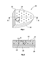
Figur 1 eine perspektivische Ansicht eines oralen Markerträgers, -
Figur 2 einen Längsschnitt durch den Markerträger derFigur 1 , -
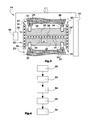
Figur 3 einen Querschnitt durch einen Patientenkiefer mit eingesetztem intraoralen Markerträger und einem digitalen Volumentomographie-Gerät, und -
Figur 4 ein Ablaufdiagramm eines Verfahrens zur Generierung einer radiologischen dreidimensionalen Aufnahme eines Patientenkopfes. - Die in den Figuren dargestellten Ausführungsbeispiele beziehen sich auf eine zahnärztliche Anwendung, wobei der Körperteil vorliegend ein Patientenkiefer ist.
- In den
Figuren 1 und 2 ist schematisch ein intraoraler Markerträger 10 dargestellt, wie er zur Generierung einer radiologischen dreidimensionalen Aufnahme mit einem digitalen Volumentomographie-Gerät geeignet ist. Der Markerträger 10 besteht aus einem radiologisch nicht sichtbaren Trägerkörper 12 aus einem geeigneten Kunststoff. An dem Trägerkörper 12 ist ein Individualformteil 16 angebracht, beispielsweise verklebt, das Zahnausnehmungen 18 aufweist, die komplementär zu den Patientenzähnen 24 geformt sind. Mit dem Individualformteil 16, das eine Abformung des betreffenden Patientenkiefers 22,23 darstellt, wird ein fester, unverrückbarer und definierter Sitz des Markerträger 10 auf dem Patientenkiefer 22,23 in dem Patientenmund sichergestellt. - In den Trägerkörper 12 sind radiologisch sichtbare, also radioopake, Markerelemente 14 in zwei Ebenen liegend und gleichmäßig verteilt angeordnet. Drei zueinander benachbarte Markerelemente 14 bilden jeweils ein gleichseitiges Dreieck, und sind jeweils mit einem für alle Markerelemente 14 gleichen Ist-Abstand D zueinander beabstandet, der nicht größer als 3,0 cm ist. Alle Markerelemente 14 haben eine identische Größe S, die beispielsweise bei kugelförmigen Markerelementen 14 dem Durchmesser entspricht. Die Größe S beträgt maximal wenige Millimeter. In der
Figur 2 ist ein zweites Ausführungsbeispiel eines komplexeren Markerträgers 20 dargestellt, der in den Patientenmund eingesetzt ist. Ferner ist ein um eine Vertikalachse rotierender Rotor 44 eines digitalen Volumentomographie-Gerätes dargestellt, der eine Röntgenstrahlungsquelle 40, die einen konusförmigen Röntgenstrahl generiert, und gegenüberliegend einen zweidimensionalen Detektor 42 trägt. - Der Markerträger 20 ist im Querschnitt H-förmig ausgebildet und weist einen horizontalen Trägerkörper-Teil 26 und an seinem Außenumfang jeweils nach oben und unten abragende vertikale Tragerkörper-Teile 30,32 auf. In den Grundebenen der Trägerkörper-Teile 26,30,32 sind jeweils die Markerelemente 14 flächig verteilt angeordnet. Auf der Oberseite und der Unterseite des horizontalen Trägerkörper-Teils ist jeweils ein Individualformteil 28,29 fixiert, das von dem Oberkiefer 22 bzw. dem Unterkiefer 23 abgeformt ist. Die Anordnung der Markerelemente 14 entspricht prinzipiell der in dem Markerträger 10 der
Figuren 1 und 2 . - Die meisten Markerträger 14 in dem horizontalen Trägerkörper-Teil 26 sind innerhalb der von den Patienten-Zähnen 24 des Patienten-Oberkiefers 22 und -Unterkiefers 23 aufgespannten Zahnbögen 36,37 angeordnet. Insbesondere die Markerelemente 14' in den vertikalen Trägerkörper-Teilen 30,32 sind außerhalb der Zahnbögen 36,37, jedoch innerhalb des Patientenmundes angeordnet.
- Das Verfahren zur Generierung einer radiologischen dreidimensionalen Aufnahme des Patientenkiefers läuft wie folgt ab:
- Zunächst wird in einem ersten Verfahrensschritt 50 der Markerträger 20 in den Patientenmund eingesetzt. Die Fixierung des Markerträger 20 in Patientenmund erfolgt durch den Aufbiss des Patienten.
- Anschließend wird in den nächsten Verfahrensschritt 52 mit dem digitalen Volumentomographie-Gerät eine Aufnahme des Patientenkiefers zur Erzeugung eines dreidimensionalen Rohbildes des Patientenkopfes bzw. - kiefers gemacht. Daraufhin wird in einem weiteren Verfahrensschritt 54 in dem Rohbild bezüglich aller Markerelemente ihrer Größe S' und die Abstände D' der Markerelemente zueinander vermessen.
- Daraufhin werden in dem folgenden Verfahrensschritt 56 die vermessenen Werte für die Markerelement-Abstände D' mit dem bekannten Ist-Wert D abgeglichen, bzw. hieraus ein Quotient generiert. Aus den lokalen Quotienten der Rohbild-Abstände D' und der konstanten Ist-Abstände D der Markerelemente zueinander wird unmittelbar ein Korrekturwert QD generiert, um den das Rohbild in einem anschließenden Verfahrensschritt 58 lokal zu korrigieren. Die Korrektur ist jeweils eine Größenkorrektur des Rohbildes anhand der Rohbild-Abstände D' im Verhältnis zu den Ist-Abeständen D der Markerelemente zueinander.
- Das auf diese Weise gewonnene dreidimensionale korrigierte Bild des Patientenkopfes bzw. des Patientenkiefers ist insbesondere bezüglich der Größenverhältnisse und Abstände erheblich genauer als das Rohbild. Insbesondere für die Planung von dentalen Implantaten wird auf diese Weise eine exakte dreidimensionale Abbildung des Patientenkiefers zur Verfügung gestellt, die die Basis für die anschließende genaue Planung und Realisierung der implantologischen dentalen Versorgung darstellt.
- Ergänzend hierzu werden mehrere lokale Qualitätsindikatoren QS ausgegeben bzw. in das korrigierte Rohbild eingeblendet, deren Wert sich aus der relativen Abweichung der Rohbild-Größe S' zu der Ist-Größe S der Markerelemente ergibt. Der Größen-Qualitätsindikator QS gibt Auskunft darüber, von welcher Qualität das Rohbild an dem betreffenden Ort ist, und gibt insbesondere Auskunft darüber, inwieweit dem Rohbild bzw. dem korrigierten Rohbild vertraut werden kann.
- Die Radioopazität der Markerelemente 14,14' ist verschieden. Bezogen auf das Ausführungsbeispiel der
Fig. 3 kann an dem vertikalen Trägerkörper-Teil 30 an vier Positionen des Zahnbogens ein Spektrum von drei bis sechs vertikal zueinander benachbarten Markerelementen 14' verschiedener Radioopazität vorgesehen sein. Diese werden in dem Rohbild dazu genutzt, das Rohbild bezüglich seiner Helligkeit und seines Kontrastes jeweils lokal zu kalibrieren. Diese Kalibrierung kann in den vier Bereichen durchaus verschieden ausfallen. Das hierbei gewonnene Bild erleichtert erheblich die Unterscheidung von Knochen und Gewebe.
Claims (10)
- Verfahren zur Generierung einer radiologischen dreidimensionalen digitalen Volumentomographie-Aufnahme eines Patienten-Körperteils, insbesondere eines Patientenkopfes, mit den Verfahrensschritten:Fixieren eines Markerträgers (10; 20) an dem Körperteil, bevorzugt in den Patientenmund, wobei der Markerträger (10; 20) einen nicht-radioopaken Trägerkörper (12; 26) aufweist, an dem mehrere radioopake Markerelemente (14,14') fixiert sind, deren Ist-Größe S und/oder Ist-Abstand D zueinander bekannt ist,Aufnahme des Körperteils mit einem digitalen Volumentomographie-Gerät zu Erzeugung eines dreidimensionalen Rohbildes des Körperteils,Vermessen der Größe S' und/oder des Abstandes D' der Markerelemente (14) zueinander in dem Rohbild,Erzeugung von Abweichungswerten QS, QD aus einem Abgleich der Rohbild-Größe S' und/oder der Rohblid-Abstände D' mit den jeweiligen Ist-Werten S, D, undKorrektur des Rohbildes anhand der Abgleichungswerte QS,QD.
- Verfahren zur Generierung einer dreidimensionalen Aufnahme eines Körperteils nach Anspruch 1, wobei die Korrektur eine Größenkorrektur des Rohbildes anhand der Rohbild-Abstände D' im Verhältnis zu den Ist-Abständen D der Markerelemente (14,14') ist.
- Verfahren zur Generierung einer dreidimensionalen Aufnahme eines Körperteils nach einem der vorangegangenen Ansprüche, wobei ein Qualitätsindikator ausgegeben wird, dessen Wert sich aus der Abweichung der Rohbild-Größe S' zu der Ist-Größe S der Markerelemente (14,14') ergibt.
- Verfahren zur Generierung einer dreidimensionalen Aufnahme eines Körperteils nach einem der vorangegangenen Ansprüche, wobei mindestens zehn Markerelemente (14,14') vorgesehen sind, wobei jedes Markerelement (14,14') zu seinen Nachbar-Markerelementen (14,14') jeweils in einem konstanten Ist-Abstand von höchstens 3,0 cm angeordnet ist, und wobei die Größenkorrektor mehrfach lokal anhand der lokalen Vergleichswerte vorgenommen wird.
- Verfahren zur Generierung einer dreidimensionalen Aufnahme eines Körperteils nach einem der vorangegangenen Ansprüche, wobei drei zueinander benachbarte Markerelemente (14,14') jeweils ein gleichseitiges Dreieck bilden.
- Verfahren zur Generierung einer dreidimensionalen Aufnahme eines Körperteils nach einem der vorangegangenen Ansprüche, wobei die Markerelemente (14) in mindestens zwei Querebenen angeordnet sind.
- Verfahren zur Generierung einer dreidimensionalen Aufnahme eines Körperteils nach einem der vorangegangenen Ansprüche, wobei die Radioopazität der Markerelemente (14,14') verschieden ist, mit dem Verfahrensschritt:Kalibrierung der Helligkeit des Rohbildes auf Grundlage der bekannten verschiedenen Radioopazitäts-Werte der Markerelemente (14,14').
- Verfahren zur Generierung einer dreidimensionalen Aufnahme eines Körperteils nach einem der vorangegangenen Ansprüche , wobei der Körperteil der Patientenkiefer (22,23) ist, und mehrere Markerelemente (14) innerhalb des Zahnbogens (36,37) angeordnet sind.
- Verfahren zur Generierung einer dreidimensionalen Aufnahme eines Körperteils, wobei mindestens ein Markerelement (14') außerhalb des Zahnbogens (36,37) angeordnet ist.
- Verfahren zur Generierung einer dreidimensionalen Aufnahme eines Körperteils nach Anspruch 8 oder 9, wobei mindestens ein Markerelement außerhalb des Patientenmundes angeordnet ist.
Priority Applications (2)
| Application Number | Priority Date | Filing Date | Title |
|---|---|---|---|
| EP11162043.1A EP2510878B1 (de) | 2011-04-12 | 2011-04-12 | Verfahren zur Generierung einer radiologischen dreidimensionalen digitalen Volumentomographie-Aufnahme eines Patienten-Körperteils |
| US13/432,355 US8831322B2 (en) | 2011-04-12 | 2012-03-28 | Method of generating a three-dimensional digital radiological volume topography recording of a patient's body part |
Applications Claiming Priority (1)
| Application Number | Priority Date | Filing Date | Title |
|---|---|---|---|
| EP11162043.1A EP2510878B1 (de) | 2011-04-12 | 2011-04-12 | Verfahren zur Generierung einer radiologischen dreidimensionalen digitalen Volumentomographie-Aufnahme eines Patienten-Körperteils |
Publications (2)
| Publication Number | Publication Date |
|---|---|
| EP2510878A1 true EP2510878A1 (de) | 2012-10-17 |
| EP2510878B1 EP2510878B1 (de) | 2014-02-26 |
Family
ID=44454675
Family Applications (1)
| Application Number | Title | Priority Date | Filing Date |
|---|---|---|---|
| EP11162043.1A Active EP2510878B1 (de) | 2011-04-12 | 2011-04-12 | Verfahren zur Generierung einer radiologischen dreidimensionalen digitalen Volumentomographie-Aufnahme eines Patienten-Körperteils |
Country Status (2)
| Country | Link |
|---|---|
| US (1) | US8831322B2 (de) |
| EP (1) | EP2510878B1 (de) |
Families Citing this family (14)
| Publication number | Priority date | Publication date | Assignee | Title |
|---|---|---|---|---|
| US10595970B2 (en) | 2012-01-10 | 2020-03-24 | Esthetic Implant Solutions, Llc | Bonding of soft gingival tissues with anatomical and other dental prostheses |
| US9895209B2 (en) | 2012-01-10 | 2018-02-20 | Mark H. Blaisdell | Casting jig including elongate handle for chair-side manufacture of customizable sculptable anatomical healing caps, and method for forming bis-acrylic crown |
| US10507081B2 (en) | 2012-01-10 | 2019-12-17 | Esthetic Implant Solutions, Llc | Methods for taking an impression or scanning without requiring removal of a temporary healing abutment |
| US10709525B2 (en) | 2012-01-10 | 2020-07-14 | Esthetic Implant Solutions, Llc | Methods for taking an oral scan without requiring removal of a temporary healing abutment |
| US11253345B2 (en) | 2012-01-10 | 2022-02-22 | Esthetic Implant Solutions, Llc | Methods for integrating scans including 3D cone beam scan for positioning of implant and fabrication of dental prosthesis |
| US12491053B2 (en) | 2012-01-10 | 2025-12-09 | Esthetic Implant Solutions, Llc | Methods for integrating scans including 3D cone beam scan for positioning of implant and fabrication of dental prosthesis |
| US10568720B2 (en) | 2012-01-10 | 2020-02-25 | Estetic Implant Solutions, LLC | Dental implants with markers for determining three-dimensional positioning |
| US10016260B2 (en) | 2012-01-10 | 2018-07-10 | Mark H. Blaisdell | Anatomical healing abutments, kits, and methods |
| US20170165042A1 (en) * | 2015-12-11 | 2017-06-15 | Timothy Hillukka | Determining jaw and facial movement |
| WO2017169139A1 (ja) * | 2016-03-29 | 2017-10-05 | ソニー株式会社 | 画像処理装置、画像処理方法及び医療システム |
| US11559379B2 (en) | 2018-04-12 | 2023-01-24 | Esthetic Implant Solutions, Llc | Dental implants with markers for determining three-dimensional positioning |
| EP3937784B1 (de) * | 2019-03-12 | 2025-07-23 | Carestream Dental LLC | Bewegliche und statische kollimatoren und röntgenquellenanordnungen zur intraoralen tomosynthese |
| ES2807700A1 (es) * | 2019-08-23 | 2021-02-23 | Accurate Fit Sl | Sistema, método y programas de ordenador para ubicación de implantes dentales |
| TWI877333B (zh) * | 2020-03-30 | 2025-03-21 | 美商尼奧西斯股份有限公司 | 引導式手術機器人夾板裝置 |
Citations (11)
| Publication number | Priority date | Publication date | Assignee | Title |
|---|---|---|---|---|
| WO1999044503A1 (en) * | 1998-03-05 | 1999-09-10 | Wake Forest University | Method and system for creating three-dimensional images using tomosynthetic computed tomography |
| WO2001033511A2 (en) * | 1999-11-03 | 2001-05-10 | Case Western Reserve University | System and method for producing a three-dimensional model |
| WO2002032307A1 (en) * | 2000-10-18 | 2002-04-25 | Paieon Inc. | Method and system for measuring dimensions of an organ |
| US20030086535A1 (en) * | 2001-11-08 | 2003-05-08 | Pierre Teppaz | Multimodality imaging phantom and process for manufacturing said phantom |
| WO2004100767A2 (en) * | 2003-05-09 | 2004-11-25 | Vanderbilt University | Fiducial marker holder system for surgery |
| WO2006094156A2 (en) * | 2005-03-02 | 2006-09-08 | Calypso Medical Technologies, Inc. | Systems and methods for treating a patient using guided radiation therapy or surgery |
| US20070122020A1 (en) * | 2005-11-29 | 2007-05-31 | General Electric Company | Method and device for geometry analysis and calibration of volumetric imaging systems |
| GB2449113A (en) * | 2007-05-11 | 2008-11-12 | Cameron Nigel Glenvi Carpenter | Apparatus For Measurement Accuracy Testing Of Radiological Imaging Modalities And Networked Digital Viewing Platforms |
| US20090018437A1 (en) * | 2007-07-12 | 2009-01-15 | Cooke T Derek | Radiographic imaging method and apparatus |
| US20090086887A1 (en) * | 2007-09-28 | 2009-04-02 | Fujifilm Corp | Radiation image capturing apparatus |
| US20100278311A1 (en) * | 2008-10-28 | 2010-11-04 | Kevin Hammerstrom | Device and method for scaling medical images |
Family Cites Families (23)
| Publication number | Priority date | Publication date | Assignee | Title |
|---|---|---|---|---|
| WO1995020343A1 (en) * | 1994-01-28 | 1995-08-03 | Schneider Medical Technologies, Inc. | Imaging device and method |
| US6259943B1 (en) * | 1995-02-16 | 2001-07-10 | Sherwood Services Ag | Frameless to frame-based registration system |
| DE59710242D1 (de) * | 1996-03-06 | 2003-07-10 | Hahn Rainer | Vorrichtung zum Herstellen von Zahnabdrücken |
| US6640127B1 (en) * | 1999-06-10 | 2003-10-28 | Olympus Optical Co., Ltd. | Surgical operation navigating system using a reference frame |
| KR100608997B1 (ko) * | 2002-08-26 | 2006-08-09 | 한국과학기술연구원 | 턱 운동 측정장치 및 측정방법 |
| US20040121282A1 (en) * | 2002-10-09 | 2004-06-24 | Sildve Peter O. | Apparatus and method for positioning dental arch to dental articulator |
| US20060281991A1 (en) * | 2003-05-09 | 2006-12-14 | Fitzpatrick J M | Fiducial marker holder system for surgery |
| WO2005088520A1 (en) * | 2004-03-11 | 2005-09-22 | University Of Cincinnati | Automated spine survey iterative scan technique (assist) |
| WO2005091978A2 (en) * | 2004-03-22 | 2005-10-06 | Vanderbilt University | System and methods for surgical instrument disablement via image-guided position feedback |
| CA2580374C (en) * | 2004-09-14 | 2014-11-18 | Oratio B.V. | Method of manufacturing and installing a ceramic dental implant with an aesthetic implant abutment |
| WO2006111964A2 (en) * | 2005-04-18 | 2006-10-26 | Denx, Advanced Medical Systems Ltd. | Methods and apparatus for dental implantation |
| US8215957B2 (en) * | 2005-05-12 | 2012-07-10 | Robert Shelton | Dental implant placement locator and method of use |
| US20070141525A1 (en) * | 2005-12-16 | 2007-06-21 | Cinader Jr David K | Registering banded appliances for digital orthodontics treatment planning |
| JP4670658B2 (ja) * | 2006-01-25 | 2011-04-13 | 富士ゼロックス株式会社 | 画像処理装置、画像処理方法及びプログラム |
| DE102006004197A1 (de) * | 2006-01-26 | 2007-08-09 | Klett, Rolf, Dr.Dr. | Verfahren und Vorrichtung zur Aufzeichnung von Körperbewegungen |
| WO2008051129A1 (en) * | 2006-10-27 | 2008-05-02 | Nobel Biocare Services Ag | A dental impression tray for use in obtaining an impression of a dental structure |
| US20080286715A1 (en) * | 2007-05-16 | 2008-11-20 | Woncheol Choi | System and method for providing an image guided implant surgical guide |
| JP5250251B2 (ja) * | 2007-12-17 | 2013-07-31 | イマグノーシス株式会社 | 医用撮影用マーカーおよびその活用プログラム |
| EP2119397B1 (de) * | 2008-05-15 | 2013-12-18 | Brainlab AG | Bestimmung einer Kalibrier-Information für ein Röntgengerät |
| JP2010025759A (ja) * | 2008-07-18 | 2010-02-04 | Fuji Xerox Co Ltd | 位置計測システム |
| EP2391297A1 (de) * | 2009-01-30 | 2011-12-07 | Ady Palti | Okklusionsschablone |
| US8363919B2 (en) * | 2009-11-25 | 2013-01-29 | Imaging Sciences International Llc | Marker identification and processing in x-ray images |
| US20110230755A1 (en) * | 2010-03-04 | 2011-09-22 | Macfarlane Duncan | Single camera motion measurement and monitoring for magnetic resonance applications |
-
2011
- 2011-04-12 EP EP11162043.1A patent/EP2510878B1/de active Active
-
2012
- 2012-03-28 US US13/432,355 patent/US8831322B2/en active Active
Patent Citations (11)
| Publication number | Priority date | Publication date | Assignee | Title |
|---|---|---|---|---|
| WO1999044503A1 (en) * | 1998-03-05 | 1999-09-10 | Wake Forest University | Method and system for creating three-dimensional images using tomosynthetic computed tomography |
| WO2001033511A2 (en) * | 1999-11-03 | 2001-05-10 | Case Western Reserve University | System and method for producing a three-dimensional model |
| WO2002032307A1 (en) * | 2000-10-18 | 2002-04-25 | Paieon Inc. | Method and system for measuring dimensions of an organ |
| US20030086535A1 (en) * | 2001-11-08 | 2003-05-08 | Pierre Teppaz | Multimodality imaging phantom and process for manufacturing said phantom |
| WO2004100767A2 (en) * | 2003-05-09 | 2004-11-25 | Vanderbilt University | Fiducial marker holder system for surgery |
| WO2006094156A2 (en) * | 2005-03-02 | 2006-09-08 | Calypso Medical Technologies, Inc. | Systems and methods for treating a patient using guided radiation therapy or surgery |
| US20070122020A1 (en) * | 2005-11-29 | 2007-05-31 | General Electric Company | Method and device for geometry analysis and calibration of volumetric imaging systems |
| GB2449113A (en) * | 2007-05-11 | 2008-11-12 | Cameron Nigel Glenvi Carpenter | Apparatus For Measurement Accuracy Testing Of Radiological Imaging Modalities And Networked Digital Viewing Platforms |
| US20090018437A1 (en) * | 2007-07-12 | 2009-01-15 | Cooke T Derek | Radiographic imaging method and apparatus |
| US20090086887A1 (en) * | 2007-09-28 | 2009-04-02 | Fujifilm Corp | Radiation image capturing apparatus |
| US20100278311A1 (en) * | 2008-10-28 | 2010-11-04 | Kevin Hammerstrom | Device and method for scaling medical images |
Also Published As
| Publication number | Publication date |
|---|---|
| US8831322B2 (en) | 2014-09-09 |
| EP2510878B1 (de) | 2014-02-26 |
| US20120263363A1 (en) | 2012-10-18 |
Similar Documents
| Publication | Publication Date | Title |
|---|---|---|
| EP2510878B1 (de) | Verfahren zur Generierung einer radiologischen dreidimensionalen digitalen Volumentomographie-Aufnahme eines Patienten-Körperteils | |
| DE102007008118B4 (de) | Verfahren zur Erzeugung tomographischer Darstellungen mit einem Röntgen-Computertomographie-System mit Streustrahlungskorrektur | |
| DE10206716B4 (de) | Verfahren zur Festlegung eines Zielbereichs einer CT-Röntgenbildaufnahmevorrichtung | |
| DE60018394T2 (de) | Megavolt-computertomographie während der strahlentherapie | |
| EP3389496B1 (de) | Verfahren zur kalibrierung einer röntgenaufnahme | |
| DE102009039486B4 (de) | Röntgen-CT-Abbildungsvorrichtung und Abbildungssteuerverfahren dafür | |
| DE102015222821B4 (de) | Verfahren und Vorrichtung zum Betreiben eines dentaldiagnostischen Bilderzeugungssystems | |
| DE112017002369T5 (de) | Stationäre intraorale Tomosynthesebildgebungssysteme und-Verfahren sowie computerlesbare Medien für die dreidimensionale Dentalbildgebung | |
| WO2015128108A1 (de) | Einstellen einer röntgenstrahlungseinheit | |
| DE102012217569B4 (de) | Automatische Festlegung einer spektralen Verteilung von Röntgenstrahlung einer Anzahl von Röntgenquellen | |
| DE102011055616A1 (de) | System und Verfahren zur Brustbildgebung mittels Röntgen-Computertomographie | |
| DE102007026801A1 (de) | Röntgen-CT-Gerät | |
| DE102008010537A1 (de) | Röntgen-CT-Anzeigeverfahren für den Kieferbereich; CT-Röntgenvorrichtung und Röntgenbild-Anzeigevorrichtung | |
| WO2012097801A1 (de) | Verfahren zur erzeugung einer kontrastmittelunterstützten röntgendarstellung und ein röntgensystem | |
| DE102009057066A1 (de) | Bildgebungsvorrichtung, Strahlentherapiegerät mit einer derartigen Bildgebungsvorrichtung, Verfahren zur Erzeugung eines Bildes und Computerprogrammprodukt | |
| EP1764040A2 (de) | Verfahren zur artefaktreduzierten radiologischen 3D-Bildgebung, Medizinische Bildgebungsvorrichtung und Verfahren zur Erstellung eines Therapieplans | |
| DE102007014829B3 (de) | Verfahren zur Streustrahlungskorrektur in bildgebenden Röntgengeräten sowie Röntgenbildgebungssystem | |
| DE102012212774A1 (de) | Verfahren zur Korrektur von Metallartefakten und Röntgeneinrichtung | |
| DE102006045769A1 (de) | Röntgen-CT-Vorrichtung | |
| DE10224315A1 (de) | Verfahren zum Bestimmung von Korrektur-Koeffizienten für Detektorkanäle eines Computertomographen | |
| EP1922013A1 (de) | Verfahren zur herstellung eines führungsorgans zum führen eines chirurgischen instrumentes sowie nach diesem verfahren hergestelltes führungsorgan | |
| DE102004033989B4 (de) | Verfahren zur Messung der dreidimensionalen Dichteverteilung in Knochen | |
| EP3552547A1 (de) | Verfahren zur bereitstellung einer konvertierungsinformation zu einem bilddatensatz, röntgeneinrichtung, computerprogramm und elektronisch lesbarer datenträger | |
| DE102022203101B3 (de) | Verfahren zur Artefaktkorrektur in einem Computertomographiebilddatensatz, Computertomographieeinrichtung, Computerprogramm und elektronisch lesbarer Datenträger | |
| DE202020104200U1 (de) | Gerät zur Aufnahme von Panoramaschicht-Röntgenbildern, CBCT-Volumen-Röntgenbildern und Fernröntgenbildern |
Legal Events
| Date | Code | Title | Description |
|---|---|---|---|
| PUAI | Public reference made under article 153(3) epc to a published international application that has entered the european phase |
Free format text: ORIGINAL CODE: 0009012 |
|
| AK | Designated contracting states |
Kind code of ref document: A1 Designated state(s): AL AT BE BG CH CY CZ DE DK EE ES FI FR GB GR HR HU IE IS IT LI LT LU LV MC MK MT NL NO PL PT RO RS SE SI SK SM TR |
|
| AX | Request for extension of the european patent |
Extension state: BA ME |
|
| 17P | Request for examination filed |
Effective date: 20130328 |
|
| GRAP | Despatch of communication of intention to grant a patent |
Free format text: ORIGINAL CODE: EPIDOSNIGR1 |
|
| RIC1 | Information provided on ipc code assigned before grant |
Ipc: G06T 11/00 20060101ALI20130809BHEP Ipc: A61B 6/00 20060101AFI20130809BHEP Ipc: A61B 6/14 20060101ALI20130809BHEP Ipc: A61B 6/12 20060101ALI20130809BHEP Ipc: G06T 3/40 20060101ALI20130809BHEP |
|
| INTG | Intention to grant announced |
Effective date: 20130910 |
|
| GRAS | Grant fee paid |
Free format text: ORIGINAL CODE: EPIDOSNIGR3 |
|
| GRAA | (expected) grant |
Free format text: ORIGINAL CODE: 0009210 |
|
| AK | Designated contracting states |
Kind code of ref document: B1 Designated state(s): AL AT BE BG CH CY CZ DE DK EE ES FI FR GB GR HR HU IE IS IT LI LT LU LV MC MK MT NL NO PL PT RO RS SE SI SK SM TR |
|
| REG | Reference to a national code |
Ref country code: GB Ref legal event code: FG4D Free format text: NOT ENGLISH |
|
| REG | Reference to a national code |
Ref country code: CH Ref legal event code: EP |
|
| REG | Reference to a national code |
Ref country code: AT Ref legal event code: REF Ref document number: 653082 Country of ref document: AT Kind code of ref document: T Effective date: 20140315 |
|
| REG | Reference to a national code |
Ref country code: IE Ref legal event code: FG4D Free format text: LANGUAGE OF EP DOCUMENT: GERMAN |
|
| REG | Reference to a national code |
Ref country code: DE Ref legal event code: R096 Ref document number: 502011002199 Country of ref document: DE Effective date: 20140410 |
|
| REG | Reference to a national code |
Ref country code: NL Ref legal event code: VDEP Effective date: 20140226 |
|
| REG | Reference to a national code |
Ref country code: LT Ref legal event code: MG4D |
|
| PG25 | Lapsed in a contracting state [announced via postgrant information from national office to epo] |
Ref country code: IS Free format text: LAPSE BECAUSE OF FAILURE TO SUBMIT A TRANSLATION OF THE DESCRIPTION OR TO PAY THE FEE WITHIN THE PRESCRIBED TIME-LIMIT Effective date: 20140626 Ref country code: LT Free format text: LAPSE BECAUSE OF FAILURE TO SUBMIT A TRANSLATION OF THE DESCRIPTION OR TO PAY THE FEE WITHIN THE PRESCRIBED TIME-LIMIT Effective date: 20140226 Ref country code: NO Free format text: LAPSE BECAUSE OF FAILURE TO SUBMIT A TRANSLATION OF THE DESCRIPTION OR TO PAY THE FEE WITHIN THE PRESCRIBED TIME-LIMIT Effective date: 20140526 |
|
| PG25 | Lapsed in a contracting state [announced via postgrant information from national office to epo] |
Ref country code: PT Free format text: LAPSE BECAUSE OF FAILURE TO SUBMIT A TRANSLATION OF THE DESCRIPTION OR TO PAY THE FEE WITHIN THE PRESCRIBED TIME-LIMIT Effective date: 20140626 Ref country code: CY Free format text: LAPSE BECAUSE OF FAILURE TO SUBMIT A TRANSLATION OF THE DESCRIPTION OR TO PAY THE FEE WITHIN THE PRESCRIBED TIME-LIMIT Effective date: 20140226 Ref country code: SE Free format text: LAPSE BECAUSE OF FAILURE TO SUBMIT A TRANSLATION OF THE DESCRIPTION OR TO PAY THE FEE WITHIN THE PRESCRIBED TIME-LIMIT Effective date: 20140226 Ref country code: FI Free format text: LAPSE BECAUSE OF FAILURE TO SUBMIT A TRANSLATION OF THE DESCRIPTION OR TO PAY THE FEE WITHIN THE PRESCRIBED TIME-LIMIT Effective date: 20140226 Ref country code: NL Free format text: LAPSE BECAUSE OF FAILURE TO SUBMIT A TRANSLATION OF THE DESCRIPTION OR TO PAY THE FEE WITHIN THE PRESCRIBED TIME-LIMIT Effective date: 20140226 |
|
| PG25 | Lapsed in a contracting state [announced via postgrant information from national office to epo] |
Ref country code: HR Free format text: LAPSE BECAUSE OF FAILURE TO SUBMIT A TRANSLATION OF THE DESCRIPTION OR TO PAY THE FEE WITHIN THE PRESCRIBED TIME-LIMIT Effective date: 20140226 Ref country code: LV Free format text: LAPSE BECAUSE OF FAILURE TO SUBMIT A TRANSLATION OF THE DESCRIPTION OR TO PAY THE FEE WITHIN THE PRESCRIBED TIME-LIMIT Effective date: 20140226 |
|
| PG25 | Lapsed in a contracting state [announced via postgrant information from national office to epo] |
Ref country code: CZ Free format text: LAPSE BECAUSE OF FAILURE TO SUBMIT A TRANSLATION OF THE DESCRIPTION OR TO PAY THE FEE WITHIN THE PRESCRIBED TIME-LIMIT Effective date: 20140226 Ref country code: RO Free format text: LAPSE BECAUSE OF FAILURE TO SUBMIT A TRANSLATION OF THE DESCRIPTION OR TO PAY THE FEE WITHIN THE PRESCRIBED TIME-LIMIT Effective date: 20140226 Ref country code: DK Free format text: LAPSE BECAUSE OF FAILURE TO SUBMIT A TRANSLATION OF THE DESCRIPTION OR TO PAY THE FEE WITHIN THE PRESCRIBED TIME-LIMIT Effective date: 20140226 Ref country code: EE Free format text: LAPSE BECAUSE OF FAILURE TO SUBMIT A TRANSLATION OF THE DESCRIPTION OR TO PAY THE FEE WITHIN THE PRESCRIBED TIME-LIMIT Effective date: 20140226 |
|
| REG | Reference to a national code |
Ref country code: DE Ref legal event code: R097 Ref document number: 502011002199 Country of ref document: DE |
|
| PG25 | Lapsed in a contracting state [announced via postgrant information from national office to epo] |
Ref country code: ES Free format text: LAPSE BECAUSE OF FAILURE TO SUBMIT A TRANSLATION OF THE DESCRIPTION OR TO PAY THE FEE WITHIN THE PRESCRIBED TIME-LIMIT Effective date: 20140226 Ref country code: PL Free format text: LAPSE BECAUSE OF FAILURE TO SUBMIT A TRANSLATION OF THE DESCRIPTION OR TO PAY THE FEE WITHIN THE PRESCRIBED TIME-LIMIT Effective date: 20140226 Ref country code: SK Free format text: LAPSE BECAUSE OF FAILURE TO SUBMIT A TRANSLATION OF THE DESCRIPTION OR TO PAY THE FEE WITHIN THE PRESCRIBED TIME-LIMIT Effective date: 20140226 Ref country code: MC Free format text: LAPSE BECAUSE OF FAILURE TO SUBMIT A TRANSLATION OF THE DESCRIPTION OR TO PAY THE FEE WITHIN THE PRESCRIBED TIME-LIMIT Effective date: 20140226 Ref country code: LU Free format text: LAPSE BECAUSE OF FAILURE TO SUBMIT A TRANSLATION OF THE DESCRIPTION OR TO PAY THE FEE WITHIN THE PRESCRIBED TIME-LIMIT Effective date: 20140412 |
|
| REG | Reference to a national code |
Ref country code: CH Ref legal event code: PL |
|
| PLBE | No opposition filed within time limit |
Free format text: ORIGINAL CODE: 0009261 |
|
| STAA | Information on the status of an ep patent application or granted ep patent |
Free format text: STATUS: NO OPPOSITION FILED WITHIN TIME LIMIT |
|
| REG | Reference to a national code |
Ref country code: IE Ref legal event code: MM4A |
|
| PG25 | Lapsed in a contracting state [announced via postgrant information from national office to epo] |
Ref country code: LI Free format text: LAPSE BECAUSE OF NON-PAYMENT OF DUE FEES Effective date: 20140430 Ref country code: CH Free format text: LAPSE BECAUSE OF NON-PAYMENT OF DUE FEES Effective date: 20140430 |
|
| 26N | No opposition filed |
Effective date: 20141127 |
|
| REG | Reference to a national code |
Ref country code: DE Ref legal event code: R097 Ref document number: 502011002199 Country of ref document: DE Effective date: 20141127 |
|
| PG25 | Lapsed in a contracting state [announced via postgrant information from national office to epo] |
Ref country code: IT Free format text: LAPSE BECAUSE OF FAILURE TO SUBMIT A TRANSLATION OF THE DESCRIPTION OR TO PAY THE FEE WITHIN THE PRESCRIBED TIME-LIMIT Effective date: 20140226 |
|
| PG25 | Lapsed in a contracting state [announced via postgrant information from national office to epo] |
Ref country code: IE Free format text: LAPSE BECAUSE OF NON-PAYMENT OF DUE FEES Effective date: 20140412 |
|
| PG25 | Lapsed in a contracting state [announced via postgrant information from national office to epo] |
Ref country code: SI Free format text: LAPSE BECAUSE OF FAILURE TO SUBMIT A TRANSLATION OF THE DESCRIPTION OR TO PAY THE FEE WITHIN THE PRESCRIBED TIME-LIMIT Effective date: 20140226 |
|
| PG25 | Lapsed in a contracting state [announced via postgrant information from national office to epo] |
Ref country code: MT Free format text: LAPSE BECAUSE OF FAILURE TO SUBMIT A TRANSLATION OF THE DESCRIPTION OR TO PAY THE FEE WITHIN THE PRESCRIBED TIME-LIMIT Effective date: 20140226 |
|
| REG | Reference to a national code |
Ref country code: FR Ref legal event code: PLFP Year of fee payment: 6 |
|
| PG25 | Lapsed in a contracting state [announced via postgrant information from national office to epo] |
Ref country code: SM Free format text: LAPSE BECAUSE OF FAILURE TO SUBMIT A TRANSLATION OF THE DESCRIPTION OR TO PAY THE FEE WITHIN THE PRESCRIBED TIME-LIMIT Effective date: 20140226 |
|
| PG25 | Lapsed in a contracting state [announced via postgrant information from national office to epo] |
Ref country code: GR Free format text: LAPSE BECAUSE OF FAILURE TO SUBMIT A TRANSLATION OF THE DESCRIPTION OR TO PAY THE FEE WITHIN THE PRESCRIBED TIME-LIMIT Effective date: 20140527 Ref country code: BG Free format text: LAPSE BECAUSE OF FAILURE TO SUBMIT A TRANSLATION OF THE DESCRIPTION OR TO PAY THE FEE WITHIN THE PRESCRIBED TIME-LIMIT Effective date: 20140226 Ref country code: RS Free format text: LAPSE BECAUSE OF NON-PAYMENT OF DUE FEES Effective date: 20140226 |
|
| PG25 | Lapsed in a contracting state [announced via postgrant information from national office to epo] |
Ref country code: BE Free format text: LAPSE BECAUSE OF FAILURE TO SUBMIT A TRANSLATION OF THE DESCRIPTION OR TO PAY THE FEE WITHIN THE PRESCRIBED TIME-LIMIT Effective date: 20140430 Ref country code: TR Free format text: LAPSE BECAUSE OF FAILURE TO SUBMIT A TRANSLATION OF THE DESCRIPTION OR TO PAY THE FEE WITHIN THE PRESCRIBED TIME-LIMIT Effective date: 20140226 Ref country code: HU Free format text: LAPSE BECAUSE OF FAILURE TO SUBMIT A TRANSLATION OF THE DESCRIPTION OR TO PAY THE FEE WITHIN THE PRESCRIBED TIME-LIMIT; INVALID AB INITIO Effective date: 20110412 |
|
| REG | Reference to a national code |
Ref country code: FR Ref legal event code: PLFP Year of fee payment: 7 |
|
| REG | Reference to a national code |
Ref country code: AT Ref legal event code: MM01 Ref document number: 653082 Country of ref document: AT Kind code of ref document: T Effective date: 20160412 |
|
| PG25 | Lapsed in a contracting state [announced via postgrant information from national office to epo] |
Ref country code: AT Free format text: LAPSE BECAUSE OF NON-PAYMENT OF DUE FEES Effective date: 20160412 |
|
| REG | Reference to a national code |
Ref country code: FR Ref legal event code: PLFP Year of fee payment: 8 |
|
| PG25 | Lapsed in a contracting state [announced via postgrant information from national office to epo] |
Ref country code: MK Free format text: LAPSE BECAUSE OF FAILURE TO SUBMIT A TRANSLATION OF THE DESCRIPTION OR TO PAY THE FEE WITHIN THE PRESCRIBED TIME-LIMIT Effective date: 20140226 |
|
| PG25 | Lapsed in a contracting state [announced via postgrant information from national office to epo] |
Ref country code: AL Free format text: LAPSE BECAUSE OF FAILURE TO SUBMIT A TRANSLATION OF THE DESCRIPTION OR TO PAY THE FEE WITHIN THE PRESCRIBED TIME-LIMIT Effective date: 20140226 |
|
| REG | Reference to a national code |
Ref country code: DE Ref legal event code: R082 Ref document number: 502011002199 Country of ref document: DE Representative=s name: VOSSIUS & PARTNER PATENTANWAELTE RECHTSANWAELT, DE Ref country code: DE Ref legal event code: R082 Ref document number: 502011002199 Country of ref document: DE Representative=s name: DENNEMEYER & ASSOCIATES S.A., DE Ref country code: DE Ref legal event code: R082 Ref document number: 502011002199 Country of ref document: DE Representative=s name: TERPATENT PATENTANWAELTE TER SMITTEN EBERLEIN-, DE |
|
| REG | Reference to a national code |
Ref country code: DE Ref legal event code: R082 Ref document number: 502011002199 Country of ref document: DE Representative=s name: VOSSIUS & PARTNER PATENTANWAELTE RECHTSANWAELT, DE Ref country code: DE Ref legal event code: R082 Ref document number: 502011002199 Country of ref document: DE Representative=s name: DENNEMEYER & ASSOCIATES S.A., DE |
|
| REG | Reference to a national code |
Ref country code: DE Ref legal event code: R082 Ref document number: 502011002199 Country of ref document: DE Representative=s name: VOSSIUS & PARTNER PATENTANWAELTE RECHTSANWAELT, DE |
|
| PGFP | Annual fee paid to national office [announced via postgrant information from national office to epo] |
Ref country code: DE Payment date: 20250429 Year of fee payment: 15 |
|
| PGFP | Annual fee paid to national office [announced via postgrant information from national office to epo] |
Ref country code: GB Payment date: 20250428 Year of fee payment: 15 |
|
| PGFP | Annual fee paid to national office [announced via postgrant information from national office to epo] |
Ref country code: FR Payment date: 20250425 Year of fee payment: 15 |