EP2510768A1 - A planter row unit - Google Patents
A planter row unit Download PDFInfo
- Publication number
- EP2510768A1 EP2510768A1 EP12159957A EP12159957A EP2510768A1 EP 2510768 A1 EP2510768 A1 EP 2510768A1 EP 12159957 A EP12159957 A EP 12159957A EP 12159957 A EP12159957 A EP 12159957A EP 2510768 A1 EP2510768 A1 EP 2510768A1
- Authority
- EP
- European Patent Office
- Prior art keywords
- row unit
- downforce
- furrow
- soil
- ground contacting
- Prior art date
- Legal status (The legal status is an assumption and is not a legal conclusion. Google has not performed a legal analysis and makes no representation as to the accuracy of the status listed.)
- Granted
Links
Images


Classifications
-
- A—HUMAN NECESSITIES
- A01—AGRICULTURE; FORESTRY; ANIMAL HUSBANDRY; HUNTING; TRAPPING; FISHING
- A01C—PLANTING; SOWING; FERTILISING
- A01C7/00—Sowing
- A01C7/20—Parts of seeders for conducting and depositing seed
- A01C7/201—Mounting of the seeding tools
- A01C7/205—Mounting of the seeding tools comprising pressure regulation means
-
- A—HUMAN NECESSITIES
- A01—AGRICULTURE; FORESTRY; ANIMAL HUSBANDRY; HUNTING; TRAPPING; FISHING
- A01C—PLANTING; SOWING; FERTILISING
- A01C5/00—Making or covering furrows or holes for sowing, planting or manuring
- A01C5/06—Machines for making or covering drills or furrows for sowing or planting
- A01C5/066—Devices for covering drills or furrows
Definitions
- This disclosure relates to a row unit for a seeding machine comprising a row unit frame adapted to mounted to a machine frame a furrow opener and a furrow depth regulating member both mounted to the row unit frame; and a furrow closing arrangement movably mounted to the row unit frame.
- the proper downforce for the opener does not always provide the proper downforce on the closing wheels.
- An adjustable spring is typically provided between the closing wheels and the row unit frame. This can be set by the operator before, operation and if needed, the operator can stop planting and readjust the closing wheels downforce springs. However, operators seldom will take the time to adjust the closing wheel downforce springs during planting.
- an object of this invention is to provide a row unit which facilitates the adjustment of the closing wheel downforce during planting.
- a row unit of the above mentioned type is provided with a furrow closing arrangement having a ground contacting member, and a furrow closing downforce actuator operable to vary force applied to soil by the ground contacting member as the seeding machine moves through a field.
- a row unit having an downforce control system for the closing wheels.
- the closing wheel downforce control may be active, that is closed loop, or inactive, that is open loop.
- This control of the downforce pressure for the closing wheels can be separate from the row unit downforce control or can be related to the row unit downforce control by making the closing wheel downforce proportional to the row unit downforce.
- a closed loop control operator input to the control system is used to set a desired downforce for the closing wheels.
- the control system then operates the downforce actuator to produce the desired downforce.
- a monitor displays a load to the operator who then commands operation of the downforce actuator to change the downforce on the closing wheels as desired.
- FIG. 1 illustrates a single row unit 12 of a multi-row planter, with each row crop unit 12 being substantially identical and connected to a machine frame 14 shown as a tool bar. Only a single row crop unit 12 is shown and described below for sake of simplicity.
- Row crop unit 12 includes a multi-part row unit frame 16 which is attached to tool bar by parallel linkage 18.
- the tool bar is coupled to a traction unit (not shown), such as an agricultural tractor.
- traction unit such as an agricultural tractor.
- tool bar may be coupled to an agricultural tractor using a draw bar or 3-point hitch assembly.
- the tool bar may be coupled with transport wheel assemblies, marker arms, etc. which may be of conventional design and not shown for clarity.
- Frame 16 carries a double disc furrow opener 20 for forming a seed furrow 26 in soil 27.
- An optional coulter wheel 22 and row cleaner 23, particularly for use in no till situations, may be placed ahead of double disc furrow opener 20.
- a pair of furrow depth regulating members 25 in the form of gauge wheels 24 are respectively associated with the pair of discs of double disc furrow opener 20. More particularly, each gauge wheel 24 is positioned generally in line with and immediately adjacent to the outside of each respective disc of double disc furrow opener 20. The gauge wheels 24 may be vertically adjusted to change the depth of the furrow which is cut into the soil using double disc furrow opener 20.
- a seed meter 32 is also carried by frame 16. Seed meter receives seed from a seed hopper 28 carried above the seed meter on the frame 16. The seed meter drive is not shown. Seed meter 32 delivers seed sequentially to a seed tube 36 through which the seed falls by gravity to the furrow 26, or other delivery device.
- a furrow closing arrangement 40 follows behind the gauge wheels with a pair of closing wheels 42 positioned generally in line with double disc furrow opener 20. Closing wheels 42 are preferably biased in a downward direction and have a peripheral edge with a shape which may vary, depending upon the application. Closing wheels 42 push soil back into the furrow 26 upon the seeds deposited therein. Closing wheels 42 serve as a ground contacting member.
- the row unit 12 is equipped with a row unit downforce actuator 43 in the form of an adjustable pneumatic downforce cylinder 44.
- the row unit downforce actuator 43 acts between the machine frame 14 and the lower links of the linkage 18 to apply downforce on the row unit to ensure there is a desired force of the gauge wheels 24 acting on the soil. This ensures that the double disc furrow opener 20 is forming the furrow 26 to the desired depth.
- the amount of the downforce on the row unit, and thus the force of the soil on the gauge wheels 24, is measured by a load sensor in the pivot pin 46 in the gauge wheel depth adjustment link 48.
- a suitable load sensing pin is shown in W02008/086283 A2 . Load sensors can be placed in a variety of locations on the gauge wheel support arm 49 or adjustment link 48.
- a controller receives a signal from the load sensor in the pin 46 and controls the pressure in the cylinder 44 accordingly to achieve a desired downforce on the gauge wheels.
- Furrow closing arrangement 40 provides for controlled downforce on the closing wheels.
- the control can be dynamic, that is changing the downforce during operation of the machine, either automatically (closed loop) or manually (open loop).
- Furrow closing arrangement 40 includes a mounting frame 50 ( Figs. 2-4 ) attached to the row unit frame 16 at the rear thereof. Shelf 51 of the mounting frame 50 is used to attach the mounting frame to the row unit frame 16. While the mounting frame 50 is a separate piece, once attached to the frame 16, it functions as part of the row unit frame 16. The mounting frame 50 is a separate piece to enable other closing options to be installed in the row unit but could be integrated into the frame 16 if desired.
- a pivot arm 52 is rotatably coupled to the row unit frame, via the mounting frame 50.
- the closing wheels 42 are mounted to the pivot arm 52.
- the pivot arm 52 serves as a first link in a parallelogram linkage 54.
- Linkage 54 includes a second link 56 and a coupler 58 connected to the first link, i.e. pivot arm 52, and to the second link 56.
- a pneumatic cylinder 60 is connected between the mounting frame 50 and the coupler 58 and serves as a furrow closing downforce actuator 61. When pressure in the cylinder 60 is increased, the closing wheels 42 exert a greater force on the soil to close the furrow 26.
- a slide member 62 connects the coupler 58 to the pivot arm 52. This allows for a limited degree of lateral movement of the pivot arm 52 while the cylinder 60 and coupler 58 remain fixed laterally. The coupler 58 only moves in a vertical direction.
- Fig. 4 is a sectional view through the attachment of the pivot arm 52 to the mounting frame 50. The attachment of each leg 66 is symmetrical. Bolt 67 and nut 68 attach the leg to the mounting frame using a bushing 69. The leg 66 does not directly contact the mounting frame 50. Instead, the bushing 69 engages the mounting frame 50.
- the bushing surface 70 is curved and complementary to the curved surface 71 of the mounting frame.
- the bolt 67 extends through a fore and aft extending slot 72 in the mounting frame.
- the slot and the curved surfaces 70 and 71 allow the pivot arm 52 to be adjusted about a vertical axis to adjust the side-to-side location of the closing wheels 42 to ensure they are center over the furrow 26.
- the bushing 69 has a projection 73 that is seated into the slot 72 to orient the bushing properly for mating of the surfaces 70 and 71.
- the slide member 62 allows the pivot arm to be adjusted without affecting the location of the lower end of the cylinder 60.
- the bolt 64 that connects the slide member 62 to the pivot arm 52 can be a load sensing pin having a load sensor similar to the pin 46 mentioned above.
- the sensor measures the load acting on the soil from the closing wheels.
- the bolt 64 is only one position of many that may be suitable for a load sensor to measure the load on the closing wheels. Any of the pivot pins in the closing wheel arrangement may be used to measure the load. Alternatively, a load cell may be attached to or integrated into the pivot arm or other links in the closing wheel arrangement.
- a control system 74 is shown schematically in Fig. 5 .
- a controller 76 receives a load signal from a load sensor 78 such as the bolt 64.
- An input device 80 enables a machine operator to input a desired downforce into the controller.
- the controller in turn generates a signal for an air pressure source 82, causing the pressure to increase or decrease.
- the air pressure is then directed to the actuator, or pneumatic cylinder 60.
- the pressure source 82 could be a fixed, that is constant, pressure source and the controller connected to a regulating valve between the pressure source and the cylinder 60.
- controller being operably connected to an actuator to vary the load applied to the soil is meant to mean the controller is connected to a pressure source or pressure control valve for pressure operated actuators or to an electrical control for an electric actuator. Any connection that enables the controller to operate the actuator is intended to be included.
- FIG. 6 An open loop control system 90 is shown in Fig. 6 , where like components from control system 74 are given the same reference numeral.
- the controller is replace with a monitor 92.
- the monitor 92 receives the output signal from the load sensor 78 and displays the load to an operator.
- the operator uses the input device 80 to control the pressure to operate the furrow closing downforce actuator 60.
- the input device operates through the monitor 92.
- the operator input can be directly to the pressure source 82 or a pressure regulating valve, etc.
- the control system is capable of dynamic (closed loop control) or open loop control to vary the downforce on the closing wheels with varying field conditions as the seeding machine moves through a field.
- the control system can be used to initially set the air pressure in the cylinder and then not change the pressure during operation.
- the load sensor 78 is not needed.
- Such a system would provide an advantage over a mechanical closing downforce system in that a single input to the controller or manual valve adjustment can adjust the closing wheel downforce on all or multiple row units without the need to manually adjust springs on each row unit individually.
- One load sensor 78, on one row unit 12 can be used as the feedback input to control the pressure in the cylinders 60 of multiple row units on the seeding machine. In other words, a load sensor is not needed for every row unit 12. Perhaps one load sensor for each section of the seeding machine frame is sufficient.
- Control system 86 uses one load sensor for measuring the downforce on the row unit.
- the load measured by the one sensor 78 is used in the control of both the row unit downforce and the closing wheel downforce.
- two or more load sensors can may be used in control system 86, one measuring the load on the furrow depth regulating member and another measuring the load on the closing wheel.
- Control system 86 has valve 88 connected to the pressure source 82 and supplies pressure to both the cylinder 60 for the closing wheel downforce actuator and the cylinder 44 for the row unit downforce.
- Valve 82 controls the pressure independently to the two actuators 44, 60, that is each actuator can be supplied with a different pressure.
- Valve 88 could be two separate valves if desired. Having two separate actuators for the row unit downforce and the furrow closing wheel downforce with independent control of the pressure to the two actuators, allows maximum flexibility to the operator in the control of row unit and closing downforce.
- a pressure regulator could be used to link and/or adjust forces between the two systems in an open-loop or closed-loop manner. Multiple cylinders 60 and 44 from multiple row units can be controlled with one controller 76 or manual adjustment.
- the closing wheel downforce arrangement includes an actuator operable to vary the downforce on the closing wheels as the machine moves through a field and an operator accessible switch or control to activate the actuator to vary the downforce.
- a load sensor and a monitor for the operator to see the measured load are optional.
- closing wheel downforce arrangement is disclosed and described in the context of a pneumatic cylinder used as the actuator, other actuators can be used such as a hydraulic, electronic or electro-mechanical, etc.
- the type of actuator is not critical. By providing control of the closing wheel downforce, the machine operator is better able to assure the seed furrow is properly closed.
- a pressure based actuator, pneumatic or hydraulic allows for more constant downforce across a range of loads compared to a mechanical system.
- closing wheels 42 While a pair of closing wheels 42 have been shown, it will be appreciated that any of a variety of ground contacting members can be used in place of the closing wheels 42. Alternatives include a packing wheel, a single closing wheel, a tine type closing device or any combination thereof, etc. Additional attachments can be mounted at the rear end 53 of the pivot arm 52.
Landscapes
- Life Sciences & Earth Sciences (AREA)
- Soil Sciences (AREA)
- Environmental Sciences (AREA)
- Sowing (AREA)
- Soil Working Implements (AREA)
- Lifting Devices For Agricultural Implements (AREA)
Abstract
Description
- This disclosure relates to a row unit for a seeding machine comprising a row unit frame adapted to mounted to a machine frame a furrow opener and a furrow depth regulating member both mounted to the row unit frame; and a furrow closing arrangement movably mounted to the row unit frame.
- It is known in the seeding art to provide active control of downforce on a row unit of a seeding machine such as a planter to ensure the furrow opener is operating at a proper depth and to control the downforce to provide only as much downforce as is needed. This reduces unnecessary soil compaction adjacent the seed furrow.
- However, the proper downforce for the opener does not always provide the proper downforce on the closing wheels. An adjustable spring is typically provided between the closing wheels and the row unit frame. This can be set by the operator before, operation and if needed, the operator can stop planting and readjust the closing wheels downforce springs. However, operators seldom will take the time to adjust the closing wheel downforce springs during planting.
- Accordingly, an object of this invention is to provide a row unit which facilitates the adjustment of the closing wheel downforce during planting.
- The object will be achieved by the teaching of claims 1. Further advantageous embodiments are described within the accompanying claims.
- Accordingly, a row unit of the above mentioned type is provided with a furrow closing arrangement having a ground contacting member, and a furrow closing downforce actuator operable to vary force applied to soil by the ground contacting member as the seeding machine moves through a field.
- A row unit is disclosed having an downforce control system for the closing wheels. The closing wheel downforce control may be active, that is closed loop, or inactive, that is open loop. This control of the downforce pressure for the closing wheels can be separate from the row unit downforce control or can be related to the row unit downforce control by making the closing wheel downforce proportional to the row unit downforce. In a closed loop control, operator input to the control system is used to set a desired downforce for the closing wheels. The control system then operates the downforce actuator to produce the desired downforce. In an open loop control, a monitor displays a load to the operator who then commands operation of the downforce actuator to change the downforce on the closing wheels as desired.
-
Fig. 1 is a side view of a row unit of a seeding machine; -
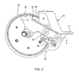
Fig. 2 is a side view of the closing wheel arrangement of the row unit ofFig. 1 with one closing wheel removed to illustrate the arrangement; -
Fig. 3 is a bottom perspective-partial sectional view of the closing wheel arrangement; -
Fig. 4 is a sectional view along the line 4-4 ofFig. 2 ; -
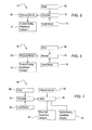
Figs. 5 and 6 are schematic diagrams of a downforce control system for the seeding machine and -
Fig. 7 is a schematic diagram of an alternative downforce control system for the seeding machine. - Referring now to the drawings, and more particularly to
FIG. 1 , there is shown a portion of aseeding machine 10. As shown,seeding machine 10 is in the form of a row crop planter but may also be other forms of machines.FIG. 1 illustrates asingle row unit 12 of a multi-row planter, with eachrow crop unit 12 being substantially identical and connected to amachine frame 14 shown as a tool bar. Only a singlerow crop unit 12 is shown and described below for sake of simplicity.Row crop unit 12 includes a multi-partrow unit frame 16 which is attached to tool bar byparallel linkage 18. The tool bar is coupled to a traction unit (not shown), such as an agricultural tractor. For example, tool bar may be coupled to an agricultural tractor using a draw bar or 3-point hitch assembly. The tool bar may be coupled with transport wheel assemblies, marker arms, etc. which may be of conventional design and not shown for clarity. -
Frame 16 carries a doubledisc furrow opener 20 for forming aseed furrow 26 insoil 27. Anoptional coulter wheel 22 androw cleaner 23, particularly for use in no till situations, may be placed ahead of doubledisc furrow opener 20. A pair of furrowdepth regulating members 25 in the form ofgauge wheels 24 are respectively associated with the pair of discs of doubledisc furrow opener 20. More particularly, eachgauge wheel 24 is positioned generally in line with and immediately adjacent to the outside of each respective disc of doubledisc furrow opener 20. Thegauge wheels 24 may be vertically adjusted to change the depth of the furrow which is cut into the soil using doubledisc furrow opener 20. - A
seed meter 32 is also carried byframe 16. Seed meter receives seed from aseed hopper 28 carried above the seed meter on theframe 16. The seed meter drive is not shown.Seed meter 32 delivers seed sequentially to aseed tube 36 through which the seed falls by gravity to thefurrow 26, or other delivery device. Afurrow closing arrangement 40 follows behind the gauge wheels with a pair ofclosing wheels 42 positioned generally in line with doubledisc furrow opener 20.Closing wheels 42 are preferably biased in a downward direction and have a peripheral edge with a shape which may vary, depending upon the application. Closingwheels 42 push soil back into thefurrow 26 upon the seeds deposited therein. Closingwheels 42 serve as a ground contacting member. - The
row unit 12 is equipped with a rowunit downforce actuator 43 in the form of an adjustablepneumatic downforce cylinder 44. The rowunit downforce actuator 43 acts between themachine frame 14 and the lower links of thelinkage 18 to apply downforce on the row unit to ensure there is a desired force of thegauge wheels 24 acting on the soil. This ensures that the doubledisc furrow opener 20 is forming thefurrow 26 to the desired depth. The amount of the downforce on the row unit, and thus the force of the soil on thegauge wheels 24, is measured by a load sensor in thepivot pin 46 in the gauge wheeldepth adjustment link 48. A suitable load sensing pin is shown inW02008/086283 A2 . Load sensors can be placed in a variety of locations on the gaugewheel support arm 49 oradjustment link 48. As described more fully below, a controller receives a signal from the load sensor in thepin 46 and controls the pressure in thecylinder 44 accordingly to achieve a desired downforce on the gauge wheels. - To ensure proper closing of the
seed furrow 26, thefurrow closing arrangement 40 provides for controlled downforce on the closing wheels. The control can be dynamic, that is changing the downforce during operation of the machine, either automatically (closed loop) or manually (open loop).Furrow closing arrangement 40 includes a mounting frame 50 (Figs. 2-4 ) attached to therow unit frame 16 at the rear thereof.Shelf 51 of themounting frame 50 is used to attach the mounting frame to therow unit frame 16. While themounting frame 50 is a separate piece, once attached to theframe 16, it functions as part of therow unit frame 16. Themounting frame 50 is a separate piece to enable other closing options to be installed in the row unit but could be integrated into theframe 16 if desired. Apivot arm 52 is rotatably coupled to the row unit frame, via themounting frame 50. Theclosing wheels 42 are mounted to thepivot arm 52. Thepivot arm 52 serves as a first link in aparallelogram linkage 54.Linkage 54 includes asecond link 56 and acoupler 58 connected to the first link, i.e.pivot arm 52, and to thesecond link 56. Apneumatic cylinder 60 is connected between themounting frame 50 and thecoupler 58 and serves as a furrow closingdownforce actuator 61. When pressure in thecylinder 60 is increased, theclosing wheels 42 exert a greater force on the soil to close thefurrow 26. - As shown in
Fig. 3 aslide member 62 connects thecoupler 58 to thepivot arm 52. This allows for a limited degree of lateral movement of thepivot arm 52 while thecylinder 60 andcoupler 58 remain fixed laterally. Thecoupler 58 only moves in a vertical direction.Fig. 4 is a sectional view through the attachment of thepivot arm 52 to the mountingframe 50. The attachment of eachleg 66 is symmetrical.Bolt 67 andnut 68 attach the leg to the mounting frame using abushing 69. Theleg 66 does not directly contact the mountingframe 50. Instead, thebushing 69 engages the mountingframe 50. Thebushing surface 70 is curved and complementary to thecurved surface 71 of the mounting frame. Thebolt 67 extends through a fore and aft extendingslot 72 in the mounting frame. The slot and thecurved surfaces pivot arm 52 to be adjusted about a vertical axis to adjust the side-to-side location of the closingwheels 42 to ensure they are center over thefurrow 26. Thebushing 69 has a projection 73 that is seated into theslot 72 to orient the bushing properly for mating of thesurfaces slide member 62 allows the pivot arm to be adjusted without affecting the location of the lower end of thecylinder 60. - The
bolt 64 that connects theslide member 62 to thepivot arm 52 can be a load sensing pin having a load sensor similar to thepin 46 mentioned above. The sensor measures the load acting on the soil from the closing wheels. Thebolt 64 is only one position of many that may be suitable for a load sensor to measure the load on the closing wheels. Any of the pivot pins in the closing wheel arrangement may be used to measure the load. Alternatively, a load cell may be attached to or integrated into the pivot arm or other links in the closing wheel arrangement. - A
control system 74 is shown schematically inFig. 5 . Acontroller 76 receives a load signal from aload sensor 78 such as thebolt 64. Aninput device 80 enables a machine operator to input a desired downforce into the controller. The controller in turn generates a signal for anair pressure source 82, causing the pressure to increase or decrease. The air pressure is then directed to the actuator, orpneumatic cylinder 60. It will be readily appreciated that thepressure source 82 could be a fixed, that is constant, pressure source and the controller connected to a regulating valve between the pressure source and thecylinder 60. As used herein, reference to the controller being operably connected to an actuator to vary the load applied to the soil is meant to mean the controller is connected to a pressure source or pressure control valve for pressure operated actuators or to an electrical control for an electric actuator. Any connection that enables the controller to operate the actuator is intended to be included. - An open
loop control system 90 is shown inFig. 6 , where like components fromcontrol system 74 are given the same reference numeral. Incontrol system 90, the controller is replace with amonitor 92. Themonitor 92 receives the output signal from theload sensor 78 and displays the load to an operator. The operator then uses theinput device 80 to control the pressure to operate the furrowclosing downforce actuator 60. As shown, the input device operates through themonitor 92. Alternatively, the operator input can be directly to thepressure source 82 or a pressure regulating valve, etc. - The control system is capable of dynamic (closed loop control) or open loop control to vary the downforce on the closing wheels with varying field conditions as the seeding machine moves through a field. Alternatively, the control system can be used to initially set the air pressure in the cylinder and then not change the pressure during operation. In such a case, the
load sensor 78 is not needed. Such a system would provide an advantage over a mechanical closing downforce system in that a single input to the controller or manual valve adjustment can adjust the closing wheel downforce on all or multiple row units without the need to manually adjust springs on each row unit individually. Oneload sensor 78, on onerow unit 12, can be used as the feedback input to control the pressure in thecylinders 60 of multiple row units on the seeding machine. In other words, a load sensor is not needed for everyrow unit 12. Perhaps one load sensor for each section of the seeding machine frame is sufficient. - Another
control system 86 is shown inFig. 7 with components common between thecontrol system 74 andcontrol system 86 given the same reference numeral and not described again.Control system 86 uses one load sensor for measuring the downforce on the row unit. The load measured by the onesensor 78 is used in the control of both the row unit downforce and the closing wheel downforce. Alternatively, two or more load sensors can may be used incontrol system 86, one measuring the load on the furrow depth regulating member and another measuring the load on the closing wheel.Control system 86 hasvalve 88 connected to thepressure source 82 and supplies pressure to both thecylinder 60 for the closing wheel downforce actuator and thecylinder 44 for the row unit downforce.Valve 82 controls the pressure independently to the twoactuators Valve 88 could be two separate valves if desired. Having two separate actuators for the row unit downforce and the furrow closing wheel downforce with independent control of the pressure to the two actuators, allows maximum flexibility to the operator in the control of row unit and closing downforce. Alternatively, a pressure regulator could be used to link and/or adjust forces between the two systems in an open-loop or closed-loop manner.Multiple cylinders controller 76 or manual adjustment. - In its simplest form, the closing wheel downforce arrangement includes an actuator operable to vary the downforce on the closing wheels as the machine moves through a field and an operator accessible switch or control to activate the actuator to vary the downforce. A load sensor and a monitor for the operator to see the measured load are optional.
- While the closing wheel downforce arrangement is disclosed and described in the context of a pneumatic cylinder used as the actuator, other actuators can be used such as a hydraulic, electronic or electro-mechanical, etc. The type of actuator is not critical. By providing control of the closing wheel downforce, the machine operator is better able to assure the seed furrow is properly closed. A pressure based actuator, pneumatic or hydraulic allows for more constant downforce across a range of loads compared to a mechanical system.
- While a pair of closing
wheels 42 have been shown, it will be appreciated that any of a variety of ground contacting members can be used in place of the closingwheels 42. Alternatives include a packing wheel, a single closing wheel, a tine type closing device or any combination thereof, etc. Additional attachments can be mounted at therear end 53 of thepivot arm 52.
Claims (10)
- A row unit (12) for a seeding machine (10) comprising: a row unit frame (16) adapted to mounted to a machine frame (14); a furrow opener (20) and a furrow depth regulating member (25) both mounted to the row unit frame (16); and a furrow closing arrangement (40) movably mounted to the row unit frame(16), characterized in that the furrow closing arrangement (40) having a ground contacting member (42), and a furrow closing downforce actuator (61) operable to vary force applied to soil by the ground contacting member (42) as the seeding machine (10) moves through a field.
- The row unit (12) of claim 1 further comprising a control system (74) including a load sensor (78) adapted to detect a load applied by the ground contacting member (42) to the soil, and a controller (76) receiving a signal from the load sensor (78), wherein the controller (76) is operably connected to the furrow closing downforce actuator (61) to vary the load applied by the ground contacting member (42) to the soil.
- The row unit (12) of claim 2 wherein the controller (76) is adapted to dynamically operate the furrow closing downforce actuator (61) to vary the load applied by the ground contacting member (42) to the soil.
- The row unit (12) of claim 1 further comprising a control system (90) including a load sensor (78) adapted to detect a load applied to the soil, a monitor (92) receiving a signal from the load sensor (78) and displaying the load to an operator and an operator input (80) to operate the furrow closing downforce actuator (61) to vary the load applied by the ground contacting member (42) to the soil.
- The row unit (12) of claim 1 wherein the furrow closing arrangement (40) includes a linkage (54) through which the ground contacting member (42) is movably mounted to the row unit frame (16).
- The row unit (12) of claim 1 wherein the furrow closing downforce actuator (61) is one of a pneumatic cylinder (60), hydraulic cylinder, and electro-mechanical actuator.
- The row unit (12) of claim 1 further comprising a linkage (18) mounting the row unit frame (16) to the machine frame (14), a row unit downforce actuator (44) operable to vary downforce on the row unit (12) and a control system (86) including at least one load sensor (78) adapted to detect a load applied to the soil, and a controller (76) receiving a signal from the load sensor (78) wherein the controller (76) is operably connected to both the row unit downforce actuator (44) and the furrow closing downforce actuator (61) to vary the load applied to the soil by the depth regulating member (25) and the ground contacting member (42).
- The row unit (12) of claim 7 wherein the control system (86) comprises two load sensors (78) with one sensor adapted to detect the load applied to the soil by the furrow depth regulating member (25) and a second load sensor adapted to detect the load applied to the soil by the ground contacting member (42).
- The row unit (12) of claim 1 wherein the furrow closing arrangement (40) includes a pivot arm (52) rotatably coupled to the row unit frame (16) with the ground contacting member (42) mounted to the pivot arm (52), the pivot arm (52) being a first link of a parallelogram linkage (54) together with a second link (56) and a coupler (58), the first and second links (52, 56) being connected to the row unit frame (16) and the coupler (58) connected to each of the first and second links (52, 56) and wherein the furrow closing downforce actuator (61) is connected between the row unit frame (16) and the coupler (58) to move the coupler (58) and thereby the pivot arm (52) to vary a load applied to the soil by the ground contacting member (42).
- The row unit (12) of claim 9 wherein the connection between the coupler (58) and the pivot arm (52) permits lateral adjustment of the pivot arm (52) relative to the coupler (58).
Applications Claiming Priority (1)
| Application Number | Priority Date | Filing Date | Title |
|---|---|---|---|
| US13/083,789 US8910582B2 (en) | 2011-04-11 | 2011-04-11 | Row unit for a seeding machine having active downforce control for the closing wheels |
Publications (2)
| Publication Number | Publication Date |
|---|---|
| EP2510768A1 true EP2510768A1 (en) | 2012-10-17 |
| EP2510768B1 EP2510768B1 (en) | 2014-04-30 |
Family
ID=45936807
Family Applications (1)
| Application Number | Title | Priority Date | Filing Date |
|---|---|---|---|
| EP20120159957 Active EP2510768B1 (en) | 2011-04-11 | 2012-03-16 | A planter row unit |
Country Status (7)
| Country | Link |
|---|---|
| US (1) | US8910582B2 (en) |
| EP (1) | EP2510768B1 (en) |
| CN (1) | CN102726148A (en) |
| AR (1) | AR085962A1 (en) |
| BR (1) | BR102012008437B1 (en) |
| ES (1) | ES2486241T3 (en) |
| RU (1) | RU2012110595A (en) |
Cited By (5)
| Publication number | Priority date | Publication date | Assignee | Title |
|---|---|---|---|---|
| US9032886B2 (en) | 2013-01-09 | 2015-05-19 | Cnh Industrial America Llc | Independent suspension for closing discs of an agricultural row unit closing assembly |
| US9826677B2 (en) | 2014-12-16 | 2017-11-28 | Cnh Industrial Canada, Ltd. | Seed implement incorporating a down pressure sensing and adjustment system |
| US10144028B2 (en) | 2014-10-30 | 2018-12-04 | Cotton Tall Industries, LLC | Agricultural spray containment devices, systems and methods |
| EP3732943A3 (en) * | 2013-11-08 | 2021-05-05 | Precision Planting LLC | Implement weight management systems, methods and apparatus |
| US12628728B2 (en) * | 2022-12-20 | 2026-05-19 | Cnh Industrial America Llc | System and method for row unit disk offset calibration |
Families Citing this family (109)
| Publication number | Priority date | Publication date | Assignee | Title |
|---|---|---|---|---|
| US10830274B2 (en) | 2007-12-21 | 2020-11-10 | Schaffert Manufacturing Company, Inc. | Seed planter with equalizer assembly |
| US7673570B1 (en) | 2008-12-01 | 2010-03-09 | Dawn Equipment Company | Row-clearing unit for agricultural implement |
| US8430179B2 (en) | 2009-04-30 | 2013-04-30 | L & B Manufacturing, Inc. | Soil tilling and planting implement |
| US9282689B2 (en) | 2009-04-30 | 2016-03-15 | L & B Manufacturing, Inc. | Soil tilling and planting implement |
| US8544398B2 (en) | 2010-09-15 | 2013-10-01 | Dawn Equipment Company | Hydraulic down pressure control system for closing wheels of an agricultural implement |
| US9055712B2 (en) | 2010-09-15 | 2015-06-16 | Dawn Equipment Company | Agricultural apparatus with integrated controller for a row unit |
| US8985232B2 (en) | 2012-08-20 | 2015-03-24 | Dawn Equipment Company | Agricultural apparatus for sensing and providing feedback of soil property changes in real time |
| US12171152B2 (en) | 2010-09-15 | 2024-12-24 | Deere & Company | System and method for adaptively controlling depth of ground-engaging planting row unit using forward sensor that measures residue ahead of row unit |
| US8763713B2 (en) | 2012-01-27 | 2014-07-01 | Dawn Equipment Company | Agricultural implement with automatic down pressure control |
| US9107338B2 (en) | 2010-09-15 | 2015-08-18 | Dawn Equipment Company | Agricultural systems |
| US9107337B2 (en) | 2012-08-20 | 2015-08-18 | Dawn Equipment Company | Agricultural apparatus for sensing and providing feedback of soil property changes in real time |
| US9226440B2 (en) | 2010-09-15 | 2016-01-05 | Dawn Equipment Company | Agricultural apparatus with hydraulic cylinder and manifold for a row unit |
| US12389816B2 (en) | 2013-02-04 | 2025-08-19 | Deere & Company | Agricultural systems |
| US8544397B2 (en) | 2010-09-15 | 2013-10-01 | Dawn Equipment Company | Row unit for agricultural implement |
| US9232687B2 (en) | 2010-09-15 | 2016-01-12 | Dawn Equipment Company | Agricultural systems |
| US8776702B2 (en) | 2010-09-15 | 2014-07-15 | Dawn Equipment Company | Hydraulic down pressure control system for an agricultural implement |
| US8863857B2 (en) | 2011-02-23 | 2014-10-21 | Dawn Equipment Company | Row unit for agricultural implement |
| EP2713690B1 (en) | 2011-06-03 | 2017-08-09 | Precision Planting LLC | Agricultural toolbar apparatus, systems, and methods |
| US9271437B2 (en) | 2011-07-01 | 2016-03-01 | Charles H. Martin | Agricultural field preparation device |
| US20130032363A1 (en) * | 2011-08-01 | 2013-02-07 | Curry Keith A | Supplemental down force system and ground working implement with same |
| UA110988C2 (en) | 2011-08-05 | 2016-03-10 | Пресіжн Плентінг Елелсі | Apparatus, systems and methods for controlling the downforce of an agricultural implement having multiple row units |
| US8636077B2 (en) | 2012-05-22 | 2014-01-28 | Dawn Equipment Company | Agricultural tool with structural housing for hydraulic actuator |
| US8910581B2 (en) | 2012-07-25 | 2014-12-16 | Dawn Equipment Company | Side dressing fertilizer coulter |
| CA3183433A1 (en) | 2012-07-25 | 2014-01-30 | Precision Planting Llc | Integrated implement downforce control systems, methods, and apparatus |
| AU2013334548B2 (en) * | 2012-10-24 | 2017-10-26 | Precision Planting Llc | Agricultural trench closing systems, methods, and apparatus |
| US9192091B2 (en) | 2013-02-01 | 2015-11-24 | Dawn Equipment Company | Agricultural apparatus with hybrid single-disk, double-disk coulter arrangement |
| US9215839B2 (en) | 2013-02-01 | 2015-12-22 | Dawn Equipment Company | Agricultural apparatus with hybrid single-disk, double-disk coulter arrangement |
| US9148989B2 (en) | 2013-02-12 | 2015-10-06 | L & B Manufacturing, Inc. | Row treating unit for agriculture implement |
| CA2867274C (en) * | 2013-11-13 | 2018-07-24 | Cnh Industrial America Llc | Agricultural tillage implement wheel control |
| ES2734984T3 (en) | 2013-12-04 | 2019-12-13 | Stoller Ets | Procedure to apply diformilurea to corn |
| US9241438B2 (en) | 2014-02-05 | 2016-01-26 | Dawn Equipment Company | Agricultural system for field preparation |
| US10721855B2 (en) | 2014-02-05 | 2020-07-28 | Dawn Equipment Company | Agricultural system for field preparation |
| US9668398B2 (en) | 2014-02-05 | 2017-06-06 | Dawn Equipment Company | Agricultural system for field preparation |
| US9615497B2 (en) | 2014-02-21 | 2017-04-11 | Dawn Equipment Company | Modular autonomous farm vehicle |
| US9750176B2 (en) | 2014-08-07 | 2017-09-05 | Cnh Industrial America Llc | Closing system for an agricultural implement |
| US20160050837A1 (en) | 2014-08-25 | 2016-02-25 | Schaffert Manufacturing Company, Inc. | Trailing arm device and assembly with parallel linkage |
| US9585302B2 (en) | 2014-09-29 | 2017-03-07 | Cnh Industrial America Llc | Closing assembly for an agricultural implement |
| US9723778B2 (en) | 2014-11-07 | 2017-08-08 | Dawn Equipment Company | Agricultural system |
| US10444774B2 (en) | 2014-11-07 | 2019-10-15 | Dawn Equipment Company | Agricultural system |
| US10582653B2 (en) | 2014-11-07 | 2020-03-10 | Dawn Equipment Company | Agricultural planting system with automatic depth control |
| US11197411B2 (en) | 2014-11-07 | 2021-12-14 | Dawn Equipment Company | Agricultural planting system with automatic depth control |
| US9848522B2 (en) | 2014-11-07 | 2017-12-26 | Dawn Equipment Company | Agricultural system |
| US9706703B2 (en) | 2014-12-11 | 2017-07-18 | Cnh Industrial America Llc | Independent closing system with adjustable down force |
| US9686900B2 (en) | 2015-06-30 | 2017-06-27 | Cnh Industrial America Llc | Convertible pinch wheel closing system for agricultural planter |
| US9918427B2 (en) | 2015-07-10 | 2018-03-20 | Cnh Industrial America Llc | Depth control system for front pivot and rear pivot gauge wheel assemblies |
| US9693496B2 (en) * | 2015-09-30 | 2017-07-04 | Deere & Company | Agricultural planting depth sensor |
| US9363938B1 (en) * | 2015-10-29 | 2016-06-14 | Donald Slagel | Strip-till row apparatus |
| US11083134B2 (en) | 2015-12-28 | 2021-08-10 | Underground Agriculture, LLC | Agricultural inter-row mowing device |
| US10477760B2 (en) | 2015-12-28 | 2019-11-19 | Underground Agriculture, LLC | Agricultural organic device for weed control |
| US10980174B2 (en) | 2015-12-28 | 2021-04-20 | Underground Agriculture, LLC | Agricultural mowing device |
| US10154621B2 (en) | 2016-01-15 | 2018-12-18 | Shoup Manufacturing Co., Inc. | Free-floating laterally adustable gauge wheel arm |
| US10798870B2 (en) | 2016-01-25 | 2020-10-13 | Schaffert Manufacturing Company, Inc. | Trailing arm device and assembly with parallel linkage |
| WO2017155962A1 (en) * | 2016-03-08 | 2017-09-14 | Harvest International, Inc. | Quick change closing wheel assembly with centering adjustment |
| CA2965005C (en) | 2016-04-22 | 2019-05-21 | Harvest International, Inc. | Row planter with adjustable gauge wheels |
| WO2017197274A1 (en) * | 2016-05-13 | 2017-11-16 | Precision Planting Llc | Seed trench closing sensors |
| AR109838A1 (en) * | 2016-10-20 | 2019-01-30 | Prec Planting Llc | COMPRESSOR WHEEL FORCE CONTROL AND AIR SEEDER PLUG WHEEL |
| BR112019006581B1 (en) * | 2016-11-03 | 2023-02-07 | Agco Corporation | ROW UNIT AND CLOSING WHEEL CONTROL SYSTEM |
| US10645860B2 (en) | 2017-03-31 | 2020-05-12 | Cnh Industrial America Llc | Seedbed condition monitoring system with a seedbed surface detection assembly |
| US10624253B2 (en) | 2017-03-31 | 2020-04-21 | Cnh Industrial America Llc | Seedbed condition monitoring system with a seedbed floor detection assembly |
| US10420272B2 (en) | 2017-03-31 | 2019-09-24 | Cnh Industrial America Llc | Seedbed condition monitoring system when performing field operations |
| US11006563B2 (en) | 2017-05-04 | 2021-05-18 | Dawn Equipment Company | Seed firming device for improving seed to soil contact in a planter furrow with feature designed to prevent the buildup of soil on the outer surfaces by discharging pressurized fluid |
| US10645865B2 (en) | 2017-05-04 | 2020-05-12 | Dawn Equipment Company | Agricultural row unit with automatic control system for furrow closing device |
| US10548260B2 (en) | 2017-05-04 | 2020-02-04 | Dawn Equipment Company | System for automatically setting the set point of a planter automatic down pressure control system with a seed furrow sidewall compaction measurement device |
| CN107295834B (en) * | 2017-07-07 | 2022-10-25 | 华中农业大学 | Ditching depth adjusting device for postposition ditching no-tillage seeder |
| US11224153B2 (en) | 2017-07-28 | 2022-01-18 | Kinze Manufacturing, Inc. | Agricultural implement and row units including double acting actuator systems, methods, and apparatus |
| BR122022021326B1 (en) * | 2017-11-15 | 2023-11-28 | Precision Planting Llc | SYSTEM FOR DETECTING CHARACTERISTICS OF A TRENCH IN A GROUND SURFACE DURING PLANTING OPERATIONS |
| US11140805B2 (en) | 2017-11-21 | 2021-10-12 | Cnh Industrial Canada, Ltd. | Independent ground engaging tool depth control |
| US11140812B2 (en) | 2017-12-15 | 2021-10-12 | Kinze Manufacturing, Inc. | Systems, methods, and apparatus for controlling downforce of an agricultural implement |
| CN107942649A (en) * | 2017-12-22 | 2018-04-20 | 中国农业大学 | With pressure automatic control system under position profiling planter |
| US11277961B2 (en) | 2018-02-09 | 2022-03-22 | Ag Leader Technology | Seed spacing device for an agricultural planter and related systems and methods |
| WO2019164919A1 (en) | 2018-02-20 | 2019-08-29 | Ag Leader Technology | Apparatus, systems and methods for applying fluid |
| EP3758466B1 (en) * | 2018-03-01 | 2025-07-16 | Precision Planting LLC | Trench closing assembly |
| CN111954461A (en) * | 2018-03-16 | 2020-11-17 | 精密种植有限责任公司 | Groove Closure Kit |
| US20190297769A1 (en) | 2018-03-30 | 2019-10-03 | Ag Leader Technology | Devices, Systems, and Methods for Seed Trench Protection |
| US10813264B2 (en) | 2018-08-10 | 2020-10-27 | Cnh Industrial America Llc | Depth control for ground engaging tools of an implement |
| US11116123B2 (en) | 2018-08-31 | 2021-09-14 | Cnh Industrial America Llc | System and method of adjusting closing disc penetration depth of a seed-planting implement |
| US10966364B2 (en) | 2018-09-04 | 2021-04-06 | Deere & Company | Work vehicle with row unit having variable steering angle |
| US11337363B2 (en) | 2018-09-28 | 2022-05-24 | Cnh Industrial America Llc | Calibrating a depth control system of a row unit in an agricultural planter |
| US12520744B2 (en) | 2018-11-15 | 2026-01-13 | Ag Leader Technology | On the go organic matter sensor and associated systems and methods |
| US11849659B2 (en) | 2018-11-20 | 2023-12-26 | Cnh Industrial America Llc | Draft load control system for an agricultural implement |
| US11357161B2 (en) | 2018-12-07 | 2022-06-14 | Harvest International, Inc. | Gauge wheel arm with split end and threaded bore |
| CN109644626B (en) * | 2019-01-09 | 2023-02-03 | 南京市同亮科技有限公司 | Millet full-film-mulching sowing device and using method |
| US11006567B2 (en) | 2019-04-18 | 2021-05-18 | Cnh Industrial America Llc | System and method for controlling the operation of a seed-planting implement based on the operation of its furrow-closing assembly |
| US11071245B2 (en) | 2019-04-25 | 2021-07-27 | Deere & Company | Seeding machine including variable force trench closer |
| US11596095B2 (en) | 2019-12-24 | 2023-03-07 | Cnh Industrial America Llc | Particle delivery system of an agricultural row unit |
| US11483963B2 (en) | 2019-12-24 | 2022-11-01 | Cnh Industrial America Llc | Particle delivery system of an agricultural row unit |
| US11553639B2 (en) | 2019-12-24 | 2023-01-17 | Cnh Industrial America Llc | Particle delivery system of an agricultural row unit |
| US11523556B2 (en) | 2019-12-24 | 2022-12-13 | Cnh Industrial America Llc | Particle delivery system of an agricultural row unit |
| US11582899B2 (en) | 2019-12-24 | 2023-02-21 | Cnh Industrial America Llc | Particle delivery system of an agricultural row unit |
| US11523555B2 (en) | 2019-12-24 | 2022-12-13 | Cnh Industrial America Llc | Particle delivery system of an agricultural row unit |
| US11564344B2 (en) | 2019-12-24 | 2023-01-31 | Cnh Industrial America Llc | Particle delivery system of an agricultural row unit |
| US11589500B2 (en) | 2019-12-24 | 2023-02-28 | Cnh Industrial America Llc | Particle delivery system of an agricultural row unit |
| US11564346B2 (en) | 2019-12-24 | 2023-01-31 | Cnh Industrial America Llc | Particle delivery system of an agricultural row unit |
| US11516958B2 (en) | 2019-12-24 | 2022-12-06 | Cnh Industrial America Llc | Particle delivery system of an agricultural row unit |
| US11490558B2 (en) | 2019-12-24 | 2022-11-08 | Cnh Industrial America Llc | Particle delivery system of an agricultural row unit |
| US11553638B2 (en) | 2019-12-24 | 2023-01-17 | Cnh Industrial America Llc | Particle delivery system of an agricultural row unit |
| US12268115B2 (en) | 2020-02-07 | 2025-04-08 | Ag Leader Technology | Planter obstruction monitoring and associated devices and methods |
| CA3122760A1 (en) | 2020-07-01 | 2022-01-01 | Cnh Industrial Canada, Ltd. | Seeder row unit having a closing system |
| CA3122771A1 (en) | 2020-07-01 | 2022-01-01 | Cnh Industrial Canada, Ltd. | Seeder row unit having a closing system |
| US12477973B2 (en) | 2020-11-13 | 2025-11-25 | Ag Leader Technology | Agricultural high speed row unit |
| US12075721B2 (en) | 2021-05-27 | 2024-09-03 | Cnh Industrial Canada, Ltd. | Systems and methods for downforce control for an implement |
| WO2023004383A1 (en) | 2021-07-21 | 2023-01-26 | Kinze Manufacturing, Inc. | A row unit component for agricultural implements |
| US12484472B2 (en) * | 2021-12-23 | 2025-12-02 | Cnh Industrial Canada, Ltd. | Penetration depth control and gauge wheel contact force monitoring system for an agricultural row unit |
| US12622342B2 (en) | 2022-01-14 | 2026-05-12 | Schaffert Manufacturing Company, Inc. | Modular wheel assembly |
| CN114503801B (en) * | 2022-02-14 | 2023-11-14 | 吉林大学 | High-speed stubble-pulling monomer capable of automatically regulating and controlling soil penetration depth |
| US20240167998A1 (en) * | 2022-11-18 | 2024-05-23 | Deere & Company | Machine control based on measured soil strength |
| US12543615B2 (en) * | 2022-11-18 | 2026-02-10 | Deere & Company | Generating soil strength metric during row unit operation and controlling row unit |
| US20240244990A1 (en) * | 2023-01-23 | 2024-07-25 | Deere & Company | Closed loop closing system control |
| AR131699A1 (en) | 2024-01-25 | 2025-04-23 | Jorge Alberto Gentili | SOWING TRAIN FOR DIRECT SEEDING |
Citations (4)
| Publication number | Priority date | Publication date | Assignee | Title |
|---|---|---|---|---|
| EP0140263A1 (en) | 1983-10-28 | 1985-05-08 | Deere & Company | Drilling device for a seeder |
| CA2549371A1 (en) * | 2006-05-23 | 2007-11-23 | William R. Ritchie | A ground opening device |
| US20110313572A1 (en) * | 2010-06-22 | 2011-12-22 | Trevor Kowalchuk | Automatic Down Pressure Adjustment System For Set Of Ganged Disc Openers |
| US20120048159A1 (en) * | 2010-08-30 | 2012-03-01 | Cnh America Llc | Manual backup system for controlling fluid flow to cylinders within an agricultural implement |
Family Cites Families (16)
| Publication number | Priority date | Publication date | Assignee | Title |
|---|---|---|---|---|
| NZ227221A (en) | 1988-12-06 | 1992-11-25 | Univ Massey | Maintaining seed drill opener at constant depth by constantly monitoring soil reaction force on gauge wheel |
| US5375542A (en) * | 1993-04-20 | 1994-12-27 | Schaffert; Paul E. | Seed covering apparatus |
| US5479992A (en) | 1993-07-27 | 1996-01-02 | Dawn Equipment Company | Agricultural implement controller to compensate for soil hardness variation |
| US5497837A (en) * | 1994-03-31 | 1996-03-12 | Dawn Equipment Company | Apparatus for controlling down pressure on agricultural implements |
| US6389999B1 (en) | 2001-11-02 | 2002-05-21 | Dennis Duello | Dynamic controller of excess downpressure for surface engaging implement |
| US6701857B1 (en) | 2003-01-16 | 2004-03-09 | Lynn David Jensen | Depth control device for planting implement |
| PL2104413T5 (en) | 2007-01-08 | 2020-07-13 | The Climate Corporation | Planter monitor system and method |
| US8561472B2 (en) | 2007-01-08 | 2013-10-22 | Precision Planting Llc | Load sensing pin |
| CA2581613A1 (en) | 2007-03-13 | 2008-09-13 | Straw Track Manufacturing Inc. | Packing for planters |
| CA2587130C (en) * | 2007-04-17 | 2008-07-22 | Dick Edward Friesen | Double shoot disc opener |
| CA2594032C (en) | 2007-07-18 | 2015-01-27 | Bourgault Industries Ltd. | Method and device for adjusting and controlling packing force |
| US7401561B1 (en) * | 2007-08-16 | 2008-07-22 | Kurz Clare D | Suspension system for a row crop planter unit |
| LT2193352T (en) | 2007-09-26 | 2017-05-10 | Precision Planting Llc | System and method for determining proper downforce for a planter row unit |
| US7673570B1 (en) | 2008-12-01 | 2010-03-09 | Dawn Equipment Company | Row-clearing unit for agricultural implement |
| FR2939599A1 (en) * | 2008-12-15 | 2010-06-18 | Exel Ind | Seed drill element for agricultural seeder used with tractor, has adjusting unit for adjusting angle formed between small upstream side of parallelogram and small downstream side of another parallelogram |
| CN101946576B (en) * | 2010-06-23 | 2012-05-30 | 中国农业大学 | Automatic control system for ditching depth of disc type ditcher |
-
2011
- 2011-04-11 US US13/083,789 patent/US8910582B2/en active Active
-
2012
- 2012-03-16 EP EP20120159957 patent/EP2510768B1/en active Active
- 2012-03-16 ES ES12159957.5T patent/ES2486241T3/en active Active
- 2012-03-20 RU RU2012110595/13A patent/RU2012110595A/en not_active Application Discontinuation
- 2012-04-09 CN CN2012101020304A patent/CN102726148A/en active Pending
- 2012-04-10 AR ARP120101221 patent/AR085962A1/en active IP Right Grant
- 2012-04-10 BR BR102012008437-6A patent/BR102012008437B1/en active IP Right Grant
Patent Citations (4)
| Publication number | Priority date | Publication date | Assignee | Title |
|---|---|---|---|---|
| EP0140263A1 (en) | 1983-10-28 | 1985-05-08 | Deere & Company | Drilling device for a seeder |
| CA2549371A1 (en) * | 2006-05-23 | 2007-11-23 | William R. Ritchie | A ground opening device |
| US20110313572A1 (en) * | 2010-06-22 | 2011-12-22 | Trevor Kowalchuk | Automatic Down Pressure Adjustment System For Set Of Ganged Disc Openers |
| US20120048159A1 (en) * | 2010-08-30 | 2012-03-01 | Cnh America Llc | Manual backup system for controlling fluid flow to cylinders within an agricultural implement |
Cited By (5)
| Publication number | Priority date | Publication date | Assignee | Title |
|---|---|---|---|---|
| US9032886B2 (en) | 2013-01-09 | 2015-05-19 | Cnh Industrial America Llc | Independent suspension for closing discs of an agricultural row unit closing assembly |
| EP3732943A3 (en) * | 2013-11-08 | 2021-05-05 | Precision Planting LLC | Implement weight management systems, methods and apparatus |
| US10144028B2 (en) | 2014-10-30 | 2018-12-04 | Cotton Tall Industries, LLC | Agricultural spray containment devices, systems and methods |
| US9826677B2 (en) | 2014-12-16 | 2017-11-28 | Cnh Industrial Canada, Ltd. | Seed implement incorporating a down pressure sensing and adjustment system |
| US12628728B2 (en) * | 2022-12-20 | 2026-05-19 | Cnh Industrial America Llc | System and method for row unit disk offset calibration |
Also Published As
| Publication number | Publication date |
|---|---|
| ES2486241T3 (en) | 2014-08-18 |
| US8910582B2 (en) | 2014-12-16 |
| RU2012110595A (en) | 2013-09-27 |
| BR102012008437B1 (en) | 2018-11-06 |
| BR102012008437A2 (en) | 2013-06-11 |
| CN102726148A (en) | 2012-10-17 |
| EP2510768B1 (en) | 2014-04-30 |
| AR085962A1 (en) | 2013-11-06 |
| US20120255475A1 (en) | 2012-10-11 |
Similar Documents
| Publication | Publication Date | Title |
|---|---|---|
| EP2510768B1 (en) | A planter row unit | |
| US11617295B2 (en) | Dynamic supplemental downforce control system for planter row units | |
| EP4218378B1 (en) | An agricultural planter row unit with a fluid control system | |
| EP2554036A1 (en) | A supplemental down force system and ground working implement with same | |
| EP2701482B1 (en) | Down and/or up force adjustment system | |
| US9198343B2 (en) | Implement weight transfer with feedback control | |
| CA2929592C (en) | Implement weight management systems, methods, and apparatus | |
| CA2927387A1 (en) | Convertible pinch wheel closing system for agricultural planter | |
| EP3815503A1 (en) | Implement having weight transfer system and method of operating the same | |
| US11284554B2 (en) | Method of controlling weight transfer of an implement and system thereof | |
| CA3001409C (en) | Stacking planter toolbar without four-bar linkage | |
| US20230110072A1 (en) | Row cleaner diverter |
Legal Events
| Date | Code | Title | Description |
|---|---|---|---|
| PUAI | Public reference made under article 153(3) epc to a published international application that has entered the european phase |
Free format text: ORIGINAL CODE: 0009012 |
|
| AK | Designated contracting states |
Kind code of ref document: A1 Designated state(s): AL AT BE BG CH CY CZ DE DK EE ES FI FR GB GR HR HU IE IS IT LI LT LU LV MC MK MT NL NO PL PT RO RS SE SI SK SM TR |
|
| AX | Request for extension of the european patent |
Extension state: BA ME |
|
| 17P | Request for examination filed |
Effective date: 20130417 |
|
| GRAP | Despatch of communication of intention to grant a patent |
Free format text: ORIGINAL CODE: EPIDOSNIGR1 |
|
| RIC1 | Information provided on ipc code assigned before grant |
Ipc: A01C 5/06 20060101AFI20131025BHEP Ipc: A01C 7/20 20060101ALI20131025BHEP |
|
| INTG | Intention to grant announced |
Effective date: 20131114 |
|
| GRAS | Grant fee paid |
Free format text: ORIGINAL CODE: EPIDOSNIGR3 |
|
| GRAA | (expected) grant |
Free format text: ORIGINAL CODE: 0009210 |
|
| AK | Designated contracting states |
Kind code of ref document: B1 Designated state(s): AL AT BE BG CH CY CZ DE DK EE ES FI FR GB GR HR HU IE IS IT LI LT LU LV MC MK MT NL NO PL PT RO RS SE SI SK SM TR |
|
| REG | Reference to a national code |
Ref country code: GB Ref legal event code: FG4D Ref country code: CH Ref legal event code: EP |
|
| REG | Reference to a national code |
Ref country code: AT Ref legal event code: REF Ref document number: 664476 Country of ref document: AT Kind code of ref document: T Effective date: 20140515 |
|
| REG | Reference to a national code |
Ref country code: IE Ref legal event code: FG4D |
|
| REG | Reference to a national code |
Ref country code: DE Ref legal event code: R096 Ref document number: 602012001526 Country of ref document: DE Effective date: 20140612 |
|
| REG | Reference to a national code |
Ref country code: ES Ref legal event code: FG2A Ref document number: 2486241 Country of ref document: ES Kind code of ref document: T3 Effective date: 20140818 |
|
| REG | Reference to a national code |
Ref country code: AT Ref legal event code: MK05 Ref document number: 664476 Country of ref document: AT Kind code of ref document: T Effective date: 20140430 |
|
| REG | Reference to a national code |
Ref country code: LT Ref legal event code: MG4D |
|
| REG | Reference to a national code |
Ref country code: NL Ref legal event code: VDEP Effective date: 20140430 |
|
| PG25 | Lapsed in a contracting state [announced via postgrant information from national office to epo] |
Ref country code: NO Free format text: LAPSE BECAUSE OF FAILURE TO SUBMIT A TRANSLATION OF THE DESCRIPTION OR TO PAY THE FEE WITHIN THE PRESCRIBED TIME-LIMIT Effective date: 20140730 Ref country code: LT Free format text: LAPSE BECAUSE OF FAILURE TO SUBMIT A TRANSLATION OF THE DESCRIPTION OR TO PAY THE FEE WITHIN THE PRESCRIBED TIME-LIMIT Effective date: 20140430 Ref country code: NL Free format text: LAPSE BECAUSE OF FAILURE TO SUBMIT A TRANSLATION OF THE DESCRIPTION OR TO PAY THE FEE WITHIN THE PRESCRIBED TIME-LIMIT Effective date: 20140430 Ref country code: GR Free format text: LAPSE BECAUSE OF FAILURE TO SUBMIT A TRANSLATION OF THE DESCRIPTION OR TO PAY THE FEE WITHIN THE PRESCRIBED TIME-LIMIT Effective date: 20140731 Ref country code: FI Free format text: LAPSE BECAUSE OF FAILURE TO SUBMIT A TRANSLATION OF THE DESCRIPTION OR TO PAY THE FEE WITHIN THE PRESCRIBED TIME-LIMIT Effective date: 20140430 Ref country code: IS Free format text: LAPSE BECAUSE OF FAILURE TO SUBMIT A TRANSLATION OF THE DESCRIPTION OR TO PAY THE FEE WITHIN THE PRESCRIBED TIME-LIMIT Effective date: 20140830 Ref country code: CY Free format text: LAPSE BECAUSE OF FAILURE TO SUBMIT A TRANSLATION OF THE DESCRIPTION OR TO PAY THE FEE WITHIN THE PRESCRIBED TIME-LIMIT Effective date: 20140430 Ref country code: BG Free format text: LAPSE BECAUSE OF FAILURE TO SUBMIT A TRANSLATION OF THE DESCRIPTION OR TO PAY THE FEE WITHIN THE PRESCRIBED TIME-LIMIT Effective date: 20140730 |
|
| PG25 | Lapsed in a contracting state [announced via postgrant information from national office to epo] |
Ref country code: AT Free format text: LAPSE BECAUSE OF FAILURE TO SUBMIT A TRANSLATION OF THE DESCRIPTION OR TO PAY THE FEE WITHIN THE PRESCRIBED TIME-LIMIT Effective date: 20140430 Ref country code: RS Free format text: LAPSE BECAUSE OF FAILURE TO SUBMIT A TRANSLATION OF THE DESCRIPTION OR TO PAY THE FEE WITHIN THE PRESCRIBED TIME-LIMIT Effective date: 20140430 Ref country code: PL Free format text: LAPSE BECAUSE OF FAILURE TO SUBMIT A TRANSLATION OF THE DESCRIPTION OR TO PAY THE FEE WITHIN THE PRESCRIBED TIME-LIMIT Effective date: 20140430 Ref country code: HR Free format text: LAPSE BECAUSE OF FAILURE TO SUBMIT A TRANSLATION OF THE DESCRIPTION OR TO PAY THE FEE WITHIN THE PRESCRIBED TIME-LIMIT Effective date: 20140430 Ref country code: SE Free format text: LAPSE BECAUSE OF FAILURE TO SUBMIT A TRANSLATION OF THE DESCRIPTION OR TO PAY THE FEE WITHIN THE PRESCRIBED TIME-LIMIT Effective date: 20140430 Ref country code: LV Free format text: LAPSE BECAUSE OF FAILURE TO SUBMIT A TRANSLATION OF THE DESCRIPTION OR TO PAY THE FEE WITHIN THE PRESCRIBED TIME-LIMIT Effective date: 20140430 |
|
| PG25 | Lapsed in a contracting state [announced via postgrant information from national office to epo] |
Ref country code: PT Free format text: LAPSE BECAUSE OF FAILURE TO SUBMIT A TRANSLATION OF THE DESCRIPTION OR TO PAY THE FEE WITHIN THE PRESCRIBED TIME-LIMIT Effective date: 20140901 |
|
| PG25 | Lapsed in a contracting state [announced via postgrant information from national office to epo] |
Ref country code: EE Free format text: LAPSE BECAUSE OF FAILURE TO SUBMIT A TRANSLATION OF THE DESCRIPTION OR TO PAY THE FEE WITHIN THE PRESCRIBED TIME-LIMIT Effective date: 20140430 Ref country code: BE Free format text: LAPSE BECAUSE OF FAILURE TO SUBMIT A TRANSLATION OF THE DESCRIPTION OR TO PAY THE FEE WITHIN THE PRESCRIBED TIME-LIMIT Effective date: 20140430 Ref country code: CZ Free format text: LAPSE BECAUSE OF FAILURE TO SUBMIT A TRANSLATION OF THE DESCRIPTION OR TO PAY THE FEE WITHIN THE PRESCRIBED TIME-LIMIT Effective date: 20140430 Ref country code: RO Free format text: LAPSE BECAUSE OF FAILURE TO SUBMIT A TRANSLATION OF THE DESCRIPTION OR TO PAY THE FEE WITHIN THE PRESCRIBED TIME-LIMIT Effective date: 20140430 Ref country code: DK Free format text: LAPSE BECAUSE OF FAILURE TO SUBMIT A TRANSLATION OF THE DESCRIPTION OR TO PAY THE FEE WITHIN THE PRESCRIBED TIME-LIMIT Effective date: 20140430 Ref country code: SK Free format text: LAPSE BECAUSE OF FAILURE TO SUBMIT A TRANSLATION OF THE DESCRIPTION OR TO PAY THE FEE WITHIN THE PRESCRIBED TIME-LIMIT Effective date: 20140430 |
|
| REG | Reference to a national code |
Ref country code: DE Ref legal event code: R097 Ref document number: 602012001526 Country of ref document: DE |
|
| PLBE | No opposition filed within time limit |
Free format text: ORIGINAL CODE: 0009261 |
|
| STAA | Information on the status of an ep patent application or granted ep patent |
Free format text: STATUS: NO OPPOSITION FILED WITHIN TIME LIMIT |
|
| 26N | No opposition filed |
Effective date: 20150202 |
|
| PGFP | Annual fee paid to national office [announced via postgrant information from national office to epo] |
Ref country code: IT Payment date: 20150331 Year of fee payment: 4 |
|
| REG | Reference to a national code |
Ref country code: DE Ref legal event code: R097 Ref document number: 602012001526 Country of ref document: DE Effective date: 20150202 |
|
| PG25 | Lapsed in a contracting state [announced via postgrant information from national office to epo] |
Ref country code: SI Free format text: LAPSE BECAUSE OF FAILURE TO SUBMIT A TRANSLATION OF THE DESCRIPTION OR TO PAY THE FEE WITHIN THE PRESCRIBED TIME-LIMIT Effective date: 20140430 |
|
| REG | Reference to a national code |
Ref country code: DE Ref legal event code: R119 Ref document number: 602012001526 Country of ref document: DE |
|
| PG25 | Lapsed in a contracting state [announced via postgrant information from national office to epo] |
Ref country code: LU Free format text: LAPSE BECAUSE OF FAILURE TO SUBMIT A TRANSLATION OF THE DESCRIPTION OR TO PAY THE FEE WITHIN THE PRESCRIBED TIME-LIMIT Effective date: 20150316 Ref country code: MC Free format text: LAPSE BECAUSE OF FAILURE TO SUBMIT A TRANSLATION OF THE DESCRIPTION OR TO PAY THE FEE WITHIN THE PRESCRIBED TIME-LIMIT Effective date: 20140430 |
|
| REG | Reference to a national code |
Ref country code: CH Ref legal event code: PL |
|
| REG | Reference to a national code |
Ref country code: IE Ref legal event code: MM4A |
|
| PG25 | Lapsed in a contracting state [announced via postgrant information from national office to epo] |
Ref country code: DE Free format text: LAPSE BECAUSE OF NON-PAYMENT OF DUE FEES Effective date: 20151001 Ref country code: IE Free format text: LAPSE BECAUSE OF NON-PAYMENT OF DUE FEES Effective date: 20150316 Ref country code: CH Free format text: LAPSE BECAUSE OF NON-PAYMENT OF DUE FEES Effective date: 20150331 Ref country code: LI Free format text: LAPSE BECAUSE OF NON-PAYMENT OF DUE FEES Effective date: 20150331 |
|
| REG | Reference to a national code |
Ref country code: FR Ref legal event code: PLFP Year of fee payment: 5 |
|
| GBPC | Gb: european patent ceased through non-payment of renewal fee |
Effective date: 20160316 |
|
| PG25 | Lapsed in a contracting state [announced via postgrant information from national office to epo] |
Ref country code: MT Free format text: LAPSE BECAUSE OF FAILURE TO SUBMIT A TRANSLATION OF THE DESCRIPTION OR TO PAY THE FEE WITHIN THE PRESCRIBED TIME-LIMIT Effective date: 20140430 |
|
| PG25 | Lapsed in a contracting state [announced via postgrant information from national office to epo] |
Ref country code: GB Free format text: LAPSE BECAUSE OF NON-PAYMENT OF DUE FEES Effective date: 20160316 |
|
| PG25 | Lapsed in a contracting state [announced via postgrant information from national office to epo] |
Ref country code: IT Free format text: LAPSE BECAUSE OF NON-PAYMENT OF DUE FEES Effective date: 20160316 |
|
| REG | Reference to a national code |
Ref country code: FR Ref legal event code: PLFP Year of fee payment: 6 |
|
| PG25 | Lapsed in a contracting state [announced via postgrant information from national office to epo] |
Ref country code: SM Free format text: LAPSE BECAUSE OF FAILURE TO SUBMIT A TRANSLATION OF THE DESCRIPTION OR TO PAY THE FEE WITHIN THE PRESCRIBED TIME-LIMIT Effective date: 20140430 Ref country code: HU Free format text: LAPSE BECAUSE OF FAILURE TO SUBMIT A TRANSLATION OF THE DESCRIPTION OR TO PAY THE FEE WITHIN THE PRESCRIBED TIME-LIMIT; INVALID AB INITIO Effective date: 20120316 |
|
| PG25 | Lapsed in a contracting state [announced via postgrant information from national office to epo] |
Ref country code: TR Free format text: LAPSE BECAUSE OF FAILURE TO SUBMIT A TRANSLATION OF THE DESCRIPTION OR TO PAY THE FEE WITHIN THE PRESCRIBED TIME-LIMIT Effective date: 20140430 |
|
| REG | Reference to a national code |
Ref country code: FR Ref legal event code: PLFP Year of fee payment: 7 |
|
| PG25 | Lapsed in a contracting state [announced via postgrant information from national office to epo] |
Ref country code: MK Free format text: LAPSE BECAUSE OF FAILURE TO SUBMIT A TRANSLATION OF THE DESCRIPTION OR TO PAY THE FEE WITHIN THE PRESCRIBED TIME-LIMIT Effective date: 20140430 |
|
| PG25 | Lapsed in a contracting state [announced via postgrant information from national office to epo] |
Ref country code: AL Free format text: LAPSE BECAUSE OF FAILURE TO SUBMIT A TRANSLATION OF THE DESCRIPTION OR TO PAY THE FEE WITHIN THE PRESCRIBED TIME-LIMIT Effective date: 20140430 |
|
| PGFP | Annual fee paid to national office [announced via postgrant information from national office to epo] |
Ref country code: ES Payment date: 20240401 Year of fee payment: 13 |
|
| PGFP | Annual fee paid to national office [announced via postgrant information from national office to epo] |
Ref country code: FR Payment date: 20260325 Year of fee payment: 15 |
|
| REG | Reference to a national code |
Ref country code: ES Ref legal event code: FD2A Effective date: 20260504 |