EP2509829B1 - Remote control assembly installed in airbag module - Google Patents
Remote control assembly installed in airbag module Download PDFInfo
- Publication number
- EP2509829B1 EP2509829B1 EP10836172.6A EP10836172A EP2509829B1 EP 2509829 B1 EP2509829 B1 EP 2509829B1 EP 10836172 A EP10836172 A EP 10836172A EP 2509829 B1 EP2509829 B1 EP 2509829B1
- Authority
- EP
- European Patent Office
- Prior art keywords
- remote control
- control switch
- block
- adapter
- fixing
- Prior art date
- Legal status (The legal status is an assumption and is not a legal conclusion. Google has not performed a legal analysis and makes no representation as to the accuracy of the status listed.)
- Active
Links
Images



Classifications
-
- B—PERFORMING OPERATIONS; TRANSPORTING
- B60—VEHICLES IN GENERAL
- B60R—VEHICLES, VEHICLE FITTINGS, OR VEHICLE PARTS, NOT OTHERWISE PROVIDED FOR
- B60R21/00—Arrangements or fittings on vehicles for protecting or preventing injuries to occupants or pedestrians in case of accidents or other traffic risks
- B60R21/02—Occupant safety arrangements or fittings, e.g. crash pads
- B60R21/16—Inflatable occupant restraints or confinements designed to inflate upon impact or impending impact, e.g. air bags
- B60R21/20—Arrangements for storing inflatable members in their non-use or deflated condition; Arrangement or mounting of air bag modules or components
- B60R21/215—Arrangements for storing inflatable members in their non-use or deflated condition; Arrangement or mounting of air bag modules or components characterised by the covers for the inflatable member
- B60R21/2165—Arrangements for storing inflatable members in their non-use or deflated condition; Arrangement or mounting of air bag modules or components characterised by the covers for the inflatable member characterised by a tear line for defining a deployment opening
- B60R21/21656—Steering wheel covers or similar cup-shaped covers
- B60R21/21658—Steering wheel covers or similar cup-shaped covers with integrated switches, e.g. horn switches
-
- B—PERFORMING OPERATIONS; TRANSPORTING
- B60—VEHICLES IN GENERAL
- B60R—VEHICLES, VEHICLE FITTINGS, OR VEHICLE PARTS, NOT OTHERWISE PROVIDED FOR
- B60R16/00—Electric or fluid circuits specially adapted for vehicles and not otherwise provided for; Arrangement of elements of electric or fluid circuits specially adapted for vehicles and not otherwise provided for
- B60R16/02—Electric or fluid circuits specially adapted for vehicles and not otherwise provided for; Arrangement of elements of electric or fluid circuits specially adapted for vehicles and not otherwise provided for electric constitutive elements
-
- B—PERFORMING OPERATIONS; TRANSPORTING
- B60—VEHICLES IN GENERAL
- B60R—VEHICLES, VEHICLE FITTINGS, OR VEHICLE PARTS, NOT OTHERWISE PROVIDED FOR
- B60R21/00—Arrangements or fittings on vehicles for protecting or preventing injuries to occupants or pedestrians in case of accidents or other traffic risks
- B60R21/02—Occupant safety arrangements or fittings, e.g. crash pads
- B60R21/16—Inflatable occupant restraints or confinements designed to inflate upon impact or impending impact, e.g. air bags
-
- B—PERFORMING OPERATIONS; TRANSPORTING
- B60—VEHICLES IN GENERAL
- B60R—VEHICLES, VEHICLE FITTINGS, OR VEHICLE PARTS, NOT OTHERWISE PROVIDED FOR
- B60R21/00—Arrangements or fittings on vehicles for protecting or preventing injuries to occupants or pedestrians in case of accidents or other traffic risks
- B60R21/02—Occupant safety arrangements or fittings, e.g. crash pads
- B60R21/16—Inflatable occupant restraints or confinements designed to inflate upon impact or impending impact, e.g. air bags
- B60R21/20—Arrangements for storing inflatable members in their non-use or deflated condition; Arrangement or mounting of air bag modules or components
- B60R21/215—Arrangements for storing inflatable members in their non-use or deflated condition; Arrangement or mounting of air bag modules or components characterised by the covers for the inflatable member
-
- H—ELECTRICITY
- H01—ELECTRIC ELEMENTS
- H01H—ELECTRIC SWITCHES; RELAYS; SELECTORS; EMERGENCY PROTECTIVE DEVICES
- H01H9/00—Details of switching devices, not covered by groups H01H1/00 - H01H7/00
-
- H—ELECTRICITY
- H01—ELECTRIC ELEMENTS
- H01H—ELECTRIC SWITCHES; RELAYS; SELECTORS; EMERGENCY PROTECTIVE DEVICES
- H01H9/00—Details of switching devices, not covered by groups H01H1/00 - H01H7/00
- H01H9/02—Bases, casings, or covers
- H01H9/0214—Hand-held casings
- H01H9/0235—Hand-held casings specially adapted for remote control, e.g. of audio or video apparatus
Definitions
- the present invention relates to a remote control assembly installed in an airbag module for a vehicle. More particularly, the present invention relates to a remote control switch installed in an airbag module, capable of solving the problem occurring in an integral-type remote control switch, which may not be independently exchanged upon the failure thereof, wherein a detachable block adapter is provided to allow the remote control switch installed in the airbag module to be simply exchanged with new one by separating the detachable block adapter from a fixing plate such that a worker can replace only the remote control switch by picking up the remote control switch upon the failure of the remote control switch.
- the present invention relates to a remote control assembly having a block adapter including an upper block and a lower block, in which a thickness of the block adapter can be elastically adjusted by an elastic member interposed between the upper and lower blocks, so that a remote control switch can be instantly exchanged with new one by releasing a fastening bolt upon the failure of the remote control switch.
- a vehicle is regarded as a transportation means as well as a living necessary in modem society.
- various accessory devices are installed in the vehicle for the purpose of convenience of users.
- various luxurious accessory devices such as an audio device, a remote control key, a remote control ignition device, a rear-side collision sensor, an A/V system, and a navigation system, have been provided for the vehicle.
- a seat belt is employed and the collision analysis is performed to improve the design of the vehicle structure.
- an airbag device is provided together with the seat belt to restrain the movement of the occupants and to attenuate the impact upon the vehicle collision, thereby protecting the occupants more safely.
- the rate of vehicles equipped with airbag devices is very high in North America and Europe, and this rate is gradually increased in Korea.
- an airbag module is installed in the airbag system.
- the airbag module includes a remote control switch, which is independently operated.
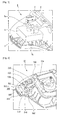
- FIG. 1 is a perspective view showing a remote control assembly 1, that is, an airbag remote control module installed in an airbag module according to the related art.
- the remote control assembly 1 according to the related art includes an integral-type remote control switch 2 accommodated in a remote control switch mounting part 3a of an airbag module cover 3.
- the integral-type remote control switch 2 is fixedly restrained in the remote control switch mounting part 3a such that the integral-type remote control switch 2 may not move in the front, rear, left and right directions.
- the integral-type remote control switch 2 is firmly fixed to a remote control switch fixing part 5, which is integrally formed with a fixing plate 4, by a fastening bolt 5a.
- the integral-type remote control switch 2 when the integral-type remote control switch 2 is damaged, the integral-type remote control switch 2 may not be independently separated from the airbag module, so that the airbag module must be exchanged.
- the remote control switch 2 is integrally formed so that the remote control assembly 1 must be exchanged even if only the remote control switch 2 is damaged or broken, thereby causing inefficiency in terms of economy and labor force.
- the remote control assembly 1 is very expensive, so the remote control assembly 1 may not be extensively used.
- the remote control switch 2 of the remote control assembly 1 is equipped with an electronic circuit, so the remote control switch 2 may be frequently damaged or broken under the external environment as compared with other components. Therefore, it is very inefficient in terms of economy if the remote control assembly 1 must be exchanged when the remote control switch 2 is damaged or broken.
- the remote control switch 2 is a component of the remote control assembly 1, the cost of the remote control switch 2 is inexpensive than the cost of the remote control assembly 1, so it is very inefficient if the remote control assembly 1 is exchanged when the remote control switch 2 is damaged or broken.
- a remote control assembly according to the related art is disclosed in US 5,085,461 , for example.
- the present invention has been made to solve the problems occurring in the related art, and an object of the present invention is to provide a remote control assembly installed in an airbag module, capable of improving the economic efficiency by providing a detachable block adapter to simply exchange only a remote control switch when the remote control switch is damaged or broken.
- Another object of the present invention is to provide a remote control assembly installed in an airbag module, in which a block adapter includes an upper block and a lower block such that a thickness of the block adapter can be elastically adjusted by an elastic member interposed between the upper and lower blocks, so that only a remote control switch can be easily exchanged with new one without exchanging the remote control assembly, which is expensive about five to six times as compared with the remote control switch, by picking up the remote control switch upon the failure of the remote control switch.
- Still another object of the present invention is to provide a remote control assembly installed in an airbag module, in which a locking jaw and a locking protrusion are provided to prevent an upper block and a lower block of a block adapter from being separated from each other even if a remote control switch can be removed from the remote control assembly by picking up the remote control switch without separately disassembling the block adapter.
- the present invention provides embodiments having the following structure.
- a remote control assembly installed in an airbag module for a vehicle.
- the remote control assembly includes a cover for covering a whole area of the airbag module; a remote control switch installed in the cover, to fixing plate for fixing components installed in the airbag module; and a block adapter installed between the remote control switch and the fixing plate to separate the remote control switch.
- the fixing plate includes an adapter fixing member having a first fixing hole
- the block adapter includes a second fixing hole corresponding to the first fixing hole of the adapter fixing member
- the block adapter is detachably fixed to the fixing plate by a fastening bolt.
- the block adapter includes a remote control switch coupling part having a first coupling hole
- the remote control switch includes a second coupling hole corresponding to the first coupling hole of the remote control switch coupling part
- the remote control switch is detachably fixed to the block adapter by a fastening bolt.
- the cover includes a remote control switch mounting part into which the remote control switch is received.
- the block adapter includes: an upper block detachably fixed to the fixing plate; a lower block detachably fixed to the remote control switch; and an elastic member interposed between the upper and lower blocks.
- the upper block is provided at a lower portion thereof with a receiving part for receiving the lower block
- the lower block includes a remote control switch coupling part.
- a recess is formed at an upper portion of the lower block to receive the elastic member.
- the lower block is reccived in the upper block, and the elastic member is interposed between the upper and lower blocks to elastically support the upper and lower blocks.
- the second fixing hole is formed in the upper block and the remote control switch coupling part is provided at the lower block.
- the upper block includes a locking jaw for preventing the upper block from being separated from the lower block
- the lower block includes a locking protrusion for preventing the lower block from being separated from the upper block.
- the present invention has the following effects.
- the detachable block adapter is provided to exchange only the remote control switch installed in the airbag module without exchanging the airbag module upon the failure or the remote control switch, so that the economic efficiency can be improved.
- the block adapter includes the upper block and the lower block such that the thickness of the block adapter can be elastically adjusted by the elastic member interposed between the upper and lower blocks, so that only the remote control switch can be easily exchanged with new one without exchanging the remote control assembly, which is expensive about five to six times as compared with the remote control switch, by picking up the remote control switch upon the failure of the remote control switch.
- the remote control switch installed in the remote control assembly can be easily exchanged, the remote control switch can be sold in the market as a singular product, so that the market for vehicle components can be activated and the economic efficiency can be improved.
- the block adapter includes the upper block and the lower block and the thickness of the block adapter can be elastically adjusted, so that the remote control switch can be easily and simply disassembled and exchanged without disassembling the block adapter.
- the upper block and the lower block of the block adapter are elastically compressed against each other, so the remote control switch can be pushed upward by the upper block and the lower block, so that the remote control switch can be easily disassembled.
- the locking jaw is formed at the upper block and the locking protrusion is formed at the lower block to prevent the upper block and the lower block from being separated from each other, thereby facilitating the exchange work for the remote control switch.
- the airbag module is assembled by the fastening bolt (screw bolt) and the detachable block adapter is provided between the body of the remote control switch and the fixing plate of the airbag module, so that the simple structure can be achieved at the low cost.
- it is easy to exchange or repair individual components of the remote control assembly when the individual components are damaged or broken, so that the convenience of use for the remote control assembly can be improved.
- the remote control switch can be detachably fixed by providing the block adapter and modifying the structure and shape of the fixing plate for restraining the remote control switch.
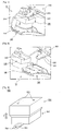
- FIG. 2 is a perspective view showing the remote control assembly installed in the airbag module according to the present invention
- FIG. 3 is a perspective view showing the remote control switch protruding from the front surface of the remote control assembly
- FIG. 4 is a view showing the structure of the remote control switch according to the present invention.
- the remote control assembly 10 installed in the airbag module for a vehicle includes a cover for covering a whole area of the airbag module; a remote control switch installed in the cover; a fixing plate for fixing components installed in the airbag module; and a block adapter installed between the remote control switch and the fixing plate to separate the remote control switch.
- a remote control switch is integrally formed with an airbag module so that the airbag module must be exchanged when the remote control switch is broken, thereby causing inefficiency in terms of economy and labor force.
- the remote control switch 200 is manufactured independently from the airbag module, so that it is not necessary to exchange the airbag module upon the failure of the remote control switch 200.
- the remote control switch 200 can be sold in the market as a singular product, so that the market for vehicle components can be activated.
- the cover 100 forms an external appearance of the remote control assembly 10.
- the cover 100 is made from a thermosetting plastic having strong strength and light weight, but the present invention is not limited thereto.
- Various materials can be used for the cover 100 if they can cover and protect the whole area of the remote control assembly 10.
- the cover 100 includes a remote control switch mounting part 110 into which the remote control switch 200 is inserted.
- the remote control switch mounting part 110 of the cover 100 protrude toward an inside of the remote control assembly 10 such that the remote control switch 200 can be inserted into the remote control switch mounting part 110.
- the remote control switch 200 is assembled with the remote control switch mounting part 110 such that the remote control switch 200 can protrude outward.
- the remote control switch 200 may not move in the front, rear, left and right directions. Thus, the worker must pick up the remote control switch 200 to separate the remote control switch 200 from the remote control switch mounting part 110.
- block adapter 500 may represent the effective function when the remote control switch 200 is exchanged.
- the remote control switch 200 is provided therein with a complex electronic circuit.
- the remote control switch 200 is covered with a thermosetting plastic having a light weight to protect the internal electronic circuit of the remote control switch 200.
- the lower portion of the remote control switch 200 is inserted into the remote control switch mounting part 110 and the upper portion of the remote control switch 200 is fixedly coupled to the block adapter 500, which is the main component of the present invention. Therefore, the remote control switch 200 has a coupling hole 210 such that the remote control switch 200 can be detachably coupled to the block adapter 500.
- the coupling hole 210 allows the remote control switch 200 to be detachably coupled to the block adapter 500 by a fastening bolt 211.
- the block adapter 500 is primarily separated by releasing the fastening blot 211 from the coupling hole 210 and then the remote control switch 200 is separated by picking up the remote control switch 200 inserted into the remote control switch mounting part 110.
- the remote control switch 200 is a main component of the present invention and includes a complex electronic circuit, so the remote control switch 200 is easily damaged or malfunctioned. If the remote control switch 200 is easily damaged or malfunctioned, the remote control switch 200 must be exchanged. According to the present invention, it is possible to exchange only the remote control switch 200 without exchanging the remote control assembly 10, which is expensive about five to six times as compared with the remote control switch 200.
- the fixing plate 300 fixes the internal components of the remote control assembly 10 according to the present invention. That is, the fixing plate 300 allows the internal components of the remote control assembly 10 to interact with each other.
- the fixing plate 300 can be manufactured by using a rigid plastic plate formed with various holes and protrusions to fix the internal components of the remote control assembly 10.
- the fixing plate 300 according to the present invention may include an adapter fixing member 330 for detachably fixing the block adapter 500.
- the adapter fixing member 330 is a plate member and the block adapter 500 is detachably coupled to the lower portion of the adapter fixing member 330.
- the adapter fixing member 330 is formed with a fixing hole 331 such that the block adapter 500 is detachably coupled to the adapter fixing member 330. That is, the block adapter 500 is fixed to the adapter fixing member 330 by a fastening bolt screw-coupled into the fixing hole 331.
- the fastening bolt is released from the fixing hole 331 to remove the block adapter 500, so that the remote control switch 200 can be easily exchanged.
- the block adapter 500 is the main component of the present invention and has functions for accomplishing the technical object and effect of the present invention.
- the block adapter 500 is interposed between the remote control switch 200 and the fixing plate 300 to allow the remote control switch 200 to be easily exchanged with new one upon the failure of the remote control switch 200.
- the block adapter 500 can be prepared as a rigid plastic member having a rectangular shape with a predetermined thickness, but the present invention is not limited thereto.
- Various bocks can be used for the block adapter 500 if they have a predetermined thickness to space the remote control switch 200 from the fixing plate 300.
- the block adapter 500 includes a remote control switch coupling part 510 detachably coupled to the remote control switch 200 through the coupling hole 210 of the remote control switch 200.
- the block adapter 500 includes a fixing hole 531 corresponding to the fixing hole 331 of the fixing plate 300. The block adapter 500 is detachably coupled to the adapter fixing member 330 through the fixing hole 531.
- the remote control switch 200 is detachably coupled to the lower portion of the remote control switch coupling part 510.
- the remote control switch coupling part 510 has a coupling hole 511 corresponding to the coupling hole 210 of the remote control switch 200 in such a manner that the remote switch coupling part 510 can be detachably coupled to the remote control switch 200 by a fastening bolt 211.
- the fixing hole 531 is a screw hole formed at an upper portion of the block adapter 500.
- the fixing hole 531 of the block adapter 500 is sequentially formed with the fixing hole 331 of the fixing plate 330 to allow the block adapter 500 to be securely fixed to the fixing plate 300 by a fastening bolt 533.
- the block adapter 500 can be separated from the fixing plate 330 by releasing the fastening bolt 533.
- FIGS. 5 to 8 are perspective views showing the disassembling step for the airbag remote control switch 200 according to the present invention.
- FIGS. 5 and 6 show the disassembling step for the airbag remote control switch 200 from the airbag module to exchange the remote control switch 200 upon the failure of the remote control switch 200.
- the fastening bolt 533 fastened between the block adapter 500 and the fixing plate 300 and the fastening bolt 211 fastened between the block adapter 500 and the remote control switch 200 are released. Since the fastening bolts 533 and 211 are screw bolts, the fastening bolts 533 and 211 can be easily released.
- the block adapter 500 can be slidably separated in the lateral direction.
- a space corresponding to the thickness of the block adapter may be formed between the lower portion of the fixing plate 300 and the upper portion of the remote control switch 200 as the block adapter 500 is removed.
- the remote control switch 200 is picked up within the space.
- the remote control switch 200 can be separated from the remote control switch mounting part 110 of the cover 100.
- the remote control switch 200 can be simply removed out of the remote control assembly 10 without exerting bad influence upon the internal components of the remote control assembly 10.
- the new remote control switch 200 is assembled with the remote control assembly 100, the new remote control switch 200 is inserted into the remote control switch mounting part 110 of the cover 100. Then, the block adapter 500 is fixed to the fixing plate 300 and the remote control switch 200 by using the fasting bolts 533 and 211, thereby providing the remote control assembly 10 installed in the airbag module.
- FIG. 9 is a perspective view showing a block adapter according to another embodiment of the present invention
- FIG. 10 is an exploded perspective view showing a block adapter according to still another embodiment of the present invention.
- the block adapter 500 includes an upper block 550 detachably fixed to the fixing plate 300, a lower block 560 detachably fixed to the remote control switch 200, and an elastic member 570 interposed between the upper and lower blocks 550 and 560.
- the remote control switch 200 can be disassembled after the block adapter 500 has been disassembled.
- the remote control switch 200 can be disassembled without disassembling the block adapter 500.
- the remote control assembly 200 is disassembled from the block adapter 500. Then, since the upper and lower blocks can be elastically adjusted in the longitudinal direction F, the thickness of the block adapter 500 can be reduced by compressing the upper and lower blocks against each other.
- the remote control switch 200 can be slidably disassembled from the block adapter 500 by compressing the block adapter 500.
- the remote control switch 200 can be exchanged without disassembling the block adapter 500, so that the exchange work for the remote control switch 200 can be simplified.
- the fixing hole 531 is formed in the upper block 550 and the remote control switch coupling part 510 is provided at the lower block 560. Since the fixing hole 531 is formed in the upper portion of the upper block 550, the upper block 550 can be fixedly coupled to the adapter fixing member 330 of the fixing plate 300. In addition, the lower block 560 can be fixedly coupled to the remote control switch 200 because the remote control switch coupling part 510 is provided at the lower block 560.
- the bottom surface of the upper block 550 is open to form a receiving section 551 for receiving the lower block 560.
- an elastic member fixing part 553 is provided at the lower portion of the upper block 550 and the elastic member 570 is fixedly coupled to the elastic member fixing part 553.
- the upper and lower blocks 550 and 560 must be telescopically assembled with each other to reduce the thickness of the block adapter 500.
- the lower block 560 is telescopically received in the upper block 550 while interposing the elastic member 570 therebetween.
- the upper block 550 can be telescopically received in the lower block 560 while interposing the elastic member 570 therebetween. That is, the upper and lower blocks 550 and 560 may be variously configured if they can reduce the thickness of the block adapter 500 while being compressed against each other by the elastic member 570 and these configurations may be within the scope of the present invention.
- the receiving section 551 is a cavity formed in the upper block 550 and the lower block is accommodated in the receiving section 551.
- the elastic member fixing part 553 is a protrusion provided on a top inner surface of the upper block 550 to prevent the elastic member 570 from being separated from the upper block 550. That is, when the elastic member 570 includes an elastic spring, the elastic spring is fixedly fitted around the elastic member fixing part 553.
- the lower block 560 is telescopically accommodated in the upper block 550 to elastically adjust the thickness of the block adapter 500.
- the top surface of the lower block 560 is open to form a recess 561 for receiving the elastic member 570. That is, the elastic member 570 is accommodated in the recess 561 such that the elastic member 570 may not move in front, rear, left and right directions.
- the elastic member 570 is interposed between the upper and lower blocks 550 and 560 and the upper and lower blocks 550 and 560 can be elastically compressed against each other by the elastic member 570, so that the thickness of the block adapter 500 can be reduced.
- the elastic member 570 includes an elastic spring having strong elasticity.
- various elastic materials can be used for the elastic member 570 if they have sufficient elasticity.
- a gas spring or an air spring can be used as the elastic member 570.
- These various configurations of the elastic member may be within the scope of the present invention.
- the upper block 550 has a locking jaw 555 and the lower block 560 has a locking protrusion 565 in such a manner that the upper and lower blocks 550 and 560 can be prevented from being separated from each other.
- the lower block 560 may be separated from the upper block 550 because there is no fixing structure for the lower block 560.
- the locking jaw 555 and the locking protrusion 565 are provided in the upper and lower blocks 550 and 560, respectively, to prevent the lower block 560 from being separated from the upper block 550.
- the locking jaw 555 has a hook shape extending inward of the upper block 550.
- the locking protrusion 565 extends outward from the lower block 560 in correspondence with the locking jaw 555.
- the present invention is not limited to such configurations.
- Various types of the locking jaw 555 and the locking protrusion 560 can be adopted, if they can prevent the lower block 560 from being separated from the upper block 550.
- the remote control switch 200 can be independently assembled to and disassembled from the remote control assembly 10 installed in the remote control assembly 10, so that the remote control switch 200 can be sold in the market as a singular product.
Landscapes
- Engineering & Computer Science (AREA)
- Mechanical Engineering (AREA)
- Air Bags (AREA)
Description
- The present invention relates to a remote control assembly installed in an airbag module for a vehicle. More particularly, the present invention relates to a remote control switch installed in an airbag module, capable of solving the problem occurring in an integral-type remote control switch, which may not be independently exchanged upon the failure thereof, wherein a detachable block adapter is provided to allow the remote control switch installed in the airbag module to be simply exchanged with new one by separating the detachable block adapter from a fixing plate such that a worker can replace only the remote control switch by picking up the remote control switch upon the failure of the remote control switch.
- In addition, the present invention relates to a remote control assembly having a block adapter including an upper block and a lower block, in which a thickness of the block adapter can be elastically adjusted by an elastic member interposed between the upper and lower blocks, so that a remote control switch can be instantly exchanged with new one by releasing a fastening bolt upon the failure of the remote control switch.
- As generally known in the art, a vehicle is regarded as a transportation means as well as a living necessary in modem society. As the living time in the vehicle has been increased, various accessory devices are installed in the vehicle for the purpose of convenience of users. Recently, various luxurious accessory devices, such as an audio device, a remote control key, a remote control ignition device, a rear-side collision sensor, an A/V system, and a navigation system, have been provided for the vehicle.
- In order to ensure the safety of occupants upon the vehicle collision, according to the related art, a seat belt is employed and the collision analysis is performed to improve the design of the vehicle structure. Recently, an airbag device is provided together with the seat belt to restrain the movement of the occupants and to attenuate the impact upon the vehicle collision, thereby protecting the occupants more safely.
- The rate of vehicles equipped with airbag devices is very high in North America and Europe, and this rate is gradually increased in Korea. In the development of the airbag system, it is very important to timely deploy the airbag by detecting the vehicle collision. To this end, an airbag module is installed in the airbag system. The airbag module includes a remote control switch, which is independently operated.
-
FIG. 1 is a perspective view showing aremote control assembly 1, that is, an airbag remote control module installed in an airbag module according to the related art. Referring toFIG. 1 , theremote control assembly 1 according to the related art includes an integral-type remote control switch 2 accommodated in a remote controlswitch mounting part 3a of an airbag module cover 3. The integral-type remote control switch 2 is fixedly restrained in the remote controlswitch mounting part 3a such that the integral-type remote control switch 2 may not move in the front, rear, left and right directions. - Then, the integral-type remote control switch 2 is firmly fixed to a remote control
switch fixing part 5, which is integrally formed with a fixing plate 4, by a fasteningbolt 5a. - In order to exchange the integral-type remote control switch 2 with new one upon the failure or breakage of the integral-type remote control switch 2, a worker must pick up the integral-type remote control switch 2 by entirety disassembling the fixing plate 4. However, in this case, internal components of the
remote control assembly 1 may be disjointed, so that the exchange work for the integral-type remote control switch 2 may not be easily achieved. This is because the integral-type remote control switch 2 may not be independently picked up in the upward direction. - According to the
remote control assembly 1 of the related art, when the integral-type remote control switch 2 is damaged, the integral-type remote control switch 2 may not be independently separated from the airbag module, so that the airbag module must be exchanged. In detail, according to theremote control assembly 1 installed in the airbag module of the related art, the remote control switch 2 is integrally formed so that theremote control assembly 1 must be exchanged even if only the remote control switch 2 is damaged or broken, thereby causing inefficiency in terms of economy and labor force. - In addition, the
remote control assembly 1 is very expensive, so theremote control assembly 1 may not be extensively used. In addition, the remote control switch 2 of theremote control assembly 1 is equipped with an electronic circuit, so the remote control switch 2 may be frequently damaged or broken under the external environment as compared with other components. Therefore, it is very inefficient in terms of economy if theremote control assembly 1 must be exchanged when the remote control switch 2 is damaged or broken. - That is, since the remote control switch 2 is a component of the
remote control assembly 1, the cost of the remote control switch 2 is inexpensive than the cost of theremote control assembly 1, so it is very inefficient if theremote control assembly 1 is exchanged when the remote control switch 2 is damaged or broken. - A remote control assembly according to the related art is disclosed in
US 5,085,461 , for example. - The present invention has been made to solve the problems occurring in the related art, and an object of the present invention is to provide a remote control assembly installed in an airbag module, capable of improving the economic efficiency by providing a detachable block adapter to simply exchange only a remote control switch when the remote control switch is damaged or broken.
- Another object of the present invention is to provide a remote control assembly installed in an airbag module, in which a block adapter includes an upper block and a lower block such that a thickness of the block adapter can be elastically adjusted by an elastic member interposed between the upper and lower blocks, so that only a remote control switch can be easily exchanged with new one without exchanging the remote control assembly, which is expensive about five to six times as compared with the remote control switch, by picking up the remote control switch upon the failure of the remote control switch.
- Still another object of the present invention is to provide a remote control assembly installed in an airbag module, in which a locking jaw and a locking protrusion are provided to prevent an upper block and a lower block of a block adapter from being separated from each other even if a remote control switch can be removed from the remote control assembly by picking up the remote control switch without separately disassembling the block adapter.
- In order to accomplish the objects, the present invention provides embodiments having the following structure.
- According to the present invention, there is provided a remote control assembly installed in an airbag module for a vehicle. The remote control assembly includes a cover for covering a whole area of the airbag module; a remote control switch installed in the cover, to fixing plate for fixing components installed in the airbag module; and a block adapter installed between the remote control switch and the fixing plate to separate the remote control switch.
- According to another embodiment of the present invention, the fixing plate includes an adapter fixing member having a first fixing hole, the block adapter includes a second fixing hole corresponding to the first fixing hole of the adapter fixing member, and the block adapter is detachably fixed to the fixing plate by a fastening bolt. The block adapter includes a remote control switch coupling part having a first coupling hole, the remote control switch includes a second coupling hole corresponding to the first coupling hole of the remote control switch coupling part, and the remote control switch is detachably fixed to the block adapter by a fastening bolt.
- According to another embodiment of the present invention, the cover includes a remote control switch mounting part into which the remote control switch is received.
- According to the present invention, the block adapter includes: an upper block detachably fixed to the fixing plate; a lower block detachably fixed to the remote control switch; and an elastic member interposed between the upper and lower blocks.
- According to another embodiment of the present invention, the upper block is provided at a lower portion thereof with a receiving part for receiving the lower block, and the lower block includes a remote control switch coupling part. A recess is formed at an upper portion of the lower block to receive the elastic member. The lower block is reccived in the upper block, and the elastic member is interposed between the upper and lower blocks to elastically support the upper and lower blocks.
- According to another embodiment of the present invention, the second fixing hole is formed in the upper block and the remote control switch coupling part is provided at the lower block. The upper block includes a locking jaw for preventing the upper block from being separated from the lower block, and the lower block includes a locking protrusion for preventing the lower block from being separated from the upper block.
- As described above, the present invention has the following effects.
- According to the present invention, the detachable block adapter is provided to exchange only the remote control switch installed in the airbag module without exchanging the airbag module upon the failure or the remote control switch, so that the economic efficiency can be improved.
- In addition, according to the present invention, the block adapter includes the upper block and the lower block such that the thickness of the block adapter can be elastically adjusted by the elastic member interposed between the upper and lower blocks, so that only the remote control switch can be easily exchanged with new one without exchanging the remote control assembly, which is expensive about five to six times as compared with the remote control switch, by picking up the remote control switch upon the failure of the remote control switch.
- Further, according to the present invention, since the remote control switch installed in the remote control assembly can be easily exchanged, the remote control switch can be sold in the market as a singular product, so that the market for vehicle components can be activated and the economic efficiency can be improved.
- In addition, according to the present invention, the block adapter includes the upper block and the lower block and the thickness of the block adapter can be elastically adjusted, so that the remote control switch can be easily and simply disassembled and exchanged without disassembling the block adapter.
- Further, according to the present invention, the upper block and the lower block of the block adapter are elastically compressed against each other, so the remote control switch can be pushed upward by the upper block and the lower block, so that the remote control switch can be easily disassembled. In addition, the locking jaw is formed at the upper block and the locking protrusion is formed at the lower block to prevent the upper block and the lower block from being separated from each other, thereby facilitating the exchange work for the remote control switch.
- According to the present invention, the airbag module is assembled by the fastening bolt (screw bolt) and the detachable block adapter is provided between the body of the remote control switch and the fixing plate of the airbag module, so that the simple structure can be achieved at the low cost. In addition, it is easy to exchange or repair individual components of the remote control assembly when the individual components are damaged or broken, so that the convenience of use for the remote control assembly can be improved.
- In addition, according to the present invention, the remote control switch can be detachably fixed by providing the block adapter and modifying the structure and shape of the fixing plate for restraining the remote control switch.
-
-
FIG. 1 is a perspective view showing an airbag remote control assembly according to the related art; -
FIG. 2 is a perspective view showing an airbag remote control assembly according to the present invention; -
FIG. 3 is a perspective view showing an airbag remote control switch protruding from the front surface of an airbag remote control assembly; -
FIG. 4 is a view showing the structure of an airbag remote control switch according to the present invention; -
FIGS. 5 to 8 are perspective views showing the disassembling step for an airbag remote control switch according to the present invention; -
FIG. 9 is a perspective view showing a block adapter according to another embodiment of the present invention; and -
FIG. 10 is an exploded perspective view showing a block adapter according to still another embodiment of the present invention. - Hereinafter, a remote control assembly installed in an airbag module according to exemplary embodiments of the present invention will be described in detail with reference to accompanying drawings.
- Prior to explaining the detailed description, it should be understood that the terms or words used in the present specification and claims may not be limited to common meanings or dictionary meanings, but interpreted as a meaning or a concept appropriate to the technical scope of the present invention under the principle that the inventor can coin new words to explain the present invention in the best manner.
- Accordingly, the embodiments described in the present specification and the structure shown in accompanying drawings are only for illustrating the exemplary embodiments of the present invention within the technical scope of the present invention. Accordingly, the person skilled in the art should comprehend that various equivalents and modifications can be made in place of the embodiments.
- Hereinafter, exemplary embodiments and the operation of the remote control assembly installed in the airbag module according to the present invention will be described with reference to accompanying drawings.
-
FIG. 2 is a perspective view showing the remote control assembly installed in the airbag module according to the present invention,FIG. 3 is a perspective view showing the remote control switch protruding from the front surface of the remote control assembly, andFIG. 4 is a view showing the structure of the remote control switch according to the present invention. - Referring to
FIGS. 2 to 4 , theremote control assembly 10 installed in the airbag module for a vehicle according to the present invention includes a cover for covering a whole area of the airbag module; a remote control switch installed in the cover; a fixing plate for fixing components installed in the airbag module; and a block adapter installed between the remote control switch and the fixing plate to separate the remote control switch. - According to the remote control assembly of the related art, a remote control switch is integrally formed with an airbag module so that the airbag module must be exchanged when the remote control switch is broken, thereby causing inefficiency in terms of economy and labor force. However, according to the
remote control assembly 10 of the present invention, theremote control switch 200 is manufactured independently from the airbag module, so that it is not necessary to exchange the airbag module upon the failure of theremote control switch 200. In addition, theremote control switch 200 can be sold in the market as a singular product, so that the market for vehicle components can be activated. - The
cover 100 forms an external appearance of theremote control assembly 10. In general, thecover 100 is made from a thermosetting plastic having strong strength and light weight, but the present invention is not limited thereto. Various materials can be used for thecover 100 if they can cover and protect the whole area of theremote control assembly 10. Thecover 100 includes a remote controlswitch mounting part 110 into which theremote control switch 200 is inserted. - As shown
FIGS. 2 to 4 , the remote controlswitch mounting part 110 of thecover 100 protrude toward an inside of theremote control assembly 10 such that theremote control switch 200 can be inserted into the remote controlswitch mounting part 110. - As shown in
FIG. 4 , theremote control switch 200 is assembled with the remote controlswitch mounting part 110 such that theremote control switch 200 can protrude outward. Once theremote control switch 200 is assembled with the remote controlswitch mounting part 110, theremote control switch 200 may not move in the front, rear, left and right directions. Thus, the worker must pick up theremote control switch 200 to separate theremote control switch 200 from the remote controlswitch mounting part 110. - Accordingly, the
block adapter 500 according to the present invention may represent the effective function when theremote control switch 200 is exchanged. - As shown in
FIGS. 2 to 4 , theremote control switch 200 is provided therein with a complex electronic circuit. Thus, theremote control switch 200 is covered with a thermosetting plastic having a light weight to protect the internal electronic circuit of theremote control switch 200. - The lower portion of the
remote control switch 200 is inserted into the remote controlswitch mounting part 110 and the upper portion of theremote control switch 200 is fixedly coupled to theblock adapter 500, which is the main component of the present invention. Therefore, theremote control switch 200 has acoupling hole 210 such that theremote control switch 200 can be detachably coupled to theblock adapter 500. - The
coupling hole 210 allows theremote control switch 200 to be detachably coupled to theblock adapter 500 by afastening bolt 211. Thus, when theremote control switch 200 is exchange due to the failure of theremote control switch 200, theblock adapter 500 is primarily separated by releasing thefastening blot 211 from thecoupling hole 210 and then theremote control switch 200 is separated by picking up theremote control switch 200 inserted into the remote controlswitch mounting part 110. - The
remote control switch 200 is a main component of the present invention and includes a complex electronic circuit, so theremote control switch 200 is easily damaged or malfunctioned. If theremote control switch 200 is easily damaged or malfunctioned, theremote control switch 200 must be exchanged. According to the present invention, it is possible to exchange only theremote control switch 200 without exchanging theremote control assembly 10, which is expensive about five to six times as compared with theremote control switch 200. - As shown in
FIGS. 2 and3 , the fixingplate 300 fixes the internal components of theremote control assembly 10 according to the present invention. That is, the fixingplate 300 allows the internal components of theremote control assembly 10 to interact with each other. The fixingplate 300 can be manufactured by using a rigid plastic plate formed with various holes and protrusions to fix the internal components of theremote control assembly 10. The fixingplate 300 according to the present invention may include anadapter fixing member 330 for detachably fixing theblock adapter 500. - As shown in
FIG. 3 , theadapter fixing member 330 is a plate member and theblock adapter 500 is detachably coupled to the lower portion of theadapter fixing member 330. Theadapter fixing member 330 is formed with a fixinghole 331 such that theblock adapter 500 is detachably coupled to theadapter fixing member 330. That is, theblock adapter 500 is fixed to theadapter fixing member 330 by a fastening bolt screw-coupled into the fixinghole 331. In addition, when theremote control switch 200 is exchanged, the fastening bolt is released from the fixinghole 331 to remove theblock adapter 500, so that theremote control switch 200 can be easily exchanged. - The
block adapter 500 is the main component of the present invention and has functions for accomplishing the technical object and effect of the present invention. In detail, theblock adapter 500 is interposed between theremote control switch 200 and the fixingplate 300 to allow theremote control switch 200 to be easily exchanged with new one upon the failure of theremote control switch 200. - As shown in
FIGS. 2 and3 , theblock adapter 500 can be prepared as a rigid plastic member having a rectangular shape with a predetermined thickness, but the present invention is not limited thereto. Various bocks can be used for theblock adapter 500 if they have a predetermined thickness to space theremote control switch 200 from the fixingplate 300. - The
block adapter 500 includes a remote controlswitch coupling part 510 detachably coupled to theremote control switch 200 through thecoupling hole 210 of theremote control switch 200. In addition, theblock adapter 500 includes a fixinghole 531 corresponding to the fixinghole 331 of the fixingplate 300. Theblock adapter 500 is detachably coupled to theadapter fixing member 330 through the fixinghole 531. - As shown in
FIG. 3 , theremote control switch 200 is detachably coupled to the lower portion of the remote controlswitch coupling part 510. Thus, the remote controlswitch coupling part 510 has acoupling hole 511 corresponding to thecoupling hole 210 of theremote control switch 200 in such a manner that the remoteswitch coupling part 510 can be detachably coupled to theremote control switch 200 by afastening bolt 211. - As shown in
FIG. 3 , the fixinghole 531 is a screw hole formed at an upper portion of theblock adapter 500. The fixinghole 531 of theblock adapter 500 is sequentially formed with the fixinghole 331 of the fixingplate 330 to allow theblock adapter 500 to be securely fixed to the fixingplate 300 by afastening bolt 533. In addition, theblock adapter 500 can be separated from the fixingplate 330 by releasing thefastening bolt 533. - Hereinafter, the assembling and disassembling processes for the
remote control switch 200 according to the present invention will be described in detail with reference to accompanying drawings.FIGS. 5 to 8 are perspective views showing the disassembling step for the airbagremote control switch 200 according to the present invention. -
FIGS. 5 and 6 show the disassembling step for the airbagremote control switch 200 from the airbag module to exchange theremote control switch 200 upon the failure of theremote control switch 200. - As shown in
FIG. 5 , when theremote control switch 200 is damaged or broken, thefastening bolt 533 fastened between theblock adapter 500 and the fixingplate 300 and thefastening bolt 211 fastened between theblock adapter 500 and theremote control switch 200 are released. Since thefastening bolts fastening bolts - Then, as shown in
FIG. 6 , theblock adapter 500 can be slidably separated in the lateral direction. Thus, a space corresponding to the thickness of the block adapter may be formed between the lower portion of the fixingplate 300 and the upper portion of theremote control switch 200 as theblock adapter 500 is removed. - Next, as shown in
FIG. 7 , theremote control switch 200 is picked up within the space. Thus, theremote control switch 200 can be separated from the remote controlswitch mounting part 110 of thecover 100. - Thus, as shown in
FIG. 8 , theremote control switch 200 can be simply removed out of theremote control assembly 10 without exerting bad influence upon the internal components of theremote control assembly 10. - In contrast, when the new
remote control switch 200 is assembled with theremote control assembly 100, the newremote control switch 200 is inserted into the remote controlswitch mounting part 110 of thecover 100. Then, theblock adapter 500 is fixed to the fixingplate 300 and theremote control switch 200 by using the fastingbolts remote control assembly 10 installed in the airbag module. - Hereinafter, another embodiments of the present invention will be described with reference
FIGS. 9 and10 .FIG. 9 is a perspective view showing a block adapter according to another embodiment of the present invention, andFIG. 10 is an exploded perspective view showing a block adapter according to still another embodiment of the present invention. - According to another embodiment of the present invention, the
block adapter 500 includes anupper block 550 detachably fixed to the fixingplate 300, alower block 560 detachably fixed to theremote control switch 200, and anelastic member 570 interposed between the upper andlower blocks - According to the previous embodiment of the present invention, the
remote control switch 200 can be disassembled after theblock adapter 500 has been disassembled. However, according to another embodiment of the present invention, theremote control switch 200 can be disassembled without disassembling theblock adapter 500. - Hereinafter, the operation of another embodiment of the present invention will be described. As shown in
FIG. 9 , when theremote control switch 200 is damaged or broken, theremote control assembly 200 is disassembled from theblock adapter 500. Then, since the upper and lower blocks can be elastically adjusted in the longitudinal direction F, the thickness of theblock adapter 500 can be reduced by compressing the upper and lower blocks against each other. - Therefore, the
remote control switch 200 can be slidably disassembled from theblock adapter 500 by compressing theblock adapter 500. Thus, theremote control switch 200 can be exchanged without disassembling theblock adapter 500, so that the exchange work for theremote control switch 200 can be simplified. - According to another embodiment of the present invention, the fixing
hole 531 is formed in theupper block 550 and the remote controlswitch coupling part 510 is provided at thelower block 560. Since the fixinghole 531 is formed in the upper portion of theupper block 550, theupper block 550 can be fixedly coupled to theadapter fixing member 330 of the fixingplate 300. In addition, thelower block 560 can be fixedly coupled to theremote control switch 200 because the remote controlswitch coupling part 510 is provided at thelower block 560. - As shown in
FIGS. 9 and10 , the bottom surface of theupper block 550 is open to form areceiving section 551 for receiving thelower block 560. In addition, an elasticmember fixing part 553 is provided at the lower portion of theupper block 550 and theelastic member 570 is fixedly coupled to the elasticmember fixing part 553. - In detail, the upper and
lower blocks block adapter 500. To this end, thelower block 560 is telescopically received in theupper block 550 while interposing theelastic member 570 therebetween. To the contrary, theupper block 550 can be telescopically received in thelower block 560 while interposing theelastic member 570 therebetween. That is, the upper andlower blocks block adapter 500 while being compressed against each other by theelastic member 570 and these configurations may be within the scope of the present invention. - Referring to
FIG. 10 , the receivingsection 551 is a cavity formed in theupper block 550 and the lower block is accommodated in the receivingsection 551. The elasticmember fixing part 553 is a protrusion provided on a top inner surface of theupper block 550 to prevent theelastic member 570 from being separated from theupper block 550. That is, when theelastic member 570 includes an elastic spring, the elastic spring is fixedly fitted around the elasticmember fixing part 553. - As shown in
FIGS. 9 and10 , thelower block 560 is telescopically accommodated in theupper block 550 to elastically adjust the thickness of theblock adapter 500. The top surface of thelower block 560 is open to form arecess 561 for receiving theelastic member 570. That is, theelastic member 570 is accommodated in therecess 561 such that theelastic member 570 may not move in front, rear, left and right directions. - The
elastic member 570 is interposed between the upper andlower blocks lower blocks elastic member 570, so that the thickness of theblock adapter 500 can be reduced. - In general, the
elastic member 570 includes an elastic spring having strong elasticity. In addition, various elastic materials can be used for theelastic member 570 if they have sufficient elasticity. For instance, a gas spring or an air spring can be used as theelastic member 570. These various configurations of the elastic member may be within the scope of the present invention. - According to still another embodiment of the present invention, as shown in
FIG. 10 , theupper block 550 has a lockingjaw 555 and thelower block 560 has a lockingprotrusion 565 in such a manner that the upper andlower blocks - As the
remote control switch 200 is disassembled from theadapter block 500 by compressing the upper andlower blocks lower block 560 may be separated from theupper block 550 because there is no fixing structure for thelower block 560. In this regard, the lockingjaw 555 and the lockingprotrusion 565 are provided in the upper andlower blocks lower block 560 from being separated from theupper block 550. - As shown in
FIG. 10 , the lockingjaw 555 has a hook shape extending inward of theupper block 550. In addition, the lockingprotrusion 565 extends outward from thelower block 560 in correspondence with the lockingjaw 555. However, the present invention is not limited to such configurations. Various types of the lockingjaw 555 and the lockingprotrusion 560 can be adopted, if they can prevent thelower block 560 from being separated from theupper block 550. - Therefore, according to the present invention, the
remote control switch 200 can be independently assembled to and disassembled from theremote control assembly 10 installed in theremote control assembly 10, so that theremote control switch 200 can be sold in the market as a singular product. - Although the exemplary embodiments of the present invention have been described, it is understood that the exemplary embodiments help one ordinary skilled in the art to easily realize the middle side airbag confined between the arm-rest part and the seat according to the present invention, but the present invention should not be limited to these exemplary embodiments and accompanying drawings. Therefore, various changes and modifications can be apparently made by the skilled in the art without departing from the technical scope of the present invention.
Claims (7)
- A remote control assembly (10) installed in an airbag module for a vehicle, the assembly comprising:a cover (100) for covering a whole area of the airbag module;a remote control switch (200) installed in the cover (100);a fixing plate (300) for fixing components installed in the airbag module; anda block adapter (500) installed between the remote control switch (200) and the fixing plate (300) to, separate the remote control switch (200), characterised in that the block adapter (500) includes:an upper block (550) detachably fixed to the fixing plate (300);a lower block (560) detachably fixed to the remote control switch (200); andan elastic member (570) interposed between the upper and lower blocks.
- The remote control assembly (10) of claim 1, wherein the fixing plate (300) includes an adapter fixing member (330) having a first fixing hole (331), the block adapter includes a second fixing hole (531) corresponding to the first fixing hole (331) of the adapter fixing member (330), and the block adapter (500) is detachably fixed to the fixing plate (300) by a fastening bolt (533).
- The remote control assembly (10) of claim 2, wherein the block adapter (500) includes a remote control switch coupling part (510) having a first coupling hole (511), the remote control switch (200) includes a second coupling hole (210) corresponding to the first coupling hole (511) of the remote control switch coupling part (510), and the remote control switch (200) is detachably fixed to the block adapter (500) by a fastening bolt (211).
- The remote control assembly (10) of claim 3, wherein the cover (100) includes a remote control switch mounting part (110) into which the remote control switch (200) is received.
- The remote control assembly (10) of claim 1, wherein the upper block (550) is provided at a lower portion thereof with an elastic member fixing part (553) to prevent the elastic member (570) from being separated by fixing the elastic member (570).
- The remote control assembly (10) of claim 3 or 4, wherein the second fixing hole (531) is formed in the upper block (550) and the remote control switch coupling part (510) is provided at the lower block (560).
- The remote control assembly (10) of claim 6, wherein the lower block (560) is received in the upper block (550), the elastic member (570) is interposed between the upper and lower blocks to elastically support the upper and lower blocks, the'upper block (550) includes a locking jaw (555) for preventing the upper block (550) from being separated from the lower block (560), and the lower block (560) includes a locking protrusion (565) for preventing the lower block (560) from being separated from the upper block (550).
Applications Claiming Priority (2)
| Application Number | Priority Date | Filing Date | Title |
|---|---|---|---|
| KR1020090121735A KR101106292B1 (en) | 2009-12-09 | 2009-12-09 | Remote control assembly structure built in airbag module |
| PCT/KR2010/008619 WO2011071276A2 (en) | 2009-12-09 | 2010-12-03 | Remote control assembly installed in airbag module |
Publications (3)
| Publication Number | Publication Date |
|---|---|
| EP2509829A2 EP2509829A2 (en) | 2012-10-17 |
| EP2509829A4 EP2509829A4 (en) | 2013-05-22 |
| EP2509829B1 true EP2509829B1 (en) | 2014-12-03 |
Family
ID=44146026
Family Applications (1)
| Application Number | Title | Priority Date | Filing Date |
|---|---|---|---|
| EP10836172.6A Active EP2509829B1 (en) | 2009-12-09 | 2010-12-03 | Remote control assembly installed in airbag module |
Country Status (3)
| Country | Link |
|---|---|
| EP (1) | EP2509829B1 (en) |
| KR (1) | KR101106292B1 (en) |
| WO (1) | WO2011071276A2 (en) |
Family Cites Families (9)
| Publication number | Priority date | Publication date | Assignee | Title |
|---|---|---|---|---|
| JPH02249741A (en) * | 1989-03-24 | 1990-10-05 | Mazda Motor Corp | Air bag device for automobile |
| US5721409A (en) | 1996-06-05 | 1998-02-24 | Morton International, Inc. | Electrically conductive thermoplastic coupler for fusing a horn switch backing plate to an airbag module cover |
| JP2001354100A (en) * | 2000-06-13 | 2001-12-25 | Takata Corp | Mounting structure for driver's-seat air bag system |
| DE20010543U1 (en) * | 2000-06-14 | 2001-02-22 | TRW Automotive Safety Systems GmbH & Co. KG, 63743 Aschaffenburg | Multifunctional steering wheel |
| DE10250457A1 (en) * | 2002-10-30 | 2004-05-19 | Delphi Technologies, Inc., Troy | Steering wheel of a motor vehicle with an integrated airbag module |
| KR100599285B1 (en) * | 2004-06-15 | 2006-07-14 | 현대자동차주식회사 | Integrated steering wheel remote control switch |
| DE102004037462A1 (en) * | 2004-08-03 | 2006-03-16 | Trw Automotive Safety Systems Gmbh & Co. Kg | Assembly with steering wheel and gas bag module |
| KR100917568B1 (en) * | 2008-02-20 | 2009-09-16 | 델파이코리아 주식회사 | Combination structure of steering wheel and remote control |
| KR101020555B1 (en) * | 2009-02-18 | 2011-03-09 | 현대자동차주식회사 | Driver's seat airbag assembly |
-
2009
- 2009-12-09 KR KR1020090121735A patent/KR101106292B1/en active Active
-
2010
- 2010-12-03 WO PCT/KR2010/008619 patent/WO2011071276A2/en not_active Ceased
- 2010-12-03 EP EP10836172.6A patent/EP2509829B1/en active Active
Also Published As
| Publication number | Publication date |
|---|---|
| WO2011071276A3 (en) | 2011-09-29 |
| EP2509829A2 (en) | 2012-10-17 |
| KR20110064944A (en) | 2011-06-15 |
| EP2509829A4 (en) | 2013-05-22 |
| WO2011071276A2 (en) | 2011-06-16 |
| KR101106292B1 (en) | 2012-01-18 |
Similar Documents
| Publication | Publication Date | Title |
|---|---|---|
| CN103140387B (en) | Steering wheel construction with airbag module | |
| US7832693B2 (en) | Fastener | |
| US8256797B2 (en) | Steering wheel with airbag device and method for assembling the same | |
| US7980591B2 (en) | Gas bag module | |
| US11077818B2 (en) | Airbag device | |
| WO2007140119A2 (en) | Peg and hole press fit plastic housing | |
| US9545891B2 (en) | Airbag module-mounting side frame and vehicle seat provided with same | |
| JP2006299797A (en) | Device for locking and quickly unlocking movable members | |
| JP2002120730A (en) | Mounting structure of steering switch | |
| KR20040034707A (en) | Sensor device and method for arranging a sensor device on a mounting plate | |
| US12486009B2 (en) | Interface device for an inflatable individual safety device | |
| KR100522870B1 (en) | Mounting Structure of Air-Bag Case | |
| JP2012056460A (en) | Steering wheel structure having airbag module | |
| KR101042738B1 (en) | Ultralight Passenger Airbag Module | |
| JP2005511398A (en) | Module for automobile occupant protection device | |
| US7185451B2 (en) | License plate holding bracket and the holding structure thereof | |
| US20160272143A1 (en) | Airbag Module With a Cover Bearing a Manufacturer Emblem | |
| KR100366590B1 (en) | Device for mounting an air bag to a steering wheel | |
| US7520533B1 (en) | Seat belt controlled ignition system | |
| WO2011071276A2 (en) | Remote control assembly installed in airbag module | |
| JP2011068268A (en) | Air bag device | |
| KR100526796B1 (en) | Bracket for Trim Mounting | |
| KR100938532B1 (en) | Airbag housing | |
| KR20090022399A (en) | Control panel fasteners. | |
| KR200387307Y1 (en) | Air-bag cushion receiving part |
Legal Events
| Date | Code | Title | Description |
|---|---|---|---|
| PUAI | Public reference made under article 153(3) epc to a published international application that has entered the european phase |
Free format text: ORIGINAL CODE: 0009012 |
|
| 17P | Request for examination filed |
Effective date: 20120507 |
|
| AK | Designated contracting states |
Kind code of ref document: A2 Designated state(s): AL AT BE BG CH CY CZ DE DK EE ES FI FR GB GR HR HU IE IS IT LI LT LU LV MC MK MT NL NO PL PT RO RS SE SI SK SM TR |
|
| DAX | Request for extension of the european patent (deleted) | ||
| A4 | Supplementary search report drawn up and despatched |
Effective date: 20130423 |
|
| RIC1 | Information provided on ipc code assigned before grant |
Ipc: B60R 21/215 20110101ALI20130417BHEP Ipc: H01H 9/00 20060101AFI20130417BHEP |
|
| REG | Reference to a national code |
Ref country code: DE Ref legal event code: R079 Ref document number: 602010020807 Country of ref document: DE Free format text: PREVIOUS MAIN CLASS: B60R0021160000 Ipc: H01H0009000000 |
|
| RIC1 | Information provided on ipc code assigned before grant |
Ipc: B60R 21/215 20110101ALI20140507BHEP Ipc: H01H 9/00 20060101AFI20140507BHEP |
|
| GRAP | Despatch of communication of intention to grant a patent |
Free format text: ORIGINAL CODE: EPIDOSNIGR1 |
|
| INTG | Intention to grant announced |
Effective date: 20140624 |
|
| GRAS | Grant fee paid |
Free format text: ORIGINAL CODE: EPIDOSNIGR3 |
|
| GRAA | (expected) grant |
Free format text: ORIGINAL CODE: 0009210 |
|
| AK | Designated contracting states |
Kind code of ref document: B1 Designated state(s): AL AT BE BG CH CY CZ DE DK EE ES FI FR GB GR HR HU IE IS IT LI LT LU LV MC MK MT NL NO PL PT RO RS SE SI SK SM TR |
|
| REG | Reference to a national code |
Ref country code: GB Ref legal event code: FG4D |
|
| REG | Reference to a national code |
Ref country code: AT Ref legal event code: REF Ref document number: 699785 Country of ref document: AT Kind code of ref document: T Effective date: 20141215 Ref country code: CH Ref legal event code: EP |
|
| REG | Reference to a national code |
Ref country code: IE Ref legal event code: FG4D |
|
| REG | Reference to a national code |
Ref country code: DE Ref legal event code: R096 Ref document number: 602010020807 Country of ref document: DE Effective date: 20150108 |
|
| REG | Reference to a national code |
Ref country code: NL Ref legal event code: VDEP Effective date: 20141203 |
|
| REG | Reference to a national code |
Ref country code: AT Ref legal event code: MK05 Ref document number: 699785 Country of ref document: AT Kind code of ref document: T Effective date: 20141203 |
|
| PG25 | Lapsed in a contracting state [announced via postgrant information from national office to epo] |
Ref country code: NL Free format text: LAPSE BECAUSE OF FAILURE TO SUBMIT A TRANSLATION OF THE DESCRIPTION OR TO PAY THE FEE WITHIN THE PRESCRIBED TIME-LIMIT Effective date: 20141203 Ref country code: ES Free format text: LAPSE BECAUSE OF FAILURE TO SUBMIT A TRANSLATION OF THE DESCRIPTION OR TO PAY THE FEE WITHIN THE PRESCRIBED TIME-LIMIT Effective date: 20141203 Ref country code: FI Free format text: LAPSE BECAUSE OF FAILURE TO SUBMIT A TRANSLATION OF THE DESCRIPTION OR TO PAY THE FEE WITHIN THE PRESCRIBED TIME-LIMIT Effective date: 20141203 Ref country code: LT Free format text: LAPSE BECAUSE OF FAILURE TO SUBMIT A TRANSLATION OF THE DESCRIPTION OR TO PAY THE FEE WITHIN THE PRESCRIBED TIME-LIMIT Effective date: 20141203 Ref country code: NO Free format text: LAPSE BECAUSE OF FAILURE TO SUBMIT A TRANSLATION OF THE DESCRIPTION OR TO PAY THE FEE WITHIN THE PRESCRIBED TIME-LIMIT Effective date: 20150303 |
|
| REG | Reference to a national code |
Ref country code: LT Ref legal event code: MG4D |
|
| PG25 | Lapsed in a contracting state [announced via postgrant information from national office to epo] |
Ref country code: SE Free format text: LAPSE BECAUSE OF FAILURE TO SUBMIT A TRANSLATION OF THE DESCRIPTION OR TO PAY THE FEE WITHIN THE PRESCRIBED TIME-LIMIT Effective date: 20141203 Ref country code: AT Free format text: LAPSE BECAUSE OF FAILURE TO SUBMIT A TRANSLATION OF THE DESCRIPTION OR TO PAY THE FEE WITHIN THE PRESCRIBED TIME-LIMIT Effective date: 20141203 Ref country code: GR Free format text: LAPSE BECAUSE OF FAILURE TO SUBMIT A TRANSLATION OF THE DESCRIPTION OR TO PAY THE FEE WITHIN THE PRESCRIBED TIME-LIMIT Effective date: 20150304 Ref country code: LV Free format text: LAPSE BECAUSE OF FAILURE TO SUBMIT A TRANSLATION OF THE DESCRIPTION OR TO PAY THE FEE WITHIN THE PRESCRIBED TIME-LIMIT Effective date: 20141203 Ref country code: RS Free format text: LAPSE BECAUSE OF FAILURE TO SUBMIT A TRANSLATION OF THE DESCRIPTION OR TO PAY THE FEE WITHIN THE PRESCRIBED TIME-LIMIT Effective date: 20141203 Ref country code: HR Free format text: LAPSE BECAUSE OF FAILURE TO SUBMIT A TRANSLATION OF THE DESCRIPTION OR TO PAY THE FEE WITHIN THE PRESCRIBED TIME-LIMIT Effective date: 20141203 Ref country code: CY Free format text: LAPSE BECAUSE OF FAILURE TO SUBMIT A TRANSLATION OF THE DESCRIPTION OR TO PAY THE FEE WITHIN THE PRESCRIBED TIME-LIMIT Effective date: 20141203 |
|
| PG25 | Lapsed in a contracting state [announced via postgrant information from national office to epo] |
Ref country code: BE Free format text: LAPSE BECAUSE OF NON-PAYMENT OF DUE FEES Effective date: 20141231 |
|
| PG25 | Lapsed in a contracting state [announced via postgrant information from national office to epo] |
Ref country code: RO Free format text: LAPSE BECAUSE OF FAILURE TO SUBMIT A TRANSLATION OF THE DESCRIPTION OR TO PAY THE FEE WITHIN THE PRESCRIBED TIME-LIMIT Effective date: 20141203 Ref country code: PT Free format text: LAPSE BECAUSE OF FAILURE TO SUBMIT A TRANSLATION OF THE DESCRIPTION OR TO PAY THE FEE WITHIN THE PRESCRIBED TIME-LIMIT Effective date: 20150403 Ref country code: EE Free format text: LAPSE BECAUSE OF FAILURE TO SUBMIT A TRANSLATION OF THE DESCRIPTION OR TO PAY THE FEE WITHIN THE PRESCRIBED TIME-LIMIT Effective date: 20141203 Ref country code: CZ Free format text: LAPSE BECAUSE OF FAILURE TO SUBMIT A TRANSLATION OF THE DESCRIPTION OR TO PAY THE FEE WITHIN THE PRESCRIBED TIME-LIMIT Effective date: 20141203 Ref country code: SK Free format text: LAPSE BECAUSE OF FAILURE TO SUBMIT A TRANSLATION OF THE DESCRIPTION OR TO PAY THE FEE WITHIN THE PRESCRIBED TIME-LIMIT Effective date: 20141203 |
|
| REG | Reference to a national code |
Ref country code: CH Ref legal event code: PL |
|
| PG25 | Lapsed in a contracting state [announced via postgrant information from national office to epo] |
Ref country code: PL Free format text: LAPSE BECAUSE OF FAILURE TO SUBMIT A TRANSLATION OF THE DESCRIPTION OR TO PAY THE FEE WITHIN THE PRESCRIBED TIME-LIMIT Effective date: 20141203 Ref country code: IS Free format text: LAPSE BECAUSE OF FAILURE TO SUBMIT A TRANSLATION OF THE DESCRIPTION OR TO PAY THE FEE WITHIN THE PRESCRIBED TIME-LIMIT Effective date: 20150403 |
|
| REG | Reference to a national code |
Ref country code: DE Ref legal event code: R097 Ref document number: 602010020807 Country of ref document: DE |
|
| REG | Reference to a national code |
Ref country code: IE Ref legal event code: MM4A |
|
| PLBE | No opposition filed within time limit |
Free format text: ORIGINAL CODE: 0009261 |
|
| STAA | Information on the status of an ep patent application or granted ep patent |
Free format text: STATUS: NO OPPOSITION FILED WITHIN TIME LIMIT |
|
| PG25 | Lapsed in a contracting state [announced via postgrant information from national office to epo] |
Ref country code: DK Free format text: LAPSE BECAUSE OF FAILURE TO SUBMIT A TRANSLATION OF THE DESCRIPTION OR TO PAY THE FEE WITHIN THE PRESCRIBED TIME-LIMIT Effective date: 20141203 Ref country code: IE Free format text: LAPSE BECAUSE OF NON-PAYMENT OF DUE FEES Effective date: 20141203 Ref country code: CH Free format text: LAPSE BECAUSE OF NON-PAYMENT OF DUE FEES Effective date: 20141231 Ref country code: LI Free format text: LAPSE BECAUSE OF NON-PAYMENT OF DUE FEES Effective date: 20141231 |
|
| 26N | No opposition filed |
Effective date: 20150904 |
|
| GBPC | Gb: european patent ceased through non-payment of renewal fee |
Effective date: 20150303 |
|
| REG | Reference to a national code |
Ref country code: FR Ref legal event code: PLFP Year of fee payment: 6 |
|
| PG25 | Lapsed in a contracting state [announced via postgrant information from national office to epo] |
Ref country code: IT Free format text: LAPSE BECAUSE OF FAILURE TO SUBMIT A TRANSLATION OF THE DESCRIPTION OR TO PAY THE FEE WITHIN THE PRESCRIBED TIME-LIMIT Effective date: 20141203 |
|
| PG25 | Lapsed in a contracting state [announced via postgrant information from national office to epo] |
Ref country code: GB Free format text: LAPSE BECAUSE OF NON-PAYMENT OF DUE FEES Effective date: 20150303 |
|
| PG25 | Lapsed in a contracting state [announced via postgrant information from national office to epo] |
Ref country code: SI Free format text: LAPSE BECAUSE OF FAILURE TO SUBMIT A TRANSLATION OF THE DESCRIPTION OR TO PAY THE FEE WITHIN THE PRESCRIBED TIME-LIMIT Effective date: 20141203 |
|
| PG25 | Lapsed in a contracting state [announced via postgrant information from national office to epo] |
Ref country code: SM Free format text: LAPSE BECAUSE OF FAILURE TO SUBMIT A TRANSLATION OF THE DESCRIPTION OR TO PAY THE FEE WITHIN THE PRESCRIBED TIME-LIMIT Effective date: 20141203 |
|
| PG25 | Lapsed in a contracting state [announced via postgrant information from national office to epo] |
Ref country code: BE Free format text: LAPSE BECAUSE OF FAILURE TO SUBMIT A TRANSLATION OF THE DESCRIPTION OR TO PAY THE FEE WITHIN THE PRESCRIBED TIME-LIMIT Effective date: 20141203 |
|
| PG25 | Lapsed in a contracting state [announced via postgrant information from national office to epo] |
Ref country code: BG Free format text: LAPSE BECAUSE OF FAILURE TO SUBMIT A TRANSLATION OF THE DESCRIPTION OR TO PAY THE FEE WITHIN THE PRESCRIBED TIME-LIMIT Effective date: 20141203 Ref country code: MC Free format text: LAPSE BECAUSE OF NON-PAYMENT OF DUE FEES Effective date: 20141203 |
|
| PG25 | Lapsed in a contracting state [announced via postgrant information from national office to epo] |
Ref country code: LU Free format text: LAPSE BECAUSE OF NON-PAYMENT OF DUE FEES Effective date: 20141203 Ref country code: MT Free format text: LAPSE BECAUSE OF FAILURE TO SUBMIT A TRANSLATION OF THE DESCRIPTION OR TO PAY THE FEE WITHIN THE PRESCRIBED TIME-LIMIT Effective date: 20141203 Ref country code: TR Free format text: LAPSE BECAUSE OF FAILURE TO SUBMIT A TRANSLATION OF THE DESCRIPTION OR TO PAY THE FEE WITHIN THE PRESCRIBED TIME-LIMIT Effective date: 20141203 Ref country code: HU Free format text: LAPSE BECAUSE OF FAILURE TO SUBMIT A TRANSLATION OF THE DESCRIPTION OR TO PAY THE FEE WITHIN THE PRESCRIBED TIME-LIMIT; INVALID AB INITIO Effective date: 20101203 |
|
| REG | Reference to a national code |
Ref country code: FR Ref legal event code: PLFP Year of fee payment: 7 |
|
| REG | Reference to a national code |
Ref country code: FR Ref legal event code: PLFP Year of fee payment: 8 |
|
| PG25 | Lapsed in a contracting state [announced via postgrant information from national office to epo] |
Ref country code: MK Free format text: LAPSE BECAUSE OF FAILURE TO SUBMIT A TRANSLATION OF THE DESCRIPTION OR TO PAY THE FEE WITHIN THE PRESCRIBED TIME-LIMIT Effective date: 20141203 |
|
| PG25 | Lapsed in a contracting state [announced via postgrant information from national office to epo] |
Ref country code: AL Free format text: LAPSE BECAUSE OF FAILURE TO SUBMIT A TRANSLATION OF THE DESCRIPTION OR TO PAY THE FEE WITHIN THE PRESCRIBED TIME-LIMIT Effective date: 20141203 |
|
| PGFP | Annual fee paid to national office [announced via postgrant information from national office to epo] |
Ref country code: DE Payment date: 20201223 Year of fee payment: 11 |
|
| REG | Reference to a national code |
Ref country code: DE Ref legal event code: R119 Ref document number: 602010020807 Country of ref document: DE |
|
| PG25 | Lapsed in a contracting state [announced via postgrant information from national office to epo] |
Ref country code: DE Free format text: LAPSE BECAUSE OF NON-PAYMENT OF DUE FEES Effective date: 20220701 |
|
| PGFP | Annual fee paid to national office [announced via postgrant information from national office to epo] |
Ref country code: FR Payment date: 20251223 Year of fee payment: 16 |