EP2509550B1 - Thermal management algorithm for phacoemulsification system - Google Patents
Thermal management algorithm for phacoemulsification system Download PDFInfo
- Publication number
- EP2509550B1 EP2509550B1 EP10788463.7A EP10788463A EP2509550B1 EP 2509550 B1 EP2509550 B1 EP 2509550B1 EP 10788463 A EP10788463 A EP 10788463A EP 2509550 B1 EP2509550 B1 EP 2509550B1
- Authority
- EP
- European Patent Office
- Prior art keywords
- power
- thermal value
- calculated
- hand piece
- controller
- Prior art date
- Legal status (The legal status is an assumption and is not a legal conclusion. Google has not performed a legal analysis and makes no representation as to the accuracy of the status listed.)
- Active
Links
Images



Classifications
-
- A—HUMAN NECESSITIES
- A61—MEDICAL OR VETERINARY SCIENCE; HYGIENE
- A61F—FILTERS IMPLANTABLE INTO BLOOD VESSELS; PROSTHESES; DEVICES PROVIDING PATENCY TO, OR PREVENTING COLLAPSING OF, TUBULAR STRUCTURES OF THE BODY, e.g. STENTS; ORTHOPAEDIC, NURSING OR CONTRACEPTIVE DEVICES; FOMENTATION; TREATMENT OR PROTECTION OF EYES OR EARS; BANDAGES, DRESSINGS OR ABSORBENT PADS; FIRST-AID KITS
- A61F9/00—Methods or devices for treatment of the eyes; Devices for putting in contact-lenses; Devices to correct squinting; Apparatus to guide the blind; Protective devices for the eyes, carried on the body or in the hand
- A61F9/007—Methods or devices for eye surgery
- A61F9/00736—Instruments for removal of intra-ocular material or intra-ocular injection, e.g. cataract instruments
- A61F9/00745—Instruments for removal of intra-ocular material or intra-ocular injection, e.g. cataract instruments using mechanical vibrations, e.g. ultrasonic
-
- A—HUMAN NECESSITIES
- A61—MEDICAL OR VETERINARY SCIENCE; HYGIENE
- A61M—DEVICES FOR INTRODUCING MEDIA INTO, OR ONTO, THE BODY; DEVICES FOR TRANSDUCING BODY MEDIA OR FOR TAKING MEDIA FROM THE BODY; DEVICES FOR PRODUCING OR ENDING SLEEP OR STUPOR
- A61M1/00—Suction or pumping devices for medical purposes; Devices for carrying-off, for treatment of, or for carrying-over, body-liquids; Drainage systems
- A61M1/71—Suction drainage systems
- A61M1/77—Suction-irrigation systems
- A61M1/772—Suction-irrigation systems operating alternately
-
- A—HUMAN NECESSITIES
- A61—MEDICAL OR VETERINARY SCIENCE; HYGIENE
- A61B—DIAGNOSIS; SURGERY; IDENTIFICATION
- A61B17/00—Surgical instruments, devices or methods
- A61B2017/00017—Electrical control of surgical instruments
- A61B2017/00022—Sensing or detecting at the treatment site
- A61B2017/00084—Temperature
-
- A—HUMAN NECESSITIES
- A61—MEDICAL OR VETERINARY SCIENCE; HYGIENE
- A61B—DIAGNOSIS; SURGERY; IDENTIFICATION
- A61B17/00—Surgical instruments, devices or methods
- A61B17/32—Surgical cutting instruments
- A61B17/320068—Surgical cutting instruments using mechanical vibrations, e.g. ultrasonic
- A61B2017/320084—Irrigation sleeves
-
- A—HUMAN NECESSITIES
- A61—MEDICAL OR VETERINARY SCIENCE; HYGIENE
- A61M—DEVICES FOR INTRODUCING MEDIA INTO, OR ONTO, THE BODY; DEVICES FOR TRANSDUCING BODY MEDIA OR FOR TAKING MEDIA FROM THE BODY; DEVICES FOR PRODUCING OR ENDING SLEEP OR STUPOR
- A61M2205/00—General characteristics of the apparatus
- A61M2205/33—Controlling, regulating or measuring
- A61M2205/3368—Temperature
-
- A—HUMAN NECESSITIES
- A61—MEDICAL OR VETERINARY SCIENCE; HYGIENE
- A61M—DEVICES FOR INTRODUCING MEDIA INTO, OR ONTO, THE BODY; DEVICES FOR TRANSDUCING BODY MEDIA OR FOR TAKING MEDIA FROM THE BODY; DEVICES FOR PRODUCING OR ENDING SLEEP OR STUPOR
- A61M2210/00—Anatomical parts of the body
- A61M2210/06—Head
- A61M2210/0612—Eyes
Definitions
- the present invention relates to phacoemulsification surgery and more particularly to a thermal management algorithm in which the amplitude of power applied to a phacoemulsification hand piece is varied in proportion to temperature.
- the human eye functions to provide vision by transmitting light through a clear outer portion called the cornea, and focusing the image by way of a crystalline lens onto a retina.
- the quality of the focused image depends on many factors including the size and shape of the eye, and the transparency of the cornea and the lens.
- age or disease causes the lens to become less transparent, vision deteriorates because of the diminished light which can be transmitted to the retina.
- This deficiency in the lens of the eye is medically known as a cataract.
- An accepted treatment for this condition is surgical removal of the lens and replacement of the lens function by an artificial intraocular lens (IOL).
- IOL intraocular lens
- a typical surgical hand piece suitable for phacoemulsification procedures consists of an ultrasonically driven phacoemulsification hand piece, an attached hollow cutting needle surrounded by an irrigating sleeve, and an electronic control console.
- the hand piece assembly is attached to the control console by an electric cable and flexible tubing. Through the electric cable, the console varies the power level transmitted by the hand piece to the attached cutting needle.
- the flexible tubing supplies irrigation fluid to the surgical site and draws aspiration fluid from the eye through the hand piece assembly.
- the operative part in a typical hand piece is a centrally located, hollow resonating bar or horn directly attached to a set of piezoelectric crystals.
- the crystals supply the required ultrasonic vibration needed to drive both the horn and the attached cutting needle during phacoemulsification, and are controlled by the console.
- the crystal/horn assembly is suspended within the hollow body or shell of the hand piece by flexible mountings.
- the hand piece body terminates in a reduced diameter portion or nosecone at the body's distal end.
- the nosecone is externally threaded to accept the hollow irrigation sleeve, which surrounds most of the length of the cutting needle.
- the horn bore is internally threaded at its distal end to receive the external threads of the cutting tip.
- the irrigation sleeve also has an internally threaded bore that is screwed onto the external threads of the nosecone.
- the cutting needle is adjusted so that its tip projects only a predetermined amount past the open end of the irrigating
- the tip of the cutting needle and the end of the irrigation sleeve are inserted into the anterior capsule of the eye through a small incision in the outer tissue of the eye.
- the surgeon brings the tip of the cutting needle into contact with the lens of the eye, so that the vibrating tip fragments the lens.
- the resulting fragments are aspirated out of the eye through the interior bore of the cutting needle, along with irrigation solution provided to the eye during the procedure, and into a waste reservoir.
- irrigating fluid is pumped into the eye, passing between the irrigation sleeve and the cutting needle and exiting into the eye at the tip of the irrigation sleeve and/or from one or more ports, or openings, cut into the irrigation sleeve near its end.
- the irrigating fluid protects the eye tissues from the heat generated by the vibrating of the ultrasonic cutting needle. Furthermore, the irrigating fluid suspends the fragments of the emulsified lens for aspiration from the eye.
- Power is applied to the hand piece to vibrate the cutting needle.
- the amplitude of needle movement is proportional to the power applied.
- the needle vibrates back and forth producing a longitudinal needle stroke.
- the needle may be caused to vibrate in a twisting or torsional motion. Regardless of the type of vibration, the magnitude of vibration (or amplitude of needle stroke) varies with applied power.
- corneal bums are caused by heating of the needle (and surrounding sleeve) at the corneal incision.
- the inventors have found that this heating is dependent on three basic factors: the amount of power applied to the hand piece (which in turn determines the magnitude of needle vibration or amplitude of needle stroke); the amount of fluid flow through the eye (since the fluid carries heat away); and the amount of friction between the needle and the surrounding sleeve at the incision (as can be appreciated, the tighter the fit between the sleeve and the needle, the more friction, and the more heat produced as the needle vibrates).
- heat is produced at the corneal incision as the cutting needle rubs against the surrounding irrigation sleeve.
- This heat is normally dissipated by fluid flowing through irrigation sleeve, into the anterior chamber of the eye, and out of the eye through the aspiration lumen.
- the friction between the cutting needle and the sleeve at the corneal incision site can vary depending on the characteristics of the incision. Generally, a smaller incision (which is desirable from a surgical perspective) can lead to a greater friction force between the needle and the sleeve as the walls of the incision press the sleeve against the needle. In such a case, when the needle is vibrated, heat is produced.
- Corneal bums are problematic because they distort the cornea resulting in distorted vision. Since cataract surgery has gravitated toward smaller and smaller incisions, the risk of corneal bums appears to be increasing.
- the present invention is defined in the independent claim 1.
- the present invention is a control system for managing power supplied to a phacoemulsification hand piece.
- the control system includes an irrigation pressure sensor, a power source that provides power to the hand piece, and a controller that controls the power source.
- the controller calculates a thermal value based on the irrigation pressure and a power level and decreases the power level in proportion to the calculated thermal value when the calculated thermal value exceeds a threshold thermal value.
- the present invention is a control system for managing power supplied to a phacoemulsification hand piece.
- the control system includes a power source that provides power to the hand piece and a controller that controls the power source.
- the controller calculates a thermal value based on irrigation fluid flow and a power level and decreases the power level in proportion to the calculated thermal value when the calculated thermal value exceeds a threshold thermal value. Irrigation fluid flow can be calculated from an irrigation pressure.
- Figure 1 is a diagram of the components in the fluid path of a phacoemulsification system.
- Figure 1 depicts the fluid path through the eye 1145 during cataract surgery.
- the components include an irrigation fluid sourcel 105, an irrigation pressure sensor 1130, an irrigation valve 1135, an irrigation line 1140, a hand piece 1150, an aspiration line 1155, an aspiration pressure sensor 1160, a vent valve 1165, a pump 1170, a reservoir 1175 and a drain bag 1180.
- the irrigation line 1140 provides irrigation fluid to the eye 1145 during cataract surgery.
- the aspiration line 1155 removes fluid and emulsified lens particles from the eye during cataract surgery.
- irrigation fluid When irrigation fluid exits irrigation fluid source 1105, it travels through irrigation line 1140 and into the eye 1145.
- An irrigation pressure sensor 1130 measures the pressure of the irrigation fluid in irrigation line 1140.
- An optional irrigation valve 1135 is also provided for on/off control of irrigation.
- Irrigation pressure sensor 1130 is implemented by any of a number of commercially available fluid pressure sensors and can be located any where in the irrigation fluid path (any where between the irrigation source 1105 and the eye 1145).
- a hand piece 1150 is placed in the eye 1145 during a phacoemulsification procedure.
- the hand piece 1150 has a hollow needle (as seen in Figure 2 ) that is ultrasonically vibrated in the eye to break up the diseased lens.
- a sleeve located around the needle provides irrigation fluid from irrigation line 1140.
- the irrigation fluid passes through the space between the outside of the needle and the inside of the sleeve (as more clearly shown in Figures 12 and 13). Fluid and lens particles are aspirated through the hollow needle.
- the interior passage of the hollow needle is fluidly coupled to aspiration line 1155.
- Pump 1170 draws the aspirated fluid from the eye 1145.
- An aspiration pressure sensor 1160 measures the pressure in the aspiration line.
- An optional vent valve can be used to vent the vacuum created by pump 1170.
- the aspirated fluid passes through reservoir 1175 and into drain bag 1180.
- FIG 2 is a perspective view of the distal end of a prior art phacoemulsification hand piece.
- a phacoemulsification needle 1210 is surrounded by an irrigation sleeve 1230.
- the phacoemulsification needle 1210 has an open end 1220 through which lens particles are aspirated from the eye during cataract surgery.
- the irrigation sleeve 1230 has an optional opening 1240 through which irrigation fluid flows into the eye.
- the needle 1210 and sleeve 1230 are both inserted into the anterior chamber of the eye during cataract surgery.
- the needle 1210 vibrates ultrasonically. Friction between the needle 1210 and the sleeve 1230 can cause heating to occur - particularly at the incision site. A tight incision presses the sleeve 1230 against the needle 1210 which can lead to heating and potentially a corneal burn.
- FIG 3 is a diagram of a partial system according to the principles of the present invention.
- irrigation fluid source provides irrigation fluid to hand piece 1150.
- An irrigation pressure sensor measures the pressure of the irrigation fluid.
- a power source 120 provides power to hand piece 1150.
- power source 120 provides ultrasonic power to hand piece 1150 that vibrates the phacoemulsification needle.
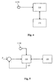
- FIG 4 is a block diagram of one embodiment of a control system according to the principles of the present invention.
- CPU 116 is coupled to power source 120 and irrigation pressure sensor 1130. In this manner, CPU 116 receives pressure information from irrigation pressure sensor 1130.
- CPU 116 also interfaces with power source 120 and controls its operation - thereby controlling the power sent to the hand piece. As previously described, CPU 116 can be any suitable controller.
- the amount of heat generated is a function of the amount of power applied to the hand piece and the amount of irrigation fluid flow through the eye. Friction between the irrigation sleeve and the phacoemulsification needle is the primary source of heat. When the needle rubs against the sleeve, it produces heat.
- the amount of power applied to the hand piece is linearly related to the needle stroke - or the distance the needle travels. The more power applied, the more the needle travels (and the more the needle rubs against the sleeve).
- G(t) G 0 e ⁇ ⁇ t
- G t G 0 e ⁇ ⁇ t
- the coefficients 'G 0 ' and ' ⁇ ' can be determined to best fit the coefficient of friction (between the sleeve and the needle) and experimental data on ⁇ T under various flow and power conditions.
- the calculated thermal value (T) is a function of: the power (P) applied to the hand piece, the fluid flow (F) through the eye, and the friction (Fr) between the needle and the sleeve.
- This calculated thermal value is used to implement a thermal watch algorithm. Since the calculated thermal value provides a good estimate of the actual temperature, a threshold thermal value can be set to trigger the algorithm. In other words, when the calculated thermal value exceeds the threshold thermal value, the algorithm can act to reduce the likelihood of heating (by decreasing power).
- the calculated thermal value is used as an input to control the amount of power provided to the hand piece.
- the actual power applied to the hand piece tracks the inverse of the calculated thermal value when the calculated thermal value exceeds the threshold thermal value. This is more clearly seen with reference to Figures 6-10 below.
- the threshold thermal value (or the value above which the algorithm is executed) can be set by the user of the system, or it can be preset.
- a range of threshold thermal values can be chosen - each of which provides a level of protection against unwanted corneal bums.
- the highest threshold thermal value in the range can be set at a value that provides a small difference (e.g. one degree F) between the temperature at which the cornea burns and the threshold.
- a lower threshold thermal value can be set so that the difference between the temperature at which the cornea bums and the threshold is much greater (10 degrees F or so).
- the algorithm is executed when the calculated thermal value is above the threshold thermal value.
- the algorithm stops executing. In this manner, the algorithm turns on and off as the calculated thermal value exceeds and falls below the threshold thermal value.
- FIG. 5 is a block diagram of another embodiment of a control system according to the principles of the present invention.
- Figure 5 more clearly shows the algorithm in operation.
- CPU 116 calculates the calculated thermal value based on a reading from the irrigation pressure sensor 1130, the power from the power source 120, and the estimated friction.
- CPU 116 acts like a PID controller (and instead of CPU 116, a PID controller or other similar type of controller can be used).
- the inverse of the scaled calculated thermal value is subtracted from the power to reduce the power applied to the hand piece.
- CPU 116 controls the output of power source 120 by decreasing the amount of power output by power source 120 by an amount that is inversely proportional to the calculated thermal value (or by an amount that is inversely proportional to the thermal value in excess of the threshold) - designated by xT - where x can be a scalar or a function.
- the power supplied to the hand piece is decreased in proportion to an amount that is in excess of the threshold thermal value.
- the calculated thermal value falls below the threshold thermal value, normal operation resumes.
- This implementation of the thermal watch algorithm can be set to run automatically during cataract surgery.
- the doctor controls the application of power to the hand piece (generally via a foot pedal).
- the thermal watch algorithm overrides the doctor's control of power.
- the doctor's control of power is resumed.
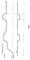
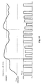
- Figure 6 is a graph depicting an exemplary operation of the thermal management algorithm in continuous mode according to the principles of the present invention.
- the top graph indicates calculated thermal value
- the bottom graph indicates power applied to the hand piece.
- the surgeon can apply continuous power to the hand piece. In this case, the surgeon applies 100% power to the hand piece. However, the surgeon can apply any power level by depressing the foot switch.
- power is applied continuously to the hand piece while the foot pedal is depressed. The degree to which the foot pedal is depressed (or the position of the foot pedal) determines the amount of power or power level applied.
- the thermal watch algorithm overrides the surgeon's control of power.
- the thermal watch algorithm acts to decrease the power in proportion to the temperature rise over the threshold thermal value.
- an incremental temperature increase over the threshold thermal value results in a proportional decrease in the amount of power applied to the hand piece.
- the decrease in power can be smooth as depicted in Figure 6 . In this manner, a smooth decrease in power still results in power being applied smoothly to the cutting tip of the hand piece.
- the calculated thermal value will tend to decrease as well.
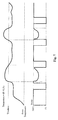
- Figure 7 is a graph depicting an exemplary operation of the thermal management algorithm in pulse mode according to the principles of the present invention.
- the top graph indicates calculated thermal value
- the bottom graph indicates power applied to the hand piece.
- pulse mode a series of fixed width pulses is applied to the hand piece.
- the surgeon controls the amplitude (or power level) of the pulses with the foot switch. In this manner, the position of the footswitch determines the power level of the pulses.
- the calculated thermal value is below the threshold thermal value
- the surgeon can apply any desired power to the hand piece. In this case, the surgeon applies 100% power to the hand piece.
- the thermal watch algorithm overrides the surgeon's control of power.
- the thermal watch algorithm acts to decrease the power in proportion to the temperature rise over the threshold thermal value.
- an incremental temperature increase over the threshold thermal value results in a proportional decrease in the amount of power applied to the hand piece.
- the decrease in power can be smooth as depicted in Figure 7 .
- a smooth decrease in power still results in power being applied smoothly to the cutting tip of the hand piece.
- the thermal watch algorithm operates to decrease the power of any given pulse non-linearly. In this manner, the thermal watch algorithm operates on an individual pulse (or a series of pulses as the case may be).
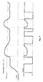
- Figure 8 is a graph depicting an exemplary operation of the thermal management algorithm in pulse mode according to the principles of the present invention.
- the top graph indicates calculated thermal value
- the bottom graph indicates power applied to the hand piece.
- pulse mode a series of fixed width pulses is applied to the hand piece.
- the surgeon controls the amplitude (or power level) of the pulses with the foot switch. In this manner, the position of the footswitch determines the power level of the pulses.
- the calculated thermal value is below the threshold thermal value
- the surgeon can apply any desired power to the hand piece. In this case, the surgeon applies 100% power to the hand piece.
- the thermal watch algorithm overrides the surgeon's control of power.
- the thermal watch algorithm acts to decrease the power in proportion to the temperature rise over the threshold thermal value.
- an incremental temperature increase over the threshold thermal value results in a proportional decrease in the amount of power applied to the hand piece.
- the decrease in power can be incremental as depicted in Figure 8 .
- an incremental decrease in power still results in power being applied to the cutting tip of the hand piece.
- the thermal watch algorithm operates to decrease the power of the next pulse while maintaining a constant pulse level. In this manner, the thermal watch algorithm operates on the next pulse and serves to limit the power level of that next pulse to a constant power level.
- Figure 9 is a graph depicting an exemplary operation of the thermal management algorithm in burst mode according to the principles of the present invention.
- the top graph indicates calculated thermal value
- the bottom graph indicates power applied to the hand piece.
- burst mode a series of pulses is applied to the hand piece. The surgeon controls the off time between pulses with the foot switch. In this manner, the position of the footswitch determines the off time between the pulses.
- the calculated thermal value is below the threshold thermal value
- the surgeon can apply any desired power to the hand piece. In this case, the surgeon applies 100% power to the hand piece.
- the thermal watch algorithm overrides the surgeon's control of power.
- the thermal watch algorithm acts to decrease the power in proportion to the temperature rise over the threshold thermal value.
- an incremental temperature increase over the threshold thermal value results in a proportional decrease in the amount of power applied to the hand piece.
- the decrease in power can be smooth as depicted in Figure 9 .
- a smooth decrease in power still results in power being applied smoothly to the cutting tip of the hand piece.
- the thermal watch algorithm operates to decrease the power of any given pulse non-linearly. In this manner, the thermal watch algorithm operates on an individual pulse (or a series of pulses as the case may be).
- Figure 10 is a graph depicting an exemplary operation of the thermal management algorithm in burst mode according to the principles of the present invention.
- the top graph indicates calculated thermal value
- the bottom graph indicates power applied to the hand piece.
- burst mode a series of pulses is applied to the hand piece. The surgeon controls the off time between pulses with the foot switch. In this manner, the position of the footswitch determines the off time between the pulses.
- the calculated thermal value is below the threshold thermal value
- the surgeon can apply any desired power to the hand piece. In this case, the surgeon applies 100% power to the hand piece.
- the thermal watch algorithm overrides the surgeon's control of power.
- the thermal watch algorithm acts to decrease the power in proportion to the temperature rise over the threshold thermal value.
- an incremental temperature increase over the threshold thermal value results in a proportional decrease in the amount of power applied to the hand piece.
- the decrease in power can be incremental as depicted in Figure 10 .
- an incremental decrease in power still results in power being applied to the cutting tip of the hand piece.
- the thermal watch algorithm operates to decrease the power of the next pulse while maintaining a constant pulse level. In this manner, the thermal watch algorithm operates on the next pulse and serves to limit the power level of that next pulse to a constant power level.
- the power is decreased in proportion to a scalar factor of the temperature increase.
- the power is decreased in proportion to a function of the temperature increase.
- a minimum power level can be set. In this case, power will never fall below the minimum power level thus resulting in a continuous (albeit lower) application of power to the hand piece.
- the rate at which power is decreased can be changed. In this case, the power decrease can be made to be as smooth as desired. A smooth decrease in power results in more effective cutting (as power is applied continuously and not turned off) and better surgeon feel.
- the present invention provides a thermal management algorithm for phacoemulsification surgery.
- the present invention provides a control system that calculates a thermal value, compares the thermal value to a threshold thermal value, and reduces power supplied to the hand piece when the calculated thermal value exceeds the threshold thermal value.
- the present invention is illustrated herein by example, and various modifications may be made by a person of ordinary skill in the art.
Landscapes
- Health & Medical Sciences (AREA)
- Heart & Thoracic Surgery (AREA)
- Life Sciences & Earth Sciences (AREA)
- Animal Behavior & Ethology (AREA)
- Engineering & Computer Science (AREA)
- Ophthalmology & Optometry (AREA)
- Biomedical Technology (AREA)
- Veterinary Medicine (AREA)
- Public Health (AREA)
- Vascular Medicine (AREA)
- General Health & Medical Sciences (AREA)
- Pulmonology (AREA)
- Hematology (AREA)
- Nuclear Medicine, Radiotherapy & Molecular Imaging (AREA)
- Anesthesiology (AREA)
- Surgery (AREA)
- Surgical Instruments (AREA)
- Prostheses (AREA)
Description
- The present invention relates to phacoemulsification surgery and more particularly to a thermal management algorithm in which the amplitude of power applied to a phacoemulsification hand piece is varied in proportion to temperature.
- The human eye functions to provide vision by transmitting light through a clear outer portion called the cornea, and focusing the image by way of a crystalline lens onto a retina. The quality of the focused image depends on many factors including the size and shape of the eye, and the transparency of the cornea and the lens. When age or disease causes the lens to become less transparent, vision deteriorates because of the diminished light which can be transmitted to the retina. This deficiency in the lens of the eye is medically known as a cataract. An accepted treatment for this condition is surgical removal of the lens and replacement of the lens function by an artificial intraocular lens (IOL).
- In the United States, the majority of cataractous lenses are removed by a surgical technique called phacoemulsification. A typical surgical hand piece suitable for phacoemulsification procedures consists of an ultrasonically driven phacoemulsification hand piece, an attached hollow cutting needle surrounded by an irrigating sleeve, and an electronic control console. The hand piece assembly is attached to the control console by an electric cable and flexible tubing. Through the electric cable, the console varies the power level transmitted by the hand piece to the attached cutting needle. The flexible tubing supplies irrigation fluid to the surgical site and draws aspiration fluid from the eye through the hand piece assembly.
- The operative part in a typical hand piece is a centrally located, hollow resonating bar or horn directly attached to a set of piezoelectric crystals. The crystals supply the required ultrasonic vibration needed to drive both the horn and the attached cutting needle during phacoemulsification, and are controlled by the console. The crystal/horn assembly is suspended within the hollow body or shell of the hand piece by flexible mountings. The hand piece body terminates in a reduced diameter portion or nosecone at the body's distal end. Typically, the nosecone is externally threaded to accept the hollow irrigation sleeve, which surrounds most of the length of the cutting needle. Likewise, the horn bore is internally threaded at its distal end to receive the external threads of the cutting tip. The irrigation sleeve also has an internally threaded bore that is screwed onto the external threads of the nosecone. The cutting needle is adjusted so that its tip projects only a predetermined amount past the open end of the irrigating sleeve.
- During the phacoemulsification procedure, the tip of the cutting needle and the end of the irrigation sleeve are inserted into the anterior capsule of the eye through a small incision in the outer tissue of the eye. The surgeon brings the tip of the cutting needle into contact with the lens of the eye, so that the vibrating tip fragments the lens. The resulting fragments are aspirated out of the eye through the interior bore of the cutting needle, along with irrigation solution provided to the eye during the procedure, and into a waste reservoir.
- Throughout the procedure, irrigating fluid is pumped into the eye, passing between the irrigation sleeve and the cutting needle and exiting into the eye at the tip of the irrigation sleeve and/or from one or more ports, or openings, cut into the irrigation sleeve near its end. The irrigating fluid protects the eye tissues from the heat generated by the vibrating of the ultrasonic cutting needle. Furthermore, the irrigating fluid suspends the fragments of the emulsified lens for aspiration from the eye.
- Power is applied to the hand piece to vibrate the cutting needle. In general, the amplitude of needle movement (or vibration) is proportional to the power applied. In conventional phacoemulsification systems, the needle vibrates back and forth producing a longitudinal needle stroke. In improved systems, the needle may be caused to vibrate in a twisting or torsional motion. Regardless of the type of vibration, the magnitude of vibration (or amplitude of needle stroke) varies with applied power.
- One complication that may arise during the procedure is burning of the cornea at the incision site. These corneal bums are caused by heating of the needle (and surrounding sleeve) at the corneal incision. The inventors have found that this heating is dependent on three basic factors: the amount of power applied to the hand piece (which in turn determines the magnitude of needle vibration or amplitude of needle stroke); the amount of fluid flow through the eye (since the fluid carries heat away); and the amount of friction between the needle and the surrounding sleeve at the incision (as can be appreciated, the tighter the fit between the sleeve and the needle, the more friction, and the more heat produced as the needle vibrates).
- In other words, heat is produced at the corneal incision as the cutting needle rubs against the surrounding irrigation sleeve. This heat is normally dissipated by fluid flowing through irrigation sleeve, into the anterior chamber of the eye, and out of the eye through the aspiration lumen. The friction between the cutting needle and the sleeve at the corneal incision site can vary depending on the characteristics of the incision. Generally, a smaller incision (which is desirable from a surgical perspective) can lead to a greater friction force between the needle and the sleeve as the walls of the incision press the sleeve against the needle. In such a case, when the needle is vibrated, heat is produced. If the fluid flowing through the eye is insufficient (or if too much heat is produced), a corneal burn can result. Corneal bums are problematic because they distort the cornea resulting in distorted vision. Since cataract surgery has gravitated toward smaller and smaller incisions, the risk of corneal bums appears to be increasing.
- The relevant state of the art is represented by
WO 2005/092022 (Alcon Inc.) - The present invention is defined in the independent claim 1.
- Preferred embodiments are defined by the claims dependent thereon.
- In one embodiment consistent with the principles of the present invention, the present invention is a control system for managing power supplied to a phacoemulsification hand piece. The control system includes an irrigation pressure sensor, a power source that provides power to the hand piece, and a controller that controls the power source. The controller calculates a thermal value based on the irrigation pressure and a power level and decreases the power level in proportion to the calculated thermal value when the calculated thermal value exceeds a threshold thermal value.
- In another embodiment consistent with the principles of the present invention, the present invention is a control system for managing power supplied to a phacoemulsification hand piece. The control system includes a power source that provides power to the hand piece and a controller that controls the power source. The controller calculates a thermal value based on irrigation fluid flow and a power level and decreases the power level in proportion to the calculated thermal value when the calculated thermal value exceeds a threshold thermal value. Irrigation fluid flow can be calculated from an irrigation pressure.
- It is to be understood that both the foregoing general description and the following detailed description are exemplary and explanatory only and are intended to provide further explanation of the invention as claimed. The following description, as well as the practice of the invention, set forth and suggest additional advantages and purposes of the invention.
- The accompanying drawings, which are incorporated in and constitute a part of this specification, illustrate several embodiments of the invention and together with the description, serve to explain the principles of the invention.
-
Figure 1 is a diagram of the components in the fluid path of a phacoemulsification system. -
Figure 2 is a perspective view of the distal end of a phacoemulsification needle and irrigation sleeve. -
Figure 3 is a diagram of a partial system according to the principles of the present invention. -
Figure 4 is a block diagram of one embodiment of a control system according to the principles of the present invention. -
Figure 5 is a block diagram of another embodiment of a control system according to the principles of the present invention. -
Figure 6 is a graph depicting an exemplary operation of the thermal management algorithm in continuous mode according to the principles of the present invention. -
Figure 7 is a graph depicting an exemplary operation of the thermal management algorithm in pulse mode according to the principles of the present invention. -
Figure 8 is a graph depicting an exemplary operation of the thermal management algorithm in pulse mode according to the principles of the present invention. -
Figure 9 is a graph depicting an exemplary operation of the thermal management algorithm in burst mode according to the principles of the present invention. -
Figure 10 is a graph depicting an exemplary operation of the thermal management algorithm in burst mode according to the principles of the present invention. - Reference is now made in detail to the exemplary embodiments of the invention, examples of which are illustrated in the accompanying drawings. Wherever possible, the same reference numbers are used throughout the drawings to refer to the same or like parts.
- In one embodiment of the present invention,
Figure 1 is a diagram of the components in the fluid path of a phacoemulsification system.Figure 1 depicts the fluid path through theeye 1145 during cataract surgery. The components include an irrigation fluid sourcel 105, anirrigation pressure sensor 1130, anirrigation valve 1135, anirrigation line 1140, ahand piece 1150, anaspiration line 1155, anaspiration pressure sensor 1160, avent valve 1165, apump 1170, areservoir 1175 and adrain bag 1180. Theirrigation line 1140 provides irrigation fluid to theeye 1145 during cataract surgery. Theaspiration line 1155 removes fluid and emulsified lens particles from the eye during cataract surgery. - When irrigation fluid exits
irrigation fluid source 1105, it travels throughirrigation line 1140 and into theeye 1145. Anirrigation pressure sensor 1130 measures the pressure of the irrigation fluid inirrigation line 1140. Anoptional irrigation valve 1135 is also provided for on/off control of irrigation.Irrigation pressure sensor 1130 is implemented by any of a number of commercially available fluid pressure sensors and can be located any where in the irrigation fluid path (any where between theirrigation source 1105 and the eye 1145). - A
hand piece 1150 is placed in theeye 1145 during a phacoemulsification procedure. Thehand piece 1150 has a hollow needle (as seen inFigure 2 ) that is ultrasonically vibrated in the eye to break up the diseased lens. A sleeve located around the needle provides irrigation fluid fromirrigation line 1140. The irrigation fluid passes through the space between the outside of the needle and the inside of the sleeve (as more clearly shown in Figures 12 and 13). Fluid and lens particles are aspirated through the hollow needle. In this manner, the interior passage of the hollow needle is fluidly coupled toaspiration line 1155.Pump 1170 draws the aspirated fluid from theeye 1145. Anaspiration pressure sensor 1160 measures the pressure in the aspiration line. An optional vent valve can be used to vent the vacuum created bypump 1170. The aspirated fluid passes throughreservoir 1175 and intodrain bag 1180. -
Figure 2 is a perspective view of the distal end of a prior art phacoemulsification hand piece. InFigure 2 , aphacoemulsification needle 1210 is surrounded by anirrigation sleeve 1230. Thephacoemulsification needle 1210 has anopen end 1220 through which lens particles are aspirated from the eye during cataract surgery. Theirrigation sleeve 1230 has anoptional opening 1240 through which irrigation fluid flows into the eye. Theneedle 1210 andsleeve 1230 are both inserted into the anterior chamber of the eye during cataract surgery. When power is applied to the hand piece, theneedle 1210 vibrates ultrasonically. Friction between theneedle 1210 and thesleeve 1230 can cause heating to occur - particularly at the incision site. A tight incision presses thesleeve 1230 against theneedle 1210 which can lead to heating and potentially a corneal burn. -
Figure 3 is a diagram of a partial system according to the principles of the present invention. InFigure 3 , irrigation fluid source provides irrigation fluid tohand piece 1150. An irrigation pressure sensor measures the pressure of the irrigation fluid. Apower source 120 provides power tohand piece 1150. As previously described,power source 120 provides ultrasonic power tohand piece 1150 that vibrates the phacoemulsification needle. -
Figure 4 is a block diagram of one embodiment of a control system according to the principles of the present invention. InFigure 4 ,CPU 116 is coupled topower source 120 andirrigation pressure sensor 1130. In this manner,CPU 116 receives pressure information fromirrigation pressure sensor 1130.CPU 116 also interfaces withpower source 120 and controls its operation - thereby controlling the power sent to the hand piece. As previously described,CPU 116 can be any suitable controller. - As previously described, unwanted heating can occur at the incision site when too much power is applied to the hand piece and too little irrigation fluid flows through the eye. Since the irrigation fluid carries heat away, when irrigation fluid flow is decreased (for example, when an occlusion occurs), heating can occur. Generally, the amount of heat generated is a function of the amount of power applied to the hand piece and the amount of irrigation fluid flow through the eye. Friction between the irrigation sleeve and the phacoemulsification needle is the primary source of heat. When the needle rubs against the sleeve, it produces heat. The amount of power applied to the hand piece is linearly related to the needle stroke - or the distance the needle travels. The more power applied, the more the needle travels (and the more the needle rubs against the sleeve).
- Mathematically, if ΔT is the rise in the thermal value, then ΔT = T - T0, (where T0 is the thermal value of the eye and T is the actual thermal value around the needle as a function of time). Suppose that the thermal response to an ultrasonic pulse that happens at time t=0 of the total energy A is given by:


- Emprical studies have found the response function G(t) to be exponential as shown below.

- In this manner, the calculated thermal value (T) is a function of: the power (P) applied to the hand piece, the fluid flow (F) through the eye, and the friction (Fr) between the needle and the sleeve. The fluid flow through the eye is calculated from the irrigation pressure (since the cross section area of the irrigation path is known, the flow through the irrigation line is calculated based on the irrigation fluid pressure as read from the irrigation pressure sensor). Therefore, T = F (P, F, Fr). This calculated thermal value provides a good estimate of the actual temperature experienced at the incision site (where burning is most likely to occur).
- This calculated thermal value is used to implement a thermal watch algorithm. Since the calculated thermal value provides a good estimate of the actual temperature, a threshold thermal value can be set to trigger the algorithm. In other words, when the calculated thermal value exceeds the threshold thermal value, the algorithm can act to reduce the likelihood of heating (by decreasing power).
- As seen in
Figure 4 , theCPU 116 reads the irrigation pressure from theirrigation pressure sensor 1130. SinceCPU 116 controls thepower source 120,CPU 116 also has the value for the power level applied to the hand piece.CPU 116 uses these two values (in conjunction with the coefficient of friction) to calculate a temperature that estimates the actual temperature at the incision site. In this manner,CPU 116 continuously or periodically calculates T = f(P, F, Fr). The calculated thermal value is compared continuously or periodically to a threshold thermal value. When the calculated thermal value exceeds the threshold thermal value, the power to the hand piece is decreased. - In one embodiment of the present invention, the calculated thermal value is used as an input to control the amount of power provided to the hand piece. In this manner, the actual power applied to the hand piece tracks the inverse of the calculated thermal value when the calculated thermal value exceeds the threshold thermal value. This is more clearly seen with reference to
Figures 6-10 below. - As described, the threshold thermal value (or the value above which the algorithm is executed) can be set by the user of the system, or it can be preset. A range of threshold thermal values can be chosen - each of which provides a level of protection against unwanted corneal bums. For example, the highest threshold thermal value in the range can be set at a value that provides a small difference (e.g. one degree F) between the temperature at which the cornea burns and the threshold. A lower threshold thermal value can be set so that the difference between the temperature at which the cornea bums and the threshold is much greater (10 degrees F or so).
- Regardless of the threshold chosen, the algorithm is executed when the calculated thermal value is above the threshold thermal value. When the calculated thermal value falls below the threshold, the algorithm stops executing. In this manner, the algorithm turns on and off as the calculated thermal value exceeds and falls below the threshold thermal value.
-
Figure 5 is a block diagram of another embodiment of a control system according to the principles of the present invention.Figure 5 more clearly shows the algorithm in operation.CPU 116 calculates the calculated thermal value based on a reading from theirrigation pressure sensor 1130, the power from thepower source 120, and the estimated friction. InFigure 5 ,CPU 116 acts like a PID controller (and instead ofCPU 116, a PID controller or other similar type of controller can be used). The inverse of the scaled calculated thermal value is subtracted from the power to reduce the power applied to the hand piece. In this manner,CPU 116 controls the output ofpower source 120 by decreasing the amount of power output bypower source 120 by an amount that is inversely proportional to the calculated thermal value (or by an amount that is inversely proportional to the thermal value in excess of the threshold) - designated by xT - where x can be a scalar or a function. - In this manner, when the calculated thermal value exceeds the threshold thermal value, the power supplied to the hand piece is decreased in proportion to an amount that is in excess of the threshold thermal value. When the calculated thermal value falls below the threshold thermal value, normal operation resumes.
- This implementation of the thermal watch algorithm can be set to run automatically during cataract surgery. During surgery, the doctor controls the application of power to the hand piece (generally via a foot pedal). When the calculated thermal value exceeds the threshold thermal value, the thermal watch algorithm overrides the doctor's control of power. When the calculated thermal value falls below the threshold thermal value, the doctor's control of power is resumed.
-
Figure 6 is a graph depicting an exemplary operation of the thermal management algorithm in continuous mode according to the principles of the present invention. InFigure 6 , the top graph indicates calculated thermal value, and the bottom graph indicates power applied to the hand piece. When the calculated thermal value is below the threshold thermal value, the surgeon can apply continuous power to the hand piece. In this case, the surgeon applies 100% power to the hand piece. However, the surgeon can apply any power level by depressing the foot switch. In continuous mode, power is applied continuously to the hand piece while the foot pedal is depressed. The degree to which the foot pedal is depressed (or the position of the foot pedal) determines the amount of power or power level applied. When the calculated thermal value exceeds the threshold thermal value, the thermal watch algorithm overrides the surgeon's control of power. In this manner, the thermal watch algorithm acts to decrease the power in proportion to the temperature rise over the threshold thermal value. In other words, an incremental temperature increase over the threshold thermal value results in a proportional decrease in the amount of power applied to the hand piece. The decrease in power can be smooth as depicted inFigure 6 . In this manner, a smooth decrease in power still results in power being applied smoothly to the cutting tip of the hand piece. When the power is decreased, the calculated thermal value will tend to decrease as well. When the calculated thermal value falls below the threshold thermal value, the surgeon resumes control of power - in this case, power applied returns to 100%. -
Figure 7 is a graph depicting an exemplary operation of the thermal management algorithm in pulse mode according to the principles of the present invention. InFigure 7 , the top graph indicates calculated thermal value, and the bottom graph indicates power applied to the hand piece. In pulse mode, a series of fixed width pulses is applied to the hand piece. The surgeon controls the amplitude (or power level) of the pulses with the foot switch. In this manner, the position of the footswitch determines the power level of the pulses. When the calculated thermal value is below the threshold thermal value, the surgeon can apply any desired power to the hand piece. In this case, the surgeon applies 100% power to the hand piece. When the calculated thermal value exceeds the threshold thermal value, the thermal watch algorithm overrides the surgeon's control of power. In this manner, the thermal watch algorithm acts to decrease the power in proportion to the temperature rise over the threshold thermal value. In other words, an incremental temperature increase over the threshold thermal value results in a proportional decrease in the amount of power applied to the hand piece. The decrease in power can be smooth as depicted inFigure 7 . In this manner, a smooth decrease in power still results in power being applied smoothly to the cutting tip of the hand piece. When the power is decreased, the calculated thermal value will tend to decrease as well. When the calculated thermal value falls below the threshold thermal value, the surgeon resumes control of power - in this case, power applied returns to 100%. As shown inFigure 7 , the thermal watch algorithm operates to decrease the power of any given pulse non-linearly. In this manner, the thermal watch algorithm operates on an individual pulse (or a series of pulses as the case may be). -
Figure 8 is a graph depicting an exemplary operation of the thermal management algorithm in pulse mode according to the principles of the present invention. InFigure 8 , the top graph indicates calculated thermal value, and the bottom graph indicates power applied to the hand piece. In pulse mode, a series of fixed width pulses is applied to the hand piece. The surgeon controls the amplitude (or power level) of the pulses with the foot switch. In this manner, the position of the footswitch determines the power level of the pulses. When the calculated thermal value is below the threshold thermal value, the surgeon can apply any desired power to the hand piece. In this case, the surgeon applies 100% power to the hand piece. When the calculated thermal value exceeds the threshold thermal value, the thermal watch algorithm overrides the surgeon's control of power. In this manner, the thermal watch algorithm acts to decrease the power in proportion to the temperature rise over the threshold thermal value. In other words, an incremental temperature increase over the threshold thermal value results in a proportional decrease in the amount of power applied to the hand piece. The decrease in power can be incremental as depicted inFigure 8 . In this manner, an incremental decrease in power still results in power being applied to the cutting tip of the hand piece. When the power is decreased, the calculated thermal value will tend to decrease as well. When the calculated thermal value falls below the threshold thermal value, the surgeon resumes control of power - in this case, power applied returns to 100%. As shown inFigure 8 , the thermal watch algorithm operates to decrease the power of the next pulse while maintaining a constant pulse level. In this manner, the thermal watch algorithm operates on the next pulse and serves to limit the power level of that next pulse to a constant power level. -
Figure 9 is a graph depicting an exemplary operation of the thermal management algorithm in burst mode according to the principles of the present invention. InFigure 9 , the top graph indicates calculated thermal value, and the bottom graph indicates power applied to the hand piece. In burst mode, a series of pulses is applied to the hand piece. The surgeon controls the off time between pulses with the foot switch. In this manner, the position of the footswitch determines the off time between the pulses. When the calculated thermal value is below the threshold thermal value, the surgeon can apply any desired power to the hand piece. In this case, the surgeon applies 100% power to the hand piece. When the calculated thermal value exceeds the threshold thermal value, the thermal watch algorithm overrides the surgeon's control of power. In this manner, the thermal watch algorithm acts to decrease the power in proportion to the temperature rise over the threshold thermal value. In other words, an incremental temperature increase over the threshold thermal value results in a proportional decrease in the amount of power applied to the hand piece. The decrease in power can be smooth as depicted inFigure 9 . In this manner, a smooth decrease in power still results in power being applied smoothly to the cutting tip of the hand piece. When the power is decreased, the calculated thermal value will tend to decrease as well. When the calculated thermal value falls below the threshold thermal value, the surgeon resumes control of power - in this case, power applied returns to 100%. As shown inFigure 9 , the thermal watch algorithm operates to decrease the power of any given pulse non-linearly. In this manner, the thermal watch algorithm operates on an individual pulse (or a series of pulses as the case may be). -
Figure 10 is a graph depicting an exemplary operation of the thermal management algorithm in burst mode according to the principles of the present invention. InFigure 10 , the top graph indicates calculated thermal value, and the bottom graph indicates power applied to the hand piece. In burst mode, a series of pulses is applied to the hand piece. The surgeon controls the off time between pulses with the foot switch. In this manner, the position of the footswitch determines the off time between the pulses. When the calculated thermal value is below the threshold thermal value, the surgeon can apply any desired power to the hand piece. In this case, the surgeon applies 100% power to the hand piece. When the calculated thermal value exceeds the threshold thermal value, the thermal watch algorithm overrides the surgeon's control of power. In this manner, the thermal watch algorithm acts to decrease the power in proportion to the temperature rise over the threshold thermal value. In other words, an incremental temperature increase over the threshold thermal value results in a proportional decrease in the amount of power applied to the hand piece. The decrease in power can be incremental as depicted inFigure 10 . In this manner, an incremental decrease in power still results in power being applied to the cutting tip of the hand piece. When the power is decreased, the calculated thermal value will tend to decrease as well. When the calculated thermal value falls below the threshold thermal value, the surgeon resumes control of power - in this case, power applied returns to 100%. As shown inFigure 10 , the thermal watch algorithm operates to decrease the power of the next pulse while maintaining a constant pulse level. In this manner, the thermal watch algorithm operates on the next pulse and serves to limit the power level of that next pulse to a constant power level. - Several variations of the algorithm may also be implemented. In one variation, the power is decreased in proportion to a scalar factor of the temperature increase. In another variation, the power is decreased in proportion to a function of the temperature increase. In another variation, a minimum power level can be set. In this case, power will never fall below the minimum power level thus resulting in a continuous (albeit lower) application of power to the hand piece. In yet another variation, the rate at which power is decreased can be changed. In this case, the power decrease can be made to be as smooth as desired. A smooth decrease in power results in more effective cutting (as power is applied continuously and not turned off) and better surgeon feel.
- From the above, it may be appreciated that the present invention provides a thermal management algorithm for phacoemulsification surgery. The present invention provides a control system that calculates a thermal value, compares the thermal value to a threshold thermal value, and reduces power supplied to the hand piece when the calculated thermal value exceeds the threshold thermal value. The present invention is illustrated herein by example, and various modifications may be made by a person of ordinary skill in the art.
- Other embodiments of the invention will be apparent to those skilled in the art from consideration of the specification and practice of the invention disclosed herein. It is intended that the specification and examples be considered as exemplary only, with a true scope of the invention being indicated by the following claims.
Claims (8)
- A control system for managing power supplied to a phacoemulsification hand piece (1150), the control system comprising:a power source (120) for providing ultrasonic power to the hand piece; anda controller (116) for controlling the power source;characterized in that the controller is configured to use a series of thermal values calculated over a period of time, each thermal value in the series of thermal values calculated from an irrigation pressure as measured by an irrigation pressure sensor (1130) or an irrigation fluid flow as calculated from the irrigation pressure, and a series of power levels over the period of time, to decrease the ultrasonic power provided to the hand piece in proportion to the series of calculated thermal values when one or more of the calculated thermal values in the series of calculated thermal values exceeds a threshold thermal value, such that the ultrasonic power amplitude provided to the hand piece over time is proportionally reduced by the amount the calculated thermal value exceeds the threshold thermal value at a given point in time.
- The control system of claim 1, wherein the series of calculated thermal value is provided as a feedback input to the controller (116).
- The control system of claim 1, wherein the controller (116) is configured to decrease the power level at a smooth rate.
- The control system of claim 1, wherein the thermal value is further calculated from a friction coefficient that represents friction between an irrigation sleeve (1230) and a phacoemulsification needle (1210) of the phacoemulsification handpiece, in addition to the irrigation pressure or irrigation fluid flow, and the power level.
- The control system of claim 1, wherein when the controller (116) decreases the power level in proportion to the calculated thermal value, the controller is configured to override surgeon control of the power source (120).
- The control system of claim 1, wherein when the controller (116) decreases the power level in proportion to the calculated thermal value, the controller is configured to not decrease the power level to zero.
- The control system of claim 1, wherein the power source provides pulsed power to the hand piece and when the controller decreases the power level in proportion to the calculated thermal value, the controller is configured to decrease the amplitude of a pulse.
- The control system of claim 6, wherein surgeon control of the power source (120) is resumed when the calculated thermal value is less than the threshold thermal value.
Applications Claiming Priority (2)
| Application Number | Priority Date | Filing Date | Title |
|---|---|---|---|
| US12/634,283 US8070711B2 (en) | 2009-12-09 | 2009-12-09 | Thermal management algorithm for phacoemulsification system |
| PCT/US2010/058692 WO2011071744A1 (en) | 2009-12-09 | 2010-12-02 | Thermal management algorithm for phacoemulsification system |
Publications (2)
| Publication Number | Publication Date |
|---|---|
| EP2509550A1 EP2509550A1 (en) | 2012-10-17 |
| EP2509550B1 true EP2509550B1 (en) | 2016-09-21 |
Family
ID=43598452
Family Applications (1)
| Application Number | Title | Priority Date | Filing Date |
|---|---|---|---|
| EP10788463.7A Active EP2509550B1 (en) | 2009-12-09 | 2010-12-02 | Thermal management algorithm for phacoemulsification system |
Country Status (8)
| Country | Link |
|---|---|
| US (1) | US8070711B2 (en) |
| EP (1) | EP2509550B1 (en) |
| JP (1) | JP5767241B2 (en) |
| CN (1) | CN102652005B (en) |
| AU (1) | AU2010328494B2 (en) |
| CA (1) | CA2781141C (en) |
| ES (1) | ES2606210T3 (en) |
| WO (1) | WO2011071744A1 (en) |
Families Citing this family (153)
| Publication number | Priority date | Publication date | Assignee | Title |
|---|---|---|---|---|
| US11229472B2 (en) | 2001-06-12 | 2022-01-25 | Cilag Gmbh International | Modular battery powered handheld surgical instrument with multiple magnetic position sensors |
| US8182501B2 (en) | 2004-02-27 | 2012-05-22 | Ethicon Endo-Surgery, Inc. | Ultrasonic surgical shears and method for sealing a blood vessel using same |
| JP5009159B2 (en) | 2004-10-08 | 2012-08-22 | エシコン・エンド−サージェリィ・インコーポレイテッド | Ultrasonic surgical instrument |
| US20070191713A1 (en) | 2005-10-14 | 2007-08-16 | Eichmann Stephen E | Ultrasonic device for cutting and coagulating |
| US7621930B2 (en) | 2006-01-20 | 2009-11-24 | Ethicon Endo-Surgery, Inc. | Ultrasound medical instrument having a medical ultrasonic blade |
| US8142461B2 (en) | 2007-03-22 | 2012-03-27 | Ethicon Endo-Surgery, Inc. | Surgical instruments |
| US8911460B2 (en) | 2007-03-22 | 2014-12-16 | Ethicon Endo-Surgery, Inc. | Ultrasonic surgical instruments |
| US8057498B2 (en) | 2007-11-30 | 2011-11-15 | Ethicon Endo-Surgery, Inc. | Ultrasonic surgical instrument blades |
| US8226675B2 (en) | 2007-03-22 | 2012-07-24 | Ethicon Endo-Surgery, Inc. | Surgical instruments |
| US8523889B2 (en) | 2007-07-27 | 2013-09-03 | Ethicon Endo-Surgery, Inc. | Ultrasonic end effectors with increased active length |
| US8882791B2 (en) | 2007-07-27 | 2014-11-11 | Ethicon Endo-Surgery, Inc. | Ultrasonic surgical instruments |
| US8808319B2 (en) | 2007-07-27 | 2014-08-19 | Ethicon Endo-Surgery, Inc. | Surgical instruments |
| US8512365B2 (en) | 2007-07-31 | 2013-08-20 | Ethicon Endo-Surgery, Inc. | Surgical instruments |
| US8430898B2 (en) | 2007-07-31 | 2013-04-30 | Ethicon Endo-Surgery, Inc. | Ultrasonic surgical instruments |
| US9044261B2 (en) | 2007-07-31 | 2015-06-02 | Ethicon Endo-Surgery, Inc. | Temperature controlled ultrasonic surgical instruments |
| CN101883531B (en) | 2007-10-05 | 2014-07-02 | 伊西康内外科公司 | Ergonomic surgical instruments |
| US10010339B2 (en) | 2007-11-30 | 2018-07-03 | Ethicon Llc | Ultrasonic surgical blades |
| CN102046103A (en) * | 2008-02-20 | 2011-05-04 | 梅约医学教育与研究基金会 | Systems, devices and methods for accessing body tissue |
| US20110118601A1 (en) * | 2008-02-20 | 2011-05-19 | Mayo Foundation For Medical Education And Research Nonprofit Corporation | Ultrasound Guided Systems and Methods |
| US9089360B2 (en) | 2008-08-06 | 2015-07-28 | Ethicon Endo-Surgery, Inc. | Devices and techniques for cutting and coagulating tissue |
| US9700339B2 (en) | 2009-05-20 | 2017-07-11 | Ethicon Endo-Surgery, Inc. | Coupling arrangements and methods for attaching tools to ultrasonic surgical instruments |
| US8344596B2 (en) | 2009-06-24 | 2013-01-01 | Ethicon Endo-Surgery, Inc. | Transducer arrangements for ultrasonic surgical instruments |
| US8663220B2 (en) | 2009-07-15 | 2014-03-04 | Ethicon Endo-Surgery, Inc. | Ultrasonic surgical instruments |
| US10441345B2 (en) | 2009-10-09 | 2019-10-15 | Ethicon Llc | Surgical generator for ultrasonic and electrosurgical devices |
| US9168054B2 (en) | 2009-10-09 | 2015-10-27 | Ethicon Endo-Surgery, Inc. | Surgical generator for ultrasonic and electrosurgical devices |
| US9060775B2 (en) | 2009-10-09 | 2015-06-23 | Ethicon Endo-Surgery, Inc. | Surgical generator for ultrasonic and electrosurgical devices |
| USRE47996E1 (en) | 2009-10-09 | 2020-05-19 | Ethicon Llc | Surgical generator for ultrasonic and electrosurgical devices |
| US11090104B2 (en) | 2009-10-09 | 2021-08-17 | Cilag Gmbh International | Surgical generator for ultrasonic and electrosurgical devices |
| US9795404B2 (en) | 2009-12-31 | 2017-10-24 | Tenex Health, Inc. | System and method for minimally invasive ultrasonic musculoskeletal tissue treatment |
| US8579928B2 (en) | 2010-02-11 | 2013-11-12 | Ethicon Endo-Surgery, Inc. | Outer sheath and blade arrangements for ultrasonic surgical instruments |
| US8486096B2 (en) | 2010-02-11 | 2013-07-16 | Ethicon Endo-Surgery, Inc. | Dual purpose surgical instrument for cutting and coagulating tissue |
| US8469981B2 (en) | 2010-02-11 | 2013-06-25 | Ethicon Endo-Surgery, Inc. | Rotatable cutting implement arrangements for ultrasonic surgical instruments |
| US8961547B2 (en) | 2010-02-11 | 2015-02-24 | Ethicon Endo-Surgery, Inc. | Ultrasonic surgical instruments with moving cutting implement |
| US8951272B2 (en) | 2010-02-11 | 2015-02-10 | Ethicon Endo-Surgery, Inc. | Seal arrangements for ultrasonically powered surgical instruments |
| GB2480498A (en) | 2010-05-21 | 2011-11-23 | Ethicon Endo Surgery Inc | Medical device comprising RF circuitry |
| US8795327B2 (en) | 2010-07-22 | 2014-08-05 | Ethicon Endo-Surgery, Inc. | Electrosurgical instrument with separate closure and cutting members |
| US9192431B2 (en) | 2010-07-23 | 2015-11-24 | Ethicon Endo-Surgery, Inc. | Electrosurgical cutting and sealing instrument |
| US9259265B2 (en) | 2011-07-22 | 2016-02-16 | Ethicon Endo-Surgery, Llc | Surgical instruments for tensioning tissue |
| WO2013119545A1 (en) | 2012-02-10 | 2013-08-15 | Ethicon-Endo Surgery, Inc. | Robotically controlled surgical instrument |
| US10213533B2 (en) * | 2012-03-05 | 2019-02-26 | Keith A. Walter | Medical tools with aspiration tips suitable for cataract surgeries and related methods |
| US9226766B2 (en) | 2012-04-09 | 2016-01-05 | Ethicon Endo-Surgery, Inc. | Serial communication protocol for medical device |
| US9241731B2 (en) | 2012-04-09 | 2016-01-26 | Ethicon Endo-Surgery, Inc. | Rotatable electrical connection for ultrasonic surgical instruments |
| US9724118B2 (en) * | 2012-04-09 | 2017-08-08 | Ethicon Endo-Surgery, Llc | Techniques for cutting and coagulating tissue for ultrasonic surgical instruments |
| US9439668B2 (en) | 2012-04-09 | 2016-09-13 | Ethicon Endo-Surgery, Llc | Switch arrangements for ultrasonic surgical instruments |
| US9237921B2 (en) | 2012-04-09 | 2016-01-19 | Ethicon Endo-Surgery, Inc. | Devices and techniques for cutting and coagulating tissue |
| US20130289469A1 (en) * | 2012-04-26 | 2013-10-31 | Karen T. Hong | Infusion Sleeve With Motion Reduction Profile |
| US10220186B2 (en) * | 2012-05-23 | 2019-03-05 | Becton, Dickinson And Company | Collapse-resistant swellable catheter |
| US11406415B2 (en) | 2012-06-11 | 2022-08-09 | Tenex Health, Inc. | Systems and methods for tissue treatment |
| US9149291B2 (en) | 2012-06-11 | 2015-10-06 | Tenex Health, Inc. | Systems and methods for tissue treatment |
| US20140005705A1 (en) | 2012-06-29 | 2014-01-02 | Ethicon Endo-Surgery, Inc. | Surgical instruments with articulating shafts |
| US9820768B2 (en) | 2012-06-29 | 2017-11-21 | Ethicon Llc | Ultrasonic surgical instruments with control mechanisms |
| US9393037B2 (en) | 2012-06-29 | 2016-07-19 | Ethicon Endo-Surgery, Llc | Surgical instruments with articulating shafts |
| US9198714B2 (en) | 2012-06-29 | 2015-12-01 | Ethicon Endo-Surgery, Inc. | Haptic feedback devices for surgical robot |
| US9326788B2 (en) | 2012-06-29 | 2016-05-03 | Ethicon Endo-Surgery, Llc | Lockout mechanism for use with robotic electrosurgical device |
| US9408622B2 (en) | 2012-06-29 | 2016-08-09 | Ethicon Endo-Surgery, Llc | Surgical instruments with articulating shafts |
| US9351754B2 (en) | 2012-06-29 | 2016-05-31 | Ethicon Endo-Surgery, Llc | Ultrasonic surgical instruments with distally positioned jaw assemblies |
| US9283045B2 (en) | 2012-06-29 | 2016-03-15 | Ethicon Endo-Surgery, Llc | Surgical instruments with fluid management system |
| US20140005702A1 (en) | 2012-06-29 | 2014-01-02 | Ethicon Endo-Surgery, Inc. | Ultrasonic surgical instruments with distally positioned transducers |
| US9226767B2 (en) | 2012-06-29 | 2016-01-05 | Ethicon Endo-Surgery, Inc. | Closed feedback control for electrosurgical device |
| NL2009424C2 (en) | 2012-09-06 | 2014-03-10 | D O R C Dutch Ophthalmic Res Ct International B V | Irrigation/aspiration system, cartridge, pump unit, surgical machine, method for controlling. |
| WO2014052181A1 (en) | 2012-09-28 | 2014-04-03 | Ethicon Endo-Surgery, Inc. | Multi-function bi-polar forceps |
| US9095367B2 (en) | 2012-10-22 | 2015-08-04 | Ethicon Endo-Surgery, Inc. | Flexible harmonic waveguides/blades for surgical instruments |
| US10201365B2 (en) | 2012-10-22 | 2019-02-12 | Ethicon Llc | Surgeon feedback sensing and display methods |
| US20140135804A1 (en) | 2012-11-15 | 2014-05-15 | Ethicon Endo-Surgery, Inc. | Ultrasonic and electrosurgical devices |
| US10226273B2 (en) | 2013-03-14 | 2019-03-12 | Ethicon Llc | Mechanical fasteners for use with surgical energy devices |
| US9241728B2 (en) | 2013-03-15 | 2016-01-26 | Ethicon Endo-Surgery, Inc. | Surgical instrument with multiple clamping mechanisms |
| US9814514B2 (en) | 2013-09-13 | 2017-11-14 | Ethicon Llc | Electrosurgical (RF) medical instruments for cutting and coagulating tissue |
| US9265926B2 (en) | 2013-11-08 | 2016-02-23 | Ethicon Endo-Surgery, Llc | Electrosurgical devices |
| GB2521228A (en) | 2013-12-16 | 2015-06-17 | Ethicon Endo Surgery Inc | Medical device |
| GB2521229A (en) | 2013-12-16 | 2015-06-17 | Ethicon Endo Surgery Inc | Medical device |
| US9795436B2 (en) | 2014-01-07 | 2017-10-24 | Ethicon Llc | Harvesting energy from a surgical generator |
| US9554854B2 (en) | 2014-03-18 | 2017-01-31 | Ethicon Endo-Surgery, Llc | Detecting short circuits in electrosurgical medical devices |
| US10092310B2 (en) | 2014-03-27 | 2018-10-09 | Ethicon Llc | Electrosurgical devices |
| US10463421B2 (en) | 2014-03-27 | 2019-11-05 | Ethicon Llc | Two stage trigger, clamp and cut bipolar vessel sealer |
| US9737355B2 (en) | 2014-03-31 | 2017-08-22 | Ethicon Llc | Controlling impedance rise in electrosurgical medical devices |
| US9913680B2 (en) | 2014-04-15 | 2018-03-13 | Ethicon Llc | Software algorithms for electrosurgical instruments |
| US10285724B2 (en) | 2014-07-31 | 2019-05-14 | Ethicon Llc | Actuation mechanisms and load adjustment assemblies for surgical instruments |
| US9962181B2 (en) | 2014-09-02 | 2018-05-08 | Tenex Health, Inc. | Subcutaneous wound debridement |
| US10639092B2 (en) | 2014-12-08 | 2020-05-05 | Ethicon Llc | Electrode configurations for surgical instruments |
| US10245095B2 (en) | 2015-02-06 | 2019-04-02 | Ethicon Llc | Electrosurgical instrument with rotation and articulation mechanisms |
| US10342602B2 (en) | 2015-03-17 | 2019-07-09 | Ethicon Llc | Managing tissue treatment |
| US10321950B2 (en) | 2015-03-17 | 2019-06-18 | Ethicon Llc | Managing tissue treatment |
| US10595929B2 (en) | 2015-03-24 | 2020-03-24 | Ethicon Llc | Surgical instruments with firing system overload protection mechanisms |
| US9763689B2 (en) | 2015-05-12 | 2017-09-19 | Tenex Health, Inc. | Elongated needles for ultrasonic applications |
| US10034684B2 (en) | 2015-06-15 | 2018-07-31 | Ethicon Llc | Apparatus and method for dissecting and coagulating tissue |
| US11020140B2 (en) | 2015-06-17 | 2021-06-01 | Cilag Gmbh International | Ultrasonic surgical blade for use with ultrasonic surgical instruments |
| US10765470B2 (en) | 2015-06-30 | 2020-09-08 | Ethicon Llc | Surgical system with user adaptable techniques employing simultaneous energy modalities based on tissue parameters |
| US10898256B2 (en) | 2015-06-30 | 2021-01-26 | Ethicon Llc | Surgical system with user adaptable techniques based on tissue impedance |
| US10034704B2 (en) | 2015-06-30 | 2018-07-31 | Ethicon Llc | Surgical instrument with user adaptable algorithms |
| US10357303B2 (en) | 2015-06-30 | 2019-07-23 | Ethicon Llc | Translatable outer tube for sealing using shielded lap chole dissector |
| US11129669B2 (en) | 2015-06-30 | 2021-09-28 | Cilag Gmbh International | Surgical system with user adaptable techniques based on tissue type |
| US11051873B2 (en) | 2015-06-30 | 2021-07-06 | Cilag Gmbh International | Surgical system with user adaptable techniques employing multiple energy modalities based on tissue parameters |
| US10154852B2 (en) | 2015-07-01 | 2018-12-18 | Ethicon Llc | Ultrasonic surgical blade with improved cutting and coagulation features |
| US20170086909A1 (en) | 2015-09-30 | 2017-03-30 | Ethicon Endo-Surgery, Llc | Frequency agile generator for a surgical instrument |
| US10595930B2 (en) | 2015-10-16 | 2020-03-24 | Ethicon Llc | Electrode wiping surgical device |
| US10179022B2 (en) | 2015-12-30 | 2019-01-15 | Ethicon Llc | Jaw position impedance limiter for electrosurgical instrument |
| US10575892B2 (en) | 2015-12-31 | 2020-03-03 | Ethicon Llc | Adapter for electrical surgical instruments |
| US11229471B2 (en) | 2016-01-15 | 2022-01-25 | Cilag Gmbh International | Modular battery powered handheld surgical instrument with selective application of energy based on tissue characterization |
| US10716615B2 (en) | 2016-01-15 | 2020-07-21 | Ethicon Llc | Modular battery powered handheld surgical instrument with curved end effectors having asymmetric engagement between jaw and blade |
| US11134978B2 (en) | 2016-01-15 | 2021-10-05 | Cilag Gmbh International | Modular battery powered handheld surgical instrument with self-diagnosing control switches for reusable handle assembly |
| US12193698B2 (en) | 2016-01-15 | 2025-01-14 | Cilag Gmbh International | Method for self-diagnosing operation of a control switch in a surgical instrument system |
| US11129670B2 (en) | 2016-01-15 | 2021-09-28 | Cilag Gmbh International | Modular battery powered handheld surgical instrument with selective application of energy based on button displacement, intensity, or local tissue characterization |
| US20170215897A1 (en) * | 2016-01-28 | 2017-08-03 | Gyrus Acmi, Inc., D.B.A. Olympus Surgical Technologies America | Apparatus for Stone Fragments Removal |
| US10624785B2 (en) | 2016-01-30 | 2020-04-21 | Carl Zeiss Meditec Cataract Technology Inc. | Devices and methods for ocular surgery |
| US10555769B2 (en) | 2016-02-22 | 2020-02-11 | Ethicon Llc | Flexible circuits for electrosurgical instrument |
| US10485607B2 (en) | 2016-04-29 | 2019-11-26 | Ethicon Llc | Jaw structure with distal closure for electrosurgical instruments |
| US10702329B2 (en) | 2016-04-29 | 2020-07-07 | Ethicon Llc | Jaw structure with distal post for electrosurgical instruments |
| US10646269B2 (en) | 2016-04-29 | 2020-05-12 | Ethicon Llc | Non-linear jaw gap for electrosurgical instruments |
| US10456193B2 (en) | 2016-05-03 | 2019-10-29 | Ethicon Llc | Medical device with a bilateral jaw configuration for nerve stimulation |
| US11432961B2 (en) * | 2016-05-17 | 2022-09-06 | Alcon, Inc. | Automated viscous fluid control in vitreoretinal surgery |
| US10245064B2 (en) | 2016-07-12 | 2019-04-02 | Ethicon Llc | Ultrasonic surgical instrument with piezoelectric central lumen transducer |
| US10893883B2 (en) | 2016-07-13 | 2021-01-19 | Ethicon Llc | Ultrasonic assembly for use with ultrasonic surgical instruments |
| US10842522B2 (en) | 2016-07-15 | 2020-11-24 | Ethicon Llc | Ultrasonic surgical instruments having offset blades |
| US10376305B2 (en) | 2016-08-05 | 2019-08-13 | Ethicon Llc | Methods and systems for advanced harmonic energy |
| US10285723B2 (en) | 2016-08-09 | 2019-05-14 | Ethicon Llc | Ultrasonic surgical blade with improved heel portion |
| USD847990S1 (en) | 2016-08-16 | 2019-05-07 | Ethicon Llc | Surgical instrument |
| US10828056B2 (en) | 2016-08-25 | 2020-11-10 | Ethicon Llc | Ultrasonic transducer to waveguide acoustic coupling, connections, and configurations |
| US10952759B2 (en) | 2016-08-25 | 2021-03-23 | Ethicon Llc | Tissue loading of a surgical instrument |
| US10603064B2 (en) | 2016-11-28 | 2020-03-31 | Ethicon Llc | Ultrasonic transducer |
| US11266430B2 (en) | 2016-11-29 | 2022-03-08 | Cilag Gmbh International | End effector control and calibration |
| US11278450B2 (en) | 2017-05-04 | 2022-03-22 | Carl Zeiss Meditec Cataract Technology Inc. | Devices and methods for ocular surgery |
| US10820920B2 (en) | 2017-07-05 | 2020-11-03 | Ethicon Llc | Reusable ultrasonic medical devices and methods of their use |
| CN112702982B (en) | 2018-06-05 | 2023-12-19 | 卡尔蔡司白内障医疗技术公司 | Ophthalmic microsurgery tools, systems and methods of use |
| EP3917468B1 (en) | 2019-02-01 | 2023-11-15 | Carl Zeiss Meditec Cataract Technology Inc. | Ophthalmic cutting instruments having integrated aspiration pump |
| EP3968912B1 (en) | 2019-05-17 | 2026-05-06 | Carl Zeiss Meditec Cataract Technology Inc. | Ophthalmic cutting instruments having integrated aspiration pump |
| WO2020247165A2 (en) | 2019-06-07 | 2020-12-10 | Carl Zeiss Meditec Cataract Technology Inc. | Multi-stage trigger for ophthalmology cutting tool |
| US11944366B2 (en) | 2019-12-30 | 2024-04-02 | Cilag Gmbh International | Asymmetric segmented ultrasonic support pad for cooperative engagement with a movable RF electrode |
| US11950797B2 (en) | 2019-12-30 | 2024-04-09 | Cilag Gmbh International | Deflectable electrode with higher distal bias relative to proximal bias |
| US11937863B2 (en) | 2019-12-30 | 2024-03-26 | Cilag Gmbh International | Deflectable electrode with variable compression bias along the length of the deflectable electrode |
| US12023086B2 (en) | 2019-12-30 | 2024-07-02 | Cilag Gmbh International | Electrosurgical instrument for delivering blended energy modalities to tissue |
| US11779329B2 (en) | 2019-12-30 | 2023-10-10 | Cilag Gmbh International | Surgical instrument comprising a flex circuit including a sensor system |
| US11986234B2 (en) | 2019-12-30 | 2024-05-21 | Cilag Gmbh International | Surgical system communication pathways |
| US11779387B2 (en) | 2019-12-30 | 2023-10-10 | Cilag Gmbh International | Clamp arm jaw to minimize tissue sticking and improve tissue control |
| US12064109B2 (en) | 2019-12-30 | 2024-08-20 | Cilag Gmbh International | Surgical instrument comprising a feedback control circuit |
| US20210196361A1 (en) | 2019-12-30 | 2021-07-01 | Ethicon Llc | Electrosurgical instrument with monopolar and bipolar energy capabilities |
| US12336747B2 (en) | 2019-12-30 | 2025-06-24 | Cilag Gmbh International | Method of operating a combination ultrasonic / bipolar RF surgical device with a combination energy modality end-effector |
| US11452525B2 (en) | 2019-12-30 | 2022-09-27 | Cilag Gmbh International | Surgical instrument comprising an adjustment system |
| US12349961B2 (en) | 2019-12-30 | 2025-07-08 | Cilag Gmbh International | Electrosurgical instrument with electrodes operable in bipolar and monopolar modes |
| US11786291B2 (en) | 2019-12-30 | 2023-10-17 | Cilag Gmbh International | Deflectable support of RF energy electrode with respect to opposing ultrasonic blade |
| US12053224B2 (en) | 2019-12-30 | 2024-08-06 | Cilag Gmbh International | Variation in electrode parameters and deflectable electrode to modify energy density and tissue interaction |
| US12262937B2 (en) | 2019-12-30 | 2025-04-01 | Cilag Gmbh International | User interface for surgical instrument with combination energy modality end-effector |
| US12076006B2 (en) | 2019-12-30 | 2024-09-03 | Cilag Gmbh International | Surgical instrument comprising an orientation detection system |
| US12343063B2 (en) | 2019-12-30 | 2025-07-01 | Cilag Gmbh International | Multi-layer clamp arm pad for enhanced versatility and performance of a surgical device |
| US12082808B2 (en) | 2019-12-30 | 2024-09-10 | Cilag Gmbh International | Surgical instrument comprising a control system responsive to software configurations |
| US11707318B2 (en) | 2019-12-30 | 2023-07-25 | Cilag Gmbh International | Surgical instrument with jaw alignment features |
| US12114912B2 (en) | 2019-12-30 | 2024-10-15 | Cilag Gmbh International | Non-biased deflectable electrode to minimize contact between ultrasonic blade and electrode |
| US11986201B2 (en) | 2019-12-30 | 2024-05-21 | Cilag Gmbh International | Method for operating a surgical instrument |
| US11696776B2 (en) | 2019-12-30 | 2023-07-11 | Cilag Gmbh International | Articulatable surgical instrument |
| US20210196357A1 (en) | 2019-12-30 | 2021-07-01 | Ethicon Llc | Electrosurgical instrument with asynchronous energizing electrodes |
| US11812957B2 (en) | 2019-12-30 | 2023-11-14 | Cilag Gmbh International | Surgical instrument comprising a signal interference resolution system |
| US11911063B2 (en) | 2019-12-30 | 2024-02-27 | Cilag Gmbh International | Techniques for detecting ultrasonic blade to electrode contact and reducing power to ultrasonic blade |
| US11660089B2 (en) | 2019-12-30 | 2023-05-30 | Cilag Gmbh International | Surgical instrument comprising a sensing system |
| US20250114083A1 (en) * | 2023-10-09 | 2025-04-10 | Alcon Inc. | Control system for ultrasonic hand piece |
Family Cites Families (121)
| Publication number | Priority date | Publication date | Assignee | Title |
|---|---|---|---|---|
| US3526219A (en) * | 1967-07-21 | 1970-09-01 | Ultrasonic Systems | Method and apparatus for ultrasonically removing tissue from a biological organism |
| NL145136C (en) * | 1967-07-25 | 1900-01-01 | ||
| US3601126A (en) * | 1969-01-08 | 1971-08-24 | Electro Medical Systems Inc | High frequency electrosurgical apparatus |
| US3693613A (en) * | 1970-12-09 | 1972-09-26 | Cavitron Corp | Surgical handpiece and flow control system for use therewith |
| US3812855A (en) * | 1971-12-15 | 1974-05-28 | Surgical Design Corp | System for controlling fluid and suction pressure |
| US3812858A (en) * | 1972-10-24 | 1974-05-28 | Sybron Corp | Dental electrosurgical unit |
| US3952732A (en) * | 1972-12-26 | 1976-04-27 | Shock John P | Ultrasonic cataract removal method and apparatus |
| US3857387A (en) | 1972-12-26 | 1974-12-31 | Ultrasonic Systems | Ultrasonic cataract removal method and apparatus |
| US3942519A (en) * | 1972-12-26 | 1976-03-09 | Ultrasonic Systems, Inc. | Method of ultrasonic cryogenic cataract removal |
| US3902495A (en) * | 1974-01-28 | 1975-09-02 | Cavitron Corp | Flow control system |
| US3956826A (en) * | 1974-03-19 | 1976-05-18 | Cavitron Corporation | Ultrasonic device and method |
| US3930505A (en) * | 1974-06-24 | 1976-01-06 | Hydro Pulse Corporation | Surgical apparatus for removal of tissue |
| US4024467A (en) * | 1974-07-15 | 1977-05-17 | Sybron Corporation | Method for controlling power during electrosurgery |
| US4024866A (en) * | 1974-12-02 | 1977-05-24 | Hydro Pulse Corporation | Surgical apparatus for removal of tissue |
| US3964487A (en) * | 1974-12-09 | 1976-06-22 | The Birtcher Corporation | Uncomplicated load-adapting electrosurgical cutting generator |
| DE2504280C3 (en) * | 1975-02-01 | 1980-08-28 | Hans Heinrich Prof. Dr. 8035 Gauting Meinke | Device for cutting and / or coagulating human tissue with high frequency current |
| US3990452A (en) | 1975-06-13 | 1976-11-09 | Fibra-Sonics, Inc. | Medical machine for performing surgery and treating using ultrasonic energy |
| US4126137A (en) | 1977-01-21 | 1978-11-21 | Minnesota Mining And Manufacturing Company | Electrosurgical unit |
| US4184510A (en) * | 1977-03-15 | 1980-01-22 | Fibra-Sonics, Inc. | Valued device for controlling vacuum in surgery |
| US4180074A (en) * | 1977-03-15 | 1979-12-25 | Fibra-Sonics, Inc. | Device and method for applying precise irrigation, aspiration, medication, ultrasonic power and dwell time to biotissue for surgery and treatment |
| US4168707A (en) * | 1977-06-13 | 1979-09-25 | Douvas Nicholas G | Control apparatus for microsurgical instruments |
| DE2741107A1 (en) * | 1977-09-13 | 1979-03-29 | Heldt Gert Dipl Ing Dr | PROCEDURE FOR RELEASING INTERESTED COMPONENTS |
| US4223676A (en) * | 1977-12-19 | 1980-09-23 | Cavitron Corporation | Ultrasonic aspirator |
| US4246902A (en) * | 1978-03-10 | 1981-01-27 | Miguel Martinez | Surgical cutting instrument |
| US4493694A (en) * | 1980-10-17 | 1985-01-15 | Cooper Lasersonics, Inc. | Surgical pre-aspirator |
| US4417578A (en) | 1981-03-20 | 1983-11-29 | Surgical Design | Ultrasonic transducer with energy shielding |
| US4406284B1 (en) * | 1981-03-20 | 1997-11-18 | Surgical Design Corp | Ultrasonic handpiece design |
| US4496342A (en) * | 1981-03-20 | 1985-01-29 | Surgical Design Corporation | Surge prevention system for an ophthalmic instrument |
| US4590935A (en) * | 1981-11-02 | 1986-05-27 | Optikon Oftalmologia, S.P.A. | Control system for intraocular surgical device |
| US4504264A (en) * | 1982-09-24 | 1985-03-12 | Kelman Charles D | Apparatus for and method of removal of material using ultrasonic vibraton |
| DE3378719D1 (en) * | 1983-05-24 | 1989-01-26 | Chang Sien Shih | Electro-surgical unit control apparatus |
| US4508532A (en) * | 1983-09-09 | 1985-04-02 | Ninetronix, Inc. | Ophthalmic aspirator/irrigator and cystotome |
| US4658819A (en) * | 1983-09-13 | 1987-04-21 | Valleylab, Inc. | Electrosurgical generator |
| US4515583A (en) | 1983-10-17 | 1985-05-07 | Coopervision, Inc. | Operative elliptical probe for ultrasonic surgical instrument and method of its use |
| US4609368A (en) * | 1984-08-22 | 1986-09-02 | Dotson Robert S Jun | Pneumatic ultrasonic surgical handpiece |
| US4589415A (en) * | 1984-08-31 | 1986-05-20 | Haaga John R | Method and system for fragmenting kidney stones |
| US4739759A (en) * | 1985-02-26 | 1988-04-26 | Concept, Inc. | Microprocessor controlled electrosurgical generator |
| US4750488A (en) * | 1986-05-19 | 1988-06-14 | Sonomed Technology, Inc. | Vibration apparatus preferably for endoscopic ultrasonic aspirator |
| US4922902A (en) * | 1986-05-19 | 1990-05-08 | Valleylab, Inc. | Method for removing cellular material with endoscopic ultrasonic aspirator |
| US4770654A (en) * | 1985-09-26 | 1988-09-13 | Alcon Laboratories Inc. | Multimedia apparatus for driving powered surgical instruments |
| US4712544A (en) | 1986-02-12 | 1987-12-15 | Castle Company | Electrosurgical generator |
| US4989588A (en) * | 1986-03-10 | 1991-02-05 | Olympus Optical Co., Ltd. | Medical treatment device utilizing ultrasonic wave |
| US4827911A (en) * | 1986-04-02 | 1989-05-09 | Cooper Lasersonics, Inc. | Method and apparatus for ultrasonic surgical fragmentation and removal of tissue |
| US4705500A (en) | 1986-07-17 | 1987-11-10 | Mentor O & O, Inc. | Ophthalmic aspirator-irrigator |
| US4793346A (en) | 1986-09-04 | 1988-12-27 | Bruce Mindich | Process and apparatus for harvesting vein |
| US5001649A (en) | 1987-04-06 | 1991-03-19 | Alcon Laboratories, Inc. | Linear power control for ultrasonic probe with tuned reactance |
| US4961424A (en) | 1987-08-05 | 1990-10-09 | Olympus Optical Co., Ltd. | Ultrasonic treatment device |
| EP0316469B2 (en) | 1987-11-17 | 1998-11-25 | Erbe Elektromedizin GmbH | High frequence surgical device to cut and/or coagulate biological tissues |
| US4869715A (en) * | 1988-04-21 | 1989-09-26 | Sherburne Fred S | Ultrasonic cone and method of construction |
| US4989583A (en) * | 1988-10-21 | 1991-02-05 | Nestle S.A. | Ultrasonic cutting tip assembly |
| US5180363A (en) * | 1989-04-27 | 1993-01-19 | Sumitomo Bakelite Company Company Limited | Operation device |
| US5151085A (en) * | 1989-04-28 | 1992-09-29 | Olympus Optical Co., Ltd. | Apparatus for generating ultrasonic oscillation |
| US5154694A (en) | 1989-06-06 | 1992-10-13 | Kelman Charles D | Tissue scraper device for medical use |
| US5139509A (en) * | 1989-08-25 | 1992-08-18 | Site Microsurgical Systems, Inc. | Phacoemulsification system with handpiece simulator |
| DE3932966C1 (en) * | 1989-10-03 | 1991-04-04 | Richard Wolf Gmbh, 7134 Knittlingen, De | |
| US5026387A (en) * | 1990-03-12 | 1991-06-25 | Ultracision Inc. | Method and apparatus for ultrasonic surgical cutting and hemostatis |
| CA2042006C (en) * | 1990-05-11 | 1995-08-29 | Morito Idemoto | Surgical ultrasonic horn |
| DE69024805T2 (en) * | 1990-05-17 | 1996-05-23 | Sumitomo Bakelite Co | SURGICAL INSTRUMENT |
| US5222959A (en) * | 1990-07-17 | 1993-06-29 | Anis Aziz Y | Removal of tissue |
| US5722945A (en) * | 1990-07-17 | 1998-03-03 | Aziz Yehia Anis | Removal of tissue |
| US5279547A (en) * | 1991-01-03 | 1994-01-18 | Alcon Surgical Inc. | Computer controlled smart phacoemulsification method and apparatus |
| US5160317A (en) | 1991-01-03 | 1992-11-03 | Costin John A | Computer controlled smart phacoemulsification method and apparatus |
| US5304115A (en) * | 1991-01-11 | 1994-04-19 | Baxter International Inc. | Ultrasonic angioplasty device incorporating improved transmission member and ablation probe |
| US5154696A (en) | 1991-04-08 | 1992-10-13 | Shearing Steven P | Phacoemulsification, irrigation and aspiration method and apparatus |
| JP3262363B2 (en) * | 1991-04-26 | 2002-03-04 | キヤノン株式会社 | Ink jet recording device |
| US5242385A (en) * | 1991-10-08 | 1993-09-07 | Surgical Design Corporation | Ultrasonic handpiece |
| US5188589A (en) * | 1991-10-10 | 1993-02-23 | Alcon Surgical, Inc. | Textured irrigating sleeve |
| US5342293A (en) * | 1993-06-22 | 1994-08-30 | Allergan, Inc. | Variable vacuum/variable flow phacoemulsification method |
| US5865790A (en) * | 1993-07-26 | 1999-02-02 | Surgijet, Inc. | Method and apparatus for thermal phacoemulsification by fluid throttling |
| US5445637A (en) * | 1993-12-06 | 1995-08-29 | American Cyanamid Company | Method and apparatus for preventing posterior capsular opacification |
| US5483265A (en) * | 1994-01-03 | 1996-01-09 | Xerox Corporation | Minimization of missing droplets in a thermal ink jet printer by drop volume control |
| US5591127A (en) | 1994-01-28 | 1997-01-07 | Barwick, Jr.; Billie J. | Phacoemulsification method and apparatus |
| US5663750A (en) * | 1994-04-05 | 1997-09-02 | Brother Kogyo Kabushiki Kaisha | Ink ejection device with ink saving mode used when remaining ink amount is small |
| US5431664A (en) * | 1994-04-28 | 1995-07-11 | Alcon Laboratories, Inc. | Method of tuning ultrasonic devices |
| US5569188A (en) | 1995-04-11 | 1996-10-29 | Mackool; Richard J. | Apparatus for controlling fluid flow through a surgical instrument and the temperature of an ultrasonic instrument |
| US5805178A (en) * | 1995-04-12 | 1998-09-08 | Eastman Kodak Company | Ink jet halftoning with different ink concentrations |
| US5784077A (en) * | 1995-04-12 | 1998-07-21 | Eastman Kodak Company | Digital printing using plural cooperative modular printing devices |
| US5796416A (en) * | 1995-04-12 | 1998-08-18 | Eastman Kodak Company | Nozzle placement in monolithic drop-on-demand print heads |
| AUPN231395A0 (en) * | 1995-04-12 | 1995-05-04 | Eastman Kodak Company | Electrostatic drop separation in lift printing |
| US5774136A (en) * | 1995-11-21 | 1998-06-30 | Hewlett-Packard Company | Ultrasonic method for monitoring inkjet cartridge levels |
| US5766146A (en) * | 1996-04-04 | 1998-06-16 | Allergan | Method of infusion control during phacoemulsification surgery |
| US5808635A (en) * | 1996-05-06 | 1998-09-15 | Xerox Corporation | Multiple die assembly printbar with die spacing less than an active print length |
| US5733256A (en) * | 1996-09-26 | 1998-03-31 | Micro Medical Devices | Integrated phacoemulsification system |
| US5676649A (en) | 1996-10-04 | 1997-10-14 | Alcon Laboratories, Inc. | Phacoemulsification cutting tip |
| US5808396A (en) * | 1996-12-18 | 1998-09-15 | Alcon Laboratories, Inc. | System and method for tuning and controlling an ultrasonic handpiece |
| US5788388A (en) * | 1997-01-21 | 1998-08-04 | Hewlett-Packard Company | Ink jet cartridge with ink level detection |
| US7169123B2 (en) * | 1997-01-22 | 2007-01-30 | Advanced Medical Optics, Inc. | Control of pulse duty cycle based upon footswitch displacement |
| US6394974B1 (en) * | 1997-01-22 | 2002-05-28 | Allergan Sales, Inc. | Power mode phaco |
| US6780165B2 (en) * | 1997-01-22 | 2004-08-24 | Advanced Medical Optics | Micro-burst ultrasonic power delivery |
| US6629948B2 (en) * | 1997-01-22 | 2003-10-07 | Advanced Medical Optics | Rapid pulse phaco power for burn free surgery |
| JPH11138771A (en) * | 1997-11-06 | 1999-05-25 | Brother Ind Ltd | Inkjet printer |
| US6283974B1 (en) * | 1997-11-14 | 2001-09-04 | Aaron James Alexander | Surgical tip for phacoemulsification |
| US6083193A (en) * | 1998-03-10 | 2000-07-04 | Allergan Sales, Inc. | Thermal mode phaco apparatus and method |
| IT1299401B1 (en) * | 1998-03-27 | 2000-03-16 | Optikon 2000 Spa | PROCEDURE FOR OPTIMIZING THE DRIVING OF A PIEZOELECTRIC ACTUATOR, IN PARTICULAR FOR FACOEMULSIFIER DEVICES, |
| US6315755B1 (en) | 1998-06-04 | 2001-11-13 | Alcon Manufacturing, Ltd. | Method of controlling a liquefracture handpiece |
| US6179805B1 (en) * | 1998-06-04 | 2001-01-30 | Alcon Laboratories, Inc. | Liquefracture handpiece |
| US6402769B1 (en) * | 1998-06-29 | 2002-06-11 | Alcon Universal Ltd. | Torsional ultrasound handpiece |
| US6077285A (en) * | 1998-06-29 | 2000-06-20 | Alcon Laboratories, Inc. | Torsional ultrasound handpiece |
| US6028387A (en) * | 1998-06-29 | 2000-02-22 | Alcon Laboratories, Inc. | Ultrasonic handpiece tuning and controlling device |
| US6930800B1 (en) * | 1998-09-09 | 2005-08-16 | Fuji Xerox Co., Ltd. | Halftone generation system and halftone generation method |
| DE69938486T2 (en) * | 1998-11-06 | 2009-04-09 | Canon K.K. | Image processing method, system and apparatus, and storage medium |
| US6027515A (en) * | 1999-03-02 | 2000-02-22 | Sound Surgical Technologies Llc | Pulsed ultrasonic device and method |
| AU773135B2 (en) * | 1999-04-15 | 2004-05-20 | Ethicon Endo-Surgery, Inc. | Apparatus and method for tuning ultrasonic transducers |
| US6179808B1 (en) * | 1999-06-18 | 2001-01-30 | Alcon Laboratories, Inc. | Method of controlling the operating parameters of a surgical system |
| US6193683B1 (en) * | 1999-07-28 | 2001-02-27 | Allergan | Closed loop temperature controlled phacoemulsification system to prevent corneal burns |
| US6261283B1 (en) * | 1999-08-31 | 2001-07-17 | Alcon Universal Ltd. | Liquid venting surgical system and cassette |
| AU5943900A (en) * | 1999-11-29 | 2001-05-31 | Alcon Universal Limited | Torsional ultrasound handpiece |
| US6984220B2 (en) * | 2000-04-12 | 2006-01-10 | Wuchinich David G | Longitudinal-torsional ultrasonic tissue dissection |
| JP2004507321A (en) * | 2000-08-29 | 2004-03-11 | アルコン マニュファクチャリング,リミティド | Injection control system |
| US6740058B2 (en) * | 2001-06-08 | 2004-05-25 | Wisconsin Alumni Research Foundation | Surgical tool with integrated pressure and flow sensors |
| US7229455B2 (en) * | 2001-09-03 | 2007-06-12 | Olympus Corporation | Ultrasonic calculus treatment apparatus |
| US6892057B2 (en) * | 2002-08-08 | 2005-05-10 | Telefonaktiebolaget Lm Ericsson (Publ) | Method and apparatus for reducing dynamic range of a power amplifier |
| US20040092921A1 (en) | 2002-10-21 | 2004-05-13 | Kadziauskas Kenneth E. | System and method for pulsed ultrasonic power delivery employing cavitation effects |
| US7316664B2 (en) * | 2002-10-21 | 2008-01-08 | Advanced Medical Optics, Inc. | Modulated pulsed ultrasonic power delivery system and method |
| US20040092800A1 (en) * | 2002-11-11 | 2004-05-13 | Mackool Richard J. | System for instructing removal of cataract tissue |
| US7846126B2 (en) * | 2003-07-14 | 2010-12-07 | Abbott Medical Optics, Inc. | System and method for modulated surgical procedure irrigation and aspiration |
| US7811255B2 (en) * | 2004-03-22 | 2010-10-12 | Alcon, Inc. | Method of controlling a surgical system based on a rate of change of an operating parameter |
| US7645255B2 (en) * | 2004-03-22 | 2010-01-12 | Alcon, Inc. | Method of controlling a surgical system based on irrigation flow |
| US7625388B2 (en) * | 2004-03-22 | 2009-12-01 | Alcon, Inc. | Method of controlling a surgical system based on a load on the cutting tip of a handpiece |
| US20060041200A1 (en) * | 2004-06-04 | 2006-02-23 | Dotter James E | Physiological sensor device |
| US20080139994A1 (en) * | 2006-12-08 | 2008-06-12 | Alcon, Inc. | Torsional Ultrasound at Resonant Frequencies That Eliminate Chatter |
-
2009
- 2009-12-09 US US12/634,283 patent/US8070711B2/en active Active
-
2010
- 2010-12-02 JP JP2012543161A patent/JP5767241B2/en active Active
- 2010-12-02 CA CA2781141A patent/CA2781141C/en not_active Expired - Fee Related
- 2010-12-02 WO PCT/US2010/058692 patent/WO2011071744A1/en not_active Ceased
- 2010-12-02 ES ES10788463.7T patent/ES2606210T3/en active Active
- 2010-12-02 EP EP10788463.7A patent/EP2509550B1/en active Active
- 2010-12-02 CN CN201080055619.2A patent/CN102652005B/en not_active Expired - Fee Related
- 2010-12-02 AU AU2010328494A patent/AU2010328494B2/en not_active Ceased
Also Published As
| Publication number | Publication date |
|---|---|
| JP5767241B2 (en) | 2015-08-19 |
| CN102652005B (en) | 2014-06-18 |
| ES2606210T3 (en) | 2017-03-23 |
| EP2509550A1 (en) | 2012-10-17 |
| CA2781141C (en) | 2017-08-01 |
| AU2010328494B2 (en) | 2015-06-11 |
| US8070711B2 (en) | 2011-12-06 |
| CN102652005A (en) | 2012-08-29 |
| AU2010328494A1 (en) | 2012-06-14 |
| US20110137232A1 (en) | 2011-06-09 |
| WO2011071744A1 (en) | 2011-06-16 |
| CA2781141A1 (en) | 2011-06-16 |
| JP2013513427A (en) | 2013-04-22 |
Similar Documents
| Publication | Publication Date | Title |
|---|---|---|
| CA2781141C (en) | Thermal management algorithm for phacoemulsification system | |
| US8721594B2 (en) | Post-occlusion chamber collapse canceling system for a surgical apparatus and method of use | |
| US8579929B2 (en) | Torsional ultrasound hand piece that eliminates chatter | |
| EP1062958B1 (en) | Software for controlling the operating parameters of a surgical system | |
| EP2432433B1 (en) | Pressurized irrigation squeeze band | |
| AU2009204162B2 (en) | Suction control for phacoemulsification aspiration system | |
| EP2509659B1 (en) | Phacoemulsification hand piece with integrated aspiration pump | |
| AU766716B2 (en) | Method of controlling intraocular pressure and temperature | |
| US20030050619A1 (en) | Method of operating an infusion control system | |
| EP2709575B1 (en) | Vacuum level control of power for phacoemulsification hand piece | |
| US20080319451A1 (en) | Post-occlusion chamber collapse suppressing system for a surgical apparatus and method of use | |
| US20160089268A1 (en) | Phacoemulsification hand piece with integrated venturi aspiration pump | |
| US20080139994A1 (en) | Torsional Ultrasound at Resonant Frequencies That Eliminate Chatter | |
| WO2002026016A2 (en) | Method of operating an infusion control system |
Legal Events
| Date | Code | Title | Description |
|---|---|---|---|
| PUAI | Public reference made under article 153(3) epc to a published international application that has entered the european phase |
Free format text: ORIGINAL CODE: 0009012 |
|
| 17P | Request for examination filed |
Effective date: 20120517 |
|
| AK | Designated contracting states |
Kind code of ref document: A1 Designated state(s): AL AT BE BG CH CY CZ DE DK EE ES FI FR GB GR HR HU IE IS IT LI LT LU LV MC MK MT NL NO PL PT RO RS SE SI SK SM TR |
|
| DAX | Request for extension of the european patent (deleted) | ||
| 17Q | First examination report despatched |
Effective date: 20140909 |
|
| REG | Reference to a national code |
Ref country code: DE Ref legal event code: R079 Ref document number: 602010036621 Country of ref document: DE Free format text: PREVIOUS MAIN CLASS: A61F0009007000 Ipc: A61M0001000000 |
|
| RIC1 | Information provided on ipc code assigned before grant |
Ipc: A61B 17/32 20060101ALI20160429BHEP Ipc: A61F 9/007 20060101ALI20160429BHEP Ipc: A61M 1/00 20060101AFI20160429BHEP |
|
| GRAP | Despatch of communication of intention to grant a patent |
Free format text: ORIGINAL CODE: EPIDOSNIGR1 |
|
| INTG | Intention to grant announced |
Effective date: 20160622 |
|
| GRAS | Grant fee paid |
Free format text: ORIGINAL CODE: EPIDOSNIGR3 |
|
| GRAA | (expected) grant |
Free format text: ORIGINAL CODE: 0009210 |
|
| AK | Designated contracting states |
Kind code of ref document: B1 Designated state(s): AL AT BE BG CH CY CZ DE DK EE ES FI FR GB GR HR HU IE IS IT LI LT LU LV MC MK MT NL NO PL PT RO RS SE SI SK SM TR |
|
| REG | Reference to a national code |
Ref country code: GB Ref legal event code: FG4D |
|
| REG | Reference to a national code |
Ref country code: CH Ref legal event code: EP |
|
| REG | Reference to a national code |
Ref country code: AT Ref legal event code: REF Ref document number: 830534 Country of ref document: AT Kind code of ref document: T Effective date: 20161015 |
|
| REG | Reference to a national code |
Ref country code: IE Ref legal event code: FG4D |
|
| REG | Reference to a national code |
Ref country code: DE Ref legal event code: R096 Ref document number: 602010036621 Country of ref document: DE |
|
| REG | Reference to a national code |
Ref country code: FR Ref legal event code: PLFP Year of fee payment: 7 |
|
| REG | Reference to a national code |
Ref country code: LT Ref legal event code: MG4D Ref country code: NL Ref legal event code: MP Effective date: 20160921 |
|
| PG25 | Lapsed in a contracting state [announced via postgrant information from national office to epo] |
Ref country code: RS Free format text: LAPSE BECAUSE OF FAILURE TO SUBMIT A TRANSLATION OF THE DESCRIPTION OR TO PAY THE FEE WITHIN THE PRESCRIBED TIME-LIMIT Effective date: 20160921 Ref country code: NO Free format text: LAPSE BECAUSE OF FAILURE TO SUBMIT A TRANSLATION OF THE DESCRIPTION OR TO PAY THE FEE WITHIN THE PRESCRIBED TIME-LIMIT Effective date: 20161221 Ref country code: LT Free format text: LAPSE BECAUSE OF FAILURE TO SUBMIT A TRANSLATION OF THE DESCRIPTION OR TO PAY THE FEE WITHIN THE PRESCRIBED TIME-LIMIT Effective date: 20160921 Ref country code: FI Free format text: LAPSE BECAUSE OF FAILURE TO SUBMIT A TRANSLATION OF THE DESCRIPTION OR TO PAY THE FEE WITHIN THE PRESCRIBED TIME-LIMIT Effective date: 20160921 |
|
| REG | Reference to a national code |
Ref country code: AT Ref legal event code: MK05 Ref document number: 830534 Country of ref document: AT Kind code of ref document: T Effective date: 20160921 |
|
| PG25 | Lapsed in a contracting state [announced via postgrant information from national office to epo] |
Ref country code: SE Free format text: LAPSE BECAUSE OF FAILURE TO SUBMIT A TRANSLATION OF THE DESCRIPTION OR TO PAY THE FEE WITHIN THE PRESCRIBED TIME-LIMIT Effective date: 20160921 Ref country code: NL Free format text: LAPSE BECAUSE OF FAILURE TO SUBMIT A TRANSLATION OF THE DESCRIPTION OR TO PAY THE FEE WITHIN THE PRESCRIBED TIME-LIMIT Effective date: 20160921 Ref country code: LV Free format text: LAPSE BECAUSE OF FAILURE TO SUBMIT A TRANSLATION OF THE DESCRIPTION OR TO PAY THE FEE WITHIN THE PRESCRIBED TIME-LIMIT Effective date: 20160921 Ref country code: GR Free format text: LAPSE BECAUSE OF FAILURE TO SUBMIT A TRANSLATION OF THE DESCRIPTION OR TO PAY THE FEE WITHIN THE PRESCRIBED TIME-LIMIT Effective date: 20161222 |
|
| PG25 | Lapsed in a contracting state [announced via postgrant information from national office to epo] |
Ref country code: RO Free format text: LAPSE BECAUSE OF FAILURE TO SUBMIT A TRANSLATION OF THE DESCRIPTION OR TO PAY THE FEE WITHIN THE PRESCRIBED TIME-LIMIT Effective date: 20160921 Ref country code: EE Free format text: LAPSE BECAUSE OF FAILURE TO SUBMIT A TRANSLATION OF THE DESCRIPTION OR TO PAY THE FEE WITHIN THE PRESCRIBED TIME-LIMIT Effective date: 20160921 |
|
| PG25 | Lapsed in a contracting state [announced via postgrant information from national office to epo] |
Ref country code: AT Free format text: LAPSE BECAUSE OF FAILURE TO SUBMIT A TRANSLATION OF THE DESCRIPTION OR TO PAY THE FEE WITHIN THE PRESCRIBED TIME-LIMIT Effective date: 20160921 Ref country code: PT Free format text: LAPSE BECAUSE OF FAILURE TO SUBMIT A TRANSLATION OF THE DESCRIPTION OR TO PAY THE FEE WITHIN THE PRESCRIBED TIME-LIMIT Effective date: 20170123 Ref country code: IS Free format text: LAPSE BECAUSE OF FAILURE TO SUBMIT A TRANSLATION OF THE DESCRIPTION OR TO PAY THE FEE WITHIN THE PRESCRIBED TIME-LIMIT Effective date: 20170121 Ref country code: SK Free format text: LAPSE BECAUSE OF FAILURE TO SUBMIT A TRANSLATION OF THE DESCRIPTION OR TO PAY THE FEE WITHIN THE PRESCRIBED TIME-LIMIT Effective date: 20160921 Ref country code: BE Free format text: LAPSE BECAUSE OF FAILURE TO SUBMIT A TRANSLATION OF THE DESCRIPTION OR TO PAY THE FEE WITHIN THE PRESCRIBED TIME-LIMIT Effective date: 20160921 Ref country code: PL Free format text: LAPSE BECAUSE OF FAILURE TO SUBMIT A TRANSLATION OF THE DESCRIPTION OR TO PAY THE FEE WITHIN THE PRESCRIBED TIME-LIMIT Effective date: 20160921 Ref country code: BG Free format text: LAPSE BECAUSE OF FAILURE TO SUBMIT A TRANSLATION OF THE DESCRIPTION OR TO PAY THE FEE WITHIN THE PRESCRIBED TIME-LIMIT Effective date: 20161221 Ref country code: SM Free format text: LAPSE BECAUSE OF FAILURE TO SUBMIT A TRANSLATION OF THE DESCRIPTION OR TO PAY THE FEE WITHIN THE PRESCRIBED TIME-LIMIT Effective date: 20160921 Ref country code: CZ Free format text: LAPSE BECAUSE OF FAILURE TO SUBMIT A TRANSLATION OF THE DESCRIPTION OR TO PAY THE FEE WITHIN THE PRESCRIBED TIME-LIMIT Effective date: 20160921 |
|
| REG | Reference to a national code |
Ref country code: DE Ref legal event code: R097 Ref document number: 602010036621 Country of ref document: DE |
|
| PLBE | No opposition filed within time limit |
Free format text: ORIGINAL CODE: 0009261 |
|
| STAA | Information on the status of an ep patent application or granted ep patent |
Free format text: STATUS: NO OPPOSITION FILED WITHIN TIME LIMIT |
|
| PG25 | Lapsed in a contracting state [announced via postgrant information from national office to epo] |
Ref country code: DK Free format text: LAPSE BECAUSE OF FAILURE TO SUBMIT A TRANSLATION OF THE DESCRIPTION OR TO PAY THE FEE WITHIN THE PRESCRIBED TIME-LIMIT Effective date: 20160921 |
|
| REG | Reference to a national code |
Ref country code: CH Ref legal event code: PL |
|
| 26N | No opposition filed |
Effective date: 20170622 |
|
| PG25 | Lapsed in a contracting state [announced via postgrant information from national office to epo] |
Ref country code: MC Free format text: LAPSE BECAUSE OF FAILURE TO SUBMIT A TRANSLATION OF THE DESCRIPTION OR TO PAY THE FEE WITHIN THE PRESCRIBED TIME-LIMIT Effective date: 20160921 |
|
| REG | Reference to a national code |
Ref country code: IE Ref legal event code: MM4A |
|
| PG25 | Lapsed in a contracting state [announced via postgrant information from national office to epo] |
Ref country code: LU Free format text: LAPSE BECAUSE OF NON-PAYMENT OF DUE FEES Effective date: 20161202 Ref country code: LI Free format text: LAPSE BECAUSE OF NON-PAYMENT OF DUE FEES Effective date: 20161231 Ref country code: CH Free format text: LAPSE BECAUSE OF NON-PAYMENT OF DUE FEES Effective date: 20161231 |
|
| REG | Reference to a national code |
Ref country code: FR Ref legal event code: PLFP Year of fee payment: 8 |
|
| PG25 | Lapsed in a contracting state [announced via postgrant information from national office to epo] |
Ref country code: IE Free format text: LAPSE BECAUSE OF NON-PAYMENT OF DUE FEES Effective date: 20161202 Ref country code: SI Free format text: LAPSE BECAUSE OF FAILURE TO SUBMIT A TRANSLATION OF THE DESCRIPTION OR TO PAY THE FEE WITHIN THE PRESCRIBED TIME-LIMIT Effective date: 20160921 |
|
| PG25 | Lapsed in a contracting state [announced via postgrant information from national office to epo] |
Ref country code: CY Free format text: LAPSE BECAUSE OF FAILURE TO SUBMIT A TRANSLATION OF THE DESCRIPTION OR TO PAY THE FEE WITHIN THE PRESCRIBED TIME-LIMIT Effective date: 20160921 Ref country code: HU Free format text: LAPSE BECAUSE OF FAILURE TO SUBMIT A TRANSLATION OF THE DESCRIPTION OR TO PAY THE FEE WITHIN THE PRESCRIBED TIME-LIMIT; INVALID AB INITIO Effective date: 20101202 |
|
| PG25 | Lapsed in a contracting state [announced via postgrant information from national office to epo] |
Ref country code: TR Free format text: LAPSE BECAUSE OF FAILURE TO SUBMIT A TRANSLATION OF THE DESCRIPTION OR TO PAY THE FEE WITHIN THE PRESCRIBED TIME-LIMIT Effective date: 20160921 Ref country code: MK Free format text: LAPSE BECAUSE OF FAILURE TO SUBMIT A TRANSLATION OF THE DESCRIPTION OR TO PAY THE FEE WITHIN THE PRESCRIBED TIME-LIMIT Effective date: 20160921 Ref country code: HR Free format text: LAPSE BECAUSE OF FAILURE TO SUBMIT A TRANSLATION OF THE DESCRIPTION OR TO PAY THE FEE WITHIN THE PRESCRIBED TIME-LIMIT Effective date: 20160921 |
|
| PG25 | Lapsed in a contracting state [announced via postgrant information from national office to epo] |
Ref country code: MT Free format text: LAPSE BECAUSE OF NON-PAYMENT OF DUE FEES Effective date: 20161202 |
|
| PG25 | Lapsed in a contracting state [announced via postgrant information from national office to epo] |
Ref country code: AL Free format text: LAPSE BECAUSE OF FAILURE TO SUBMIT A TRANSLATION OF THE DESCRIPTION OR TO PAY THE FEE WITHIN THE PRESCRIBED TIME-LIMIT Effective date: 20160921 |
|
| PGFP | Annual fee paid to national office [announced via postgrant information from national office to epo] |
Ref country code: ES Payment date: 20190102 Year of fee payment: 9 |
|
| REG | Reference to a national code |
Ref country code: GB Ref legal event code: 732E Free format text: REGISTERED BETWEEN 20200109 AND 20200115 |
|
| REG | Reference to a national code |
Ref country code: GB Ref legal event code: 732E Free format text: REGISTERED BETWEEN 20200116 AND 20200122 |
|
| PGFP | Annual fee paid to national office [announced via postgrant information from national office to epo] |
Ref country code: IT Payment date: 20191209 Year of fee payment: 10 |
|
| REG | Reference to a national code |
Ref country code: DE Ref legal event code: R081 Ref document number: 602010036621 Country of ref document: DE Owner name: ALCON INC., CH Free format text: FORMER OWNER: ALCON RESEARCH, LTD., 76134-2099 FORT WORTH, TEXAS, US |
|
| REG | Reference to a national code |
Ref country code: ES Ref legal event code: PC2A Owner name: ALCON INC. Effective date: 20200406 |
|
| REG | Reference to a national code |
Ref country code: ES Ref legal event code: FD2A Effective date: 20210601 |
|
| PG25 | Lapsed in a contracting state [announced via postgrant information from national office to epo] |
Ref country code: ES Free format text: LAPSE BECAUSE OF NON-PAYMENT OF DUE FEES Effective date: 20191203 |
|
| PG25 | Lapsed in a contracting state [announced via postgrant information from national office to epo] |
Ref country code: IT Free format text: LAPSE BECAUSE OF NON-PAYMENT OF DUE FEES Effective date: 20201202 |
|
| P01 | Opt-out of the competence of the unified patent court (upc) registered |
Effective date: 20230504 |
|
| PGFP | Annual fee paid to national office [announced via postgrant information from national office to epo] |
Ref country code: DE Payment date: 20251119 Year of fee payment: 16 |
|
| PGFP | Annual fee paid to national office [announced via postgrant information from national office to epo] |
Ref country code: GB Payment date: 20251120 Year of fee payment: 16 |
|
| PGFP | Annual fee paid to national office [announced via postgrant information from national office to epo] |
Ref country code: FR Payment date: 20251124 Year of fee payment: 16 |