EP2509206A2 - Synchronous regulation circuit for turn-on and turn-off phase angle of the AC voltage - Google Patents
Synchronous regulation circuit for turn-on and turn-off phase angle of the AC voltage Download PDFInfo
- Publication number
- EP2509206A2 EP2509206A2 EP12163403A EP12163403A EP2509206A2 EP 2509206 A2 EP2509206 A2 EP 2509206A2 EP 12163403 A EP12163403 A EP 12163403A EP 12163403 A EP12163403 A EP 12163403A EP 2509206 A2 EP2509206 A2 EP 2509206A2
- Authority
- EP
- European Patent Office
- Prior art keywords
- turn
- phase angle
- switch unit
- solid switch
- unipolar
- Prior art date
- Legal status (The legal status is an assumption and is not a legal conclusion. Google has not performed a legal analysis and makes no representation as to the accuracy of the status listed.)
- Ceased
Links
- 230000001360 synchronised effect Effects 0.000 title claims abstract description 40
- 239000007787 solid Substances 0.000 claims abstract description 309
- 230000001105 regulatory effect Effects 0.000 claims abstract description 38
- 230000001939 inductive effect Effects 0.000 claims description 54
- 230000005669 field effect Effects 0.000 claims description 42
- XUIMIQQOPSSXEZ-UHFFFAOYSA-N Silicon Chemical compound [Si] XUIMIQQOPSSXEZ-UHFFFAOYSA-N 0.000 claims description 24
- 229910052710 silicon Inorganic materials 0.000 claims description 24
- 239000010703 silicon Substances 0.000 claims description 24
- 230000001276 controlling effect Effects 0.000 claims description 22
- 230000002457 bidirectional effect Effects 0.000 claims description 14
- 239000004065 semiconductor Substances 0.000 claims description 12
- 230000000694 effects Effects 0.000 claims description 6
- 229910044991 metal oxide Inorganic materials 0.000 claims description 6
- 150000004706 metal oxides Chemical class 0.000 claims description 6
- 238000009413 insulation Methods 0.000 claims description 4
- 230000008878 coupling Effects 0.000 claims description 2
- 238000010168 coupling process Methods 0.000 claims description 2
- 238000005859 coupling reaction Methods 0.000 claims description 2
- 230000004069 differentiation Effects 0.000 claims description 2
- 238000010586 diagram Methods 0.000 description 18
- 238000000034 method Methods 0.000 description 2
Images


Classifications
-
- H—ELECTRICITY
- H02—GENERATION; CONVERSION OR DISTRIBUTION OF ELECTRIC POWER
- H02M—APPARATUS FOR CONVERSION BETWEEN AC AND AC, BETWEEN AC AND DC, OR BETWEEN DC AND DC, AND FOR USE WITH MAINS OR SIMILAR POWER SUPPLY SYSTEMS; CONVERSION OF DC OR AC INPUT POWER INTO SURGE OUTPUT POWER; CONTROL OR REGULATION THEREOF
- H02M5/00—Conversion of AC power input into AC power output, e.g. for change of voltage, for change of frequency, for change of number of phases
- H02M5/02—Conversion of AC power input into AC power output, e.g. for change of voltage, for change of frequency, for change of number of phases without intermediate conversion into DC
- H02M5/04—Conversion of AC power input into AC power output, e.g. for change of voltage, for change of frequency, for change of number of phases without intermediate conversion into DC by static converters
- H02M5/22—Conversion of AC power input into AC power output, e.g. for change of voltage, for change of frequency, for change of number of phases without intermediate conversion into DC by static converters using discharge tubes with control electrode or semiconductor devices with control electrode
- H02M5/275—Conversion of AC power input into AC power output, e.g. for change of voltage, for change of frequency, for change of number of phases without intermediate conversion into DC by static converters using discharge tubes with control electrode or semiconductor devices with control electrode using devices of a triode or transistor type requiring continuous application of a control signal
- H02M5/293—Conversion of AC power input into AC power output, e.g. for change of voltage, for change of frequency, for change of number of phases without intermediate conversion into DC by static converters using discharge tubes with control electrode or semiconductor devices with control electrode using devices of a triode or transistor type requiring continuous application of a control signal using semiconductor devices only
-
- G—PHYSICS
- G05—CONTROLLING; REGULATING
- G05F—SYSTEMS FOR REGULATING ELECTRIC OR MAGNETIC VARIABLES
- G05F1/00—Automatic systems in which deviations of an electric quantity from one or more predetermined values are detected at the output of the system and fed back to a device within the system to restore the detected quantity to its predetermined value or values, i.e. retroactive systems
- G05F1/10—Regulating voltage or current
- G05F1/12—Regulating voltage or current wherein the variable actually regulated by the final control device is AC
- G05F1/40—Regulating voltage or current wherein the variable actually regulated by the final control device is AC using discharge tubes or semiconductor devices as final control devices
- G05F1/44—Regulating voltage or current wherein the variable actually regulated by the final control device is AC using discharge tubes or semiconductor devices as final control devices semiconductor devices only
- G05F1/45—Regulating voltage or current wherein the variable actually regulated by the final control device is AC using discharge tubes or semiconductor devices as final control devices semiconductor devices only being controlled rectifiers in series with the load
-
- G—PHYSICS
- G05—CONTROLLING; REGULATING
- G05F—SYSTEMS FOR REGULATING ELECTRIC OR MAGNETIC VARIABLES
- G05F3/00—Non-retroactive systems for regulating electric variables by using an uncontrolled element, or an uncontrolled combination of elements, such element or such combination having self-regulating properties
- G05F3/02—Regulating voltage or current
- G05F3/08—Regulating voltage or current wherein the variable is DC
- G05F3/10—Regulating voltage or current wherein the variable is DC using uncontrolled devices with non-linear characteristics
- G05F3/16—Regulating voltage or current wherein the variable is DC using uncontrolled devices with non-linear characteristics being semiconductor devices
- G05F3/20—Regulating voltage or current wherein the variable is DC using uncontrolled devices with non-linear characteristics being semiconductor devices using diode- transistor combinations
- G05F3/30—Regulators using the difference between the base-emitter voltages of two bipolar transistors operating at different current densities
Definitions
- the present invention relates to a synchronous regulation for the turn-on and turn-off phase angles of the sine waveform voltage output by an AC power source, which is a novel regulation mode capable of synchronously regulating the turn-on and turn-off phase angles that breaks through the conventional regulation mode of either regulating the trigger phase angle or regulating the turn-off phase angle, and especially provided with a feature of regulating both of the turn-on and turn-off phase angles with the same phase angle, so that the sine waveform voltage of the AC power source can be kept to output in symmetrical waveforms within the range in which the turn-on and turn-off phase angles being synchronously regulated;
- the synchronous regulation circuit for turn-on and turn-off phase angle of the AC voltage, provided by the present invention can be applied to regulate the voltage output by a single-phase AC power source or a multiphase AC power source, for supplying power with stable voltage to a load, or for regulating the output current to the load.
- the conventional regulation method for an AC power source is amplitude modulation (as shown in FIG. 1 ), and till now, the control means for phase angle is to either regulate the trigger phase angle (as shown in FIG. 2 ), or regulate the turn-off phase angle (as shown in FIG. 3 ), thereby the application is limited.
- the present invention provides a synchronous regulation circuit for turn-on and turn-off phase angle of the AC voltage, wherein a solid switch unit is installed between an AC power source and a load, and a phase angle regulation circuit is utilized to synchronously regulate both of the turn-on phase angle and turn-off phase angle of the solid switch unit, so that the sine waveform voltage of the AC power source can be kept to output in symmetrical waveforms within the range in which the turn-on and turn-off phase angles being synchronously regulated; the synchronous regulation circuit for turn-on and turn-off phase angle of the AC voltage, provided by the present invention, can be applied to regulate the voltage output by a single-phase AC power source or a multiphase AC power source, for supplying power with stable voltage to a load or for regulating the output current to the load.
- a synchronous regulation circuit for turn-on and turn-off phase angle of the AC voltage comprises a solid switch unit installed between an AC power source and a load, and a phase angle regulation circuit utilised to synchronously regulate both of the turn-on phase angle and turn-off phase angle of the solid switch unit, so that the sign wave voltage of the AC power source can be maintained to output symmetrical waveforms within the range in which the turn-on and turn-off phase angles are synchronously regulated.
- the regulation circuit includes an AC current limiting circuit device connected in series with the load; a bipolar solid switch unit; a regulation circuit of bipolar turn-on and turn-off phase angle which generates a bipolar driving voltage signal to regulate the turn-on phase angle and turn-off phase angle of the bipolar solid switch unit.
- the conventional regulation method for an AC power source is amplitude modulation (as shown in FIG. 1 ), and till now, the control means for phase angle is to either regulate the trigger phase angle (as shown in FIG. 2 ), or regulate the turn-off phase angle (as shown in FIG. 3 ), thereby the application is limited.
- the present invention relates to a synchronous regulation for the turn-on and turn-off phase angles of the sine waveform voltage output by an AC power source, which is a novel regulation mode capable of synchronously regulating the turn-on and turn-off phase angles that breaks through the conventional regulation mode of either regulating the trigger phase angle or regulating the turn-off phase angle, and especially provided with a feature of regulating both of the turn-on and turn-off phase angles with the same phase angle, so that the sine-waveform voltage of the AC power source can be kept to output in symmetrical waveforms within the range in which the turn-on and turn-off phase angles being synchronously regulated;
- the synchronous regulation circuit for turn-on and turn-off phase angle of the AC voltage, provided by the present invention can be applied to regulate the voltage output by a single-phase AC power source or a multiphase AC power source, for supplying power with stable voltage to a load, or for regulating the output current to the load.
- the present invention provides a synchronous regulation circuit for turn-on and turn-off phase angle of the AC voltage, wherein a solid switch unit is installed between an AC power source and a load, and a phase angle regulation circuit is utilized to synchronously regulate both of the turn-on phase angle and turn-off phase angle of the solid switch unit, so that the sine-waveform voltage of the AC power source can be kept to output in symmetrical waveforms within the range in which the turn-on and turn-off phase angles being synchronously regulated; the synchronous regulation circuit for turn-on and turn-off phase angle of the AC voltage, provided by the present invention, can be applied to regulate the voltage output by a single-phase AC power source or a multiphase AC power source, for supplying power with stable voltage to a load or for regulating the output current to the load.
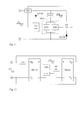
- FIG. 4 is a circuit block diagram showing utilizing the bipolar solid switch unit for structuring the synchronous regulation for turn-on and turn-off phase angles of the AC voltage, according to the present invention.
- FIG. 4 it mainly consists of:
- the mentioned circuit is for regulating the resistance, the inductive load containing the resistance or the capacitive load containing the resistance driven by the AC power, or the load in which the inductive load and the capacitive load containing the resistance connected in series.
- FIG. 5 is a circuit block diagram showing configuring the regulation for the turn-on phase angle and the turn-off phase angle to the bipolar solid switch unit, according to the present invention.
- FIG. 5 it mainly consists of:
- the mentioned circuit is for regulating the resistance, the inductive load containing the resistance or the capacitive load containing the resistance driven by the AC power, or the load in which the inductive load and the capacitive load containing the resistance connected in series.
- FIG. 6 is a circuit block diagram showing utilizing two bipolar solid switch units for structuring the synchronous regulation for turn-on and turn-off phase angles of the AC voltage, according to the present invention.
- FIG. 6 it mainly consists of:
- the mentioned circuit is for regulating the resistance, the inductive load containing the resistance or the capacitive load containing the resistance driven by the AC power, or the load in which the inductive load and the capacitive load containing the resistance connected in series.
- FIG. 7 is a circuit block diagram showing configuring the regulation for the turn-on and the turn-off phase angles to two solid switch units, according to the present invention.
- FIG. 7 it mainly consists of:
- the mentioned circuit is for regulating the resistance, the inductive load containing the resistance or the capacitive load containing the resistance driven by the AC power, or the load in which the inductive load and the capacitive load containing the resistance connected in series.
- FIG. 8 is a circuit block diagram showing utilizing the bridge rectifiers combining with the solid switch unit for structuring the synchronous regulation circuit for turn-on and turn-off phase angle of the AC voltage.
- FIG. 8 it mainly consists of:
- the mentioned circuit is for regulating the resistance, the inductive load containing the resistance or the capacitive load containing the resistance driven by the AC power, or the load in which the inductive load and the capacitive load containing the resistance connected in series.
- FIG. 9 is a circuit block diagram showing configuring the regulation for the turn-on and turn-off phase angles to the solid switch unit combined with the bridge rectifiers, according to the present invention.
- FIG. 9 it mainly consists of:
- the mentioned circuit is for regulating the resistance, the inductive load containing the resistance or the capacitive load containing the resistance driven by the AC power, or the load in which the inductive load and the capacitive load containing the resistance connected in series.
- FIG. 10 is a circuit block diagram showing utilizing the bipolar solid switch unit to structure the synchronous regulation for turn-on and turn-off phase angle of the AC voltage, and through the AC current limiting circuit device (Z10) detecting the current value, to output to the regulation circuit of turn-on and turn-off phase angle, thereby to regulate the voltage or current passing the load via the solid switch unit.
- FIG. 10 it mainly consists of:
- the mentioned circuit is for regulating the resistance, the inductive load containing the resistance or the capacitive load containing the resistance driven by the AC power, or the load in which the inductive load and the capacitive load containing the resistance connected in series.
- FIG. 11 is a circuit block diagram showing utilizing two solid switch units to structure the synchronous regulation for turn-on and turn-off phase angle of the AC voltage, and through the AC current limiting circuit device (Z10) detecting the current value, to output to the regulation circuit of turn-on and turn-off phase angle, thereby to regulate the voltage or current passing the load via the solid switch unit.
- FIG. 11 it mainly consists of:
- the mentioned circuit is for regulating the resistance, the inductive load containing the resistance or the capacitive load containing the resistance driven by the AC power, or the load in which the inductive load and the capacitive load containing the resistance connected in series.
- FIG. 12 is a circuit block diagram showing utilizing the bridge rectifiers combining with the solid switch unit to structure the synchronous regulation for turn-on and turn-off phase angle of the AC voltage, and through the AC current limiting circuit device (Z10) detecting the current value, to output to the regulation circuit of turn-on and turn-off phase angle, and to regulate the voltage or current passing through the load via the solid switch unit.
- FIG. 12 it mainly consists of:
- the mentioned circuit is for regulating the resistance, the inductive load containing the resistance or the capacitive load containing the resistance driven by the AC power, or the load in which the inductive load and the capacitive load containing the resistance connected in series.
- the output driving voltage signal of the regulation circuit of bipolar turn-on and turn-off phase angle (PD100), the configuration circuit of bipolar turn-on and turn-off phase angle (PD200), the regulation circuit of unipolar turn-on and turn-off phase angle (PD101) and (PD102), the configuration circuit of unipolar turn-on and turn-off phase angle (PD103) and (PD104) can be constituted by the followings, which includes:
Landscapes
- Engineering & Computer Science (AREA)
- Power Engineering (AREA)
- Physics & Mathematics (AREA)
- General Physics & Mathematics (AREA)
- Electromagnetism (AREA)
- Microelectronics & Electronic Packaging (AREA)
- Radar, Positioning & Navigation (AREA)
- Automation & Control Theory (AREA)
- Nonlinear Science (AREA)
- Ac-Ac Conversion (AREA)
- Rectifiers (AREA)
- Power Conversion In General (AREA)
- Control Of Electrical Variables (AREA)
Abstract
Description
- The present invention relates to a synchronous regulation for the turn-on and turn-off phase angles of the sine waveform voltage output by an AC power source, which is a novel regulation mode capable of synchronously regulating the turn-on and turn-off phase angles that breaks through the conventional regulation mode of either regulating the trigger phase angle or regulating the turn-off phase angle, and especially provided with a feature of regulating both of the turn-on and turn-off phase angles with the same phase angle, so that the sine waveform voltage of the AC power source can be kept to output in symmetrical waveforms within the range in which the turn-on and turn-off phase angles being synchronously regulated; the synchronous regulation circuit for turn-on and turn-off phase angle of the AC voltage, provided by the present invention, can be applied to regulate the voltage output by a single-phase AC power source or a multiphase AC power source, for supplying power with stable voltage to a load, or for regulating the output current to the load.
- The conventional regulation method for an AC power source is amplitude modulation (as shown in
FIG. 1 ), and till now, the control means for phase angle is to either regulate the trigger phase angle (as shown inFIG. 2 ), or regulate the turn-off phase angle (as shown inFIG. 3 ), thereby the application is limited. - The present invention provides a synchronous regulation circuit for turn-on and turn-off phase angle of the AC voltage, wherein a solid switch unit is installed between an AC power source and a load, and a phase angle regulation circuit is utilized to synchronously regulate both of the turn-on phase angle and turn-off phase angle of the solid switch unit, so that the sine waveform voltage of the AC power source can be kept to output in symmetrical waveforms within the range in which the turn-on and turn-off phase angles being synchronously regulated; the synchronous regulation circuit for turn-on and turn-off phase angle of the AC voltage, provided by the present invention, can be applied to regulate the voltage output by a single-phase AC power source or a multiphase AC power source, for supplying power with stable voltage to a load or for regulating the output current to the load.
- According to another aspect of the present invention, a synchronous regulation circuit for turn-on and turn-off phase angle of the AC voltage comprises a solid switch unit installed between an AC power source and a load, and a phase angle regulation circuit utilised to synchronously regulate both of the turn-on phase angle and turn-off phase angle of the solid switch unit, so that the sign wave voltage of the AC power source can be maintained to output symmetrical waveforms within the range in which the turn-on and turn-off phase angles are synchronously regulated. According to one embodiment, the regulation circuit includes an AC current limiting circuit device connected in series with the load; a bipolar solid switch unit; a regulation circuit of bipolar turn-on and turn-off phase angle which generates a bipolar driving voltage signal to regulate the turn-on phase angle and turn-off phase angle of the bipolar solid switch unit.
-
-
FIG. 1 is a schematic view showing the waveform of the conventional amplitude modulation type voltage regulation for the sine-waveform AC voltage. -
FIG. 2 is a schematic view showing the voltage regulation waveform of the conventional regulation for the turn-on phase angle of the sine-waveform AC voltage. -
FIG. 3 is a schematic view showing the voltage regulation waveform of the conventional regulation for the turn-off phase angle of the sine-waveform AC voltage. -
FIG. 4 is a circuit block diagram showing utilizing the bipolar solid switch unit for structuring the synchronous regulation for turn-on and turn-off phase angles of the AC voltage, according to the present invention. -
FIG. 5 is a circuit block diagram showing configuring the regulation for the turn-on phase angle and the turn-off phase angle to the bipolar solid switch unit, according to the present invention. -
FIG. 6 is a circuit block diagram showing utilizing two bipolar solid switch units for structuring the synchronous regulation for turn-on and turn-off phase angles of the AC voltage, according to the present invention. -
FIG. 7 is a circuit block diagram showing configuring the regulation for the turn-on and the turn-off phase angles to two solid switch units, according to the present invention. -
FIG. 8 is a circuit block diagram showing utilizing the bridge rectifiers combining with the solid switch unit for structuring the synchronous regulation circuit for turn-on and turn-off phase angle of the AC voltage. -
FIG. 9 is a circuit block diagram showing configuring the regulation for the turn-on and turn-off phase angles to the solid switch unit combined with the bridge rectifiers, according to the present invention. -
FIG. 10 is a circuit block diagram showing utilizing the bipolar solid switch unit to structure the synchronous regulation for turn-on and turn-off phase angle of the AC voltage, and through the AC current limiting circuit device (Z10) detecting the current value, to output to the regulation circuit of turn-on and turn-off phase angle, thereby to regulate the voltage or current passing the load via the solid switch unit. -
FIG. 11 is a circuit block diagram showing utilizing two solid switch units to structure the synchronous regulation for turn-on and turn-off phase angle of the AC voltage, and through the AC current limiting circuit device (Z10) detecting the current value, to output to the regulation circuit of turn-on and turn-off phase angle, thereby to regulate the voltage or current passing the load via the solid switch unit. -
FIG. 12 is a circuit block diagram showing utilizing the bridge rectifiers combining with the solid switch unit to structure the synchronous regulation for turn-on and turn-off phase angle of the AC voltage, and through the AC current limiting circuit device (Z10) detecting the current value, to output to the regulation circuit of turn-on and turn-off phase angle, and to regulate the voltage or current passing through the load via the solid switch unit. -
- (1000) : Bipolar solid switch unit
- (1001) , (1002) : Unipolar solid switch unit
- (BR101) , (BR102) : Bridge rectifier
- (CR101) , (CR102) : Diode
- (L101) : Load
- (PD100) : Regulation circuit of bipolar turn-on and turn-off phase angle
- (PD200) : Configuration circuit of bipolar turn-on and turn-off phase angle
- (PD101) , (PD102) : Regulation circuit of unipolar turn-on and turn-off phase angle
- (PD103) , (PD104) : Configuration circuit of unipolar turn-on and turn-off phase angle
- (Z10) : AC current limiting circuit device
- (ZD101) , (ZD102) , (ZD103) , (ZD104) : Zener diode
- The conventional regulation method for an AC power source is amplitude modulation (as shown in
FIG. 1 ), and till now, the control means for phase angle is to either regulate the trigger phase angle (as shown inFIG. 2 ), or regulate the turn-off phase angle (as shown inFIG. 3 ), thereby the application is limited. - The present invention relates to a synchronous regulation for the turn-on and turn-off phase angles of the sine waveform voltage output by an AC power source, which is a novel regulation mode capable of synchronously regulating the turn-on and turn-off phase angles that breaks through the conventional regulation mode of either regulating the trigger phase angle or regulating the turn-off phase angle, and especially provided with a feature of regulating both of the turn-on and turn-off phase angles with the same phase angle, so that the sine-waveform voltage of the AC power source can be kept to output in symmetrical waveforms within the range in which the turn-on and turn-off phase angles being synchronously regulated; the synchronous regulation circuit for turn-on and turn-off phase angle of the AC voltage, provided by the present invention, can be applied to regulate the voltage output by a single-phase AC power source or a multiphase AC power source, for supplying power with stable voltage to a load, or for regulating the output current to the load.
- The present invention provides a synchronous regulation circuit for turn-on and turn-off phase angle of the AC voltage, wherein a solid switch unit is installed between an AC power source and a load, and a phase angle regulation circuit is utilized to synchronously regulate both of the turn-on phase angle and turn-off phase angle of the solid switch unit, so that the sine-waveform voltage of the AC power source can be kept to output in symmetrical waveforms within the range in which the turn-on and turn-off phase angles being synchronously regulated; the synchronous regulation circuit for turn-on and turn-off phase angle of the AC voltage, provided by the present invention, can be applied to regulate the voltage output by a single-phase AC power source or a multiphase AC power source, for supplying power with stable voltage to a load or for regulating the output current to the load.
-
FIG. 4 is a circuit block diagram showing utilizing the bipolar solid switch unit for structuring the synchronous regulation for turn-on and turn-off phase angles of the AC voltage, according to the present invention. - As shown in
FIG. 4 , it mainly consists of: - --AC current limiting circuit device (Z10): which is constituted by one or more than one of resistive impedance, inductive impedance and capacitive impedance being connected in series, in parallel or in series and parallel and provided for being connected in series with the load (L101) and the bipolar solid switch unit (1000) then connected in parallel with the AC power source;
- --Bipolar solid switch unit (1000): which is constituted by one or more than one of following solid switch units:
- 1) The bipolar solid switch unit (1000) is composed of a bidirectional thyristor component capable of controlling the turn-on phase angle, e.g. bidirectional silicon controlled rectifier TRIAC (Triode AC semiconductor switch); through the regulation function of the regulation circuit of bipolar turn-on and turn-off phase angle (PD100) itself, a bipolar driving voltage signal is output to regulate the turn-on phase angle and the turn-off phase angle of the bipolar solid switch unit (1000) composed of the TRIAC;
- 2) The bipolar solid switch unit (1000) is composed of at least two field effect power components, e.g. a bipolar module composed of the metal oxide semiconductor field effect transistor (MOSFET) or the insulated gate bipolar transistor (IGBT); and through the regulation function of the regulation circuit of bipolar turn-on and turn-off phase angle (PD100) itself, a bipolar driving voltage signal is output to regulate the turn-on phase angle and the turn-off phase angle of the bipolar solid switch unit (1000) composed of at least two field effect power components;
- -- Regulation circuit of bipolar turn-on and turn-off phase angle (PD100): which is constituted by electronic circuit components for inputting the AC power voltage; and through the regulation function of the circuit itself, and with respect to the current value passing the AC current limiting circuit device (Z10) and the terminal voltage value of the load (L101), a bipolar driving voltage signal is output to regulate the turn-on phase angle and the turn-off phase angle of the bipolar solid switch unit (1000);
- The mentioned circuit is for regulating the resistance, the inductive load containing the resistance or the capacitive load containing the resistance driven by the AC power, or the load in which the inductive load and the capacitive load containing the resistance connected in series.
-
FIG. 5 is a circuit block diagram showing configuring the regulation for the turn-on phase angle and the turn-off phase angle to the bipolar solid switch unit, according to the present invention. - As shown in
FIG. 5 , it mainly consists of: - --AC current limiting circuit device (Z10): which is constituted by one or more than one of resistive impedance, inductive impedance and capacitive impedance being connected in series, in parallel or in series and parallel and provided for being connected in series with the load (L101) and the bipolar solid switch unit (1000) then connected in parallel with the AC power source;
- --Bipolar solid switch unit (1000): which is constituted by one or more than one of following solid switch units:
- 1) The bipolar solid switch unit (1000) is composed of a bidirectional thyristor component capable of controlling the turn-on phase angle, e.g. bidirectional silicon controlled rectifier TRIAC (Triode AC semiconductor switch); through the configuration function of the configuration circuit of bipolar turn-on and turn-off phase angle (PD200) itself, a bipolar driving voltage signal is output to regulate the turn-on phase angle and the turn-off phase angle of the bipolar solid switch unit (1000) composed of the TRIAC, through the zener diodes (ZD101), (ZD102) which are reverse-polarity connected in series;
- 2) The bipolar solid switch unit (1000) is composed of at least two field effect power components, e.g. a bipolar module compose of the metal oxide semiconductor field effect transistor (MOSFET) or the integrated gate bipolar transistor (IGBT); and through the configuration function of the configuration circuit of bipolar turn-on and turn-off phase angle (PD200) itself, a bipolar driving voltage signal is output to regulate the turn-on phase angle and the turn-off phase angle of the bipolar solid switch unit (1000) composed of at least two field effect power components, through the zener diodes (ZD101), (ZD102) which are reverse-polarity connected in series;
- -- Configuration circuit of bipolar turn-on and turn-off phase angle (PD200): which is constituted by electronic circuit components for inputting the AC power voltage; and through the configuration function of the circuit itself, a bipolar driving voltage signal is output to regulate the turn-on phase angle and the turn-off phase angle of the bipolar solid switch unit (1000) through the zener diodes (ZD101), (ZD102) which are reverse-polarity connected in series;
- --Zener diode (ZD101), (ZD102): which is constituted by at least two zener diodes, reverse-polarity connected in series for generating the bipolar voltage differentiation, and is provided for being connected in series between a bipolar driving voltage signal output terminal of the regulation circuit of bipolar turn-on and turn-off phase angle (PD100) and a bipolar driving voltage signal input terminal of the bipolar solid switch unit (1000); the zener diode (ZD101), (ZD102) can be replaced by a bidirectional zener diode having the same performance;
- The mentioned circuit is for regulating the resistance, the inductive load containing the resistance or the capacitive load containing the resistance driven by the AC power, or the load in which the inductive load and the capacitive load containing the resistance connected in series.
-
FIG. 6 is a circuit block diagram showing utilizing two bipolar solid switch units for structuring the synchronous regulation for turn-on and turn-off phase angles of the AC voltage, according to the present invention. - As shown in
FIG. 6 , it mainly consists of: - --AC current limiting circuit device (Z10): which is constituted by one or more than one of resistive impedance, inductive impedance and capacitive impedance being connected in series, in parallel or in series and parallel and provided for being connected in series with the load (L101) and the bipolar solid switch unit (1000) then connected in parallel with the AC power source;
- --Bipolar solid switch unit (1000): which is constituted by a unipolar solid switch unit (1001) and a unipolar solid switch unit (1002) being reverse-polarity connected in parallel; the unipolar solid switch unit (1001) and the unipolar solid switch unit (1002) are composed of one or more than one of following solid switch units:
- 1) Constituted by at least two unipolar solid switch units (1001, 1002) capable of controlling the turn-on phase angle, e.g. at least two silicon controlled rectifiers (SCRs) being reverse-polarity connected in parallel for forming the bipolar solid switch unit (1000); and through the regulation functions of the regulation circuit of unipolar turn-on and turn-off phase angle (PD101) itself and the regulation circuit of unipolar turn-on and turn-off phase angle (PD102) itself, the driving voltage signals having different polarities are respectively output to control the turn-on phase angle and the turn-off phase angle of the unipolar solid switch unit (1001) and the unipolar solid switch unit (1002);
- 2) the unipolar solid switch unit (1001) and the unipolar solid switch unit (1002) are composed of at least two field effect power components being reverse-polarity connected in parallel to form the bipolar solid switch unit (1000), e.g. the bipolar module composed of the MOSFET and IGBT serving as the bipolar solid switch unit (1000); and through the regulation functions of the regulation circuit of unipolar turn-on and turn-off phase angle (PD101) itself and the regulation function of the regulation circuit of unipolar turn-on and turn-off phase angle (PD102) itself, the driving voltage signals having different polarities are respectively output to control the turn-on phase angle and the turn-off phase angle of the two field effect power components which are connected in parallel and in different polarities for respectively forming the unipolar solid switch unit (1001) and the unipolar solid switch unit (1002);
- -- Regulation circuit of unipolar turn-on and turn-off phase angle (PD101): which is constituted by electronic circuit components and normal-polarity connected in series with the diode (CR101) for inputting an AC voltage of a first polarity; and through the regulation function of the circuit itself and with respect to the current value passing the AC current limiting circuit device (Z10) and the terminal voltage of the load (L101), a driving voltage signal having the same polarity as the unipolar solid switch unit (1001) is output to control the turn-on phase angle and the turn-off phase angle of the unipolar solid switch unit (1001);
- -- Configuration circuit of unipolar turn-on and turn-off phase angle (PD102): which is constituted by electronic circuit components and normal-polarity connected in series with the diode (CR102) for inputting an AC voltage of a second polarity; and through the regulation function of the circuit itself and with respect to the current value passing the AC current limiting circuit device (Z10) and the terminal voltage of the load (L101), a driving voltage signal having the same polarity as the unipolar solid switch unit (1002) is output to control the turn-on phase angle and the turn-off phase angle of the unipolar solid switch unit (1002);
- --Diode (CR101): which is constituted by the rectifying diode, and the diode (CR101) and the unipolar solid switch unit (1001) are normal-polarity connected in series with the regulation circuit of unipolar turn-on and turn-off phase angle (PD101);
- --Diode (CR102): which is constituted by the rectifying diode, and the diode (CR102) and the unipolar solid switch unit (1002) are normal-polarity connected in series with the configuration circuit of unipolar turn-on and turn-off phase angle (PD102);
- The mentioned circuit is for regulating the resistance, the inductive load containing the resistance or the capacitive load containing the resistance driven by the AC power, or the load in which the inductive load and the capacitive load containing the resistance connected in series.
-
FIG. 7 is a circuit block diagram showing configuring the regulation for the turn-on and the turn-off phase angles to two solid switch units, according to the present invention. - As shown in
FIG. 7 , it mainly consists of: - --AC current limiting circuit device (Z10): which is constituted by one or more than one of resistive impedance, inductive impedance and capacitive impedance being connected in series, in parallel or in series and parallel and provided for being connected in series with the load (L101) and the bipolar solid switch unit (1000) then connected in parallel with the AC power source;
- --Bipolar solid switch unit (1000): which is constituted by a unipolar solid switch unit (1001) and a unipolar solid switch unit (1002) being reverse-polarity connected in parallel; the unipolar solid switch unit (1001) and the unipolar solid switch unit (1002) are composed of one or more than one of following solid switch units:
- 1) Constituted by at least two unipolar solid switch units (1001, 1002) capable of controlling the turn-on phase angle, e.g. at least two silicon controlled rectifiers (SCRs) being reverse-polarity connected in parallel for forming the bipolar solid switch unit (1000); and through the configuration functions of the configuration circuit of single-polarity turn-on and turn-off phase angle (PD103) itself and the configuration circuit of single-polarity turn-on and turn-off phase angle (PD104) itself, the driving voltage signals having different polarities are respectively output, through the zener diode (ZD103) and the zener diode (ZD104), to the unipolar solid switch unit (1001) and unipolar solid switch unit (1002) for respectively controlling the turn-on phase angle and the turn-off phase angle of the unipolar solid switch unit (1001) and unipolar solid switch unit (1002);
- 2) the unipolar solid switch unit (1001) and the unipolar solid switch unit (1002) are composed of at least two field effect power components being reverse-polarity connected in parallel to form the bipolar solid switch unit (1000), e.g. the bipolar module composed of the MOSFET and IGBT serving as the bipolar solid switch unit (1000); and through the configuration functions of the configuration circuit of single-polarity turn-on and turn-off phase angle (PD103) itself and the configuration circuit of single-polarity turn-on and turn-off phase angle (PD104) itself, the driving voltage signals having different polarities are respectively output, through the zener diode (ZD103) and the zener diode (ZD104), to the unipolar solid switch unit (1001) and the unipolar solid switch unit (1002) for respectively controlling the turn-on phase angle and the turn-off phase angle of the two field effect power components which are connected in parallel and in different polarities;
- -- Configuration circuit of unipolar turn-on and turn-off phase angle (PD103): which is constituted by electronic circuit components and normal-polarity connected in series with the diode (CR101) for inputting an AC voltage of a first polarity; and through the configuration function of the circuit itself, a driving voltage signal having the same polarity as the unipolar solid switch unit (1001) is output to control the turn-on phase angle and the turn-off phase angle of the unipolar solid switch unit (1001);
- -- Configuration circuit of unipolar turn-on and turn-off phase angle (PD104): which is constituted by electronic circuit components and normal-polarity connected in series with the diode (CR102) for inputting an AC voltage of a second polarity; and through the configuration function of the circuit itself, a driving voltage signal having the same polarity as the unipolar solid switch unit (1002) is output to control the turn-on phase angle and the turn-off phase angle of the unipolar solid switch unit (1002);
- --Diode (CR101): which is constituted by the rectifying diode, and the diode (CR101) and the unipolar solid switch unit (1001) are normal-polarity connected in series with the regulation circuit of unipolar turn-on and turn-off phase angle (PD101);
- --Diode (CR102): which is constituted by the rectifying diode, and the diode (CR102) and the unipolar solid switch unit (1002) are normal-polarity connected in series with the configuration circuit of unipolar turn-on and turn-off phase angle (PD102);
- --Zener diode (ZD103): which is constituted by the zener diode having zener voltage effect or the forward bias diode for being connected in series between a driving voltage signal output terminal of the configuration circuit of unipolar turn-on and turn-off phase angle (PD103) and a driving voltage signal input terminal of the unipolar solid switch unit (1001);
- --Zener diode (ZD104): which is constituted by the zener diode having zener voltage effect or the forward bias diode for being connected in series between a driving voltage signal output terminal of the configuration circuit of unipolar turn-on and turn-off phase angle (PD104) and a driving voltage signal input terminal of the unipolar solid switch unit (1002);
- The mentioned circuit is for regulating the resistance, the inductive load containing the resistance or the capacitive load containing the resistance driven by the AC power, or the load in which the inductive load and the capacitive load containing the resistance connected in series.
-
FIG. 8 is a circuit block diagram showing utilizing the bridge rectifiers combining with the solid switch unit for structuring the synchronous regulation circuit for turn-on and turn-off phase angle of the AC voltage. - As shown in
FIG. 8 , it mainly consists of: - --AC current limiting circuit device (Z10): which is constituted by one or more than one of resistive impedance, inductive impedance and capacitive impedance being connected in series, in parallel or in series and parallel and provided for being connected in series between the AC power source and an AC input terminal of the bridge rectifier (BR101);
- --Unipolar solid switch unit (1001): which is constituted by one or more than one of following solid switch units:
- 1) Constituted by the unipolar solid switch unit (1001) capable of controlling the turn-on phase angle, e.g. silicon controlled rectifier (SCR); and through the regulation function of the regulation circuit of unipolar turn-on and turn-off phase angle (PD101) itself, a driving voltage signal is output to control the turn-on phase angle and the turn-off phase angle of the unipolar solid switch unit (1001) composed of silicon controlled rectifier (SCR);
- 2) the field effect power component serving as the unipolar solid switch unit (1001), e.g. MOSFET and IGBT; and through the regulation function of the regulation circuit of unipolar turn-on and turn-off phase angle (PD101), a driving voltage signal is output to regulate the turn-on phase angle and the turn-off phase angle of the unipolar solid switch unit (1001) composed of the field effect power component;
- -- Regulation circuit of unipolar turn-on and turn-off phase angle (PD101): which is constituted by electronic circuit components and provided for being connected in parallel to a DC output terminal of the bridge rectifier (BR102); and through the regulation function of the circuit itself and with respect to the current value passing the AC current limiting circuit device (Z10) and the terminal voltage of the load (L101), a driving voltage signal having the same polarity as the unipolar solid switch unit (1001) is output to control the turn-on phase angle and the turn-off phase angle of the unipolar solid switch unit (1001);
- --Bridge rectifier (BR101): which is constituted by at least four rectifying diodes, in which the AC power input terminal is provided for being connected in series to the AC current limiting circuit device (Z10) so as to be connected to the AC power source, and is provided with the output terminals having anode and cathode of the DC power source; for rectifying the AC power source to DC power source, so as to output to the unipolar solid switch unit (1001) and the load (L101) connected in series;
- --Bridge rectifier (BR102): which is constituted by at least four rectifying diodes and provided with two input terminals for receiving the AC power source and the output terminals having anode and cathode for outputting the DC power source; for rectifying the AC power source to DC power source, so as to output to the regulation circuit of unipolar turn-on and turn-off phase angle (PD101) then further output the driving voltage signal to the unipolar solid switch unit (1001);
- The mentioned circuit is for regulating the resistance, the inductive load containing the resistance or the capacitive load containing the resistance driven by the AC power, or the load in which the inductive load and the capacitive load containing the resistance connected in series.
-
FIG. 9 is a circuit block diagram showing configuring the regulation for the turn-on and turn-off phase angles to the solid switch unit combined with the bridge rectifiers, according to the present invention. - As shown in
FIG. 9 , it mainly consists of: - --AC current limiting circuit device (Z10): which is constituted by one or more than one of resistive impedance, inductive impedance and capacitive impedance being connected in series, in parallel or in series and parallel, and one terminal thereof is connected to one terminal of the AC power source, and the other terminal thereof is connected in series with the load (L101) for leading to the AC input terminal of the bridge rectifier (BR101), and the other AC input terminal of the bridge rectifier (BR101) is connected to the other terminal of the AC power source;
- --Unipolar solid switch unit (1001): which is constituted by one or more than one of following solid switch units:
- 1) Constituted by the unipolar solid switch unit (1001) capable of controlling the turn-on phase angle, e.g. silicon controlled rectifier (SCR); and through the regulation function of the regulation circuit of unipolar turn-on and turn-off phase angle (PD101) itself and with respect to the current value passing the AC current limiting circuit device (Z10) and the terminal voltage value of the load (L101), a driving voltage signal is output, through the zener diode (ZD103), to control the turn-on phase angle and the turn-off phase angle of the unipolar solid switch unit (1001) composed of silicon controlled rectifier (SCR);
- 2) the field effect power component serving as the unipolar solid switch unit (1001), e.g. MOSFET and IGBT; and through the regulation function of the regulation circuit of unipolar turn-on and turn-off phase angle (PD101) and with respect to the current value passing the AC current limiting circuit device (Z10) and the terminal voltage value of the load (L101), a driving voltage signal is output, through the zener diode (ZD103), to regulate the turn-on phase angle and the turn-off phase angle of the unipolar solid switch unit (1001) composed of the field effect power component;
- -- Configuration circuit of unipolar turn-on and turn-off phase angle (PD103): constituted by electronic circuit components and provided for being connected in parallel to the DC output terminal of the bridge rectifier (BR101); through the configuration function of the circuit itself, a driving voltage signal is output, and through the zener diode (ZD103), to control the turn-on phase angle and the turn-off phase angle of the unipolar solid switch unit (1001);
- --Bridge rectifier (BR101): which is constituted by at least four rectifying diodes and provided with two input terminals for receiving the AC power source and the output terminals having anode and cathode for outputting the DC power source; for rectifying the AC power source to DC power source, so as to output to the unipolar switch unit (1001) and the configuration circuit of single-polarity turn-on and turn-off phase angle (PD103);
- --Zener diode (ZD103): which is constituted by the zener diode having zener voltage effect or the forward bias diode for being connected in series between a driving voltage signal output terminal of the configuration circuit of unipolar turn-on and turn-off phase angle (PD103) and a driving voltage signal input terminal of the unipolar solid switch unit (1001);
- The mentioned circuit is for regulating the resistance, the inductive load containing the resistance or the capacitive load containing the resistance driven by the AC power, or the load in which the inductive load and the capacitive load containing the resistance connected in series.
-
FIG. 10 is a circuit block diagram showing utilizing the bipolar solid switch unit to structure the synchronous regulation for turn-on and turn-off phase angle of the AC voltage, and through the AC current limiting circuit device (Z10) detecting the current value, to output to the regulation circuit of turn-on and turn-off phase angle, thereby to regulate the voltage or current passing the load via the solid switch unit. - As shown in
FIG. 10 , it mainly consists of: - --AC current limiting circuit device (Z10): which is constituted by one or more than one of resistive impedance, inductive impedance and capacitive impedance being connected in series, in parallel or in series and parallel and provided for being connected in series with the load (L101) and the bipolar solid switch unit (1000) then connected in parallel with the AC power source;
- --Bipolar solid switch unit (1000): which is constituted by one or more than one of following solid switch units:
- 1) The bipolar solid switch unit (1000) is composed of a bidirectional thyristor component capable of controlling the turn-on phase angle, e.g. bidirectional silicon controlled rectifier TRIAC (Triode AC semiconductor switch); through the regulation function of the regulation circuit of bipolar turn-on and turn-off phase angle (PD100) itself and with respect to the current value passing the AC current limiting circuit device (Z10) and the terminal voltage of the load (L101), a bipolar driving voltage signal is output to regulate the turn-on phase angle and the turn-off phase angle of the bipolar solid switch unit (1000) composed of the TRIAC;
- 2) The bipolar solid switch unit (1000) is composed of at least two field effect power components, e.g. a bipolar module composed of the metal oxide semiconductor field effect transistor (MOSFET) or the insulated gate bipolar transistor (IGBT)bipolar solid switch unit; and through the regulation function of the regulation circuit of bipolar turn-on and turn-off phase angle (PD100) itself and with respect to the current value passing the AC current limiting circuit device (Z10) and the terminal voltage of the load (L101), a bipolar driving voltage signal is output to regulate the turn-on phase angle and the turn-off phase angle of the bipolar solid switch unit (1000) composed of at least two field effect power components;
- -- Regulation circuit of bipolar turn-on and turn-off phase angle (PD100): which is constituted by electronic circuit components for inputting the AC power voltage; and through the regulation function of the circuit itself, and with respect to the current value passing the AC current limiting circuit device (Z10) and the terminal voltage value of the load (L101), a bipolar driving voltage signal is output to regulate the turn-on phase angle and the turn-off phase angle of the bipolar solid switch unit (1000);
- The mentioned circuit is for regulating the resistance, the inductive load containing the resistance or the capacitive load containing the resistance driven by the AC power, or the load in which the inductive load and the capacitive load containing the resistance connected in series.
-
FIG. 11 is a circuit block diagram showing utilizing two solid switch units to structure the synchronous regulation for turn-on and turn-off phase angle of the AC voltage, and through the AC current limiting circuit device (Z10) detecting the current value, to output to the regulation circuit of turn-on and turn-off phase angle, thereby to regulate the voltage or current passing the load via the solid switch unit. - As shown in
FIG. 11 , it mainly consists of: - --AC current limiting circuit device (Z10): which is constituted by one or more than one of resistive impedance, inductive impedance and capacitive impedance being connected in series, in parallel or in series and parallel and provided for being connected in series with the load (L101) and the bipolar solid switch unit (1000) then connected in parallel with the AC power source;
- --Bipolar solid switch unit (1000): which is constituted by a unipolar solid switch unit (1001) and a unipolar solid switch unit (1002) being reverse-polarity connected in parallel; the unipolar solid switch unit (1001) and the unipolar solid switch unit (1002) are composed of one or more than one of following solid switch units:
- 1) Constituted by at least two unipolar solid switch units (1001, 1002) capable of controlling the turn-on phase angle, e.g. at least two silicon controlled rectifiers (SCRs) being reverse-polarity connected in parallel for forming the bipolar solid switch unit (1000); and through the regulation functions of the regulation circuit of unipolar turn-on and turn-off phase angle (PD101) itself and the regulation circuit of unipolar turn-on and turn-off phase angle (PD102) itself and with respect to the current value passing the AC current limiting circuit device (Z10) and the terminal voltage value of the load (L101), the driving voltage signals having different polarities are respectively output to control the turn-on phase angle and the turn-off phase angle of the unipolar solid switch unit (1001) and the unipolar solid switch unit (1002);
- 2) the unipolar solid switch unit (1001) and the unipolar solid switch unit (1002) are composed of at least two field effect power components being reverse-polarity connected in parallel to form the bipolar solid switch unit (1000), e.g. the bipolar module composed of the MOSFET and IGBT serving as the bipolar solid switch unit (1000); and through the regulation functions of the regulation circuit of unipolar turn-on and turn-off phase angle (PD101) itself and the regulation circuit of unipolar turn-on and turn-off phase angle (PD102) itself and with respect to the current value passing the AC current limiting circuit device (Z10) and the terminal voltage value of the load (L101), the driving voltage signals having different polarities are respectively output to control the turn-on phase angle and the turn-off phase angle of the two field effect power components which are connected in parallel and in different polarities for respectively forming the unipolar solid switch unit (1001) and the unipolar solid switch unit (1002);
- -- Regulation circuit of unipolar turn-on and turn-off phase angle (PD101): which is constituted by electronic circuit components and normal-polarity connected in series with the diode (CR101) for inputting an AC voltage of a first polarity; and through the regulation function of the circuit itself and with respect to the current value passing the AC current limiting circuit device (Z10) and the terminal voltage of the load (L101), a driving voltage signal having the same polarity as the unipolar solid switch unit (1001) is output to control the turn-on phase angle and the turn-off phase angle of the unipolar solid switch unit (1001);
- -- Configuration circuit of unipolar turn-on and turn-off phase angle (PD102): which is constituted by electronic circuit components and normal-polarity connected in series with the diode (CR102) for inputting an AC voltage of a second polarity; and through the regulation function of the circuit itself and with respect to the current value passing the AC current limiting circuit device (Z10) and the terminal voltage of the load (L101), a driving voltage signal having the same polarity as the unipolar solid switch unit (1002) is output to control the turn-on phase angle and the turn-off phase angle of the unipolar solid switch unit (1002);
- --Diode (CR101): which is constituted by the rectifying diode, and the diode (CR101) and the unipolar solid switch unit (1001) are normal-polarity connected in series with the regulation circuit of unipolar turn-on and turn-off phase angle (PD101);
- --Diode (CR102): which is constituted by the rectifying diode, and the diode (CR102) and the unipolar solid switch unit (1002) are normal-polarity connected in series with the configuration circuit of unipolar turn-on and turn-off phase angle (PD102);
- The mentioned circuit is for regulating the resistance, the inductive load containing the resistance or the capacitive load containing the resistance driven by the AC power, or the load in which the inductive load and the capacitive load containing the resistance connected in series.
-
FIG. 12 is a circuit block diagram showing utilizing the bridge rectifiers combining with the solid switch unit to structure the synchronous regulation for turn-on and turn-off phase angle of the AC voltage, and through the AC current limiting circuit device (Z10) detecting the current value, to output to the regulation circuit of turn-on and turn-off phase angle, and to regulate the voltage or current passing through the load via the solid switch unit. - As shown in
FIG. 12 , it mainly consists of: - --AC current limiting circuit device (Z10): which is constituted by one or more than one of resistive impedance, inductive impedance and capacitive impedance being connected in series, in parallel or in series and parallel and provided for being connected in series between the AC power source and an AC input terminal of the bridge rectifier (BR101);
- --Unipolar solid switch unit (1001): which is constituted by one or more than one of following solid switch units:
- 1) Constituted by the unipolar solid switch unit (1001) capable of controlling the turn-on phase angle, e.g. silicon controlled rectifier (SCR); and through the regulation function of the regulation circuit of unipolar turn-on and turn-off phase angle (PD101) itself and with respect to the current value passing the AC current limiting circuit device (Z10) and the terminal voltage value of the load (L101), a driving voltage signal is output to control the turn-on phase angle and the turn-off phase angle of the unipolar solid switch unit (1001) composed of silicon controlled rectifier (SCR);
- 2) the field effect power component serving as the unipolar solid switch unit (1001), e.g. MOSFET and IGBT; and through the regulation function of the regulation circuit of unipolar turn-on and turn-off phase angle (PD101) itself and with respect to the current value passing the AC current limiting circuit device (Z10) and the terminal voltage value of the load (L101), a driving voltage signal is output to regulate the turn-on phase angle and the turn-off phase angle of the unipolar solid switch unit (1001) composed of the field effect power component;
- -- Regulation circuit of unipolar turn-on and turn-off phase angle (PD101): which is constituted by electronic circuit components, and connected in parallel to a DC output terminal of the bridge rectifier (BR102); and through the regulation function of the circuit itself and with respect to the current value passing the AC current limiting circuit device (Z10) and the terminal voltage of the load (L101), a driving voltage signal having the same polarity as the unipolar solid switch unit (1001) is output to control the turn-on phase angle and the turn-off phase angle of the unipolar solid switch unit (1001);
- --Bridge rectifier (BR101): which is constituted by at least four rectifying diodes, in which the AC power input terminal is provided for being connected in series to the AC current limiting circuit device (Z10) so as to be connected to the AC power source, and is provided with the output terminals having anode and cathode of the DC power source; for rectifying the AC power source to DC power source, so as to output to the unipolar solid switch unit (1001) and the load (L101) connected in series;
- --Bridge rectifier (BR102): which is constituted by at least four rectifying diodes and provided with two input terminals for receiving the AC power source and the output terminals having anode and cathode for outputting the DC power source; for rectifying the AC power source to DC power source, so as to output to the regulation circuit of unipolar turn-on and turn-off phase angle (PD101) then further output the driving voltage signal to the unipolar solid switch unit (1001);
- The mentioned circuit is for regulating the resistance, the inductive load containing the resistance or the capacitive load containing the resistance driven by the AC power, or the load in which the inductive load and the capacitive load containing the resistance connected in series.
- According to the synchronous regulation circuit for turn-on and turn-off phase angle of the AC voltage provided by the present invention, the output driving voltage signal of the regulation circuit of bipolar turn-on and turn-off phase angle (PD100), the configuration circuit of bipolar turn-on and turn-off phase angle (PD200), the regulation circuit of unipolar turn-on and turn-off phase angle (PD101) and (PD102), the configuration circuit of unipolar turn-on and turn-off phase angle (PD103) and (PD104) can be constituted by the followings, which includes:
- 1) Directly outputting the power signal to drive the mated solid switch unit;
- 2) Utilizing a photoelectric coupling device for insulation and outputting the power signal to drive the mated solid switch unit; and
- 3) Utilizing a pulse transformer for insulation and outputting the power signal to drive the mated solid switch unit.
Claims (10)
- A synchronous regulation circuit for turn-on and turn-off phase angle of the AC voltage, wherein a solid switch unit is installed between an AC power source and a load, and a phase angle regulation circuit is utilized to synchronously regulate both of the turn-on phase angle and turn-off phase angle of the solid switch unit, so that the sine waveform voltage of the AC power source can be kept to output in symmetrical waveforms within the range in which the turn-on and turn-off phase angles being synchronously regulated; the synchronous regulation circuit for turn-on and turn-off phase angle of the AC voltage, provided by the present invention, can be applied to regulate the voltage output by a single-phase AC power source or a multiphase AC power source, for supplying power with stable voltage to a load or for regulating the output current to the load, which mainly consists of:--AC current limiting circuit device (Z10): which is constituted by one or more than one of resistive impedance, inductive impedance and capacitive impedance being connected in series, in parallel or in series and parallel and provided for being connected in series with the load (L101) and the bipolar solid switch unit (1000) then connected in parallel with the AC power source;--Bipolar solid switch unit (1000): which is constituted by one or more than one of following solid switch units:1) The bipolar solid switch unit (1000) is composed of a bidirectional thyristor component capable of controlling the turn-on phase angle, e.g. bidirectional silicon controlled rectifier TRIAC (Triode AC semiconductor switch); through the regulation function of the regulation circuit of bipolar turn-on and turn-off phase angle (PD100) itself, a bipolar driving voltage signal is output to regulate the turn-on phase angle and the turn-off phase angle of the bipolar solid switch unit (1000) composed of the TRIAC;2) The bipolar solid switch unit (1000) is composed of at least two field effect power components, e.g. a bipolar module composed of the metal oxide semiconductor field effect transistor (MOSFET) or the insulated gate bipolar transistor (IGBT); and through the regulation function of the regulation circuit of bipolar turn-on and turn-off phase angle (PD100) itself, a bipolar driving voltage signal is output to regulate the turn-on phase angle and the turn-off phase angle of the bipolar solid switch unit (1000) composed of at least two field effect power components;-- Regulation circuit of bipolar turn-on and turn-off phase angle (PD100): which is constituted by electronic circuit components for inputting the AC power voltage; and through the regulation function of the circuit itself, and with respect to the current value passing the AC current limiting circuit device (Z10) and the terminal voltage value of the load (L101), a bipolar driving voltage signal is output to regulate the turn-on phase angle and the turn-off phase angle of the bipolar solid switch unit (1000);
The mentioned circuit is for regulating the resistance, the inductive load containing the resistance or the capacitive load containing the resistance driven by the AC power, or the load in which the inductive load and the capacitive load containing the resistance connected in series. - A synchronous regulation circuit for turn-on and turn-off phase angle of the AC voltage as claimed in claim 1, wherein it includes configuring the regulation for the turn-on phase angle and the turn-off phase angle to the bipolar solid switch unit, which mainly consists of:--AC current limiting circuit device (Z10): which is constituted by one or more than one of resistive impedance, inductive impedance and capacitive impedance being connected in series, in parallel or in series and parallel and provided for being connected in series with the load (L101) and the bipolar solid switch unit (1000) then connected in parallel with the AC power source;--Bipolar solid switch unit (1000): which is constituted by one or more than one of following solid switch units:1) The bipolar solid switch unit (1000) is composed of a bidirectional thyristor component capable of controlling the turn-on phase angle, e.g. bidirectional silicon controlled rectifier TRIAC (Triode AC semiconductor switch); through the configuration function of the configuration circuit of bipolar turn-on and turn-off phase angle (PD200) itself, a bipolar driving voltage signal is output to regulate the turn-on phase angle and the turn-off phase angle of the bipolar solid switch unit (1000) composed of the TRIAC, through the zener diodes (ZD101), (ZD102) which are reverse-polarity connected in series;2) The bipolar solid switch unit (1000) is composed of at least two field effect power components, e.g. a bipolar module compose of the metal oxide semiconductor field effect transistor (MOSFET) or the integrated gate bipolar transistor (IGBT); and through the configuration function of the configuration circuit of bipolar turn-on and turn-off phase angle (PD200) itself, a bipolar driving voltage signal is output to regulate the turn-on phase angle and the turn-off phase angle of the bipolar solid switch unit (1000) composed of at least two field effect power components, through the zener diodes (ZD101), (ZD102) which are reverse-polarity connected in series;-- Configuration circuit of bipolar turn-on and turn-off phase angle (PD200): which is constituted by electronic circuit components for inputting the AC power voltage; and through the configuration function of the circuit itself, a bipolar driving voltage signal is output to regulate the turn-on phase angle and the turn-off phase angle of the bipolar solid switch unit (1000) through the zener diodes (ZD101), (ZD102) which are reverse-polarity connected in series;--Zener diode (ZD101), (ZD102): which is constituted by at least two zener diodes, reverse-polarity connected in series for generating the bipolar voltage differentiation, and is provided for being connected in series between a bipolar driving voltage signal output terminal of the regulation circuit of bipolar turn-on and turn-off phase angle (PD100) and a bipolar driving voltage signal input terminal of the bipolar solid switch unit (1000); the zener diode (ZD101), (ZD102) can be replaced by a bidirectional zener diode having the same performance;
The mentioned circuit is for regulating the resistance, the inductive load containing the resistance or the capacitive load containing the resistance driven by the AC power, or the load in which the inductive load and the capacitive load containing the resistance connected in series. - A synchronous regulation circuit for turn-on and turn-off phase angle of the AC voltage as claimed in claim 1, wherein it includes utilizing two bipolar solid switch units for structuring the synchronous regulation for turn-on and turn-off phase angles of the AC voltage, which mainly consists of:--AC current limiting circuit device (Z10): which is constituted by one or more than one of resistive impedance, inductive impedance and capacitive impedance being connected in series, in parallel or in series and parallel and provided for being connected in series with the load (L101) and the bipolar solid switch unit (1000) then connected in parallel with the AC power source;--Bipolar solid switch unit (1000): which is constituted by a unipolar solid switch unit (1001) and a unipolar solid switch unit (1002) being reverse-polarity connected in parallel; the unipolar solid switch unit (1001) and the unipolar solid switch unit (1002) are composed of one or more than one of following solid switch units:1) Constituted by at least two unipolar solid switch units (1001, 1002) capable of controlling the turn-on phase angle, e.g. at least two silicon controlled rectifiers (SCRs) being reverse-polarity connected in parallel for forming the bipolar solid switch unit (1000); and through the regulation functions of the regulation circuit of unipolar turn-on and turn-off phase angle (PD101) itself and the regulation circuit of unipolar turn-on and turn-off phase angle (PD102) itself, the driving voltage signals having different polarities are respectively output to control the turn-on phase angle and the turn-off phase angle of the unipolar solid switch unit (1001) and the unipolar solid switch unit (1002);2) the unipolar solid switch unit (1001) and the unipolar solid switch unit (1002) are composed of at least two field effect power components being reverse-polarity connected in parallel to form the bipolar solid switch unit (1000), e.g. the bipolar module composed of the MOSFET and IGBT serving as the bipolar solid switch unit (1000); and through the regulation functions of the regulation circuit of unipolar turn-on and turn-off phase angle (PD101) itself and the regulation function of the regulation circuit of unipolar turn-on and turn-off phase angle (PD102) itself, the driving voltage signals having different polarities are respectively output to control the turn-on phase angle and the turn-off phase angle of the two field effect power components which are connected in parallel and in different polarities for respectively forming the unipolar solid switch unit (1001) and the unipolar solid switch unit (1002);-- Regulation circuit of unipolar turn-on and turn-off phase angle (PD101): which is constituted by electronic circuit components and normal-polarity connected in series with the diode (CR101) for inputting an AC voltage of a first polarity; and through the regulation function of the circuit itself and with respect to the current value passing the AC current limiting circuit device (Z10) and the terminal voltage of the load (L101), a driving voltage signal having the same polarity as the unipolar solid switch unit (1001) is output to control the turn-on phase angle and the turn-off phase angle of the unipolar solid switch unit (1001);-- Configuration circuit of unipolar turn-on and turn-off phase angle (PD102): which is constituted by electronic circuit components and normal-polarity connected in series with the diode (CR102) for inputting an AC voltage of a second polarity; and through the regulation function of the circuit itself and with respect to the current value passing the AC current limiting circuit device (Z10) and the terminal voltage of the load (L101), a driving voltage signal having the same polarity as the unipolar solid switch unit (1002) is output to control the turn-on phase angle and the turn-off phase angle of the unipolar solid switch unit (1002);--Diode (CR101): which is constituted by the rectifying diode, and the diode (CR101) and the unipolar solid switch unit (1001) are normal-polarity connected in series with the regulation circuit of unipolar turn-on and turn-off phase angle (PD101);--Diode (CR102): which is constituted by the rectifying diode, and the diode (CR102) and the unipolar solid switch unit (1002) are normal-polarity connected in series with the configuration circuit of unipolar turn-on and turn-off phase angle (PD102);
The mentioned circuit is for regulating the resistance, the inductive load containing the resistance or the capacitive load containing the resistance driven by the AC power, or the load in which the inductive load and the capacitive load containing the resistance connected in series. - A synchronous regulation circuit for turn-on and turn-off phase angle of the AC voltage as claimed in claim 1, wherein it includes configuring the regulation for the turn-on and the turn-off phase angles to two solid switch units, which mainly consists of:--AC current limiting circuit device (Z10): which is constituted by one or more than one of resistive impedance, inductive impedance and capacitive impedance being connected in series, in parallel or in series and parallel and provided for being connected in series with the load (L101) and the bipolar solid switch unit (1000) then connected in parallel with the AC power source;--Bipolar solid switch unit (1000): which is constituted by a unipolar solid switch unit (1001) and a unipolar solid switch unit (1002) being reverse-polarity connected in parallel; the unipolar solid switch unit (1001) and the unipolar solid switch unit (1002) are composed of one or more than one of following solid switch units:1) Constituted by at least two unipolar solid switch units (1001, 1002) capable of controlling the turn-on phase angle, e.g. at least two silicon controlled rectifiers (SCRs) being reverse-polarity connected in parallel for forming the bipolar solid switch unit (1000); and through the configuration functions of the configuration circuit of single-polarity turn-on and turn-off phase angle (PD103) itself and the configuration circuit of single-polarity turn-on and turn-off phase angle (PD104) itself, the driving voltage signals having different polarities are respectively output, through the zener diode (ZD103) and the zener diode (ZD104), to the unipolar solid switch unit (1001) and unipolar solid switch unit (1002) for respectively controlling the turn-on phase angle and the turn-off phase angle of the unipolar solid switch unit (1001) and unipolar solid switch unit (1002);2) the unipolar solid switch unit (1001) and the unipolar solid switch unit (1002) are composed of at least two field effect power components being reverse-polarity connected in parallel to form the bipolar solid switch unit (1000), e.g. the bipolar module composed of the MOSFET and IGBT serving as the bipolar solid switch unit (1000); and through the configuration functions of the configuration circuit of single-polarity turn-on and turn-off phase angle (PD103) itself and the configuration circuit of single-polarity turn-on and turn-off phase angle (PD104) itself, the driving voltage signals having different polarities are respectively output, through the zener diode (ZD103) and the zener diode (ZD104), to the unipolar solid switch unit (1001) and the unipolar solid switch unit (1002) for respectively controlling the turn-on phase angle and the turn-off phase angle of the two field effect power components which are connected in parallel and in different polarities;-- Configuration circuit of unipolar turn-on and turn-off phase angle (PD103): which is constituted by electronic circuit components and normal-polarity connected in series with the diode (CR101) for inputting an AC voltage of a first polarity; and through the configuration function of the circuit itself, a driving voltage signal having the same polarity as the unipolar solid switch unit (1001) is output to control the turn-on phase angle and the turn-off phase angle of the unipolar solid switch unit (1001);-- Configuration circuit of unipolar turn-on and turn-off phase angle (PD104): which is constituted by electronic circuit components and normal-polarity connected in series with the diode (CR102) for inputting an AC voltage of a second polarity; and through the configuration function of the circuit itself, a driving voltage signal having the same polarity as the unipolar solid switch unit (1002) is output to control the turn-on phase angle and the turn-off phase angle of the unipolar solid switch unit (1002);--Diode (CR101): which is constituted by the rectifying diode, and the diode (CR101) and the unipolar solid switch unit (1001) are normal-polarity connected in series with the regulation circuit of unipolar turn-on and turn-off phase angle (PD101);--Diode (CR102): which is constituted by the rectifying diode, and the diode (CR102) and the unipolar solid switch unit (1002) are normal-polarity connected in series with the configuration circuit of unipolar turn-on and turn-off phase angle (PD102);--Zener diode (ZD103): which is constituted by the zener diode having zener voltage effect or the forward bias diode for being connected in series between a driving voltage signal output terminal of the configuration circuit of unipolar turn-on and turn-off phase angle (PD103) and a driving voltage signal input terminal of the unipolar solid switch unit (1001);--Zener diode (ZD104): which is constituted by the zener diode having zener voltage effect or the forward bias diode for being connected in series between a driving voltage signal output terminal of the configuration circuit of unipolar turn-on and turn-off phase angle (PD104) and a driving voltage signal input terminal of the unipolar solid switch unit (1002);
The mentioned circuit is for regulating the resistance, the inductive load containing the resistance or the capacitive load containing the resistance driven by the AC power, or the load in which the inductive load and the capacitive load containing the resistance connected in series. - A synchronous regulation circuit for turn-on and turn-off phase angle of the AC voltage as claimed in claim 1, wherein it includes utilizing the bridge rectifiers combining with the solid switch unit for structuring the synchronous regulation circuit for turn-on and turn-off phase angle of the AC voltage, which mainly consists of:--AC current limiting circuit device (Z10): which is constituted by one or more than one of resistive impedance, inductive impedance and capacitive impedance being connected in series, in parallel or in series and parallel and provided for being connected in series between the AC power source and an AC input terminal of the bridge rectifier (BR101);--Unipolar solid switch unit (1001): which is constituted by one or more than one of following solid switch units:1) Constituted by the unipolar solid switch unit (1001) capable of controlling the turn-on phase angle, e.g. silicon controlled rectifier (SCR); and through the regulation function of the regulation circuit of unipolar turn-on and turn-off phase angle (PD101) itself, a driving voltage signal is output to control the turn-on phase angle and the turn-off phase angle of the unipolar solid switch unit (1001) composed of silicon controlled rectifier (SCR);2) the field effect power component serving as the unipolar solid switch unit (1001), e.g.
MOSFET and IGBT; and through the regulation function of the regulation circuit of unipolar turn-on and turn-off phase angle (PD101), a driving voltage signal is output to regulate the turn-on phase angle and the turn-off phase angle of the unipolar solid switch unit (1001) composed of the field effect power component;-- Regulation circuit of unipolar turn-on and turn-off phase angle (PD101): which is constituted by electronic circuit components and provided for being connected in parallel to a DC output terminal of the bridge rectifier (BR102); and through the regulation function of the circuit itself and with respect to the current value passing the AC current limiting circuit device (Z10) and the terminal voltage of the load (L101), a driving voltage signal having the same polarity as the unipolar solid switch unit (1001) is output to control the turn-on phase angle and the turn-off phase angle of the unipolar solid switch unit (1001);--Bridge rectifier (BR101): which is constituted by at least four rectifying diodes, in which the AC power input terminal is provided for being connected in series to the AC current limiting circuit device (Z10) so as to be connected to the AC power source, and is provided with the output terminals having anode and cathode of the DC power source; for rectifying the AC power source to DC power source, so as to output to the unipolar solid switch unit (1001) and the load (L101) connected in series;--Bridge rectifier (BR102): which is constituted by at least four rectifying diodes and provided with two input terminals for receiving the AC power source and the output terminals having anode and cathode for outputting the DC power source; for rectifying the AC power source to DC power source, so as to output to the regulation circuit of unipolar turn-on and turn-off phase angle (PD101) then further output the driving voltage signal to the unipolar solid switch unit (1001);
The mentioned circuit is for regulating the resistance, the inductive load containing the resistance or the capacitive load containing the resistance driven by the AC power, or the load in which the inductive load and the capacitive load containing the resistance connected in series. - A synchronous regulation circuit for turn-on and turn-off phase angle of the AC voltage as claimed in claim 1, wherein it includes configuring the regulation for the turn-on and turn-off phase angles to the solid switch unit combined with the bridge rectifiers, which mainly consists of:--AC current limiting circuit device (Z10): which is constituted by one or more than one of resistive impedance, inductive impedance and capacitive impedance being connected in series, in parallel or in series and parallel, and one terminal thereof is connected to one terminal of the AC power source, and the other terminal thereof is connected in series with the load (L101) for leading to the AC input terminal of the bridge rectifier (BR101), and the other AC input terminal of the bridge rectifier (BR101) is connected to the other terminal of the AC power source;--Unipolar solid switch unit (1001): which is constituted by one or more than one of following solid switch units:1) Constituted by the unipolar solid switch unit (1001) capable of controlling the turn-on phase angle, e.g. silicon controlled rectifier (SCR); and through the regulation function of the regulation circuit of unipolar turn-on and turn-off phase angle (PD101) itself and with respect to the current value passing the AC current limiting circuit device (Z10) and the terminal voltage value of the load (L101), a driving voltage signal is output, through the zener diode (ZD103), to control the turn-on phase angle and the turn-off phase angle of the unipolar solid switch unit (1001) composed of silicon controlled rectifier (SCR);2) the field effect power component serving as the unipolar solid switch unit (1001), e.g, MOSFET and IGBT; and through the regulation function of the regulation circuit of unipolar turn-on and turn-off phase angle (PD101) and with respect to the current value passing the AC current limiting circuit device (Z10) and the terminal voltage value of the load (L101), a driving voltage signal is output, through the zener diode (ZD103), to regulate the turn-on phase angle and the turn-off phase angle of the unipolar solid switch unit (1001) composed of the field effect power component;-- Configuration circuit of unipolar turn-on and turn-off phase angle (PD103): constituted by electronic circuit components and provided for being connected in parallel to the DC output terminal of the bridge rectifier (BR101); through the configuration function of the circuit itself, a driving voltage signal is output, and through the zener diode (ZD103), to control the turn-on phase angle and the turn-off phase angle of the unipolar solid switch unit (1001);--Bridge rectifier (BR101): which is constituted by at least four rectifying diodes and provided with two input terminals for receiving the AC power source and the output terminals having anode and cathode for outputting the DC power source; for rectifying the AC power source to DC power source, so as to output to the unipolar switch unit (1001) and the configuration circuit of single-polarity turn-on and turn-off phase angle (PD103);--Zener diode (ZD103): which is constituted by the zener diode having zener voltage effect or the forward bias diode for being connected in series between a driving voltage signal output terminal of the configuration circuit of unipolar turn-on and turn-off phase angle (PD103) and a driving voltage signal input terminal of the unipolar solid switch unit (1001);
The mentioned circuit is for regulating the resistance, the inductive load containing the resistance or the capacitive load containing the resistance driven by the AC power, or the load in which the inductive load and the capacitive load containing the resistance connected in series. - A synchronous regulation circuit for turn-on and turn-off phase angle of the AC voltage as claimed in claim 1, wherein it includes utilizing the bipolar solid switch unit to structure the synchronous regulation for turn-on and turn-off phase angle of the AC voltage, and through the AC current limiting circuit device (Z10) detecting the current value, to output to the regulation circuit of turn-on and turn-off phase angle, thereby to regulate the voltage or current passing the load via the solid switch unit, which mainly consists of:--AC current limiting circuit device (Z10): which is constituted by one or more than one of resistive impedance, inductive impedance and capacitive impedance being connected in series, in parallel or in series and parallel and provided for being connected in series with the load (L101) and the bipolar solid switch unit (1000) then connected in parallel with the AC power source;--Bipolar solid switch unit (1000): which is constituted by one or more than one of following solid switch units:1) The bipolar solid switch unit (1000) is composed of a bidirectional thyristor component capable of controlling the turn-on phase angle, e.g. bidirectional silicon controlled rectifier TRIAC (Triode AC semiconductor switch); through the regulation function of the regulation circuit of bipolar turn-on and turn-off phase angle (PD100) itself and with respect to the current value passing the AC current limiting circuit device (Z10) and the terminal voltage of the load (L101), a bipolar driving voltage signal is output to regulate the turn-on phase angle and the turn-off phase angle of the bipolar solid switch unit (1000) composed of the TRIAC;2) The bipolar solid switch unit (1000) is composed of at least two field effect power components, e.g. a bipolar module composed of the metal oxide semiconductor field effect transistor (MOSFET) or the insulated gate bipolar transistor (IGBT)bipolar solid switch unit; and through the regulation function of the regulation circuit of bipolar turn-on and turn-off phase angle (PD100) itself and with respect to the current value passing the AC current limiting circuit device (Z10) and the terminal voltage of the load (L101), a bipolar driving voltage signal is output to regulate the turn-on phase angle and the turn-off phase angle of the bipolar solid switch unit (1000) composed of at least two field effect power components;-- Regulation circuit of bipolar turn-on and turn-off phase angle (PD100): which is constituted by electronic circuit components for inputting the AC power voltage; and through the regulation function of the circuit itself, and with respect to the current value passing the AC current limiting circuit device (Z10) and the terminal voltage value of the load (L101), a bipolar driving voltage signal is output to regulate the turn-on phase angle and the turn-off phase angle of the bipolar solid switch unit (1000);
The mentioned circuit is for regulating the resistance, the inductive load containing the resistance or the capacitive load containing the resistance driven by the AC power, or the load in which the inductive load and the capacitive load containing the resistance connected in series. - A synchronous regulation circuit for turn-on and turn-off phase angle of the AC voltage as claimed in claim 1, wherein it includes utilizing two solid switch units to structure the synchronous regulation for turn-on and turn-off phase angle of the AC voltage, and through the AC current limiting circuit device (Z10) detecting the current value, to output to the regulation circuit of turn-on and turn-off phase angle, thereby to regulate the voltage or current passing the load via the solid switch unit, which mainly consists of:--AC current limiting circuit device (Z10): which is constituted by one or more than one of resistive impedance, inductive impedance and capacitive impedance being connected in series, in parallel or in series and parallel and provided for being connected in series with the load (L101) and the bipolar solid switch unit (1000) then connected in parallel with the AC power source;--Bipolar solid switch unit (1000): which is constituted by a unipolar solid switch unit (1001) and a unipolar solid switch unit (1002) being reverse-polarity connected in parallel; the unipolar solid switch unit (1001) and the unipolar solid switch unit (1002) are composed of one or more than one of following solid switch units:1) Constituted by at least two unipolar solid switch units (1001, 1002) capable of controlling the turn-on phase angle, e.g. at least two silicon controlled rectifiers (SCRs) being reverse-polarity connected in parallel for forming the bipolar solid switch unit (1000); and through the regulation functions of the regulation circuit of unipolar turn-on and turn-off phase angle (PD101) itself and the regulation circuit of unipolar turn-on and turn-off phase angle (PD102) itself and with respect to the current value passing the AC current limiting circuit device (Z10) and the terminal voltage value of the load (L101), the driving voltage signals having different polarities are respectively output to control the turn-on phase angle and the turn-off phase angle of the unipolar solid switch unit (1001) and the unipolar solid switch unit (1002);2) the unipolar solid switch unit (1001) and the unipolar solid switch unit (1002) are composed of at least two field effect power components being reverse-polarity connected in parallel to form the bipolar solid switch unit (1000), e.g. the bipolar module composed of the MOSFET and IGBT serving as the bipolar solid switch unit (1000); and through the regulation functions of the regulation circuit of unipolar turn-on and turn-off phase angle (PD101) itself and the regulation circuit of unipolar turn-on and turn-off phase angle (PD102) itself and with respect to the current value passing the AC current limiting circuit device (Z10) and the terminal voltage value of the load (L101), the driving voltage signals having different polarities are respectively output to control the turn-on phase angle and the turn-off phase angle of the two field effect power components which are connected in parallel and in different polarities for respectively forming the unipolar solid switch unit (1001) and the unipolar solid switch unit (1002);-- Regulation circuit of unipolar turn-on and turn-off phase angle (PD101): which is constituted by electronic circuit components and normal-polarity connected in series with the diode (CR101) for inputting an AC voltage of a first polarity; and through the regulation function of the circuit itself and with respect to the current value passing the AC current limiting circuit device (Z10) and the terminal voltage of the load (L101), a driving voltage signal having the same polarity as the unipolar solid switch unit (1001) is output to control the turn-on phase angle and the turn-off phase angle of the unipolar solid switch unit (1001);-- Configuration circuit of unipolar turn-on and turn-off phase angle (PD102): which is constituted by electronic circuit components and normal-polarity connected in series with the diode (CR102) for inputting an AC voltage of a second polarity; and through the regulation function of the circuit itself and with respect to the current value passing the AC current limiting circuit device (Z10) and the terminal voltage of the load (L101), a driving voltage signal having the same polarity as the unipolar solid switch unit (1002) is output to control the turn-on phase angle and the turn-off phase angle of the unipolar solid switch unit (1002);--Diode (CR101): which is constituted by the rectifying diode, and the diode (CR101) and the unipolar solid switch unit (1001) are normal-polarity connected in series with the regulation circuit of unipolar turn-on and turn-off phase angle (PD101);--Diode (CR102): which is constituted by the rectifying diode, and the diode (CR102) and the unipolar solid switch unit (1002) are normal-polarity connected in series with the configuration circuit of unipolar turn-on and turn-off phase angle (PD102);
The mentioned circuit is for regulating the resistance, the inductive load containing the resistance or the capacitive load containing the resistance driven by the AC power, or the load in which the inductive load and the capacitive load containing the resistance connected in series. - A synchronous regulation circuit for turn-on and turn-off phase angle of the AC voltage as claimed in claim 1, wherein it includes utilizing the bridge rectifiers combining with the solid switch unit to structure the synchronous regulation for turn-on and turn-off phase angle of the AC voltage, and through the AC current limiting circuit device (Z10) detecting the current value, to output to the regulation circuit of turn-on and turn-off phase angle, and to regulate the voltage or current passing through the load via the solid switch unit, which mainly consists of:--AC current limiting circuit device (Z10): which is constituted by one or more than one of resistive impedance, inductive impedance and capacitive impedance being connected in series, in parallel or in series and parallel and provided for being connected in series between the AC power source and an AC input terminal of the bridge rectifier (BR101);--Unipolar solid switch unit (1001): which is constituted by one or more than one of following solid switch units:1) Constituted by the unipolar solid switch unit (1001) capable of controlling the turn-on phase angle, e.g. silicon controlled rectifier (SCR); and through the regulation function of the regulation circuit of unipolar turn-on and turn-off phase angle (PD101) itself and with respect to the current value passing the AC current limiting circuit device (Z10) and the terminal voltage value of the load (L101), a driving voltage signal is output to control the turn-on phase angle and the turn-off phase angle of the unipolar solid switch unit (1001) composed of silicon controlled rectifier (SCR);2) the field effect power component serving as the unipolar solid switch unit (1001), e.g. MOSFET and IGBT; and through the regulation function of the regulation circuit of unipolar turn-on and turn-off phase angle (PD101) itself and with respect to the current value passing the AC current limiting circuit device (Z10) and the terminal voltage value of the load (L101), a driving voltage signal is output to regulate the turn-on phase angle and the turn-off phase angle of the unipolar solid switch unit (1001) composed of the field effect power component;-- Regulation circuit of unipolar turn-on and turn-off phase angle (PD101): which is constituted by electronic circuit components, and connected in parallel to a DC output terminal of the bridge rectifier (BR102); and through the regulation function of the circuit itself and with respect to the current value passing the AC current limiting circuit device (Z10) and the terminal voltage of the load (L101), a driving voltage signal having the same polarity as the unipolar solid switch unit (1001) is output to control the turn-on phase angle and the turn-off phase angle of the unipolar solid switch unit (1001);--Bridge rectifier (BR101): which is constituted by at least four rectifying diodes, in which the AC power input terminal is provided for being connected in series to the AC current limiting circuit device (Z10) so as to be connected to the AC power source, and is provided with the output terminals having anode and cathode of the DC power source; for rectifying the AC power source to DC power source, so as to output to the unipolar solid switch unit (1001) and the load (L101) connected in series;--Bridge rectifier (BR102): which is constituted by at least four rectifying diodes and provided with two input terminals for receiving the AC power source and the output terminals having anode and cathode for outputting the DC power source; for rectifying the AC power source to DC power source, so as to output to the regulation circuit of unipolar turn-on and turn-off phase angle (PD101) then further output the driving voltage signal to the unipolar solid switch unit (1001);
The mentioned circuit is for regulating the resistance, the inductive load containing the resistance or the capacitive load containing the resistance driven by the AC power, or the load in which the inductive load and the capacitive load containing the resistance connected in series. - A synchronous regulation circuit for turn-on and turn-off phase angle of the AC voltage as claimed in claim 1, wherein the output driving voltage signal of the regulation circuit of bipolar turn-on and turn-off phase angle (PD100), the configuration circuit of bipolar turn-on and turn-off phase angle (PD200), the regulation circuit of unipolar turn-on and turn-off phase angle (PD101) and (PD102), the configuration circuit of unipolar turn-on and turn-off phase angle (PD103) and (PD104) can be constituted by the followings, which includes:1) Directly outputting the power signal to drive the mated solid switch unit;2) Utilizing a photoelectric coupling device for insulation and outputting the power signal to drive the mated solid switch unit; and3) Utilizing a pulse transformer for insulation and outputting the power signal to drive the mated solid switch unit.
Applications Claiming Priority (1)
| Application Number | Priority Date | Filing Date | Title |
|---|---|---|---|
| US13/080,786 US8587266B2 (en) | 2011-04-06 | 2011-04-06 | Synchronous regulation circuit for turn-on and turn-off phase angle of the AC voltage |
Publications (2)
| Publication Number | Publication Date |
|---|---|
| EP2509206A2 true EP2509206A2 (en) | 2012-10-10 |
| EP2509206A3 EP2509206A3 (en) | 2013-09-04 |
Family
ID=46000830
Family Applications (1)
| Application Number | Title | Priority Date | Filing Date |
|---|---|---|---|
| EP12163403.4A Ceased EP2509206A3 (en) | 2011-04-06 | 2012-04-05 | Synchronous regulation circuit for turn-on and turn-off phase angle of the AC voltage |
Country Status (10)
| Country | Link |
|---|---|
| US (1) | US8587266B2 (en) |
| EP (1) | EP2509206A3 (en) |
| JP (1) | JP2012221497A (en) |
| KR (1) | KR20130129578A (en) |
| CN (2) | CN102739067B (en) |
| AU (1) | AU2012201953B2 (en) |
| BR (1) | BR102012007957A2 (en) |
| CA (1) | CA2773245A1 (en) |
| SG (1) | SG185204A1 (en) |
| TW (1) | TWI610536B (en) |
Families Citing this family (8)
| Publication number | Priority date | Publication date | Assignee | Title |
|---|---|---|---|---|
| US9093894B2 (en) * | 2012-12-17 | 2015-07-28 | Greenmark Technology Inc. | Multiple-level power control system |
| CN105044462B (en) * | 2015-07-09 | 2017-10-31 | 广东电网有限责任公司电力科学研究院 | The cut-off method for detecting phases and system of electric power signal |
| CN107218176B (en) | 2016-03-21 | 2020-05-19 | 通用电气公司 | Wind power pitch adjustment system |
| WO2017188489A1 (en) * | 2016-04-26 | 2017-11-02 | 주식회사 모스트파워 | Device for removing inductive kickback voltage for phase-off control |
| KR102044799B1 (en) * | 2016-10-06 | 2019-11-14 | 주식회사 모스트파워 | Phase-On Control Apparatus |
| KR101839786B1 (en) * | 2017-09-27 | 2018-04-27 | 주식회사 모스트파워 | Voltage Stabilizing Apparatus and Method Using Phase Control |
| CN111796205B (en) * | 2020-07-08 | 2023-05-05 | 安徽先兆科技有限公司 | AC220V loop electric safety control method and system |
| CN113474965B (en) * | 2020-11-19 | 2024-11-19 | 深圳市华思旭科技有限公司 | Smart connection device, starting power supply and battery clamp |
Citations (1)
| Publication number | Priority date | Publication date | Assignee | Title |
|---|---|---|---|---|
| JP2011014113A (en) * | 2009-07-06 | 2011-01-20 | Takeshi Suzuki | Phase control circuit for turning on/off with value of instantaneous voltage of ac power source voltage |
Family Cites Families (20)
| Publication number | Priority date | Publication date | Assignee | Title |
|---|---|---|---|---|
| JPS5145232Y2 (en) * | 1972-05-17 | 1976-11-02 | ||
| DE3118626C2 (en) * | 1981-05-11 | 1987-02-05 | Siemens Ag, 1000 Berlin Und 8000 Muenchen | Device for potential-free control of one or more power semiconductors |
| JPS6386389A (en) * | 1986-09-30 | 1988-04-16 | 東芝ライテック株式会社 | Illuminating apparatus |
| JPH02197293A (en) * | 1989-01-23 | 1990-08-03 | Matsushita Electric Ind Co Ltd | Gate drive circuit |
| DE19603875A1 (en) * | 1996-02-03 | 1997-08-07 | Simon Ralf Dipl Ing Fh Dipl In | Room lighting brightness control device with dimmer |
| US5861720A (en) * | 1996-11-25 | 1999-01-19 | Beacon Light Products, Inc. | Smooth switching power control circuit and method |
| DE19843106B4 (en) * | 1998-09-21 | 2005-08-18 | Ebm-Papst Mulfingen Gmbh & Co. Kg | System for controlling the speed of AC motors |
| JP4326638B2 (en) * | 1999-10-13 | 2009-09-09 | 富士電機デバイステクノロジー株式会社 | Signal transmission circuit for semiconductor bidirectional switch |
| US6275011B1 (en) * | 1999-12-08 | 2001-08-14 | Tai-Her Yang | Charging device having a broad voltage changing range, automatic charging cutoff based on temperature detection, and charging status maintenance. |
| KR100430930B1 (en) * | 2000-02-25 | 2004-05-12 | 가부시끼가이샤 도시바 | Pwm controlled power conversion device |
| US6528972B2 (en) * | 2001-07-20 | 2003-03-04 | Tai-Her Yang | Voltage detection controlled shunt and voltage division circuit for a charging device |
| TW564589B (en) * | 2001-11-09 | 2003-12-01 | Tai-He Yang | Random input multi-staged voltage tiny stream electricity storage apparatus |
| FR2846807A1 (en) * | 2002-10-31 | 2004-05-07 | St Microelectronics Sa | CONTROL CIRCUIT FOR TWO CURRENT UNIDIRECTIONAL SWITCHES |
| US7099132B2 (en) * | 2003-03-19 | 2006-08-29 | Moisin Mihail S | Circuit having power management |
| JP4847173B2 (en) * | 2006-03-28 | 2011-12-28 | キヤノン株式会社 | Signal processing apparatus, current detection apparatus, power control apparatus, and image forming apparatus including these |
| CN100490298C (en) * | 2006-04-13 | 2009-05-20 | 何敦启 | No contact energy-saving starter |
| CN100511075C (en) * | 2006-09-26 | 2009-07-08 | 尼克森微电子股份有限公司 | Post-voltage-stabilizing control circuit of power supply |
| US8054004B2 (en) * | 2008-03-07 | 2011-11-08 | Tai-Her Yang | Bipolar (dis)charging LED drive method and circuit thereof |
| US8339062B2 (en) * | 2008-05-15 | 2012-12-25 | Marko Cencur | Method for dimming non-linear loads using an AC phase control scheme and a universal dimmer using the method |
| WO2011016720A1 (en) * | 2009-08-03 | 2011-02-10 | Eldolab Holding B.V. | Led based lighting application |
-
2011
- 2011-04-06 US US13/080,786 patent/US8587266B2/en not_active Expired - Fee Related
-
2012
- 2012-04-02 CA CA2773245A patent/CA2773245A1/en not_active Abandoned
- 2012-04-03 SG SG2012024246A patent/SG185204A1/en unknown
- 2012-04-04 AU AU2012201953A patent/AU2012201953B2/en not_active Ceased
- 2012-04-05 JP JP2012086420A patent/JP2012221497A/en active Pending
- 2012-04-05 EP EP12163403.4A patent/EP2509206A3/en not_active Ceased
- 2012-04-05 BR BR102012007957A patent/BR102012007957A2/en not_active Application Discontinuation
- 2012-04-06 TW TW101112155A patent/TWI610536B/en not_active IP Right Cessation
- 2012-04-06 CN CN201210100249.0A patent/CN102739067B/en not_active Expired - Fee Related
- 2012-04-06 CN CN201811164306.5A patent/CN109586584A/en not_active Withdrawn
- 2012-05-21 KR KR1020120053580A patent/KR20130129578A/en not_active Ceased
Patent Citations (1)
| Publication number | Priority date | Publication date | Assignee | Title |
|---|---|---|---|---|
| JP2011014113A (en) * | 2009-07-06 | 2011-01-20 | Takeshi Suzuki | Phase control circuit for turning on/off with value of instantaneous voltage of ac power source voltage |
Non-Patent Citations (1)
| Title |
|---|
| BINH NGUYEN-DAC ET AL: "MOS Controlled AC Switches implemented with Full driver power supplies and dead time management circuits", IEEE INDUSTRIAL ELECTRONICS, IECON 2006 - 32ND ANNUAL CONFERENCE ON, IEEE, PISCATAWAY, NJ, USA, 1 November 2006 (2006-11-01), pages 2049 - 2054, XP031077521, ISBN: 978-1-4244-0135-2 * |
Also Published As
| Publication number | Publication date |
|---|---|
| CN109586584A (en) | 2019-04-05 |
| CN102739067A (en) | 2012-10-17 |
| CA2773245A1 (en) | 2012-10-06 |
| US20120256603A1 (en) | 2012-10-11 |
| JP2012221497A (en) | 2012-11-12 |
| TWI610536B (en) | 2018-01-01 |
| AU2012201953A1 (en) | 2012-10-25 |
| KR20130129578A (en) | 2013-11-29 |
| US8587266B2 (en) | 2013-11-19 |
| SG185204A1 (en) | 2012-11-29 |
| BR102012007957A2 (en) | 2016-10-18 |
| TW201246789A (en) | 2012-11-16 |
| CN102739067B (en) | 2018-11-02 |
| AU2012201953B2 (en) | 2016-11-17 |
| EP2509206A3 (en) | 2013-09-04 |
Similar Documents
| Publication | Publication Date | Title |
|---|---|---|
| AU2012201953B2 (en) | Synchronous regulation circuit for turn-on and turn-off phase angle of the AC voltage | |
| US20190386483A1 (en) | Igbt short-circuit detection and protection circuit and igbt-based controllable rectifier circuit | |
| EP2509395A2 (en) | Solid-State Light Emitting Device Having Controllable Multiphase Reactive Power | |
| US8547072B2 (en) | Phase control apparatus | |
| WO2012153836A1 (en) | Switching circuit and semiconductor module | |
| JP2013219903A (en) | Rectifier circuit | |
| US10432128B2 (en) | Frequency converter | |
| JP2012221497A5 (en) | ||
| CN105099417A (en) | Arrangement and method for a power semiconductor switch | |
| JP2014515198A (en) | Driver circuit for semiconductor power switch | |
| US10771050B2 (en) | Gate driving circuit and switching power supply apparatus | |
| CN110752739B (en) | Power equipment driving device | |
| KR100967781B1 (en) | Drive circuit of switching element in inverter | |
| WO2019049698A1 (en) | Power conversion circuit and power conversion device | |
| CN109379805B (en) | Signal integration circuit and method, and signal monitoring circuit and method | |
| JP6712179B2 (en) | LED power supply | |
| CN104506095A (en) | High-speed voice coil motor driving system based on N-channel MOSFETs | |
| KR20190054038A (en) | Synchronous regulation circuit for turn-on and turn-off phase angle of the ac voltage | |
| CN104506115A (en) | High-speed voice coil motor driving system based on N-channel and P-channel MOSFETs | |
| JP2019041514A (en) | Semiconductor device drive circuit | |
| CN109889027B (en) | IGBT driving circuit for electric energy quality control device | |
| CN106165285A (en) | Drive control device for power supply device, power supply device, and electric discharge machine | |
| Ngwenya | VARIABLE SPEED DRIVES USING THREE-PHASE CONTROLLED RECTIFIER AND INVERTER FED FROM A DC-LINK VOLTAGE SOURCE | |
| JP2022018356A (en) | Switching circuit | |
| Chaudhary et al. | IMPLEMENTATION OF AC INDUCTION MOTOR CONTROL USING CONSTANT V/HZ PRINCIPLE AND SINE WAVE PWM TECHNIQUE WITH TMS320F28027 |
Legal Events
| Date | Code | Title | Description |
|---|---|---|---|
| PUAI | Public reference made under article 153(3) epc to a published international application that has entered the european phase |
Free format text: ORIGINAL CODE: 0009012 |
|
| AK | Designated contracting states |
Kind code of ref document: A2 Designated state(s): AL AT BE BG CH CY CZ DE DK EE ES FI FR GB GR HR HU IE IS IT LI LT LU LV MC MK MT NL NO PL PT RO RS SE SI SK SM TR |
|
| AX | Request for extension of the european patent |
Extension state: BA ME |
|
| PUAL | Search report despatched |
Free format text: ORIGINAL CODE: 0009013 |
|
| AK | Designated contracting states |
Kind code of ref document: A3 Designated state(s): AL AT BE BG CH CY CZ DE DK EE ES FI FR GB GR HR HU IE IS IT LI LT LU LV MC MK MT NL NO PL PT RO RS SE SI SK SM TR |
|
| AX | Request for extension of the european patent |
Extension state: BA ME |
|
| RIC1 | Information provided on ipc code assigned before grant |
Ipc: H02M 5/293 20060101AFI20130731BHEP |
|
| 17P | Request for examination filed |
Effective date: 20131219 |
|
| RBV | Designated contracting states (corrected) |
Designated state(s): AL AT BE BG CH CY CZ DE DK EE ES FI FR GB GR HR HU IE IS IT LI LT LU LV MC MK MT NL NO PL PT RO RS SE SI SK SM TR |
|
| 17Q | First examination report despatched |
Effective date: 20161010 |
|
| STAA | Information on the status of an ep patent application or granted ep patent |
Free format text: STATUS: EXAMINATION IS IN PROGRESS |
|
| APBK | Appeal reference recorded |
Free format text: ORIGINAL CODE: EPIDOSNREFNE |
|
| APBN | Date of receipt of notice of appeal recorded |
Free format text: ORIGINAL CODE: EPIDOSNNOA2E |
|
| APAF | Appeal reference modified |
Free format text: ORIGINAL CODE: EPIDOSCREFNE |
|
| APBT | Appeal procedure closed |
Free format text: ORIGINAL CODE: EPIDOSNNOA9E |
|
| STAA | Information on the status of an ep patent application or granted ep patent |
Free format text: STATUS: THE APPLICATION HAS BEEN REFUSED |
|
| 18R | Application refused |
Effective date: 20190711 |