EP2509114A2 - Photovoltaic mounting system with grounding bars and method of installing same - Google Patents
Photovoltaic mounting system with grounding bars and method of installing same Download PDFInfo
- Publication number
- EP2509114A2 EP2509114A2 EP12162882A EP12162882A EP2509114A2 EP 2509114 A2 EP2509114 A2 EP 2509114A2 EP 12162882 A EP12162882 A EP 12162882A EP 12162882 A EP12162882 A EP 12162882A EP 2509114 A2 EP2509114 A2 EP 2509114A2
- Authority
- EP
- European Patent Office
- Prior art keywords
- module
- connector
- metallic
- grounding
- modules
- Prior art date
- Legal status (The legal status is an assumption and is not a legal conclusion. Google has not performed a legal analysis and makes no representation as to the accuracy of the status listed.)
- Withdrawn
Links
- 238000000034 method Methods 0.000 title claims abstract description 9
- 229910052751 metal Inorganic materials 0.000 claims description 15
- 239000002184 metal Substances 0.000 claims description 15
- 239000004020 conductor Substances 0.000 description 4
- 238000009434 installation Methods 0.000 description 4
- 238000012986 modification Methods 0.000 description 3
- 230000004048 modification Effects 0.000 description 3
- RYGMFSIKBFXOCR-UHFFFAOYSA-N Copper Chemical compound [Cu] RYGMFSIKBFXOCR-UHFFFAOYSA-N 0.000 description 2
- 229910052782 aluminium Inorganic materials 0.000 description 2
- XAGFODPZIPBFFR-UHFFFAOYSA-N aluminium Chemical compound [Al] XAGFODPZIPBFFR-UHFFFAOYSA-N 0.000 description 2
- 230000007935 neutral effect Effects 0.000 description 2
- 238000003491 array Methods 0.000 description 1
- 230000005540 biological transmission Effects 0.000 description 1
- 229910052802 copper Inorganic materials 0.000 description 1
- 239000010949 copper Substances 0.000 description 1
- 238000013461 design Methods 0.000 description 1
- 230000009977 dual effect Effects 0.000 description 1
- 238000003780 insertion Methods 0.000 description 1
- 230000037431 insertion Effects 0.000 description 1
- 239000011810 insulating material Substances 0.000 description 1
- 238000005259 measurement Methods 0.000 description 1
- 230000000149 penetrating effect Effects 0.000 description 1
Images



Classifications
-
- F—MECHANICAL ENGINEERING; LIGHTING; HEATING; WEAPONS; BLASTING
- F24—HEATING; RANGES; VENTILATING
- F24S—SOLAR HEAT COLLECTORS; SOLAR HEAT SYSTEMS
- F24S25/00—Arrangement of stationary mountings or supports for solar heat collector modules
- F24S25/30—Arrangement of stationary mountings or supports for solar heat collector modules using elongate rigid mounting elements extending substantially along the supporting surface, e.g. for covering buildings with solar heat collectors
- F24S25/33—Arrangement of stationary mountings or supports for solar heat collector modules using elongate rigid mounting elements extending substantially along the supporting surface, e.g. for covering buildings with solar heat collectors forming substantially planar assemblies, e.g. of coplanar or stacked profiles
- F24S25/35—Arrangement of stationary mountings or supports for solar heat collector modules using elongate rigid mounting elements extending substantially along the supporting surface, e.g. for covering buildings with solar heat collectors forming substantially planar assemblies, e.g. of coplanar or stacked profiles by means of profiles with a cross-section defining separate supporting portions for adjacent modules
-
- H—ELECTRICITY
- H02—GENERATION; CONVERSION OR DISTRIBUTION OF ELECTRIC POWER
- H02S—GENERATION OF ELECTRIC POWER BY CONVERSION OF INFRARED RADIATION, VISIBLE LIGHT OR ULTRAVIOLET LIGHT, e.g. USING PHOTOVOLTAIC [PV] MODULES
- H02S20/00—Supporting structures for PV modules
- H02S20/20—Supporting structures directly fixed to an immovable object
- H02S20/22—Supporting structures directly fixed to an immovable object specially adapted for buildings
- H02S20/23—Supporting structures directly fixed to an immovable object specially adapted for buildings specially adapted for roof structures
-
- H—ELECTRICITY
- H02—GENERATION; CONVERSION OR DISTRIBUTION OF ELECTRIC POWER
- H02S—GENERATION OF ELECTRIC POWER BY CONVERSION OF INFRARED RADIATION, VISIBLE LIGHT OR ULTRAVIOLET LIGHT, e.g. USING PHOTOVOLTAIC [PV] MODULES
- H02S30/00—Structural details of PV modules other than those related to light conversion
- H02S30/10—Frame structures
-
- H—ELECTRICITY
- H02—GENERATION; CONVERSION OR DISTRIBUTION OF ELECTRIC POWER
- H02S—GENERATION OF ELECTRIC POWER BY CONVERSION OF INFRARED RADIATION, VISIBLE LIGHT OR ULTRAVIOLET LIGHT, e.g. USING PHOTOVOLTAIC [PV] MODULES
- H02S40/00—Components or accessories in combination with PV modules, not provided for in groups H02S10/00 - H02S30/00
- H02S40/30—Electrical components
- H02S40/34—Electrical components comprising specially adapted electrical connection means to be structurally associated with the PV module, e.g. junction boxes
-
- H—ELECTRICITY
- H01—ELECTRIC ELEMENTS
- H01R—ELECTRICALLY-CONDUCTIVE CONNECTIONS; STRUCTURAL ASSOCIATIONS OF A PLURALITY OF MUTUALLY-INSULATED ELECTRICAL CONNECTING ELEMENTS; COUPLING DEVICES; CURRENT COLLECTORS
- H01R4/00—Electrically-conductive connections between two or more conductive members in direct contact, i.e. touching one another; Means for effecting or maintaining such contact; Electrically-conductive connections having two or more spaced connecting locations for conductors and using contact members penetrating insulation
- H01R4/58—Electrically-conductive connections between two or more conductive members in direct contact, i.e. touching one another; Means for effecting or maintaining such contact; Electrically-conductive connections having two or more spaced connecting locations for conductors and using contact members penetrating insulation characterised by the form or material of the contacting members
- H01R4/64—Connections between or with conductive parts having primarily a non-electric function, e.g. frame, casing, rail
-
- Y—GENERAL TAGGING OF NEW TECHNOLOGICAL DEVELOPMENTS; GENERAL TAGGING OF CROSS-SECTIONAL TECHNOLOGIES SPANNING OVER SEVERAL SECTIONS OF THE IPC; TECHNICAL SUBJECTS COVERED BY FORMER USPC CROSS-REFERENCE ART COLLECTIONS [XRACs] AND DIGESTS
- Y02—TECHNOLOGIES OR APPLICATIONS FOR MITIGATION OR ADAPTATION AGAINST CLIMATE CHANGE
- Y02B—CLIMATE CHANGE MITIGATION TECHNOLOGIES RELATED TO BUILDINGS, e.g. HOUSING, HOUSE APPLIANCES OR RELATED END-USER APPLICATIONS
- Y02B10/00—Integration of renewable energy sources in buildings
- Y02B10/10—Photovoltaic [PV]
-
- Y—GENERAL TAGGING OF NEW TECHNOLOGICAL DEVELOPMENTS; GENERAL TAGGING OF CROSS-SECTIONAL TECHNOLOGIES SPANNING OVER SEVERAL SECTIONS OF THE IPC; TECHNICAL SUBJECTS COVERED BY FORMER USPC CROSS-REFERENCE ART COLLECTIONS [XRACs] AND DIGESTS
- Y02—TECHNOLOGIES OR APPLICATIONS FOR MITIGATION OR ADAPTATION AGAINST CLIMATE CHANGE
- Y02B—CLIMATE CHANGE MITIGATION TECHNOLOGIES RELATED TO BUILDINGS, e.g. HOUSING, HOUSE APPLIANCES OR RELATED END-USER APPLICATIONS
- Y02B10/00—Integration of renewable energy sources in buildings
- Y02B10/20—Solar thermal
-
- Y—GENERAL TAGGING OF NEW TECHNOLOGICAL DEVELOPMENTS; GENERAL TAGGING OF CROSS-SECTIONAL TECHNOLOGIES SPANNING OVER SEVERAL SECTIONS OF THE IPC; TECHNICAL SUBJECTS COVERED BY FORMER USPC CROSS-REFERENCE ART COLLECTIONS [XRACs] AND DIGESTS
- Y02—TECHNOLOGIES OR APPLICATIONS FOR MITIGATION OR ADAPTATION AGAINST CLIMATE CHANGE
- Y02E—REDUCTION OF GREENHOUSE GAS [GHG] EMISSIONS, RELATED TO ENERGY GENERATION, TRANSMISSION OR DISTRIBUTION
- Y02E10/00—Energy generation through renewable energy sources
- Y02E10/40—Solar thermal energy, e.g. solar towers
- Y02E10/47—Mountings or tracking
-
- Y—GENERAL TAGGING OF NEW TECHNOLOGICAL DEVELOPMENTS; GENERAL TAGGING OF CROSS-SECTIONAL TECHNOLOGIES SPANNING OVER SEVERAL SECTIONS OF THE IPC; TECHNICAL SUBJECTS COVERED BY FORMER USPC CROSS-REFERENCE ART COLLECTIONS [XRACs] AND DIGESTS
- Y02—TECHNOLOGIES OR APPLICATIONS FOR MITIGATION OR ADAPTATION AGAINST CLIMATE CHANGE
- Y02E—REDUCTION OF GREENHOUSE GAS [GHG] EMISSIONS, RELATED TO ENERGY GENERATION, TRANSMISSION OR DISTRIBUTION
- Y02E10/00—Energy generation through renewable energy sources
- Y02E10/50—Photovoltaic [PV] energy
-
- Y—GENERAL TAGGING OF NEW TECHNOLOGICAL DEVELOPMENTS; GENERAL TAGGING OF CROSS-SECTIONAL TECHNOLOGIES SPANNING OVER SEVERAL SECTIONS OF THE IPC; TECHNICAL SUBJECTS COVERED BY FORMER USPC CROSS-REFERENCE ART COLLECTIONS [XRACs] AND DIGESTS
- Y10—TECHNICAL SUBJECTS COVERED BY FORMER USPC
- Y10T—TECHNICAL SUBJECTS COVERED BY FORMER US CLASSIFICATION
- Y10T29/00—Metal working
- Y10T29/49—Method of mechanical manufacture
- Y10T29/49002—Electrical device making
- Y10T29/49117—Conductor or circuit manufacturing
Definitions
- the invention relates generally to photovoltaic (PV) systems and more particularly to a system and method for grounding PV mounting system and rail sections.
- PV photovoltaic
- PV systems Nearly all electrical systems in the U.S. are grounded to mitigate the impacts of lightning, line surges, or unintentional contact with high voltage lines.
- Most PV systems include modules with metal frames and metal mounting racks that are in exposed locations, e.g. rooftops where they are subject to lightning strikes, or are located near high voltage transmission lines that in the event of high winds, etc., can come into contact with PV arrays.
- the modules in a typical PV array have aluminum frames that are often anodized.
- the 2008-NEC code that has the same requirements as the draft 2010-NEC code and governs installation of PV systems requires exposed metal surfaces be grounded.
- a failure in the insulating material of the PV laminate could allow the frame to be energized up to 600V dc.
- the installer of a PV system is required to ground each module frame per the NEC code and UL standard 1703. This inter-module grounding must be met using a heavy, e.g. at least #10 gauge) copper wire and a 10-32 screw that can cut into the frame. Additional assurances are required even for frames having anodized surfaces. Washer/connectors in such cases are used to cut into the metal frame and provide the best electrical contact. Because the modules in a typical PV array have aluminum frames that are often anodized, providing continuity of frame grounding does not ensure rail grounding and at least #10 gauge copper ground leads are required to be attached to each separate rail section and brought to a common point.
- PV mounting system Traditional installation of a PV mounting system requires layout of the rail system prior to physical attachment, usually necessitating measurement and snapping of chalk lines for alignment. This is usually sufficient for most applications. However, some applications require a well-controlled spacing between rails in order to ensure proper alignment of modules so a more consistent method for assuring alignment of parallel rails is desired.
- the inventors of the present application have addressed the problem of assuring proper alignment of PV modules, while providing adequate grounding of the metal rail segments of the PV mounting system and a connector box that is attached to an end of an individual rail segment.
- a system for grounding photovoltaic (PV) modules comprising at least one building block including at least one PV module, a pair of metallic rail sections, and a metallic grounding bar connected to each end of the metallic rail sections for grounding the metallic rail sections.
- PV photovoltaic
- a method for grounding a photovoltaic system comprises inserting a PV module into a first metallic rail section and into a second, opposite metallic rail section to hold the PV module in place; and connecting a grounding bar to each end of the first and second metallic rail sections for grounding the metallic rail sections.
- a photovoltaic (PV) mounting system 10 includes a plurality of PV modules 12, a plurality of metallic rail sections 14, a plurality of metallic grounding bars 16, a wiring harness 18, a locking cover 20 for covering and protecting the wiring harness 18, a connector box 22, at least one home run cable 24, and a plurality of mounting stanchions 26 with L-brackets 28 for mounting the rails sections 14 to the stanchions 26.
- the PV mounting system 10 includes a basic building block 30 with five (5) PV modules 12.
- each PV module 12 is an ac module consisting of a low voltage dc module and an integral dc-ac inverter so that each PV module 12 can produce 240Vac power.
- each PV module 12 can produce 120Vac power.
- the highest dc voltage is the dc voltage of a single PV module 12, which is approximately 30V, which is less than the UL safety limit of 48Vdc.
- the number of PV modules in a single circuit is determined by both the NEC and by the size of the protection circuit breaker in the load panel.
- each PV module 12 includes a micro-inverter 32 housed within a metal case 36. Each micro-inverter 32 is integrated with a corresponding PV module 12.
- Each PV module 12 includes a metallic frame 40 with a plug and play module connector 42 located on the top of the PV module 12 when the PV module 12 is inserted into the rail sections 14 ( FIG. 1 ).
- the plug and play module connector 42 may include, for example, four pins 44: a pair of 120V ac-voltage pins, a neutral conductor pin and a dc ground conductor pin.
- the wiring harness 18 may include, for example, a corresponding connector 19 ( FIG.
- Each plug and play module connector 42 is electrically connected internal to its corresponding micro-inverter 32 to a respective micro-inverter chassis/ground, which may be, for example, the micro-inverter metal case 36.
- the metal case 36 of each micro-inverter 32 is mechanically and electrically attached to the metallic frame 40 of a corresponding PV module 12 by a metallic frame attachment bracket 46, for example, to form a low resistance grounding contact between the metal case 36 and the corresponding metallic frame 40.
- the invention is not limited by the plug and play module connector 42 having pins 44 that cooperate with respective slots of the wiring harness 18, and that the invention can be practiced with the plug and play module connector 42 having slots that receive respective pins of the wiring harness 18.
- the pins and slots can be located on either connector 19, 42.
- the location of the connector 42 is also not a limitation because the connector 42 could be located at the back of the PV module 12 in a manner that does not compromise the physical insertion of the PV module 12 into the "insert and capture" rail sections 14.
- micro-inverters 32 still require an equipment ground, meaning that all modules with metallic frames 40 and metal mounting systems have to be connected to a common earth ground through a low resistance path.
- Such inter-module ground connections are still made using processes that require the use of metallic splices, lugs, penetrating washers, and wires. All of these methods require hands-on grounding connections be made at the time of installation and usually requires the presence of an experience electrician.
- Each micro-inverter 32 may be connected to the PV module 12 through a corresponding junction box 48.
- Each junction box 48 houses the normal +/- dc wiring/connectors of a PV module 12 and the corresponding micro-inverter 32. Because each micro-inverter case 36 is also electrically coupled to the metallic frame 40 of its corresponding PV module 12, the ground pin in each of the connectors 19, 42 automatically grounds all of the module frames 40 that are interconnected through the connectors 19, 42.
- the connectors 19, 42 carry a ground connection from PV module 12 to PV module 12 of the basic building block 30 of the PV mounting system 10. Because each micro-inverter case 36 is electrically coupled to the metallic frame 40 of its corresponding PV module 12, the ground pins in the power connectors 19, 42 automatically ground all of the module frames 40 when all of the PV modules 12 are installed into the metallic rail sections 14. Further, the metallic grounding bars 16 connected to each end of the metallic rail sections 14 serve to provide a continuous grounding path between the metallic rail sections 14. Further, pre-drilled holes in the ends of the rail sections 14 for mounting the metallic grounding bars 16 ensure the correct spacing between the pair of rail sections 14 of the basic building block 30, as shown in FIG. 1 .
- the number of basic building blocks 30 that form a single circuit of the PV mounting system 10 depends on the amount of electrical power generated by each PV module 12. To this end, the invention can be practiced with any desirable number of basic building blocks 30 and PV modules 12, depending on the amount of electrical power generated by each PV module 12, the limitation of the electrical load panel according to NEC limitations, and the rating of the protection circuit breaker in the load panel. It is noted that each micro-inverter 34 produces ⁇ 1A of current and the circuit breaker rating is 15-20A, which constitutes a single circuit. More power can be accommodated by the load panel, but will require an additional breaker, circuit and home run cable 24.
- a basic building block 30 comprising a single row, R1, of five (5) PV modules 12 forms a single circuit, C1, as shown in FIGS. 1 and 3 .
- the PV mounting system 10 includes a pair of metallic rail sections 14, a pair of metallic grounding bars 16, a wiring harness 18, a locking cover 20 for covering and protecting the wiring harness 18, a connector box 22, a home run cable 24, and a plurality of mounting stanchions 26 with L-brackets 28 for mounting the rails sections 14 to the stanchions 26.
- the home run cable 24 from the connector box 22 produces a single circuit, C1, with about 5A of electrical current (for five (5) PV modules), which can be fed to a conventional 15A circuit breaker panel (not shown). Because each PV module 12 generates about 1A of electrical current, a total of about 10-13 PV modules 12 on a single circuit, C1, can be fed to a conventional 15A circuit breaker panel, depending on the amount of electrical current that is generated by each PV module 12. It will be appreciated that the connector 56 can be fed to another row of PV modules, and so on, until the last row of PV modules are fed to the circuit breaker panel. A system having more than about 10-13 PV modules 12 will need an additional home run cable 24 and circuit breaker.
- ground pin from the connectors 19, 42 (not visible in FIG. 3 ) is grounded to the metal wall of the connector box 22, and the connector box 22 is electrically connected to the metallic rail section 14 by using a metallic connector, such as a screw, washer, and the like.
- a metallic connector such as a screw, washer, and the like.
- the spacing between the metallic rail sections 14 is important.
- the rails sections 14 include a plurality of pre-drilled holes for mounting the metallic grounding bars 16 at the proper location and ensuring the correct spacing between the pair of rail sections 14, thereby reducing installation errors. Therefore, the metallic grounding bars 16 serve a dual purpose: 1) to ensure correct physical spacing between the metallic rail sections 14; and 2) to automatically ground the metallic rail sections 14 and connectors 19, 42.
- two basic building blocks 30 with five (5) PV modules 12 in each basic building block 30 forming two rows R1, R2 are joined together with a common center metallic rail section 14.
- a metallic rail section 14 is also at each end of the PV mounting system 10.
- a total of four side ground bars 16 at each end of the rows R1, R2 of basic building blocks 30 ground all three metallic rail sections 14.
- a connector 54 from the standard connector box 22 is, in turn, connected to a pass-through connector box 22'.
- a connector 56 from the pass-through connector box 22' produces a single circuit, C1, with about 10 amps of electrical power, which can be fed to a conventional 15 amp circuit breaker panel (not shown).
- the connector 54 can be directly fed to the circuit breaker panel if there is only one row of up to about 10-13 PV modules 12, similar to the example of FIG. 3 .
- the connector 56 can be fed to another row of PV modules, and so on, until the last row of PV modules are fed to the circuit breaker panel.
- a system having more than about 10-13 PV modules 12 will need an additional home run cable 24 and circuit breaker.
- the ground pin from the connectors 19, 42 is grounded to the metal housing of the connector boxex 22, 22', and the connector boxes 22, 22', in turn, are electrically connected to the metallic rail section 14 by using a metallic connector, such as a screw, washer, and the like.
- the ground bar 16 grounds the connectors 19, 42, in addition to the metallic rail sections 14.
Landscapes
- Engineering & Computer Science (AREA)
- Architecture (AREA)
- Structural Engineering (AREA)
- Civil Engineering (AREA)
- Sustainable Energy (AREA)
- Thermal Sciences (AREA)
- Chemical & Material Sciences (AREA)
- Combustion & Propulsion (AREA)
- Mechanical Engineering (AREA)
- General Engineering & Computer Science (AREA)
- Physics & Mathematics (AREA)
- Sustainable Development (AREA)
- Life Sciences & Earth Sciences (AREA)
- Patch Boards (AREA)
- Distribution Board (AREA)
- Connection Or Junction Boxes (AREA)
Abstract
Description
- The invention relates generally to photovoltaic (PV) systems and more particularly to a system and method for grounding PV mounting system and rail sections.
- Nearly all electrical systems in the U.S. are grounded to mitigate the impacts of lightning, line surges, or unintentional contact with high voltage lines. Most PV systems include modules with metal frames and metal mounting racks that are in exposed locations, e.g. rooftops where they are subject to lightning strikes, or are located near high voltage transmission lines that in the event of high winds, etc., can come into contact with PV arrays.
- The modules in a typical PV array have aluminum frames that are often anodized. The 2008-NEC code that has the same requirements as the draft 2010-NEC code and governs installation of PV systems requires exposed metal surfaces be grounded. There are special dc wiring and grounding requirements that must be met specifically for dc module strings that can produce voltages at high as 600 volts. A failure in the insulating material of the PV laminate could allow the frame to be energized up to 600V dc.
- The installer of a PV system is required to ground each module frame per the NEC code and UL standard 1703. This inter-module grounding must be met using a heavy, e.g. at least #10 gauge) copper wire and a 10-32 screw that can cut into the frame. Additional assurances are required even for frames having anodized surfaces. Washer/connectors in such cases are used to cut into the metal frame and provide the best electrical contact. Because the modules in a typical PV array have aluminum frames that are often anodized, providing continuity of frame grounding does not ensure rail grounding and at least #10 gauge copper ground leads are required to be attached to each separate rail section and brought to a common point.
- Traditional installation of a PV mounting system requires layout of the rail system prior to physical attachment, usually necessitating measurement and snapping of chalk lines for alignment. This is usually sufficient for most applications. However, some applications require a well-controlled spacing between rails in order to ensure proper alignment of modules so a more consistent method for assuring alignment of parallel rails is desired.
- The inventors of the present application have addressed the problem of assuring proper alignment of PV modules, while providing adequate grounding of the metal rail segments of the PV mounting system and a connector box that is attached to an end of an individual rail segment.
- Briefly, in accordance with one embodiment, a system for grounding photovoltaic (PV) modules comprising at least one building block including at least one PV module, a pair of metallic rail sections, and a metallic grounding bar connected to each end of the metallic rail sections for grounding the metallic rail sections.
- In another aspect, a method for grounding a photovoltaic system comprises inserting a PV module into a first metallic rail section and into a second, opposite metallic rail section to hold the PV module in place; and connecting a grounding bar to each end of the first and second metallic rail sections for grounding the metallic rail sections.
- These and other features, aspects, and advantages of the present invention will become better understood when the following detailed description is read with reference to the accompanying drawings in which like characters represent like parts throughout the drawings, wherein:
-
FIG. 1 is a front perspective view of a basic building block of a PV mounting system with metallic rails and grounding bars for grounding the metallic rails according to an embodiment of the invention; -
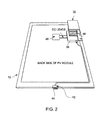
FIG. 2 a rear schematic view showing a dc-to-ac microinverter integral to the PV laminate and a plug and play ac-voltage power connector suitable for use with the system shown inFIG. 1 to carry an equipment ground connection from ac-voltage module to ac-voltage module through the plurality of ac-voltage modules; -
FIG. 3 is a front perspective view of a PV mounting system with a single row of a basic building block of PV modules that form a single circuit and held in place with metallic rails that are grounded using metallic grounding bars according to an embodiment of the invention; -
FIG. 4 is a front perspective view of a PV mounting system that includes two rows of the basic building blocks of PV modules with mounting rails that are automatically grounded using metallic grounding bars according to an embodiment of the invention; -
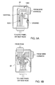
FIGS. 5(a) and 5(b) are schematic views of a standard connector box and a pass-through connector box, respectively, according to an embodiment of the invention. - While the above-identified drawing figures set forth alternative embodiments, other embodiments of the present invention are also contemplated, as noted in the discussion. In all cases, this disclosure presents illustrated embodiments of the present invention by way of representation and not limitation. Numerous other modifications and embodiments can be devised by those skilled in the art which fall within the scope and principles of this invention.
- Referring now to
FIGS. 1-5 , a photovoltaic (PV)mounting system 10 includes a plurality ofPV modules 12, a plurality ofmetallic rail sections 14, a plurality ofmetallic grounding bars 16, awiring harness 18, alocking cover 20 for covering and protecting thewiring harness 18, aconnector box 22, at least onehome run cable 24, and a plurality of mountingstanchions 26 with L-brackets 28 for mounting therails sections 14 to thestanchions 26. In the illustrated embodiment, thePV mounting system 10 includes abasic building block 30 with five (5)PV modules 12. However, it will be appreciated that the invention is not limited by the number ofPV modules 12 that are configured for thebasic building block 30, and that thebasic building block 30 may include any desirable number ofPV modules 12, depending on design requirements and National Electrical Code (NEC) limitations. In one example, eachPV module 12 is an ac module consisting of a low voltage dc module and an integral dc-ac inverter so that eachPV module 12 can produce 240Vac power. In another example, eachPV module 12 can produce 120Vac power. The highest dc voltage is the dc voltage of asingle PV module 12, which is approximately 30V, which is less than the UL safety limit of 48Vdc. The number of PV modules in a single circuit is determined by both the NEC and by the size of the protection circuit breaker in the load panel. - As shown in
FIG. 2 , the backside of eachPV module 12 includes a micro-inverter 32 housed within ametal case 36. Each micro-inverter 32 is integrated with acorresponding PV module 12. EachPV module 12 includes ametallic frame 40 with a plug andplay module connector 42 located on the top of thePV module 12 when thePV module 12 is inserted into the rail sections 14 (FIG. 1 ). The plug andplay module connector 42 may include, for example, four pins 44: a pair of 120V ac-voltage pins, a neutral conductor pin and a dc ground conductor pin. Conversely, thewiring harness 18 may include, for example, a corresponding connector 19 (FIG. 1 ) with fourslots 21 for receiving the four pins 44: a pair of 120V ac-voltage slots, a neutral conductor slot and a dc ground conductor slot. Each plug andplay module connector 42 is electrically connected internal to its corresponding micro-inverter 32 to a respective micro-inverter chassis/ground, which may be, for example, themicro-inverter metal case 36. Themetal case 36 of each micro-inverter 32 is mechanically and electrically attached to themetallic frame 40 of acorresponding PV module 12 by a metallicframe attachment bracket 46, for example, to form a low resistance grounding contact between themetal case 36 and the correspondingmetallic frame 40. It will be appreciated that the invention is not limited by the plug andplay module connector 42 havingpins 44 that cooperate with respective slots of thewiring harness 18, and that the invention can be practiced with the plug andplay module connector 42 having slots that receive respective pins of thewiring harness 18. In other words, the pins and slots can be located on eitherconnector connector 42 is also not a limitation because theconnector 42 could be located at the back of thePV module 12 in a manner that does not compromise the physical insertion of thePV module 12 into the "insert and capture"rail sections 14. - Presently, all commercial systems that employ micro-inverters 32 still require an equipment ground, meaning that all modules with
metallic frames 40 and metal mounting systems have to be connected to a common earth ground through a low resistance path. Such inter-module ground connections are still made using processes that require the use of metallic splices, lugs, penetrating washers, and wires. All of these methods require hands-on grounding connections be made at the time of installation and usually requires the presence of an experience electrician. - Each micro-inverter 32 may be connected to the
PV module 12 through acorresponding junction box 48. Eachjunction box 48 houses the normal +/- dc wiring/connectors of aPV module 12 and the corresponding micro-inverter 32. Because eachmicro-inverter case 36 is also electrically coupled to themetallic frame 40 of itscorresponding PV module 12, the ground pin in each of theconnectors module frames 40 that are interconnected through theconnectors - The
connectors PV module 12 toPV module 12 of thebasic building block 30 of thePV mounting system 10. Because eachmicro-inverter case 36 is electrically coupled to themetallic frame 40 of itscorresponding PV module 12, the ground pins in thepower connectors module frames 40 when all of thePV modules 12 are installed into themetallic rail sections 14. Further, themetallic grounding bars 16 connected to each end of themetallic rail sections 14 serve to provide a continuous grounding path between themetallic rail sections 14. Further, pre-drilled holes in the ends of therail sections 14 for mounting themetallic grounding bars 16 ensure the correct spacing between the pair ofrail sections 14 of thebasic building block 30, as shown inFIG. 1 . - The number of
basic building blocks 30 that form a single circuit of thePV mounting system 10 depends on the amount of electrical power generated by eachPV module 12. To this end, the invention can be practiced with any desirable number ofbasic building blocks 30 andPV modules 12, depending on the amount of electrical power generated by eachPV module 12, the limitation of the electrical load panel according to NEC limitations, and the rating of the protection circuit breaker in the load panel. It is noted that each micro-inverter 34 produces ∼1A of current and the circuit breaker rating is 15-20A, which constitutes a single circuit. More power can be accommodated by the load panel, but will require an additional breaker, circuit andhome run cable 24. In one example, abasic building block 30 comprising a single row, R1, of five (5)PV modules 12 forms a single circuit, C1, as shown inFIGS. 1 and3 . In this example, thePV mounting system 10 includes a pair ofmetallic rail sections 14, a pair ofmetallic grounding bars 16, awiring harness 18, alocking cover 20 for covering and protecting thewiring harness 18, aconnector box 22, ahome run cable 24, and a plurality ofmounting stanchions 26 with L-brackets 28 for mounting therails sections 14 to thestanchions 26. - One end of the
wire harness 18 is connected to aconnector box 22. Thehome run cable 24 from theconnector box 22 produces a single circuit, C1, with about 5A of electrical current (for five (5) PV modules), which can be fed to a conventional 15A circuit breaker panel (not shown). Because eachPV module 12 generates about 1A of electrical current, a total of about 10-13PV modules 12 on a single circuit, C1, can be fed to a conventional 15A circuit breaker panel, depending on the amount of electrical current that is generated by eachPV module 12. It will be appreciated that theconnector 56 can be fed to another row of PV modules, and so on, until the last row of PV modules are fed to the circuit breaker panel. A system having more than about 10-13PV modules 12 will need an additionalhome run cable 24 and circuit breaker. It is noted that the ground pin from theconnectors 19, 42 (not visible inFIG. 3 ) is grounded to the metal wall of theconnector box 22, and theconnector box 22 is electrically connected to themetallic rail section 14 by using a metallic connector, such as a screw, washer, and the like. Thus, theground bar 16 automatically grounds theconnectors metallic rail sections 14. - Because the
PV mounting system 10 requires the capture of the top and bottom of eachPV module 12 in therail sections 14, the spacing between themetallic rail sections 14 is important. One aspect of the invention is that therails sections 14 include a plurality of pre-drilled holes for mounting the metallic grounding bars 16 at the proper location and ensuring the correct spacing between the pair ofrail sections 14, thereby reducing installation errors. Therefore, the metallic grounding bars 16 serve a dual purpose: 1) to ensure correct physical spacing between themetallic rail sections 14; and 2) to automatically ground themetallic rail sections 14 andconnectors - As shown in
FIGS. 4 and5 , twobasic building blocks 30 with five (5)PV modules 12 in eachbasic building block 30 forming two rows R1, R2 are joined together with a common centermetallic rail section 14. Ametallic rail section 14 is also at each end of thePV mounting system 10. A total of four side ground bars 16 at each end of the rows R1, R2 ofbasic building blocks 30 ground all threemetallic rail sections 14. - One end of the
wire harness 18 is connected to astandard connector box 22. Aconnector 54 from thestandard connector box 22 is, in turn, connected to a pass-through connector box 22'. In the illustrated example, aconnector 56 from the pass-through connector box 22' produces a single circuit, C1, with about 10 amps of electrical power, which can be fed to a conventional 15 amp circuit breaker panel (not shown). It will be appreciated that theconnector 54 can be directly fed to the circuit breaker panel if there is only one row of up to about 10-13PV modules 12, similar to the example ofFIG. 3 . It will also be appreciated that theconnector 56 can be fed to another row of PV modules, and so on, until the last row of PV modules are fed to the circuit breaker panel. A system having more than about 10-13PV modules 12 will need an additionalhome run cable 24 and circuit breaker. It is noted that the ground pin from theconnectors connector boxex 22, 22', and theconnector boxes 22, 22', in turn, are electrically connected to themetallic rail section 14 by using a metallic connector, such as a screw, washer, and the like. Thus, theground bar 16 grounds theconnectors metallic rail sections 14. - While only certain features of the invention have been illustrated and described herein, many modifications and changes will occur to those skilled in the art. It is, therefore, to be understood that the appended claims are intended to cover all such modifications and changes as fall within the scope of the invention as defined in the appended claims.
Claims (10)
- A system for grounding photovoltaic (PV) modules comprising at least one building block (30) including at least one PV module (12), a pair of metallic rail sections (14), and a metallic grounding bar (16) connected to each end of the metallic rail sections (14) for grounding the metallic rail sections (14).
- The system according to claim 1, further comprsing at least one dc-ac micro-inverter (32).
- The system according to claim 2, wherein the at least one micro-inverter (32) is internally connected to a respective chassis ground or metal case (36) and integrated with the at least one PV module (12).
- The system according to claim 1, 2 or 3, wherein the at least one PV module (12) includes a connector (42), and wherein the system further includes a wiring harness with a connector (19) that mates with the connector (42) of the at least one PV module (12).
- The system according to claim 4, wherein each connector (19, 42) includes a ground pin that is electrically connected to a metal case (36) of a micro-inverter (32).
- The system according to claim 5, wherein the metal case (36) is mechanically and electrically attached to the metallic frame (40) of the at least one PV module 12 by a metallic frame attachment bracket (46).
- The system according to any one of claims 1 to 6, further comprising a wiring harness (18) for electrically connecting the at least one PV module (12) to a standard connector box (22), a locking cover (20) for covering and protecting the ac wiring harness (18), and a home run cable (24) electrically connected to the standard connector box (22) to provide a single circuit, C1.
- The system according to any one of claims 1 to 7, further comprising a plurality of PV modules in a first row, R1, and a plurality of PV modules in a second row, R2, wherein the plurality of PV modules in the first row, R1, are connected standard connector box (22), and wherein a connector (54) from the connector box (22) and the plurality of PV modules (12) in the second row, R2, are connected to a pass-through connector box (22'), and a connector (56) electrically connected to the pass-through connector box (22') to provide a single circuit, C1, from the pass-through connector box (22').
- A method for grounding a photovoltaic system (10), comprising:inserting a PV module (12) into a first metallic rail section (14) and into a second, opposite metallic rail section (14) to hold the PV module (12) in place; and
connecting a grounding bar (16) to each end of the first and second metallic rail sections (14) for grounding the metallic rail sections (14). - The method of claim 9, further comprising electrically connecting the PV module (12) to a wiring harness (18), electrically connecting the wiring harness (18) to a standard connector box (22), and electrically connecting a connector (24) to the standard connector box (22) to provide a single circuit, C1.
Applications Claiming Priority (1)
| Application Number | Priority Date | Filing Date | Title |
|---|---|---|---|
| US13/079,900 US20120255596A1 (en) | 2011-04-05 | 2011-04-05 | Photovoltaic mounting system with grounding bars and method of installing same |
Publications (2)
| Publication Number | Publication Date |
|---|---|
| EP2509114A2 true EP2509114A2 (en) | 2012-10-10 |
| EP2509114A3 EP2509114A3 (en) | 2013-11-27 |
Family
ID=46044364
Family Applications (1)
| Application Number | Title | Priority Date | Filing Date |
|---|---|---|---|
| EP12162882.0A Withdrawn EP2509114A3 (en) | 2011-04-05 | 2012-04-02 | Photovoltaic mounting system with grounding bars and method of installing same |
Country Status (4)
| Country | Link |
|---|---|
| US (2) | US20120255596A1 (en) |
| EP (1) | EP2509114A3 (en) |
| CN (1) | CN102810587A (en) |
| AU (1) | AU2012201959A1 (en) |
Cited By (2)
| Publication number | Priority date | Publication date | Assignee | Title |
|---|---|---|---|---|
| WO2014189930A1 (en) * | 2013-05-21 | 2014-11-27 | Sunedison Llc | Alternating current photovoltaic modules |
| EP3075218A4 (en) * | 2013-11-27 | 2016-12-07 | Phillip C Gilchrist | INTEGRATION OF A MICRO-INVERTER TO A PHOTOVOLTAIC MODULE |
Families Citing this family (18)
| Publication number | Priority date | Publication date | Assignee | Title |
|---|---|---|---|---|
| US8595996B2 (en) * | 2010-02-26 | 2013-12-03 | General Electric Company | Photovoltaic framed module array mount utilizing asymmetric rail |
| US20120255596A1 (en) * | 2011-04-05 | 2012-10-11 | General Electric Company | Photovoltaic mounting system with grounding bars and method of installing same |
| US9373959B2 (en) | 2011-06-21 | 2016-06-21 | Lg Electronics Inc. | Photovoltaic module |
| US9837556B2 (en) * | 2011-10-31 | 2017-12-05 | Volterra Semiconductor LLC | Integrated photovoltaic panel with sectional maximum power point tracking |
| TWI425646B (en) * | 2012-01-06 | 2014-02-01 | Au Optronics Corp | Frame element of photovoltaic device, the photovoltaic device and photovoltaic array system having the photovoltaic device |
| CN102610674B (en) * | 2012-03-05 | 2014-03-26 | 友达光电股份有限公司 | Components for fixing solar module wires and solar modules using it |
| US9343600B2 (en) * | 2013-12-06 | 2016-05-17 | Haibo Zhang | Integrated microinverter housing for a PV AC module |
| EP3090483A4 (en) * | 2013-12-31 | 2017-03-22 | Marco A. Marroquin | Alternating current photovoltaic module |
| US20150280439A1 (en) * | 2014-03-26 | 2015-10-01 | Enphase Energy, Inc. | Apparatus for grounding interconnected electrical components and assemblies |
| JP2015223012A (en) * | 2014-05-22 | 2015-12-10 | 株式会社豊田自動織機 | Solar cell module |
| US9584062B2 (en) | 2014-10-16 | 2017-02-28 | Unirac Inc. | Apparatus for mounting photovoltaic modules |
| DE202015000200U1 (en) * | 2015-01-16 | 2015-02-18 | Sigma Energy Systems Gmbh | Solar roof panel system |
| US10069457B2 (en) * | 2015-05-20 | 2018-09-04 | General Electric Company | System for mounting a microinverter to a photovoltaic panel and method of making same |
| US10164566B2 (en) * | 2015-05-20 | 2018-12-25 | General Electric Company | Universal microinverter mounting bracket for a photovoltaic panel and associated method |
| WO2017109871A1 (en) * | 2015-12-24 | 2017-06-29 | 株式会社 東芝 | Solar power generation system and supporting device for solar power generation apparatus |
| KR101916423B1 (en) * | 2016-10-11 | 2018-11-07 | 엘지전자 주식회사 | Solar cell module |
| WO2018224701A1 (en) * | 2017-06-08 | 2018-12-13 | Aaag Seros Training, S.L. | Assembly system for photovoltaic plants |
| CN114991396B (en) * | 2022-06-10 | 2024-09-13 | 中建八局南方建设有限公司 | Solar photovoltaic steel structure lightning protection roof and construction method thereof |
Family Cites Families (8)
| Publication number | Priority date | Publication date | Assignee | Title |
|---|---|---|---|---|
| US20100108118A1 (en) * | 2008-06-02 | 2010-05-06 | Daniel Luch | Photovoltaic power farm structure and installation |
| WO2008028151A2 (en) * | 2006-08-31 | 2008-03-06 | Pvt Solar, Inc. | Technique for electrically bonding solar modules and mounting assemblies |
| US20100236610A1 (en) * | 2007-09-03 | 2010-09-23 | Robert Stancel | Mounting System for Solar Modules |
| US8813460B2 (en) * | 2007-09-21 | 2014-08-26 | Andalay Solar, Inc. | Mounting system for solar panels |
| US20100275977A1 (en) * | 2007-12-21 | 2010-11-04 | E. I. Du Pont De Nemours And Company | Photovoltaic array and methods |
| US8661765B2 (en) * | 2009-02-05 | 2014-03-04 | D Three Enterprises, Llc | Interlocking shape for use in construction members |
| WO2010144637A1 (en) * | 2009-06-10 | 2010-12-16 | Solar Infra, Inc. | Integrated solar photovoltaic ac module |
| US20120255596A1 (en) * | 2011-04-05 | 2012-10-11 | General Electric Company | Photovoltaic mounting system with grounding bars and method of installing same |
-
2011
- 2011-04-05 US US13/079,900 patent/US20120255596A1/en not_active Abandoned
-
2012
- 2012-04-02 EP EP12162882.0A patent/EP2509114A3/en not_active Withdrawn
- 2012-04-04 AU AU2012201959A patent/AU2012201959A1/en not_active Abandoned
- 2012-04-05 CN CN201210178861XA patent/CN102810587A/en active Pending
-
2014
- 2014-04-11 US US14/250,982 patent/US20140216530A1/en not_active Abandoned
Non-Patent Citations (1)
| Title |
|---|
| None |
Cited By (3)
| Publication number | Priority date | Publication date | Assignee | Title |
|---|---|---|---|---|
| WO2014189930A1 (en) * | 2013-05-21 | 2014-11-27 | Sunedison Llc | Alternating current photovoltaic modules |
| GB2529350A (en) * | 2013-05-21 | 2016-02-17 | Sunedison Inc | Alternating current photovoltaic modules |
| EP3075218A4 (en) * | 2013-11-27 | 2016-12-07 | Phillip C Gilchrist | INTEGRATION OF A MICRO-INVERTER TO A PHOTOVOLTAIC MODULE |
Also Published As
| Publication number | Publication date |
|---|---|
| AU2012201959A1 (en) | 2012-10-25 |
| US20120255596A1 (en) | 2012-10-11 |
| US20140216530A1 (en) | 2014-08-07 |
| CN102810587A (en) | 2012-12-05 |
| EP2509114A3 (en) | 2013-11-27 |
Similar Documents
| Publication | Publication Date | Title |
|---|---|---|
| EP2509114A2 (en) | Photovoltaic mounting system with grounding bars and method of installing same | |
| EP2413382B1 (en) | Integral AC module grounding system | |
| US20140007926A1 (en) | Photovoltaic grounding system and method of making same | |
| US10812015B2 (en) | Micro-inverter assembly for use in a photovoltaic system and method of making same | |
| US20040147172A1 (en) | Apparatus, system, and method of electrically coupling photovoltaic modules | |
| EP2557602A2 (en) | Integral Module Power Conditioning System | |
| JP5678240B2 (en) | Terminal unit having composite / distribution busbar assembly with fuse | |
| EP2584615A1 (en) | Combiner box | |
| CN101796700B (en) | Panelboard | |
| US9466961B2 (en) | Generator connection box for photovoltaic installations | |
| US20160149536A1 (en) | Solar Power Panels, Arrays and Connection Systems | |
| CN107864685A (en) | General Photovoltaic Laminates | |
| HU223704B1 (en) | Upgradable functional feeder unit of a low-voltage electrical cubicle | |
| US9615470B2 (en) | Wiring combiner box | |
| RU113080U1 (en) | MOUNTING RAILS AND ELECTRICAL DISTRIBUTION MODULE CONTAINING THE MENTIONS | |
| US9893678B2 (en) | Photovoltaic system with improved AC connections and method of making same | |
| US20150280439A1 (en) | Apparatus for grounding interconnected electrical components and assemblies | |
| EP2693576B1 (en) | Electric power base and electric power gateway | |
| US20120312354A1 (en) | Solar module and photovoltaic array | |
| KR101615602B1 (en) | Secondary connector of bucket of distribution panel | |
| JP2013038338A (en) | Conductive member for solar cell module and photovoltaic power generation system | |
| JP4983640B2 (en) | Low voltage distribution equipment | |
| CN219144536U (en) | Rail type plug socket structure | |
| RU86055U1 (en) | CABINET FOR CROSS-COUPLING AUTOMATION AND TELEMECHANICS CHAINS IN RAILWAY STATIONS | |
| WO2014204398A1 (en) | An ac solar module |
Legal Events
| Date | Code | Title | Description |
|---|---|---|---|
| PUAI | Public reference made under article 153(3) epc to a published international application that has entered the european phase |
Free format text: ORIGINAL CODE: 0009012 |
|
| AK | Designated contracting states |
Kind code of ref document: A2 Designated state(s): AL AT BE BG CH CY CZ DE DK EE ES FI FR GB GR HR HU IE IS IT LI LT LU LV MC MK MT NL NO PL PT RO RS SE SI SK SM TR |
|
| AX | Request for extension of the european patent |
Extension state: BA ME |
|
| PUAL | Search report despatched |
Free format text: ORIGINAL CODE: 0009013 |
|
| RIC1 | Information provided on ipc code assigned before grant |
Ipc: F24J 2/52 20060101ALI20131010BHEP Ipc: H01R 4/64 20060101ALI20131010BHEP Ipc: H01L 31/042 20060101AFI20131010BHEP |
|
| AK | Designated contracting states |
Kind code of ref document: A3 Designated state(s): AL AT BE BG CH CY CZ DE DK EE ES FI FR GB GR HR HU IE IS IT LI LT LU LV MC MK MT NL NO PL PT RO RS SE SI SK SM TR |
|
| AX | Request for extension of the european patent |
Extension state: BA ME |
|
| RIC1 | Information provided on ipc code assigned before grant |
Ipc: F24J 2/52 20060101ALI20131021BHEP Ipc: H01L 31/042 20060101AFI20131021BHEP Ipc: H01R 4/64 20060101ALI20131021BHEP |
|
| 17P | Request for examination filed |
Effective date: 20140527 |
|
| RBV | Designated contracting states (corrected) |
Designated state(s): AL AT BE BG CH CY CZ DE DK EE ES FI FR GB GR HR HU IE IS IT LI LT LU LV MC MK MT NL NO PL PT RO RS SE SI SK SM TR |
|
| GRAP | Despatch of communication of intention to grant a patent |
Free format text: ORIGINAL CODE: EPIDOSNIGR1 |
|
| RIC1 | Information provided on ipc code assigned before grant |
Ipc: H02S 40/34 20140101ALI20160209BHEP Ipc: F24J 2/52 20060101ALI20160209BHEP Ipc: H02S 20/23 20140101ALI20160209BHEP Ipc: H01R 4/64 20060101ALI20160209BHEP Ipc: H02S 30/10 20140101AFI20160209BHEP |
|
| INTG | Intention to grant announced |
Effective date: 20160223 |
|
| STAA | Information on the status of an ep patent application or granted ep patent |
Free format text: STATUS: THE APPLICATION IS DEEMED TO BE WITHDRAWN |
|
| 18D | Application deemed to be withdrawn |
Effective date: 20160705 |