JP4983640B2 - Low voltage distribution equipment - Google Patents
Low voltage distribution equipment Download PDFInfo
- Publication number
- JP4983640B2 JP4983640B2 JP2008034461A JP2008034461A JP4983640B2 JP 4983640 B2 JP4983640 B2 JP 4983640B2 JP 2008034461 A JP2008034461 A JP 2008034461A JP 2008034461 A JP2008034461 A JP 2008034461A JP 4983640 B2 JP4983640 B2 JP 4983640B2
- Authority
- JP
- Japan
- Prior art keywords
- parallel
- switch
- support
- band
- attached
- Prior art date
- Legal status (The legal status is an assumption and is not a legal conclusion. Google has not performed a legal analysis and makes no representation as to the accuracy of the status listed.)
- Active
Links
Images


Description
この発明は、室内に設けられる低圧配電設備に関し、詳しくは配電に欠かせない配線用遮断器など開閉器の主母線への取付工期短縮のための取付手段における、その主母線の配設に関するものである。 TECHNICAL FIELD The present invention relates to a low-voltage power distribution facility provided indoors, and more particularly to the disposition of the main bus in a mounting means for shortening the installation period of the switch to the main bus such as a circuit breaker essential for power distribution. It is.
電路の開閉、あるいは電路の遮断が行われる回路遮断器など開閉器は、その電路に配設されることから、言うまでもなく、その入力端子(一般に電源側と呼ばれる)および出力端子(一般に負荷側と呼ばれる)に対し配線作業が行われる。ここで、出力端子は不特定の負荷に対して接続されることから、一般にその開閉器が配設された、例えば分電盤を現地に設置後、接続作業がなされることになるが、入力端子については、その盤内において、接続先が例えば主幹バーなどの主母線、といった具合に決まっているため、分電盤の製作過程において、接続作業がなされることになる。ここで、配設される開閉器が一台であれば、さほど問題にはならないが、上述した分電盤のように、多数の負荷機器への給電がなされるように構成されたものにおいては、この入力端子へのネジ締めに多大な工数が掛かることが容易に予想される。 Needless to say, a circuit breaker such as a circuit breaker that opens and closes an electric circuit or that interrupts the electric circuit is disposed in the electric circuit. Wiring work is performed. Here, since the output terminal is connected to an unspecified load, the switch is generally arranged, for example, after the distribution board is installed in the field, the connection work will be done. Since the connection destination of the terminals is determined in the panel such as a main bus such as a main bar, the connection work is performed in the manufacturing process of the distribution board. Here, if only one switch is provided, it will not be a problem. However, in the case where the power is supplied to a large number of load devices like the distribution board described above. Therefore, it is easily expected that a lot of man-hours will be required for screwing the input terminal.
そこで、開閉器の電源側を受刃状のプラグとし、このプラグを等間隔に配設された主幹バーに挿入させることで、入力端子の接続作業が完了し、以って、分電盤の製作工数を短縮せしめることが広く知られている(例えば、特許文献1参照)。 Therefore, the power supply side of the switch is a receiving blade-like plug, and this plug is inserted into the main bar arranged at equal intervals, so that the connection work of the input terminal is completed. It is widely known to shorten the number of manufacturing steps (for example, see Patent Document 1).
この特許文献1で開示されている開閉器は、比較的小さな電流(30A程度)で駆動あるいは消費される機器への接続を想定しており、また、極間電圧も100Vクラスであることから、主幹バーはプラグとの接触面が相対向するように配設されている。一方、極間電圧が400Vクラスで、しかも100〜600Aといった、比較的大きな電流では、極間距離および接触通電能力の確保の点から、特許文献1の適用は困難である。そこで、開閉器の底面に、該開閉器の電源側に接続される、やはり受刃状のプラグを備えた差込端子部を付加し、このプラグを、該開閉器の入力端子と出力端子とを結ぶ長手方向と直交するように等間隔に配設された主母線に挿入させることも知られている(例えば、特許文献2参照)。なお、この方式が採用される盤は、一般に受配電盤と呼ばれているが、本明細書においては、この「配電」部分を「低圧配電設備」と、また、「主母線」を「平行導帯」と、これ以降、それぞれ呼称することとする。 The switch disclosed in Patent Document 1 is assumed to be connected to a device that is driven or consumed with a relatively small current (about 30 A). The main bar is arranged so that the contact surfaces with the plugs face each other. On the other hand, when the voltage between the electrodes is 400 V class and the current is relatively large such as 100 to 600 A, it is difficult to apply Patent Document 1 from the viewpoint of securing the distance between the electrodes and the contact energization capability. Therefore, an insertion terminal portion having a receiving blade-like plug connected to the power source side of the switch is added to the bottom surface of the switch, and the plug is connected to the input terminal and the output terminal of the switch. It is also known that it is inserted into main buses arranged at equal intervals so as to be orthogonal to the longitudinal direction connecting the two (see, for example, Patent Document 2). Panels adopting this method are generally called power distribution boards. In this specification, the “distribution” part is referred to as “low-voltage distribution equipment” and the “main bus” is referred to as “parallel conductor”. The band is hereinafter referred to as “band”.
この特許文献2の方式においては、平行導帯のピッチに合致するよう、差込端子部にプラグが装着されていることから、自ずと平行導帯のピッチは正しく確保されていないと、開閉器の挿入作業に支障を来たしてしまう。ところが、図6からも明らかなように、平行導帯は樹脂製の取付台にボルト締めされているため、このボルト締めによる締め付け推力によって圧縮歪を生じさせ、ピッチが狂う恐れがあった。特に、平行導帯の幅方向(すなわちプラグとの接触面)が広い1600Aクラスでは、ボルトが平行導帯の一方の端部に位置することによる、ボルトと他方の端部との距離が比較的長くなることで、他方の端部(すなわちプラグとの接触面側、図7(b)参照)でのピッチずれが顕著に現れることになる。
In the method of this
また、折角、開閉器の入力端子の接続をプラグ挿入にして、その工数を低減させても、上述したように、平行導帯のボルト締めが残ってしまうことで、この作業工数の点においてもまだまだ改善の余地があった。 In addition, even if the connection of the input terminal of the breaker and the switch is inserted into the plug and the man-hour is reduced, as described above, the bolting of the parallel conductive band remains, so in terms of this man-hour. There was still room for improvement.
この発明は、上述のような課題を解決するためになされたもので、平行導帯の極間ピッチを適切に保てる低圧配電設備を得ることを目的とするものである。 The present invention has been made to solve the above-described problems, and an object of the present invention is to obtain a low-voltage power distribution facility that can appropriately maintain the inter-electrode pitch of the parallel conductive bands.
開閉器の入力端子と出力端子とを結ぶ長手方向と直交するように配設され、上記入力端子と電気的に接続される平行導帯と、上記低圧配電設備を形成する支柱部材などに並設されて取り付けられ、上記平行導帯を支持する樹脂製の複数の支持台とを備えた低圧配電設備において、上記平行導帯の上記支持台への支持が、上記平行導帯の両側面より上記長手方向と平行に延在する凸部と、この凸部と係合する上記支持台の凹部が嵌め合わされることで行われるとともに、上記複数の支持台のうち、少なくとも一組は、上記凹部が相対向するように取り付けられるようにしたものである。
Is arranged perpendicular to the longitudinal direction connecting the input terminal of the switch and an output terminal, and parallel gubernaculum which are electrically connected to the input terminal, arranged like strut member to form the low-voltage distribution facilities In the low-voltage power distribution facility provided with a plurality of resin-made support bases that are attached and support the parallel conductive bands, the parallel conductive bands are supported on the support bases from both side surfaces of the parallel conductive bands. It is performed by fitting a convex portion extending in parallel with the longitudinal direction and a concave portion of the support base that engages with the convex portion, and at least one set of the plurality of support bases includes the concave portion. It is designed to be attached so as to face each other.
この発明は以上説明したように、製造コストを低減させた、給電信頼性の高い低圧配電設備を提供することが可能となる。 As described above, according to the present invention, it is possible to provide a low-voltage distribution facility with reduced powering reliability and high power supply reliability.
実施の形態1.
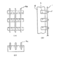
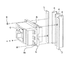
図1はこの発明の実施の形態1における低圧配電設備のうち、要部となる平行導帯と支持台の嵌め合いを示す図であり、(a)は正面図、(b)は右側面図、(c)は下面図である。また、図2および図3は、平行導帯および支持台の、それぞれ斜視図である。なお、図4は、低圧配電設備への開閉器の取り付けを示す斜視図である。
Embodiment 1 FIG.
1A and 1B are diagrams showing the fitting of a parallel conductive band and a support base, which are main parts, in a low-voltage distribution facility according to Embodiment 1 of the present invention. FIG. 1A is a front view, and FIG. (C) is a bottom view. 2 and 3 are perspective views of the parallel conducting band and the support base, respectively. FIG. 4 is a perspective view showing the attachment of the switch to the low-voltage distribution facility.
図4において、図示しない低圧配電設備の内部に平行導帯4が3本並設されているとともに、一般にアングルと呼ばれる取付パネル5が縦横に張り巡らされている。この取付パネル5に取付用の孔を設け、後述するさし込式開閉器を設置することになる。なお、平行導帯4が3本であることから、この実施の形態1では、三相三線、あるいは単相三線を想定しているが、これに限定される訳ではなく、2本もしくは4本であってもよい。
In FIG. 4, three parallel conducting
さし込式開閉器6は開閉器7と端子台8とで構成されており、開閉器7の図示しない電源側端子が、端子台8に装着された、やはり図示しないプラグに電気的に接続されている。すなわち、上述したように、さし込式開閉器6を取付パネル5に設置すれば、プラグが平行導帯4に挿入され、さらに、締付ネジ9でさし込式開閉器6を取付パネル5に取り付けることで、いわゆる入力端子における電気的接続が完了となる。また、出力端子、すなわち、負荷側端子10は、その形状が示すように、通常の電線、もしくはバーを図示しないネジで締め付ける接続が行われることになる。なお、言うまでもなく、本発明の本質は上述した平行導帯4の並設を如何に行ったかにあり、平行導帯4とさし込式開閉器6の電気的接続などは本発明の要部ではないため、これ以上の詳しい説明は省略する。
The insertion type switch 6 includes a switch 7 and a terminal block 8, and a power supply side terminal (not shown) of the switch 7 is electrically connected to a plug (not shown) mounted on the terminal block 8. Has been. That is, as described above, if the insertion type switch 6 is installed on the
図1において、平行導帯4は、低圧配電設備の筐体1に取付ネジ2にて取り付けられた支持台3によって支持されている。ここで、平行導帯4は、図2に示すように、端子台8のプラグと干渉しない位置に、プラグと接触する面から両方向(紙面上、左右方向)に延在した凸部4aを備えている。なお、この凸部4aは、平行導帯に貫通孔を設け、この貫通孔に丸棒を圧入することが、製造コスト上からも好ましい。
In FIG. 1, the parallel conducting
一方、支持台3は平行導帯4同士の絶縁を図るため樹脂で形成され、図3に示すように、この平行導帯4が挿入される溝3aと、この溝3aと直交する凹部3bを備えている。なお、3cは、取付ネジ2が螺着されるネジ穴である。また、溝3aおよび凹部3bは、上述と同様、この図3で示す3個には限定されず、4個であってもよい。この支持台3を、図1(a)に示すように、所定のピッチ(=凸部4aのピッチ)にて、取付ネジ2により取り付けていくが、このとき、紙面上、上部に位置する支持台3はまだ取り付けは行わない。なお、このピッチは、図では等間隔で示しているが、必ずしも、これに限定される訳ではない。
On the other hand, the
そして、各支持台3の図1(a)紙面上、上部に凸部4aがくるように、平行導帯4のプラグと接触する面を溝3aに挿入した後、凸部4aを凹部3bに嵌め合わせる。これにより、紙面上、左右方向および下方向への平行導帯4の移動が制限される。さらに、上部に位置させるべく支持台3を、最頂部4bより溝3aをいわゆるレール状に下方向へ移動させ、凸部4aと凹部3bが嵌め合わされた時点で、取付ネジ2により、他の支持台3と同様、筐体1に取り付けることで、低圧配電設備として形成されることになる。
And after inserting the surface which contacts the plug of the parallel conducting
この構成により、平行導帯4はボルトなどでの締結が行われないため、平行導帯4の天面4cでの極間ピッチが適切に保たれることになり、より給電の信頼性が向上する。また、上部に位置する支持台3を、図1(a)(b)でも明らかなように、平行導帯4を挿入する前に取り付ける支持台3との、その取り付け向きを変えているので、上述した左右および下方向に加え、上方向、すなわち全方向に対して平行導帯4を保持させることが可能となっている。
With this configuration, since the
さらに、言うまでもなく、平行導帯4のボルト締結作業を廃したので、その組立工数削減が期待できる。特に、開閉器(回路遮断器)の遮断容量をアップさせたような盤では、その遮断容量に応じた通過電流における平行導帯間での電磁反発力に耐え得るために、本発明や特許文献2で示した3個の支持台(取付台)ではなく、例えば5個以上に及ぶ可能性があるため、この波及効果は大きい。
Furthermore, needless to say, since the bolt fastening operation of the
3 支持台、3a 溝、3b 凹部、4 平行導帯、4a 凸部、4b 最頂部、
6 さし込式開閉器、 7 開閉器、 8 端子台。
3 support base, 3a groove, 3b concave portion, 4 parallel guide band, 4a convex portion, 4b topmost portion,
6 insert type switch, 7 switch, 8 terminal block.
Claims (1)
上記平行導帯の上記支持台への支持が、上記平行導帯の両側面より上記長手方向と平行に延在する凸部と、この凸部と係合する上記支持台の凹部が嵌め合わされることで行われるとともに、上記複数の支持台のうち、少なくとも一組は、上記凹部が相対向するように取り付けられていることを特徴とする低圧配電設備。 A low-voltage distribution facility to which a switch such as a circuit breaker is attached, which is arranged so as to be orthogonal to the longitudinal direction connecting the input terminal and the output terminal of the switch and is electrically connected to the input terminal. A conductive band, and a plurality of resin-made support bases that are mounted side by side and attached to a column member that forms the low-voltage power distribution facility, and that support the parallel conductive band;
The parallel conductive band is supported on the support base by fitting a convex portion extending in parallel with the longitudinal direction from both side surfaces of the parallel conductive band and a concave portion of the support base engaging with the convex portion. And at least one set of the plurality of support bases is attached so that the recesses face each other .
Priority Applications (2)
| Application Number | Priority Date | Filing Date | Title |
|---|---|---|---|
| JP2008034461A JP4983640B2 (en) | 2008-02-15 | 2008-02-15 | Low voltage distribution equipment |
| CN2008100981030A CN101510670B (en) | 2008-02-15 | 2008-05-07 | Low-voltage distribution apparatus |
Applications Claiming Priority (1)
| Application Number | Priority Date | Filing Date | Title |
|---|---|---|---|
| JP2008034461A JP4983640B2 (en) | 2008-02-15 | 2008-02-15 | Low voltage distribution equipment |
Publications (2)
| Publication Number | Publication Date |
|---|---|
| JP2009195052A JP2009195052A (en) | 2009-08-27 |
| JP4983640B2 true JP4983640B2 (en) | 2012-07-25 |
Family
ID=41002963
Family Applications (1)
| Application Number | Title | Priority Date | Filing Date |
|---|---|---|---|
| JP2008034461A Active JP4983640B2 (en) | 2008-02-15 | 2008-02-15 | Low voltage distribution equipment |
Country Status (2)
| Country | Link |
|---|---|
| JP (1) | JP4983640B2 (en) |
| CN (1) | CN101510670B (en) |
Families Citing this family (1)
| Publication number | Priority date | Publication date | Assignee | Title |
|---|---|---|---|---|
| CN110133955A (en) * | 2019-05-14 | 2019-08-16 | 西安电子科技大学 | A kind of projection device applied in telecommunications field |
Family Cites Families (10)
| Publication number | Priority date | Publication date | Assignee | Title |
|---|---|---|---|---|
| JPS437101Y1 (en) * | 1965-08-11 | 1968-03-29 | ||
| JPS4829397U (en) * | 1971-08-12 | 1973-04-11 | ||
| JPS4895198U (en) * | 1972-02-08 | 1973-11-13 | ||
| JPS49106897U (en) * | 1973-01-06 | 1974-09-12 | ||
| JPS5543725Y2 (en) * | 1976-02-12 | 1980-10-14 | ||
| JPH03203513A (en) * | 1989-12-28 | 1991-09-05 | Fuji Electric Co Ltd | Bus support in distribution board |
| JPH04185211A (en) * | 1990-11-20 | 1992-07-02 | Toshiba Corp | Conductor support |
| JP3156363B2 (en) * | 1992-04-28 | 2001-04-16 | 株式会社日立製作所 | switchboard |
| DE19511348A1 (en) * | 1995-03-28 | 1996-10-02 | Kloeckner Moeller Gmbh | Insert element of a low-voltage switchgear |
| CN2930031Y (en) * | 2006-04-12 | 2007-08-01 | 陈英俊 | Bus for high and low voltage switch cabinet and its connection structure |
-
2008
- 2008-02-15 JP JP2008034461A patent/JP4983640B2/en active Active
- 2008-05-07 CN CN2008100981030A patent/CN101510670B/en active Active
Also Published As
| Publication number | Publication date |
|---|---|
| CN101510670B (en) | 2011-09-28 |
| CN101510670A (en) | 2009-08-19 |
| JP2009195052A (en) | 2009-08-27 |
Similar Documents
| Publication | Publication Date | Title |
|---|---|---|
| KR100910100B1 (en) | Terminal device of electrical apparatus | |
| US8531820B2 (en) | Bus system and module body for use therein | |
| US20140216530A1 (en) | Photovoltaic mounting system with grounding bars and method of installing same | |
| US8684758B2 (en) | Terminal unit having fused combiner/distribution bus bar assembly | |
| KR100543964B1 (en) | Connecting method between main boothbar and sub boothbar and main boothbar and sub boothbar with side connecting structure | |
| CN100585947C (en) | Terminal board component and screwless connector | |
| KR100672960B1 (en) | Apparatus for supporting bus-bar | |
| US10374403B2 (en) | Electrical power distribution box for an aircraft | |
| JP3113266U (en) | Unit distribution board | |
| JP2006238562A (en) | Plug-in distribution board | |
| JP4983640B2 (en) | Low voltage distribution equipment | |
| KR100534589B1 (en) | Between main busbar and sub busbar for an distribution switchboard and connecting apparatus thereof | |
| JP4268782B2 (en) | Distribution board with breaker terminal block and primary feed breaker | |
| JP4544586B2 (en) | Distribution line main bar connection structure | |
| KR100825379B1 (en) | a connecting apparatus for a distributing board | |
| JP2006210199A (en) | Terminal board | |
| KR101326329B1 (en) | Power connection conductor | |
| JP4371362B2 (en) | Terminal cover mounting structure | |
| JP6433336B2 (en) | Distribution board | |
| JP4667970B2 (en) | No-fuse breaker mounting device | |
| KR20060117647A (en) | Connecting method between main busbar and sub busbar for an distribution switchboard and connecting apparatus thereof | |
| KR200322467Y1 (en) | Terminal Plate for Instrument Transformer | |
| JP4177304B2 (en) | Electric junction box terminal block connection structure | |
| HU220263B (en) | Device for connecting electrical-installation apparatuses | |
| KR200449732Y1 (en) | Assembly Plug for the Cabinet Panel |
Legal Events
| Date | Code | Title | Description |
|---|---|---|---|
| A621 | Written request for application examination |
Free format text: JAPANESE INTERMEDIATE CODE: A621 Effective date: 20100601 |
|
| A977 | Report on retrieval |
Free format text: JAPANESE INTERMEDIATE CODE: A971007 Effective date: 20120224 |
|
| A131 | Notification of reasons for refusal |
Free format text: JAPANESE INTERMEDIATE CODE: A131 Effective date: 20120228 |
|
| A521 | Request for written amendment filed |
Free format text: JAPANESE INTERMEDIATE CODE: A523 Effective date: 20120306 |
|
| TRDD | Decision of grant or rejection written | ||
| A01 | Written decision to grant a patent or to grant a registration (utility model) |
Free format text: JAPANESE INTERMEDIATE CODE: A01 Effective date: 20120327 |
|
| A01 | Written decision to grant a patent or to grant a registration (utility model) |
Free format text: JAPANESE INTERMEDIATE CODE: A01 |
|
| A61 | First payment of annual fees (during grant procedure) |
Free format text: JAPANESE INTERMEDIATE CODE: A61 Effective date: 20120409 |
|
| R151 | Written notification of patent or utility model registration |
Ref document number: 4983640 Country of ref document: JP Free format text: JAPANESE INTERMEDIATE CODE: R151 |
|
| FPAY | Renewal fee payment (event date is renewal date of database) |
Free format text: PAYMENT UNTIL: 20150511 Year of fee payment: 3 |
|
| R250 | Receipt of annual fees |
Free format text: JAPANESE INTERMEDIATE CODE: R250 |
|
| R250 | Receipt of annual fees |
Free format text: JAPANESE INTERMEDIATE CODE: R250 |
|
| R250 | Receipt of annual fees |
Free format text: JAPANESE INTERMEDIATE CODE: R250 |
|
| R250 | Receipt of annual fees |
Free format text: JAPANESE INTERMEDIATE CODE: R250 |
|
| R250 | Receipt of annual fees |
Free format text: JAPANESE INTERMEDIATE CODE: R250 |
|
| R250 | Receipt of annual fees |
Free format text: JAPANESE INTERMEDIATE CODE: R250 |
|
| R250 | Receipt of annual fees |
Free format text: JAPANESE INTERMEDIATE CODE: R250 |
|
| R250 | Receipt of annual fees |
Free format text: JAPANESE INTERMEDIATE CODE: R250 |