EP2508861A1 - System and method for determining inertia properties of a rigid body - Google Patents
System and method for determining inertia properties of a rigid body Download PDFInfo
- Publication number
- EP2508861A1 EP2508861A1 EP11168278A EP11168278A EP2508861A1 EP 2508861 A1 EP2508861 A1 EP 2508861A1 EP 11168278 A EP11168278 A EP 11168278A EP 11168278 A EP11168278 A EP 11168278A EP 2508861 A1 EP2508861 A1 EP 2508861A1
- Authority
- EP
- European Patent Office
- Prior art keywords
- rigid body
- carrier
- elastic elements
- properties
- freedom
- Prior art date
- Legal status (The legal status is an assumption and is not a legal conclusion. Google has not performed a legal analysis and makes no representation as to the accuracy of the status listed.)
- Granted
Links
Images
Classifications
-
- G—PHYSICS
- G01—MEASURING; TESTING
- G01M—TESTING STATIC OR DYNAMIC BALANCE OF MACHINES OR STRUCTURES; TESTING OF STRUCTURES OR APPARATUS, NOT OTHERWISE PROVIDED FOR
- G01M1/00—Testing static or dynamic balance of machines or structures
- G01M1/10—Determining the moment of inertia
-
- G—PHYSICS
- G06—COMPUTING OR CALCULATING; COUNTING
- G06F—ELECTRIC DIGITAL DATA PROCESSING
- G06F17/00—Digital computing or data processing equipment or methods, specially adapted for specific functions
- G06F17/10—Complex mathematical operations
- G06F17/11—Complex mathematical operations for solving equations, e.g. nonlinear equations, general mathematical optimization problems
Definitions
- the problem underlying the present invention is to provide for a system and method of the afore-mentioned kind, which allows for determining said inertia properties in a simple, cost effective and accurate manner.
- the system comprises: a carrier which is configured and provided for suspending a rigid body from said carrier, such that the rigid body is able to perform movements along the six degrees of freedom of the rigid body (it is also possible to restrict the movements to a smaller number of degrees of freedom), at least six sensors (or a number of sensors corresponding to the number of degrees of freedom of the rigid body) providing output signals for detecting the movement of the body along the considered degrees of freedom of the rigid body, a measuring device cooperating with the sensors, wherein the measuring device is configured to measure said movement of the body by means of said output signals, and an analysing means cooperating with said measuring device configured for automatically determining from said movement or rather output signals said interia properties.
- the measuring device stores and eventually displays values of said movement corresponding to the output signals provided by the sensors.
- the measuring device can be formed by a computer that runs a suitable software that is particularly loaded into the computers memory and comprises an interface for making connection to the sensors, i.e., so that output signals of the sensors can be read out and properly assigned and further proceeded by the software.
- the analysing means can be formed by said computer and a corresponding software running on said computer, which software may also be used for measuring said movement (motion) of the rigid body.
- elastic elements or elements providing for a restoring force are designed and provided for suspending the rigid body in a way that (free) vibrations along the six degrees of freedom (or a smaller number of degrees of freedom) of the rigid body result, when the rigid body is excited to move, for instance by pushing it in some direction.
- the measuring device is preferably configured to measure as said movement output signals of sensors corresponding to the translation of the rigid body, whose intertia properties shall be determined, along the three orthogonal axes as well as the rotations about these axes as a function of time (in case six degrees of freedom are considered).
- the considered time is discretized into a plurality of discrete points in time t k .
- said analysing means is designed and provided to fit said measured output signals (t k ) to a function in the form of that corresponds to a theoretical model of the measured movement (sensor output) (t k ) of the suspended vibrating rigid body.
- the sum corresponds to the rigid body motion.
- Equation A 1 (l labels the sensors) is a matrix of constants relating the rigid body motion to the measured output signal (t k ) (corresponding to the sensor output, i.e., the output signals of the sensors) at time step t k , in particular.
- a 2j-1 and a 2j represent the amplitude and phase of a given mode j, in particular.
- r s equals the actual inertia properties of the suspended rigid body.
- N 1 is the number of sensors
- N k is the number of considered (measured) time steps t k .
- the analysing means is particularly configured to conduct said minimisation by means of a non-linear least-squares method.
- the system according to the invention preferably comprises elastic elements, which are designed for suspending the rigid body from the carrier, wherein the rigid body is suspended from the carrier via said elastic elements.
- each of the elastic elements extends longitudinally along an associated extension direction.
- these elastic elements are designed as (suspension) wires or (coil) springs or a combination thereof - for instance a coil spring connecting two free end portions in the form of longitudinally (linearly) extending wires.
- the system comprises a platform or a similar element that is configured and provided for supporting the rigid body whose inertia properties shall be determined. Then, said elastic elements connect the carrier to the platform on which said rigid body rests, i.e., the rigid body is suspended from the carrier via the platform and the elastic elements.
- each sensor may be directly attached to the platform or to the carrier or to the rigid body itself.
- each sensor can be made part of an elastic element, so that the sensor is attached to the carrier and the platform (if present) via a portion of the respective elastic element, respectively.
- the carrier also called support or support frame
- the carrier is essentially designed as a hexahedral framework.
- the problem according to the invention is also solved by a method for determining the stated inertia properties of a rigid body (rigid body properties) having the features of claim 10, wherein the system according to the invention is preferably used for conducting the method.
- the method according to the invention comprises the steps of: suspending the rigid body from a carrier, forcing the rigid body to perform movements along the six degrees of freedom of the rigid body (or less degrees of freedom, see above), measuring said movement of the rigid body automatically, i.e., particularly by means of some sort of a measuring device (see above) comprising sensors or cooperating with the latters, and determining said rigid body properties from said movement (output signals) automatically, i.e., particularly by means of some sort of an analysing device (see above), wherein particularly the rigid body is suspended such that it performes a movement (motion) in the form of free vibrations when excited, wherein particularly measuring said movement corresponds to measuring output signals of sensors corresponding to the translations of the rigid body along three orthogonal axes and the rotations of the rigid body about these axes as a function of time (in particular as a function of discretized time t k ) in case six degrees of freedom are considerd.
- minimisation is
- the rigid body 2 In order to determine the inertia properties of the rigid body 2 the latter is suspended in elastic elements p in the form of wires, either directly (cf. Fig. 2 ) or via a rectangular platform 30 that serves as a support for the rigid body 2 (cf. Fig. 3 ).
- the number and arrangement of the suspension wires p can be freely chosen.
- the wire stiffness k p should be low in order to ensure that the structure (rigid body) 2 has six rigid body mode shapes X j (i.e., there are no elastic deformations of the test object (rigid body)); moreover, the wire stiffness k p is preferably chosen to be constant (the force-displacement-relationship is linear) and damping should be light.
- the combination of soft metal coil springs with more or less rigid wires is one way to meet these requirements.
- the rigid body 2 is suspended from a carrier 10 in the form of a hexahedral framework having an upper rectangular frame 11 connected to a lower rectangular frame 12 via four vertically extending legs 112 (related to a state of the carrier in which the latter is positioned as intended), wherein each leg 112 connects a corner of the lower frame 12 to an associated opposing corner of the upper frame 11.
- a platform 30 for supporting the rigid body 2 is provided, wherein said plaform 30 is suspended from the carrier 10 by means of 8 elastic elements p, wherein each of the 8 elastic elements p is fixed with a free end to the upper frame and with an opposing free end to an edge 31 of the platform 30, such that elastic elements connected to the same edge 31 run preferably parallel with respect to each other.
- the measuring device 110 hands the measured movement (output signals) over to an analyzing means 20 that determines the desired inertia properties r s (cf. Equation (1)).
- Both the measuring device 110 and the analysing means 20 can be formed by a computer 130 on which a suitable software for measuring said movement and determing said rigid body properties r s is carried out.
- Equation (3) the complete non-linear equations of rigid body motion.
- Equation (3) the complete non-linear equations of rigid body motion.
- one may numerically integrate these Equations in order to derive a method equivalent to the harmonic approach presented below.
- Both the mass matrix M and the suspension stiffness matrix K are functions of the unknown rigid body properties r s .
- the stiffness matrix K also depends on the static equilibrium position defined by the location x ⁇ and orientation ⁇ of the space-fixed coordinate system spanned by e ⁇ 1 ⁇ e ⁇ 2 ⁇ e ⁇ 3 relative to the body-fixed coordinate system spanned by (e 1 , e 2 , e 3 ) (cf. Fig. 2 ).
- V e,p represents the elastic energy stored in a given elastic element (wire) p
- V g in Equation (12) represents the gravitational energy of the rigid body 2 and is defined by the projection of the gravity force, mg n g , onto the vector x ⁇ - ⁇ G that points from the center of gravity to the space-fixed origin ⁇ .
- V g mg ⁇ x O ⁇ - ⁇ G T ⁇ n g
- the stiffness matrix K defined by Equation (16) is special in that it accounts for all geometric stiffness effects caused by the gravity preload.
- a softly suspended rigid body 2 always performs free vibrations with six different mode shapes X j and six natural frequencies ⁇ j .
- the mode shapes X j obtained from Equation (19) are transformed into the corresponding output s 1 obtained by a given sensor 100.
- this transformation is stated for three different types of sensors 100 according to Figs. 4 to 6 .
- N 1 6 senors must be used, when the rigid body performs vibrations along the six degrees of freedom (preferably, there must be as many sensors as degrees of freedom).
- sensors 100 in the form of accelerometers are provided at different points on the platform 30 or the rigid body 2 itself.
- the orientation of the accelerometer 100 is defined by a unit vector n 1 and its position in body-fixed coordinates is given by ⁇ 1 (cf. Figs.
- Accelerometers 100 have the disadvantage that the stiffness and intertia effects of their cable connections 50 to the measurement (measuring) device 110 (computer 130) can distort the measurements.
- a second possibility according to Fig. 5 is the use of force sensors 100 placed between at least six of the elastic wires p and the carrier 10.
- space-fixed force sensors 100 eliminates the need for cable connections to moving parts in the system.
- a third possibility according to Figure 6 is to integrate a number of force sensors 100 into the upper part of the elastic elements (suspension wires) p.
- the motion amplitudes of this type of force sensor 100 is small, minimizing distortions caused by cables 50.
- force sensors 100 that are part of the elastic elements (suspension wires) p are always loaded in the same direction; as a result, errors due to cross-sensitivity can be avoided.
- the factors a 2j-1 and a 2j define the amplitude and the phase of a given mode and are the only parameters that depend on the random initial excitation.
- Equation (26) defines the theoretical vibration signals of the rigid body 2. This expression can be fitted to the measured time-domain signals, (t k ), in order to identify the rigid body proporties r s .
- all calculations in the course of the method according to the ivention outlined above are performed by the analysing means 20, i.e., in particular by said computer 130 and said software carried out by said computer 130.
Landscapes
- Physics & Mathematics (AREA)
- Engineering & Computer Science (AREA)
- General Physics & Mathematics (AREA)
- Mathematical Physics (AREA)
- Pure & Applied Mathematics (AREA)
- Theoretical Computer Science (AREA)
- Mathematical Analysis (AREA)
- Mathematical Optimization (AREA)
- Computational Mathematics (AREA)
- Data Mining & Analysis (AREA)
- Algebra (AREA)
- Databases & Information Systems (AREA)
- Software Systems (AREA)
- General Engineering & Computer Science (AREA)
- Operations Research (AREA)
- Testing Of Devices, Machine Parts, Or Other Structures Thereof (AREA)
- Testing Of Balance (AREA)
- Measurement Of The Respiration, Hearing Ability, Form, And Blood Characteristics Of Living Organisms (AREA)
Abstract


Description
- The invention relates to a system for determining inertia properties of a rigid body r s={m, ζG, θ} - also called rigid body properties -, particularly the inertia tensor θ (moments of inertia), the mass m and/or the position of the center of mass (gravity) ζG, as well as to a method for determing said properties of a rigid body.
- These rigid body properties are essential in predicting and optimizing the dynamic behaviour of various types of machines. Examples include the prediction of roll-over limits of vehicles, the reduction of engine vibrations through optimal mounts, and the design of optimal actuation and control systems for robot manipulators, aircraft, and satellites.
- Therefore, the problem underlying the present invention is to provide for a system and method of the afore-mentioned kind, which allows for determining said inertia properties in a simple, cost effective and accurate manner.
- This method is solved by a system having the features of
claim 1. - According thereto, the system according to the invention comprises: a carrier which is configured and provided for suspending a rigid body from said carrier, such that the rigid body is able to perform movements along the six degrees of freedom of the rigid body (it is also possible to restrict the movements to a smaller number of degrees of freedom), at least six sensors (or a number of sensors corresponding to the number of degrees of freedom of the rigid body) providing output signals for detecting the movement of the body along the considered degrees of freedom of the rigid body, a measuring device cooperating with the sensors, wherein the measuring device is configured to measure said movement of the body by means of said output signals, and an analysing means cooperating with said measuring device configured for automatically determining from said movement or rather output signals said interia properties.
- Particularly, the measuring device stores and eventually displays values of said movement corresponding to the output signals provided by the sensors. The measuring device can be formed by a computer that runs a suitable software that is particularly loaded into the computers memory and comprises an interface for making connection to the sensors, i.e., so that output signals of the sensors can be read out and properly assigned and further proceeded by the software.
- Likewise also the analysing means can be formed by said computer and a corresponding software running on said computer, which software may also be used for measuring said movement (motion) of the rigid body.
- Preferably, elastic elements or elements providing for a restoring force are designed and provided for suspending the rigid body in a way that (free) vibrations along the six degrees of freedom (or a smaller number of degrees of freedom) of the rigid body result, when the rigid body is excited to move, for instance by pushing it in some direction.
- In this respect, the measuring device is preferably configured to measure as said movement output signals of sensors corresponding to the translation of the rigid body, whose intertia properties shall be determined, along the three orthogonal axes as well as the rotations about these axes as a function of time (in case six degrees of freedom are considered). Preferably, the considered time is discretized into a plurality of discrete points in time tk.
- In a preferred embodiment, said analysing means is designed and provided to fit said measured output signals(tk) to a function in the form of

 (tk) of the suspended vibrating rigid body. Here, the sum corresponds to the rigid body motion.(Note that in case less than six degrees of freedom are considered, the above equation changes accordingly, i.e., the summation runs from j=1 to the respective number of considered degrees of freedom).
- In the above Equation A 1 (l labels the sensors) is a matrix of constants relating the rigid body motion to the measured output signal(tk) (corresponding to the sensor output, i.e., the output signals of the sensors) at time step tk, in particular.

- Further, particularly, ωj denotes the six (j=1,..., 6) natural frequencies (eigenfrequencies), and ζj denotes the damping ratio of the j-th rigid body mode in particular. Finally, a2j-1 and a2j represent the amplitude and phase of a given mode j, in particular.
- In order to determine said inertia properties of the rigid body, the analysing means is preferably designed and provided to minimize an expression in the form of

with respect to the inertia properties


- Preferably, the analysing means is particularly configured to conduct said minimisation by means of a non-linear least-squares method.
- The system according to the invention preferably comprises elastic elements, which are designed for suspending the rigid body from the carrier, wherein the rigid body is suspended from the carrier via said elastic elements. Preferably, each of the elastic elements extends longitudinally along an associated extension direction.
- In particular, these elastic elements are designed as (suspension) wires or (coil) springs or a combination thereof - for instance a coil spring connecting two free end portions in the form of longitudinally (linearly) extending wires.
- It is possible to use one, two, three, four, five, six, seven or eight or even more elastic elements for suspending the rigid body.
- In a further embodiment of the invention, the system comprises a platform or a similar element that is configured and provided for supporting the rigid body whose inertia properties shall be determined. Then, said elastic elements connect the carrier to the platform on which said rigid body rests, i.e., the rigid body is suspended from the carrier via the platform and the elastic elements.
- In order to measure said excited movement of the suspended rigid body, said sensors may be directly attached to the platform or to the carrier or to the rigid body itself. Alternatively each sensor can be made part of an elastic element, so that the sensor is attached to the carrier and the platform (if present) via a portion of the respective elastic element, respectively.
- In a further embodiment of the invention, the carrier (also called support or support frame) is essentially designed as a hexahedral framework.
- Furthermore, the problem according to the invention is also solved by a method for determining the stated inertia properties of a rigid body (rigid body properties) having the features of
claim 10, wherein the system according to the invention is preferably used for conducting the method. - The method according to the invention comprises the steps of: suspending the rigid body from a carrier, forcing the rigid body to perform movements along the six degrees of freedom of the rigid body (or less degrees of freedom, see above), measuring said movement of the rigid body automatically, i.e., particularly by means of some sort of a measuring device (see above) comprising sensors or cooperating with the latters, and determining said rigid body properties from said movement (output signals) automatically, i.e., particularly by means of some sort of an analysing device (see above), wherein particularly the rigid body is suspended such that it performes a movement (motion) in the form of free vibrations when excited, wherein particularly measuring said movement corresponds to measuring output signals of sensors corresponding to the translations of the rigid body along three orthogonal axes and the rotations of the rigid body about these axes as a function of time (in particular as a function of discretized time tk) in case six degrees of freedom are considerd.
- Preferably, said measured movement (output signals)(tk) is fitted to a function of the form


that models the sensor output signals (measured by the measuring device), wherein said rigid body properties are (automatically) determined by (automatically) minimizing an expression in the form of
with respect
- Advantageously, besides measuring said movement of the suspended and vibrating rigid body, merely the following parameters are preferably used for determining the inertia properties of the considered rigid body:
- the number (Np) of the elastic elements (p),
- the stiffness value of the elastic elements (kp),
- the lengths (lp) of the unloaded elastic elements (p),
- the attachment locations (ζa,p) of the elastic elements (p) on the carrier (10), particularly in space-fixed coordinates,
- the attachment locations

- the orientation of the field of gravity ( ñ g ), and
- the rigid body properties (rp ) of the platform (when present).
- It is a remarkable advantage that these paremeters remain constant for a given system (carrier and suspended platform) for all measurements.
- Further advantages and details of embodiments of the present invention shall be explained in the following with reference to the Figures, wherein
- Fig. 1
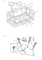
- shows a perspective schematical view of a system according to the invention;
- Fig. 2
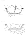
- shows a directly suspended rigid body;
- Fig. 3
- shows a rigid body being suspended via a platform supporting the rigid body;
- Fig. 4
- shows a platform with sensors attached to it;
- Fig. 5
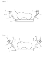
- shows a modification of the system according to
Fig. 4 , wherein the sensors are attached to the carrier; and - Fig. 6
- shows a further modification of the system according to
Fig. 4 , wherein the sensors form part of the elastic elements used for suspending the rigid body; -
Figure 1 shows in conjunction withFigures 2 to 6 asystem 1 that is designed and provided for determining (estimating) the rigid body properties (inertia properties) of a mechanical structure (rigid body 2), which are defined by
where m is the mass, ζG is the location of the center of gravity, and θ is the inertia tensor about the center of gravity
- These ten parameters define a complete model of the structure's (rigid body's) rigid dynamic behavior.
- In order to determine the inertia properties of the
rigid body 2 the latter is suspended in elastic elements p in the form of wires, either directly (cf.Fig. 2 ) or via arectangular platform 30 that serves as a support for the rigid body 2 (cf.Fig. 3 ). The number and arrangement of the suspension wires p can be freely chosen. Preferably, the wire stiffness kp should be low in order to ensure that the structure (rigid body) 2 has six rigid body mode shapes X j (i.e., there are no elastic deformations of the test object (rigid body)); moreover, the wire stiffness kp is preferably chosen to be constant (the force-displacement-relationship is linear) and damping should be light. The combination of soft metal coil springs with more or less rigid wires is one way to meet these requirements. - According to
Figure 1 , therigid body 2 is suspended from acarrier 10 in the form of a hexahedral framework having an upperrectangular frame 11 connected to a lowerrectangular frame 12 via four vertically extending legs 112 (related to a state of the carrier in which the latter is positioned as intended), wherein eachleg 112 connects a corner of thelower frame 12 to an associated opposing corner of theupper frame 11. - For suspending the
rigid body 2, aplatform 30 for supporting therigid body 2 is provided, wherein saidplaform 30 is suspended from thecarrier 10 by means of 8 elastic elements p, wherein each of the 8 elastic elements p is fixed with a free end to the upper frame and with an opposing free end to anedge 31 of theplatform 30, such that elastic elements connected to thesame edge 31 run preferably parallel with respect to each other. - After suspending the test object (rigid body) 2, preferably free vibrations of the six rigid body modes j are initiated in a random fashion, for example by pushing the
structure 2 in an arbitrary direction. The motion (movement) of therigid body 2 in the course of the resulting free vibration is measured about each of the six rigid body degrees of freedom (DOF)(or about a smaller number of degrees of freedom) by means ofsensors 100 and ameasuring device 110 connected thereto. InFigure 1 all sixsensors 100 are indicated as a square at one elastic element of the upper frame 11 (note that there are eight wires (elastic elements) p inFigure 1 but only six sensors 100). - Possible sensor arrangements are depicted in
Figures 4 to 6 . The measuringdevice 110 hands the measured movement (output signals) over to an analyzing means 20 that determines the desired inertia properties r s (cf. Equation (1)). Both the measuringdevice 110 and the analysing means 20 can be formed by acomputer 130 on which a suitable software for measuring said movement and determing said rigid body properties r s is carried out. - In addition to the motion (free vibrations) of the
rigid body 2, in particular only the following parametes need to be known in order to determine the rigid body properties r s: - the number of suspension wires Np,
- the wire stiffness value kp,
- the lengths lp of the unloaded wires,
- the attachment locations ζa,p on the structure (rigid body) 2,
- the attachment locations

- the orientation ñ g of the field of gravity,
- the rigid body properties rp of the platform (if used).
- Note that none of these parameters changes over the lifetime of a
system 1 of the type shown inFig 1 . - Assuming now small displacements and negligible damping effects, the motion of a suspended
rigid body 2 is defined by
wherein δx is a reference point displacement (3x1 vector), δθ is a rotation about the coordinate axes (3x1 vector), f is a translational force (3x1 vector), t is a moment of force (3x1 vector), M is the mass matrix (6x6 matrix),and K is the stiffness matrix (6x6 matrix). - Note that in case of large displacement amplitudes one may use instead of Equation (3) the complete non-linear equations of rigid body motion. In this case one may numerically integrate these Equations in order to derive a method equivalent to the harmonic approach presented below.
- Both the mass matrix M and the suspension stiffness matrix K are functions of the unknown rigid body properties r s. The mass matrix M of the
rigid body 2 is now defined as
wherein the notation [ ]x used in Equation (4) transforms a cross product into a matrix vector multiplication axb= [a] x b, where
- In case a
platform 30 is used, the overall mass matrix M is composed of the unknown rigid body properties of thetest object 2, r s, and the known rigid body properties of the platform r p
- The stiffness matrix K depends on the unknown overall mass and center of gravity,


- The stiffness matrix K also depends on the static equilibrium position defined by the location x õ and orientation θ of the space-fixed coordinate system spanned by

Fig. 2 ). The parameters x õ and θ are used to transform the space-fixed coordinates into body-fixed coordinates as follows,

where R(θ) is a rotational transformation matrix.
- The static equilibrium position (x õ,θ) is not measured, but instead is obtained by minimizing the potential energy function

- In Equation (12), Ve,p represents the elastic energy stored in a given elastic element (wire) p,

where
- The term Vg in Equation (12) represents the gravitational energy of the
rigid body 2 and is defined by the projection of the gravity force, mgn g, onto the vector x õ-ζ G that points from the center of gravity to the space-fixed origin Õ.
- Once the static equilibrium position has been determined by minimizing Equation (12), the stiffness matrix K is obtained as follows

where

- The stiffness matrix K defined by Equation (16) is special in that it accounts for all geometric stiffness effects caused by the gravity preload.
- A softly suspended
rigid body 2 always performs free vibrations with six different mode shapes X j and six natural frequencies ωj. The mode shapes X j and natural frequencies ωj can be obtained by solving the following eigenvalue problem. (Note that moderate viscous damping does not affect the mode shapes and has only marginal effects on the natural frequencies. Therefore, damping does not need to be taken into account at this stage.)
- The mode shapes X j should be normalized in a consistent way, e.g. in such a way that

- In the next step, the mode shapes Xj obtained from Equation (19) are transformed into the corresponding output s1 obtained by a given
sensor 100. In the following this transformation is stated for three different types ofsensors 100 according toFigs. 4 to 6 . Note that in each case at least N1=6 senors must be used, when the rigid body performs vibrations along the six degrees of freedom (preferably, there must be as many sensors as degrees of freedom). According toFigure 4 ,sensors 100 in the form of accelerometers are provided at different points on theplatform 30 or therigid body 2 itself. In case the orientation of theaccelerometer 100 is defined by a unit vector n 1 and its position in body-fixed coordinates is given by ζ 1 (cf.Figs. 2 and3 ), the relationship between the measurement acceleration s1 (1) and the rigid-body mode motion (movement) (δx, δθ) is

-
Accelerometers 100 have the disadvantage that the stiffness and intertia effects of theircable connections 50 to the measurement (measuring) device 110 (computer 130) can distort the measurements. - A second possibility according to
Fig. 5 is the use offorce sensors 100 placed between at least six of the elastic wires p and thecarrier 10. For asensor 100 pointing in a direction ñ 1 (in space-fixed coordinates), the relationship between the rigid body motion (δx, δθ) and the sensor output s1 (2) is defined by

- The matrices R(θ), J 1 (0) and T 1 were already obtained as part of computing the stiffness matrix K.
- The use of space-fixed
force sensors 100 according toFig. 5 eliminates the need for cable connections to moving parts in the system. - A third possibility according to
Figure 6 is to integrate a number offorce sensors 100 into the upper part of the elastic elements (suspension wires) p. In this case, the following relationship defines the sensor output S1 (3) depending on the rigid body movement (δx, δθ):

- Compared with sensors in the form of accelerometers, the motion amplitudes of this type of
force sensor 100 is small, minimizing distortions caused bycables 50. Unlike both accelerometers 100 (Fig. 4 ) and space-fixed force sensors 100 (Fig. 5 ),force sensors 100 that are part of the elastic elements (suspension wires) p are always loaded in the same direction; as a result, errors due to cross-sensitivity can be avoided. - The free vibration signal measured by a given
sensor 100 is defined by
where ζ j is the damping ratio of the j-th rigid body mode. The factors a2j-1 and a2j define the amplitude and the phase of a given mode and are the only parameters that depend on the random initial excitation. - Equation (26) defines the theoretical vibration signals of the
rigid body 2. This expression can be fitted to the measured time-domain signals,(tk), in order to identify the rigid body proporties r s. The resulting optimization problem is defined by

- Note that the modal damping ratios ζj and the scaling factors a2j-1 and a2j must be identified at the same time as the rigid body properties, even though these parameters may not be of interest to the experimenter.
- Conventional nonlinear least-squares routines (e.g. the Gauss-Newton-Algorithms or the Leuvenberg-Marquardt Algorithms) can be used to solve the optimization problem Equation (27).
- Preferably, all calculations in the course of the method according to the ivention outlined above are performed by the analysing
means 20, i.e., in particular by saidcomputer 130 and said software carried out by saidcomputer 130.
Claims (13)
- System for determining inertia properties of a rigid body, particularly the inertia tensor, the mass and/or the position of the center of mass, comprising:- a carrier (10), which is designed for suspending a rigid body (S) from the carrier (10), such that the rigid body (2) is able to perform movements along a number of degrees of freedom of the rigid body (2),- as many sensors (100) as degrees of freedom of the rigid body (2) providing output signals for detecting the movement of the rigid body (2) along said number of degrees of freedom of the rigid body (2),- a measuring device (110) cooperating with the sensors (100), wherein the measuring device (110) is configured to measure said movement of the rigid body (2) by means of said output signals ((tk)), and
 - an analysing means (20) configured for determining from said output signals ((tk)) said intertia properties (r s) of the rigid body (2).
- System according to claim 1, characterized in that said movement corresponds to free vibrations along the number of degrees of freedom of the rigid body (2).
- System according to claim 1 or 2, characterized in that the measuring device (110) is configured to measure output signals ((tk)) corresponding to the translation of the rigid body (2) along the three orthogonal axes and the rotations about these axes as a function of time (tk).

- System according to one of the preceding claims, characterized in that the analysing means (20) is configured to fit said measured output signal ((tk)) to the function


- System according to claim 4, characterized in that the analysing means (20) is configured to determine said inertia properties (r s) by minimizing the expression

with respect to
- System according to one of the preceding claims, characterized in that the system comprises elastic elements (p), which are designed for suspending the rigid body (2) from the carrier (10), wherein the rigid body (2) is suspended from the carrier (10) via said elastic elements (p), wherein in particular the elastic elements (p) are designed as wires and/or springs, wherein particularly one, two three, four, five, six, seven or eight elastic elements (p) are provided.
- System according to claim 6, characterized in that the system comprises a platform (30) that is designed for suspending the rigid body (2), wherein the platform (30) is suspended from the carrier (10) via said elastic elements (p) in order to suspend the rigid body (S) from the carrier (10).
- System according to one of the preceding claims, characterized in that said sensors (100) are arranged on said platform (30), on the carrier (10), or form a part of an associated elastic element (p).
- System according to one of the preceding claims, characterized in that said carrier (10) is designed as a hexahedral framework.
- Method for determining intertia properties of a rigid body, particularly the inertia tensor, the mass and/or the position of the center of mass, wherein in particular the system according to one of the preceding claims is used for conducting the method, the method comprising the steps of:- suspending the rigid body (2) from a carrier (10),- forcing the rigid body (2) to perform movements along a number of degrees of freedom of the rigid body (2),- measuring an output signal ((tk)) corresponding to said movement of the rigid body (2) automatically, and
 - determining said inertia properties (r s) from the said movement ((tk)) automatically,
 - wherein particularly the rigid body (2) is forced to perform movements in the form of free vibrations, wherein particularly said output ((tk)) corresponds to the translation of the rigid body (2) along three orthogonal axes and the rotation of the rigid body (2) about these axes as a function of time (tk), respectively.
- Method according to claim 10, characterized in that said measured output signal ((tk)) is automatically fitted to the function


- Method according to claim 11,characterized in that said inertia properties are automatically determined by minimizing the expression
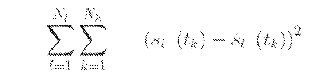
with respect to
- Method according to one of the claims 10 to 12, characterized in that besides said measured output signals ((tk)), merely the following parameters are used to determine said inertia properties of said rigid body:
 - the number (Np) of the elastic elements (p),- the stiffness value of the elastic elements (kp),- the lengths (lp) of the unloaded elastic elements (p),- the attachment locations (ζ a,p) of the elastic elements (p) on the carrier (10), particularly in space-fixed coordinates,- the attachment locations (
 - the orientation of the field of gravity (ñg), and- particularly the inertia properties (rp) of the platform.
Priority Applications (4)
| Application Number | Priority Date | Filing Date | Title |
|---|---|---|---|
| EP11168278.7A EP2508861B1 (en) | 2011-04-04 | 2011-05-31 | System and method for determining inertia properties of a rigid body |
| PCT/EP2012/059219 WO2012163688A1 (en) | 2011-05-31 | 2012-05-17 | System and method for determining inertia properties of a rigid body |
| US14/122,248 US10197468B2 (en) | 2011-05-31 | 2012-05-17 | System and method for determining inertia properties of a rigid body |
| JP2014513108A JP5878977B2 (en) | 2011-05-31 | 2012-05-17 | System and method for determining inertial properties of rigid bodies |
Applications Claiming Priority (2)
| Application Number | Priority Date | Filing Date | Title |
|---|---|---|---|
| EP11161079 | 2011-04-04 | ||
| EP11168278.7A EP2508861B1 (en) | 2011-04-04 | 2011-05-31 | System and method for determining inertia properties of a rigid body |
Publications (2)
| Publication Number | Publication Date |
|---|---|
| EP2508861A1 true EP2508861A1 (en) | 2012-10-10 |
| EP2508861B1 EP2508861B1 (en) | 2018-11-07 |
Family
ID=46275790
Family Applications (1)
| Application Number | Title | Priority Date | Filing Date |
|---|---|---|---|
| EP11168278.7A Active EP2508861B1 (en) | 2011-04-04 | 2011-05-31 | System and method for determining inertia properties of a rigid body |
Country Status (4)
| Country | Link |
|---|---|
| US (1) | US10197468B2 (en) |
| EP (1) | EP2508861B1 (en) |
| JP (1) | JP5878977B2 (en) |
| WO (1) | WO2012163688A1 (en) |
Cited By (4)
| Publication number | Priority date | Publication date | Assignee | Title |
|---|---|---|---|---|
| CN105203259A (en) * | 2015-09-25 | 2015-12-30 | 哈尔滨工业大学 | Aircraft simulation air bearing table inertia regulating and measuring device and method |
| CN107870063A (en) * | 2017-09-21 | 2018-04-03 | 深圳航天东方红海特卫星有限公司 | Spacecraft rotary inertia inflight measurement method based on the conservation of momentum |
| CN110750837A (en) * | 2019-10-24 | 2020-02-04 | 中国航空工业集团公司沈阳飞机设计研究所 | A method for evaluating the residual control capability of an aircraft |
| EP4043777A1 (en) | 2021-02-16 | 2022-08-17 | Resonic GmbH | Module for positioning and orienting an object, system comprising said module, use, and method |
Families Citing this family (9)
| Publication number | Priority date | Publication date | Assignee | Title |
|---|---|---|---|---|
| DE102013208875A1 (en) * | 2013-05-14 | 2014-12-04 | Resonic Gmbh | Apparatus and method for determining inertial properties of an object |
| CN105784276B (en) * | 2016-05-11 | 2017-12-26 | 大连理工大学 | Device for automatic measurement and adjustment of multi-axial inertia of test model of offshore structure and its application method |
| CN107044913A (en) * | 2017-06-15 | 2017-08-15 | 重庆大学 | A kind of engine inertia parameter identification device and method |
| CN113280975B (en) * | 2021-05-24 | 2022-08-09 | 桂林电子科技大学 | Large-scale component quality measurement method based on frequency response function quality line |
| CN113483706B (en) * | 2021-06-23 | 2022-03-18 | 东风汽车股份有限公司 | Inertial parameter measuring method for countless-mode power assembly |
| US12281955B2 (en) | 2022-07-08 | 2025-04-22 | Owlfly Llc | Method for measuring mass distribution within objects using moment-of-inertia |
| CN115931222A (en) * | 2022-12-16 | 2023-04-07 | 中国科学院长春光学精密机械与物理研究所 | A centroid measuring device and measuring method |
| CN120654456B (en) * | 2025-04-30 | 2026-04-21 | 华能澜沧江水电股份有限公司 | Calculation method of broadband consistent damping force in time domain dynamic analysis |
| CN120609500B (en) * | 2025-06-17 | 2026-04-21 | 中山大学 | A method for measuring the center of mass based on the multipole expansion of gravitational potential energy |
Citations (1)
| Publication number | Priority date | Publication date | Assignee | Title |
|---|---|---|---|---|
| US20060010965A1 (en) * | 2002-05-31 | 2006-01-19 | Gianpiero Mastinu | Device for measuring the inertia tensor of a rigid body |
Family Cites Families (24)
| Publication number | Priority date | Publication date | Assignee | Title |
|---|---|---|---|---|
| JPS54157684A (en) | 1978-06-01 | 1979-12-12 | Mitsubishi Heavy Ind Ltd | Measuring method for position of center of gravity |
| FR2619213B1 (en) * | 1987-08-05 | 1990-07-06 | Aerospatiale | APPARATUS FOR MEASURING THE MASS CHARACTERISTICS OF A BODY AND ITS APPLICATION TO MEASURING THE CHARACTERISTICS OF A DRY SATELLITE. |
| JPH0282128A (en) * | 1988-09-19 | 1990-03-22 | Fujitsu Ltd | Measuring method for moment of inertia |
| JP3064733B2 (en) * | 1993-03-30 | 2000-07-12 | 寛 松久 | Dynamic vibration absorber of pendulum type structure |
| US5309753A (en) * | 1993-04-08 | 1994-05-10 | U.S. Golf Association | Apparatus and method for determining the inertia matrix of a rigid body |
| JP3142444B2 (en) * | 1994-08-22 | 2001-03-07 | トヨタ自動車株式会社 | Moment of inertia measurement device |
| USRE39906E1 (en) * | 1995-10-26 | 2007-11-06 | Immersion Corporation | Gyro-stabilized platforms for force-feedback applications |
| US5931441A (en) * | 1996-02-29 | 1999-08-03 | Nikon Corporation | Method of isolating vibration in exposure apparatus |
| JPH1089403A (en) * | 1996-09-10 | 1998-04-07 | Nikon Corp | Vibration control device |
| JP3187368B2 (en) | 1998-05-08 | 2001-07-11 | 株式会社住友シチックス尼崎 | Ladle weighing device and its weighing method |
| US6338274B1 (en) * | 1999-05-21 | 2002-01-15 | Milli Sensor Systems & Actuators, Inc. | Tuned flexure accelerometer |
| US6629460B2 (en) * | 2001-08-10 | 2003-10-07 | The Boeing Company | Isolated resonator gyroscope |
| US6881963B2 (en) * | 2002-11-08 | 2005-04-19 | Canon Kabushiki Kaisha | Vibration control of an object |
| US7630869B2 (en) * | 2003-05-27 | 2009-12-08 | University Of Washington | Method for predicting vibrational characteristics of rotating structures |
| US7406867B2 (en) * | 2005-06-27 | 2008-08-05 | Milli Sensor Systems + Actuators | G2-Gyroscope: MEMS gyroscope with output oscillation about the normal to the plane |
| US8396320B2 (en) * | 2007-01-19 | 2013-03-12 | Purdue Research Foundation | Method and apparatus for determining the stray-light point-spread function of an imaging system |
| DE102007017462B4 (en) * | 2007-04-10 | 2012-08-30 | Aker Mtw Werft Gmbh | Method for determining focal points in large structures |
| DE102008024513B4 (en) * | 2008-05-21 | 2017-08-24 | Liebherr-Werk Nenzing Gmbh | Crane control with active coast sequence |
| US20100030532A1 (en) * | 2008-06-12 | 2010-02-04 | Jasbir Arora | System and methods for digital human model prediction and simulation |
| DE102009002392A1 (en) * | 2009-04-15 | 2010-11-04 | Airbus Deutschland Gmbh | System and method for determining local accelerations, dynamic load distributions and aerodynamic data in an aircraft |
| JP2011089958A (en) | 2009-10-26 | 2011-05-06 | Tokyu Car Corp | Method for measuring height of center of gravity |
| DE102010028311A1 (en) * | 2010-04-28 | 2011-11-03 | Airbus Operations Gmbh | System and method for minimizing buffeting |
| JP5532238B2 (en) * | 2010-07-08 | 2014-06-25 | 国立大学法人東京工業大学 | Rigid body characteristic identification device and rigid body characteristic identification method |
| WO2012131682A1 (en) * | 2011-03-31 | 2012-10-04 | Ramot At Tel-Aviv University Ltd. | Compliant structures with time-varying moment of inertia |
-
2011
- 2011-05-31 EP EP11168278.7A patent/EP2508861B1/en active Active
-
2012
- 2012-05-17 JP JP2014513108A patent/JP5878977B2/en not_active Expired - Fee Related
- 2012-05-17 WO PCT/EP2012/059219 patent/WO2012163688A1/en not_active Ceased
- 2012-05-17 US US14/122,248 patent/US10197468B2/en active Active
Patent Citations (1)
| Publication number | Priority date | Publication date | Assignee | Title |
|---|---|---|---|---|
| US20060010965A1 (en) * | 2002-05-31 | 2006-01-19 | Gianpiero Mastinu | Device for measuring the inertia tensor of a rigid body |
Cited By (6)
| Publication number | Priority date | Publication date | Assignee | Title |
|---|---|---|---|---|
| CN105203259A (en) * | 2015-09-25 | 2015-12-30 | 哈尔滨工业大学 | Aircraft simulation air bearing table inertia regulating and measuring device and method |
| CN107870063A (en) * | 2017-09-21 | 2018-04-03 | 深圳航天东方红海特卫星有限公司 | Spacecraft rotary inertia inflight measurement method based on the conservation of momentum |
| CN107870063B (en) * | 2017-09-21 | 2020-01-03 | 深圳航天东方红海特卫星有限公司 | Spacecraft rotational inertia on-orbit measurement method based on momentum conservation |
| CN110750837A (en) * | 2019-10-24 | 2020-02-04 | 中国航空工业集团公司沈阳飞机设计研究所 | A method for evaluating the residual control capability of an aircraft |
| EP4043777A1 (en) | 2021-02-16 | 2022-08-17 | Resonic GmbH | Module for positioning and orienting an object, system comprising said module, use, and method |
| WO2022175272A1 (en) | 2021-02-16 | 2022-08-25 | Resonic Gmbh | Module for positioning and orienting an object, system comprising said module, use, and method |
Also Published As
| Publication number | Publication date |
|---|---|
| EP2508861B1 (en) | 2018-11-07 |
| WO2012163688A1 (en) | 2012-12-06 |
| JP5878977B2 (en) | 2016-03-08 |
| US20140088914A1 (en) | 2014-03-27 |
| JP2014515492A (en) | 2014-06-30 |
| US10197468B2 (en) | 2019-02-05 |
Similar Documents
| Publication | Publication Date | Title |
|---|---|---|
| EP2508861B1 (en) | System and method for determining inertia properties of a rigid body | |
| Moon et al. | Fatigue life evaluation of mechanical components using vibration fatigue analysis technique | |
| Døssing | Structural testing | |
| US9188503B2 (en) | Rigid body characteristic identification system and rigid body characteristic identification method | |
| Vollebregt | User guide for CONTACT, Rolling and sliding contact with friction | |
| Almeida et al. | Identification of rigid body properties from vibration measurements | |
| Zhou et al. | Modelling and testing of a soft suspension design for a reaction/momentum wheel assembly | |
| EP2390644B1 (en) | Method and system for determining static and/or dynamic, loads using inverse dynamic calibration | |
| KR101601094B1 (en) | Measuring System of Inertia and Mass Center | |
| Law et al. | Structural damage detection from coupling forces between substructures under support excitation | |
| JP5203851B2 (en) | Rigidity evaluation support device, rigidity evaluation support method and program | |
| Previati et al. | Measurement of the mass properties of rigid bodies by means of multi-filar pendulums–influence of test rig flexibility | |
| Lagerblad et al. | A methodology for strain-based fatigue damage prediction by combining finite element modelling with vibration measurements | |
| Mayes et al. | Extending the frequency band for fixed base modal analysis on a vibration slip table | |
| CN102270249B (en) | Method for identifying characteristic frequency of parts | |
| Winkel et al. | Modal survey of the MPCV Orion European Service Module Structural Test Article using a multi-axis shake table | |
| Van Fossen et al. | An acceleration-based approach to force limiting a random vibration test | |
| CN113280975B (en) | Large-scale component quality measurement method based on frequency response function quality line | |
| Ashory et al. | On the accuracy of estimation of rigid body inertia properties from modal testing results | |
| Barbin et al. | Three-axis MEMS accelerometer for structural inspection | |
| Zembaty et al. | Application of rotation rate sensors in measuring beam flexure and structural health monitoring | |
| Wyen et al. | Experimental modal analysis of an aircraft fuselage panel | |
| Hung et al. | Identification of dynamic systems from data composed by combination of their response compoments | |
| Füllekrug et al. | Inertia Parameter Identification from Base Excitation Test Dat | |
| Vári et al. | Strain modal testing-a critical appraisal |
Legal Events
| Date | Code | Title | Description |
|---|---|---|---|
| PUAI | Public reference made under article 153(3) epc to a published international application that has entered the european phase |
Free format text: ORIGINAL CODE: 0009012 |
|
| AK | Designated contracting states |
Kind code of ref document: A1 Designated state(s): AL AT BE BG CH CY CZ DE DK EE ES FI FR GB GR HR HU IE IS IT LI LT LU LV MC MK MT NL NO PL PT RO RS SE SI SK SM TR |
|
| AX | Request for extension of the european patent |
Extension state: BA ME |
|
| 17P | Request for examination filed |
Effective date: 20130410 |
|
| 17Q | First examination report despatched |
Effective date: 20160412 |
|
| STAA | Information on the status of an ep patent application or granted ep patent |
Free format text: STATUS: EXAMINATION IS IN PROGRESS |
|
| REG | Reference to a national code |
Ref country code: DE Ref legal event code: R079 Ref document number: 602011053571 Country of ref document: DE Free format text: PREVIOUS MAIN CLASS: G01M0001100000 Ipc: G06F0017110000 |
|
| RIC1 | Information provided on ipc code assigned before grant |
Ipc: G06F 17/11 20060101AFI20170412BHEP Ipc: G01M 1/10 20060101ALI20170412BHEP |
|
| GRAP | Despatch of communication of intention to grant a patent |
Free format text: ORIGINAL CODE: EPIDOSNIGR1 |
|
| STAA | Information on the status of an ep patent application or granted ep patent |
Free format text: STATUS: GRANT OF PATENT IS INTENDED |
|
| INTG | Intention to grant announced |
Effective date: 20170524 |
|
| GRAJ | Information related to disapproval of communication of intention to grant by the applicant or resumption of examination proceedings by the epo deleted |
Free format text: ORIGINAL CODE: EPIDOSDIGR1 |
|
| STAA | Information on the status of an ep patent application or granted ep patent |
Free format text: STATUS: EXAMINATION IS IN PROGRESS |
|
| GRAP | Despatch of communication of intention to grant a patent |
Free format text: ORIGINAL CODE: EPIDOSNIGR1 |
|
| INTC | Intention to grant announced (deleted) | ||
| STAA | Information on the status of an ep patent application or granted ep patent |
Free format text: STATUS: GRANT OF PATENT IS INTENDED |
|
| INTG | Intention to grant announced |
Effective date: 20171109 |
|
| GRAJ | Information related to disapproval of communication of intention to grant by the applicant or resumption of examination proceedings by the epo deleted |
Free format text: ORIGINAL CODE: EPIDOSDIGR1 |
|
| STAA | Information on the status of an ep patent application or granted ep patent |
Free format text: STATUS: EXAMINATION IS IN PROGRESS |
|
| GRAP | Despatch of communication of intention to grant a patent |
Free format text: ORIGINAL CODE: EPIDOSNIGR1 |
|
| STAA | Information on the status of an ep patent application or granted ep patent |
Free format text: STATUS: GRANT OF PATENT IS INTENDED |
|
| INTC | Intention to grant announced (deleted) | ||
| INTG | Intention to grant announced |
Effective date: 20180509 |
|
| GRAS | Grant fee paid |
Free format text: ORIGINAL CODE: EPIDOSNIGR3 |
|
| GRAA | (expected) grant |
Free format text: ORIGINAL CODE: 0009210 |
|
| STAA | Information on the status of an ep patent application or granted ep patent |
Free format text: STATUS: THE PATENT HAS BEEN GRANTED |
|
| AK | Designated contracting states |
Kind code of ref document: B1 Designated state(s): AL AT BE BG CH CY CZ DE DK EE ES FI FR GB GR HR HU IE IS IT LI LT LU LV MC MK MT NL NO PL PT RO RS SE SI SK SM TR |
|
| REG | Reference to a national code |
Ref country code: GB Ref legal event code: FG4D |
|
| REG | Reference to a national code |
Ref country code: CH Ref legal event code: EP Ref country code: AT Ref legal event code: REF Ref document number: 1062920 Country of ref document: AT Kind code of ref document: T Effective date: 20181115 |
|
| REG | Reference to a national code |
Ref country code: IE Ref legal event code: FG4D |
|
| REG | Reference to a national code |
Ref country code: DE Ref legal event code: R096 Ref document number: 602011053571 Country of ref document: DE |
|
| REG | Reference to a national code |
Ref country code: NL Ref legal event code: MP Effective date: 20181107 |
|
| REG | Reference to a national code |
Ref country code: LT Ref legal event code: MG4D |
|
| REG | Reference to a national code |
Ref country code: AT Ref legal event code: MK05 Ref document number: 1062920 Country of ref document: AT Kind code of ref document: T Effective date: 20181107 |
|
| PG25 | Lapsed in a contracting state [announced via postgrant information from national office to epo] |
Ref country code: ES Free format text: LAPSE BECAUSE OF FAILURE TO SUBMIT A TRANSLATION OF THE DESCRIPTION OR TO PAY THE FEE WITHIN THE PRESCRIBED TIME-LIMIT Effective date: 20181107 Ref country code: LV Free format text: LAPSE BECAUSE OF FAILURE TO SUBMIT A TRANSLATION OF THE DESCRIPTION OR TO PAY THE FEE WITHIN THE PRESCRIBED TIME-LIMIT Effective date: 20181107 Ref country code: AT Free format text: LAPSE BECAUSE OF FAILURE TO SUBMIT A TRANSLATION OF THE DESCRIPTION OR TO PAY THE FEE WITHIN THE PRESCRIBED TIME-LIMIT Effective date: 20181107 Ref country code: HR Free format text: LAPSE BECAUSE OF FAILURE TO SUBMIT A TRANSLATION OF THE DESCRIPTION OR TO PAY THE FEE WITHIN THE PRESCRIBED TIME-LIMIT Effective date: 20181107 Ref country code: IS Free format text: LAPSE BECAUSE OF FAILURE TO SUBMIT A TRANSLATION OF THE DESCRIPTION OR TO PAY THE FEE WITHIN THE PRESCRIBED TIME-LIMIT Effective date: 20190307 Ref country code: FI Free format text: LAPSE BECAUSE OF FAILURE TO SUBMIT A TRANSLATION OF THE DESCRIPTION OR TO PAY THE FEE WITHIN THE PRESCRIBED TIME-LIMIT Effective date: 20181107 Ref country code: BG Free format text: LAPSE BECAUSE OF FAILURE TO SUBMIT A TRANSLATION OF THE DESCRIPTION OR TO PAY THE FEE WITHIN THE PRESCRIBED TIME-LIMIT Effective date: 20190207 Ref country code: LT Free format text: LAPSE BECAUSE OF FAILURE TO SUBMIT A TRANSLATION OF THE DESCRIPTION OR TO PAY THE FEE WITHIN THE PRESCRIBED TIME-LIMIT Effective date: 20181107 Ref country code: NO Free format text: LAPSE BECAUSE OF FAILURE TO SUBMIT A TRANSLATION OF THE DESCRIPTION OR TO PAY THE FEE WITHIN THE PRESCRIBED TIME-LIMIT Effective date: 20190207 |
|
| PG25 | Lapsed in a contracting state [announced via postgrant information from national office to epo] |
Ref country code: RS Free format text: LAPSE BECAUSE OF FAILURE TO SUBMIT A TRANSLATION OF THE DESCRIPTION OR TO PAY THE FEE WITHIN THE PRESCRIBED TIME-LIMIT Effective date: 20181107 Ref country code: GR Free format text: LAPSE BECAUSE OF FAILURE TO SUBMIT A TRANSLATION OF THE DESCRIPTION OR TO PAY THE FEE WITHIN THE PRESCRIBED TIME-LIMIT Effective date: 20190208 Ref country code: NL Free format text: LAPSE BECAUSE OF FAILURE TO SUBMIT A TRANSLATION OF THE DESCRIPTION OR TO PAY THE FEE WITHIN THE PRESCRIBED TIME-LIMIT Effective date: 20181107 Ref country code: PT Free format text: LAPSE BECAUSE OF FAILURE TO SUBMIT A TRANSLATION OF THE DESCRIPTION OR TO PAY THE FEE WITHIN THE PRESCRIBED TIME-LIMIT Effective date: 20190307 Ref country code: SE Free format text: LAPSE BECAUSE OF FAILURE TO SUBMIT A TRANSLATION OF THE DESCRIPTION OR TO PAY THE FEE WITHIN THE PRESCRIBED TIME-LIMIT Effective date: 20181107 Ref country code: AL Free format text: LAPSE BECAUSE OF FAILURE TO SUBMIT A TRANSLATION OF THE DESCRIPTION OR TO PAY THE FEE WITHIN THE PRESCRIBED TIME-LIMIT Effective date: 20181107 |
|
| PG25 | Lapsed in a contracting state [announced via postgrant information from national office to epo] |
Ref country code: DK Free format text: LAPSE BECAUSE OF FAILURE TO SUBMIT A TRANSLATION OF THE DESCRIPTION OR TO PAY THE FEE WITHIN THE PRESCRIBED TIME-LIMIT Effective date: 20181107 Ref country code: PL Free format text: LAPSE BECAUSE OF FAILURE TO SUBMIT A TRANSLATION OF THE DESCRIPTION OR TO PAY THE FEE WITHIN THE PRESCRIBED TIME-LIMIT Effective date: 20181107 Ref country code: CZ Free format text: LAPSE BECAUSE OF FAILURE TO SUBMIT A TRANSLATION OF THE DESCRIPTION OR TO PAY THE FEE WITHIN THE PRESCRIBED TIME-LIMIT Effective date: 20181107 Ref country code: IT Free format text: LAPSE BECAUSE OF FAILURE TO SUBMIT A TRANSLATION OF THE DESCRIPTION OR TO PAY THE FEE WITHIN THE PRESCRIBED TIME-LIMIT Effective date: 20181107 |
|
| REG | Reference to a national code |
Ref country code: DE Ref legal event code: R097 Ref document number: 602011053571 Country of ref document: DE |
|
| PG25 | Lapsed in a contracting state [announced via postgrant information from national office to epo] |
Ref country code: RO Free format text: LAPSE BECAUSE OF FAILURE TO SUBMIT A TRANSLATION OF THE DESCRIPTION OR TO PAY THE FEE WITHIN THE PRESCRIBED TIME-LIMIT Effective date: 20181107 Ref country code: SK Free format text: LAPSE BECAUSE OF FAILURE TO SUBMIT A TRANSLATION OF THE DESCRIPTION OR TO PAY THE FEE WITHIN THE PRESCRIBED TIME-LIMIT Effective date: 20181107 Ref country code: SM Free format text: LAPSE BECAUSE OF FAILURE TO SUBMIT A TRANSLATION OF THE DESCRIPTION OR TO PAY THE FEE WITHIN THE PRESCRIBED TIME-LIMIT Effective date: 20181107 Ref country code: EE Free format text: LAPSE BECAUSE OF FAILURE TO SUBMIT A TRANSLATION OF THE DESCRIPTION OR TO PAY THE FEE WITHIN THE PRESCRIBED TIME-LIMIT Effective date: 20181107 |
|
| PLBE | No opposition filed within time limit |
Free format text: ORIGINAL CODE: 0009261 |
|
| STAA | Information on the status of an ep patent application or granted ep patent |
Free format text: STATUS: NO OPPOSITION FILED WITHIN TIME LIMIT |
|
| 26N | No opposition filed |
Effective date: 20190808 |
|
| PG25 | Lapsed in a contracting state [announced via postgrant information from national office to epo] |
Ref country code: SI Free format text: LAPSE BECAUSE OF FAILURE TO SUBMIT A TRANSLATION OF THE DESCRIPTION OR TO PAY THE FEE WITHIN THE PRESCRIBED TIME-LIMIT Effective date: 20181107 |
|
| REG | Reference to a national code |
Ref country code: CH Ref legal event code: PL |
|
| PG25 | Lapsed in a contracting state [announced via postgrant information from national office to epo] |
Ref country code: CH Free format text: LAPSE BECAUSE OF NON-PAYMENT OF DUE FEES Effective date: 20190531 Ref country code: MC Free format text: LAPSE BECAUSE OF FAILURE TO SUBMIT A TRANSLATION OF THE DESCRIPTION OR TO PAY THE FEE WITHIN THE PRESCRIBED TIME-LIMIT Effective date: 20181107 Ref country code: LI Free format text: LAPSE BECAUSE OF NON-PAYMENT OF DUE FEES Effective date: 20190531 |
|
| REG | Reference to a national code |
Ref country code: BE Ref legal event code: MM Effective date: 20190531 |
|
| PG25 | Lapsed in a contracting state [announced via postgrant information from national office to epo] |
Ref country code: LU Free format text: LAPSE BECAUSE OF NON-PAYMENT OF DUE FEES Effective date: 20190531 |
|
| PG25 | Lapsed in a contracting state [announced via postgrant information from national office to epo] |
Ref country code: TR Free format text: LAPSE BECAUSE OF FAILURE TO SUBMIT A TRANSLATION OF THE DESCRIPTION OR TO PAY THE FEE WITHIN THE PRESCRIBED TIME-LIMIT Effective date: 20181107 |
|
| PG25 | Lapsed in a contracting state [announced via postgrant information from national office to epo] |
Ref country code: IE Free format text: LAPSE BECAUSE OF NON-PAYMENT OF DUE FEES Effective date: 20190531 |
|
| PG25 | Lapsed in a contracting state [announced via postgrant information from national office to epo] |
Ref country code: BE Free format text: LAPSE BECAUSE OF NON-PAYMENT OF DUE FEES Effective date: 20190531 |
|
| PG25 | Lapsed in a contracting state [announced via postgrant information from national office to epo] |
Ref country code: CY Free format text: LAPSE BECAUSE OF FAILURE TO SUBMIT A TRANSLATION OF THE DESCRIPTION OR TO PAY THE FEE WITHIN THE PRESCRIBED TIME-LIMIT Effective date: 20181107 |
|
| PG25 | Lapsed in a contracting state [announced via postgrant information from national office to epo] |
Ref country code: MT Free format text: LAPSE BECAUSE OF FAILURE TO SUBMIT A TRANSLATION OF THE DESCRIPTION OR TO PAY THE FEE WITHIN THE PRESCRIBED TIME-LIMIT Effective date: 20181107 Ref country code: HU Free format text: LAPSE BECAUSE OF FAILURE TO SUBMIT A TRANSLATION OF THE DESCRIPTION OR TO PAY THE FEE WITHIN THE PRESCRIBED TIME-LIMIT; INVALID AB INITIO Effective date: 20110531 |
|
| PG25 | Lapsed in a contracting state [announced via postgrant information from national office to epo] |
Ref country code: MK Free format text: LAPSE BECAUSE OF FAILURE TO SUBMIT A TRANSLATION OF THE DESCRIPTION OR TO PAY THE FEE WITHIN THE PRESCRIBED TIME-LIMIT Effective date: 20181107 |
|
| PGFP | Annual fee paid to national office [announced via postgrant information from national office to epo] |
Ref country code: DE Payment date: 20230519 Year of fee payment: 13 |
|
| REG | Reference to a national code |
Ref country code: DE Ref legal event code: R119 Ref document number: 602011053571 Country of ref document: DE |
|
| PG25 | Lapsed in a contracting state [announced via postgrant information from national office to epo] |
Ref country code: DE Free format text: LAPSE BECAUSE OF NON-PAYMENT OF DUE FEES Effective date: 20241203 |
|
| PGFP | Annual fee paid to national office [announced via postgrant information from national office to epo] |
Ref country code: GB Payment date: 20260327 Year of fee payment: 16 |
|
| PGFP | Annual fee paid to national office [announced via postgrant information from national office to epo] |
Ref country code: FR Payment date: 20260522 Year of fee payment: 16 |