EP2508637A1 - Bearing steel - Google Patents
Bearing steel Download PDFInfo
- Publication number
- EP2508637A1 EP2508637A1 EP10833433A EP10833433A EP2508637A1 EP 2508637 A1 EP2508637 A1 EP 2508637A1 EP 10833433 A EP10833433 A EP 10833433A EP 10833433 A EP10833433 A EP 10833433A EP 2508637 A1 EP2508637 A1 EP 2508637A1
- Authority
- EP
- European Patent Office
- Prior art keywords
- mass
- steel
- less
- rolling contact
- ingot
- Prior art date
- Legal status (The legal status is an assumption and is not a legal conclusion. Google has not performed a legal analysis and makes no representation as to the accuracy of the status listed.)
- Granted
Links
- 229910000831 Steel Inorganic materials 0.000 title claims abstract description 281
- 239000010959 steel Substances 0.000 title claims abstract description 281
- 230000005496 eutectics Effects 0.000 claims abstract description 49
- 239000000203 mixture Substances 0.000 claims abstract description 26
- 230000015572 biosynthetic process Effects 0.000 claims abstract description 22
- 239000012535 impurity Substances 0.000 claims abstract description 6
- 229910052799 carbon Inorganic materials 0.000 claims description 13
- 229910052804 chromium Inorganic materials 0.000 claims description 9
- 229910052748 manganese Inorganic materials 0.000 claims description 8
- 229910052710 silicon Inorganic materials 0.000 claims description 7
- 229910052782 aluminium Inorganic materials 0.000 claims description 6
- 238000005266 casting Methods 0.000 abstract description 20
- 238000005204 segregation Methods 0.000 abstract description 20
- 238000005096 rolling process Methods 0.000 description 68
- 230000000052 comparative effect Effects 0.000 description 38
- 238000012360 testing method Methods 0.000 description 22
- 229910052720 vanadium Inorganic materials 0.000 description 17
- 239000011651 chromium Substances 0.000 description 16
- 238000005242 forging Methods 0.000 description 15
- 238000000034 method Methods 0.000 description 13
- 230000003247 decreasing effect Effects 0.000 description 12
- 229910052758 niobium Inorganic materials 0.000 description 12
- 238000005070 sampling Methods 0.000 description 12
- 229910052721 tungsten Inorganic materials 0.000 description 11
- 229910052726 zirconium Inorganic materials 0.000 description 11
- 230000006866 deterioration Effects 0.000 description 10
- 229910052719 titanium Inorganic materials 0.000 description 10
- 230000000694 effects Effects 0.000 description 9
- 239000000463 material Substances 0.000 description 9
- 229910052802 copper Inorganic materials 0.000 description 8
- 229910052750 molybdenum Inorganic materials 0.000 description 8
- 238000010791 quenching Methods 0.000 description 8
- 238000011156 evaluation Methods 0.000 description 7
- 238000004519 manufacturing process Methods 0.000 description 7
- 229910052759 nickel Inorganic materials 0.000 description 7
- 229910000760 Hardened steel Inorganic materials 0.000 description 5
- 238000005520 cutting process Methods 0.000 description 5
- 230000008569 process Effects 0.000 description 5
- 238000005496 tempering Methods 0.000 description 5
- QVGXLLKOCUKJST-UHFFFAOYSA-N atomic oxygen Chemical compound [O] QVGXLLKOCUKJST-UHFFFAOYSA-N 0.000 description 4
- 229910001566 austenite Inorganic materials 0.000 description 4
- 238000009749 continuous casting Methods 0.000 description 4
- 150000004767 nitrides Chemical class 0.000 description 4
- 229910052760 oxygen Inorganic materials 0.000 description 4
- 239000001301 oxygen Substances 0.000 description 4
- 238000002791 soaking Methods 0.000 description 4
- 229910001220 stainless steel Inorganic materials 0.000 description 4
- OKTJSMMVPCPJKN-UHFFFAOYSA-N Carbon Chemical compound [C] OKTJSMMVPCPJKN-UHFFFAOYSA-N 0.000 description 3
- 238000005256 carbonitriding Methods 0.000 description 3
- 230000008018 melting Effects 0.000 description 3
- 238000002844 melting Methods 0.000 description 3
- 238000012986 modification Methods 0.000 description 3
- 230000004048 modification Effects 0.000 description 3
- 230000000171 quenching effect Effects 0.000 description 3
- 238000004904 shortening Methods 0.000 description 3
- 239000003795 chemical substances by application Substances 0.000 description 2
- 230000001186 cumulative effect Effects 0.000 description 2
- 238000007872 degassing Methods 0.000 description 2
- 238000009792 diffusion process Methods 0.000 description 2
- 238000009661 fatigue test Methods 0.000 description 2
- 238000011068 loading method Methods 0.000 description 2
- 230000007774 longterm Effects 0.000 description 2
- 230000009467 reduction Effects 0.000 description 2
- 238000007670 refining Methods 0.000 description 2
- 238000009628 steelmaking Methods 0.000 description 2
- 239000000126 substance Substances 0.000 description 2
- 238000010998 test method Methods 0.000 description 2
- 229910001339 C alloy Inorganic materials 0.000 description 1
- 238000003723 Smelting Methods 0.000 description 1
- NINIDFKCEFEMDL-UHFFFAOYSA-N Sulfur Chemical compound [S] NINIDFKCEFEMDL-UHFFFAOYSA-N 0.000 description 1
- 230000004913 activation Effects 0.000 description 1
- 229910052787 antimony Inorganic materials 0.000 description 1
- 229910052785 arsenic Inorganic materials 0.000 description 1
- 229910052791 calcium Inorganic materials 0.000 description 1
- 230000008859 change Effects 0.000 description 1
- 238000009833 condensation Methods 0.000 description 1
- 230000005494 condensation Effects 0.000 description 1
- 230000001627 detrimental effect Effects 0.000 description 1
- 238000009826 distribution Methods 0.000 description 1
- 238000005530 etching Methods 0.000 description 1
- 238000000227 grinding Methods 0.000 description 1
- 238000010438 heat treatment Methods 0.000 description 1
- 239000000314 lubricant Substances 0.000 description 1
- 238000012545 processing Methods 0.000 description 1
- 239000012925 reference material Substances 0.000 description 1
- 230000000717 retained effect Effects 0.000 description 1
- 239000006104 solid solution Substances 0.000 description 1
- 239000000243 solution Substances 0.000 description 1
- 229910052717 sulfur Inorganic materials 0.000 description 1
- 239000011593 sulfur Substances 0.000 description 1
- 229910052718 tin Inorganic materials 0.000 description 1
- 231100000331 toxic Toxicity 0.000 description 1
- 230000002588 toxic effect Effects 0.000 description 1
- 239000002699 waste material Substances 0.000 description 1
Images


Classifications
-
- C—CHEMISTRY; METALLURGY
- C22—METALLURGY; FERROUS OR NON-FERROUS ALLOYS; TREATMENT OF ALLOYS OR NON-FERROUS METALS
- C22C—ALLOYS
- C22C38/00—Ferrous alloys, e.g. steel alloys
- C22C38/04—Ferrous alloys, e.g. steel alloys containing manganese
-
- C—CHEMISTRY; METALLURGY
- C21—METALLURGY OF IRON
- C21D—MODIFYING THE PHYSICAL STRUCTURE OF FERROUS METALS; GENERAL DEVICES FOR HEAT TREATMENT OF FERROUS OR NON-FERROUS METALS OR ALLOYS; MAKING METAL MALLEABLE, e.g. BY DECARBURISATION OR TEMPERING
- C21D9/00—Heat treatment, e.g. annealing, hardening, quenching or tempering, adapted for particular articles; Furnaces therefor
- C21D9/40—Heat treatment, e.g. annealing, hardening, quenching or tempering, adapted for particular articles; Furnaces therefor for rings; for bearing races
-
- C—CHEMISTRY; METALLURGY
- C22—METALLURGY; FERROUS OR NON-FERROUS ALLOYS; TREATMENT OF ALLOYS OR NON-FERROUS METALS
- C22C—ALLOYS
- C22C38/00—Ferrous alloys, e.g. steel alloys
- C22C38/001—Ferrous alloys, e.g. steel alloys containing N
-
- C—CHEMISTRY; METALLURGY
- C22—METALLURGY; FERROUS OR NON-FERROUS ALLOYS; TREATMENT OF ALLOYS OR NON-FERROUS METALS
- C22C—ALLOYS
- C22C38/00—Ferrous alloys, e.g. steel alloys
- C22C38/002—Ferrous alloys, e.g. steel alloys containing In, Mg, or other elements not provided for in one single group C22C38/001 - C22C38/60
-
- C—CHEMISTRY; METALLURGY
- C22—METALLURGY; FERROUS OR NON-FERROUS ALLOYS; TREATMENT OF ALLOYS OR NON-FERROUS METALS
- C22C—ALLOYS
- C22C38/00—Ferrous alloys, e.g. steel alloys
- C22C38/02—Ferrous alloys, e.g. steel alloys containing silicon
-
- C—CHEMISTRY; METALLURGY
- C22—METALLURGY; FERROUS OR NON-FERROUS ALLOYS; TREATMENT OF ALLOYS OR NON-FERROUS METALS
- C22C—ALLOYS
- C22C38/00—Ferrous alloys, e.g. steel alloys
- C22C38/06—Ferrous alloys, e.g. steel alloys containing aluminium
-
- C—CHEMISTRY; METALLURGY
- C22—METALLURGY; FERROUS OR NON-FERROUS ALLOYS; TREATMENT OF ALLOYS OR NON-FERROUS METALS
- C22C—ALLOYS
- C22C38/00—Ferrous alloys, e.g. steel alloys
- C22C38/18—Ferrous alloys, e.g. steel alloys containing chromium
-
- C—CHEMISTRY; METALLURGY
- C22—METALLURGY; FERROUS OR NON-FERROUS ALLOYS; TREATMENT OF ALLOYS OR NON-FERROUS METALS
- C22C—ALLOYS
- C22C38/00—Ferrous alloys, e.g. steel alloys
- C22C38/18—Ferrous alloys, e.g. steel alloys containing chromium
- C22C38/20—Ferrous alloys, e.g. steel alloys containing chromium with copper
-
- C—CHEMISTRY; METALLURGY
- C22—METALLURGY; FERROUS OR NON-FERROUS ALLOYS; TREATMENT OF ALLOYS OR NON-FERROUS METALS
- C22C—ALLOYS
- C22C38/00—Ferrous alloys, e.g. steel alloys
- C22C38/18—Ferrous alloys, e.g. steel alloys containing chromium
- C22C38/22—Ferrous alloys, e.g. steel alloys containing chromium with molybdenum or tungsten
-
- C—CHEMISTRY; METALLURGY
- C22—METALLURGY; FERROUS OR NON-FERROUS ALLOYS; TREATMENT OF ALLOYS OR NON-FERROUS METALS
- C22C—ALLOYS
- C22C38/00—Ferrous alloys, e.g. steel alloys
- C22C38/18—Ferrous alloys, e.g. steel alloys containing chromium
- C22C38/40—Ferrous alloys, e.g. steel alloys containing chromium with nickel
-
- F—MECHANICAL ENGINEERING; LIGHTING; HEATING; WEAPONS; BLASTING
- F16—ENGINEERING ELEMENTS AND UNITS; GENERAL MEASURES FOR PRODUCING AND MAINTAINING EFFECTIVE FUNCTIONING OF MACHINES OR INSTALLATIONS; THERMAL INSULATION IN GENERAL
- F16C—SHAFTS; FLEXIBLE SHAFTS; ELEMENTS OR CRANKSHAFT MECHANISMS; ROTARY BODIES OTHER THAN GEARING ELEMENTS; BEARINGS
- F16C2204/00—Metallic materials; Alloys
- F16C2204/60—Ferrous alloys, e.g. steel alloys
- F16C2204/64—Medium carbon steel, i.e. carbon content from 0.4 to 0,8 wt%
Definitions
- the present invention relates to a bearing steel having excellent rolling contact fatigue life characteristics and suitable as a bearing material for use in automobiles, wind power, transport machines, electrical machines, precision machines, and other general industrial machinery.
- High-carbon chromium steel (JIS G4805 standard SUJ2) has been widely used as a bearing steel of this type.
- one of the important properties of bearing steels is their excellent rolling contact fatigue life characteristics. It is generally believed that the rolling contact fatigue life of steel is shortened by the presence of a non-metallic inclusion or eutectic carbide in the steel.
- PTL 3 discloses a technique for improving the rolling contact fatigue life characteristics by controlling the centerline segregation rate of carbon and the oxygen and sulfur contents of steel.
- a further reduction in oxygen content to manufacture a bearing steel containing a decreased number of non-metallic inclusions requires expensive converter steelmaking machines or extensive modifications of conventional facilities, which entails an immense economic burden.
- the central portion of a casting steel has a high degree of segregation (hereinafter referred to as centerline segregation), and furthermore enormous eutectic carbide is formed in the casting steel, which shortens the rolling contact fatigue life.
- centerline segregation a high degree of segregation
- eutectic carbide is formed in the casting steel, which shortens the rolling contact fatigue life.
- the central portion of the casting steel is removed as a waste or is subjected to diffusion treatment (hereinafter referred to as soaking) for a long period of time to sufficiently eliminate the centerline segregation and the eutectic carbide.
- PTL 4 discloses a method in which steel is controlled to have specific composition such as C: 0.6% to 1.2% by mass, and the total cross-sectional area of carbide having a thickness of 2 ⁇ m or more and, with respect to the center line of a longitudinal cross-section through the shaft center of a wire or rod-shaped rolled steels, existing in a central region within 1/8 x D (D: the width of the longitudinal section) from the axis, including the axis of the longitudinal section, is 0.3% or less of the area of the longitudinal section.
- PTL 4 also quantitatively shows the influence of the amount of enormous carbide on the rolling contact fatigue life characteristics, indicating the presence of enormous eutectic carbide in steel that shortens the rolling contact fatigue life.
- PTL 5 discloses a bearing steel that has a specific composition, such as C: 0.50% to 1.50% by mass and Sb: 0.0010% to 0.0150% by mass, a decreased amount of decarburized layer, and high thermal process productivity. It is an object of PTL 5 to improve thermal process productivity by the addition of Sb to decrease the formation of a decarburized layer in steel and thereby eliminate the cutting or grinding process after the thermal process.
- Sb may be highly toxic to human bodies and should therefore be treated carefully.
- the addition of Sb results in the condensation of Sb in the central segregation zone, worsening the centerline segregation.
- a portion containing condensed Sb can be locally hardened to have a different hardness from the base material. The different hardness may induce rolling contact fatigue fracture, shortening the rolling contact fatigue life.
- PTL 6 discloses a method for rolling a casting material into a billet and soaking the billet.
- low-carbon alloy steel may be used in place of high-carbon chromium steel.
- case-hardened steel is most commonly used after high-carbon chromium steel.
- case-hardened steel contains 0.23% by mass or less C and moderate amounts of Mn, Cr, Mo, and Ni or the like so as to achieve necessary quench hardenability and mechanical strength.
- the surface of case-hardened steel is hardened by carburization or carbonitriding.
- PTL 8 discloses a technique regarding a carburized material that has excellent rolling contact fatigue characteristics, wherein the carburized material has a specific chemical composition, such as C: 0.1% to 0.45%, the austenite grain size number of a carburized layer is 7 or more, the carbon content of the surface ranges from 0.9% to 1.5%, and the retained austenite content of the surface ranges from 25% to 40%.
- the carburized material has a specific chemical composition, such as C: 0.1% to 0.45%
- the austenite grain size number of a carburized layer is 7 or more
- the carbon content of the surface ranges from 0.9% to 1.5%
- the retained austenite content of the surface ranges from 25% to 40%.
- carburization or carbonitriding can improve the rolling contact fatigue life characteristics, it may increase the manufacturing costs or decrease the yield because of a large strain or dimension change, thus increasing the product cost.
- Some applications of bearing steels require a large section. This requires extensive modifications of carburization or carbonitriding facilities, which entail an immense economic burden.
- ingot steels steels manufactured by the ingot casting (hereinafter referred to as ingot steels) have a particular problem that enormous eutectic carbide is formed in a segregation zone, such as a V-segregation zone or an inverse V-segregation zone.
- the present inventors have found that the amounts of C, Si, Mn, Cr, and Al added to a conventional bearing steel are limited to a specific range and that a eutectic carbide formation index is newly introduced and is limited to a specific range.
- these limitations can avoid the formation of enormous eutectic carbide in the V-segregation zone or the inverse V-segregation zone, which are particularly problematic in ingot steels, and a bearing steel having excellent rolling contact life characteristics can be provided.
- the present inventors manufactured a bearing steel made of an ingot steel in which the amounts of C, Si, Mn, Cr, and Al are altered and the eutectic carbide formation index Ec having the formula (1) described below is altered.
- the present inventors arrived at the present invention by finding that a steel, even made of an ingot steel, having a composition and Ec in specific ranges can be free of eutectic carbide in the steel and have improved rolling contact fatigue life characteristics.
- a bearing steel having much better rolling contact fatigue life characteristics than conventional bearing steels can be stably manufactured.
- ingot steels can be used to manufacture bearing steels having a small section to those having a large section.
- the present invention also contributes to the upsizing of wind power generators, transport machines, and general industrial machinery, providing industrially advantageous effects.
- a bearing steel according to the present invention will be described in detail below. First, reasons for limiting the percentage of each component of the composition of a bearing steel according to the present invention will be described below.
- the C content in the present invention is 0.56% by mass or more.
- the C content of more than 0.70% by mass results in the formation of enormous eutectic carbide during the casting of the material, shortening the rolling contact fatigue life.
- the C content is 0.56% by mass or more and 0.70% by mass or less.
- Si 0.15% by mass or more and less than 0.50% by mass
- Si can act as a deoxidizing agent, increase the strength of steel owing to solid-solution hardening, and improve the rolling contact fatigue life characteristics of steel. Si is added to produce these effects. In order to produce these effects, 0.15% by mass or more Si is added in the present invention. However, the addition of 0.50% by mass or more Si results in deterioration in the machinability and the forgeability of steel. Si can be bound to oxygen in steel and remain as an oxide in the steel, causing deterioration in the rolling contact fatigue life characteristics. Furthermore, Si condensed in a segregation zone facilitates the formation of eutectic carbide. Thus, the upper limit of Si is less than 0.50% by mass.
- Mn 0.60% by mass or more and 1.50% by mass or less
- Mn can be added to improve quench hardenability, increase the toughness of steel, and improve the rolling contact fatigue life characteristics of steel. 0.60% by mass or more Mn is added in the present invention. However, the addition of more than 1.50% by mass Mn results in deterioration in machinability. Furthermore, Mn condensed in a segregation zone facilitates the formation of eutectic carbide. Thus, the upper limit of Mn is 1.50% by mass.
- Cr can be added to increase the toughness of steel and improve the rolling contact fatigue life characteristics of steel.
- 0.50% by mass or more Cr is added in the present invention.
- the addition of more than 1.10% by mass Cr results in deterioration in machinability.
- the upper limit of Cr is 1.10% by mass.
- P is a detrimental element that can decrease the base material toughness or the rolling contact fatigue life of steel and is preferably decreased as much as possible.
- the P content of more than 0.025% by mass results in a significant decrease in base material toughness and rolling contact fatigue life.
- the P content is 0.025% by mass or less, preferably 0.020% by mass or less. It is industrially difficult to achieve the P content of 0%. Thus, the P content is often 0.003% by mass or more.
- S is contained in steel as a non-metallic inclusion MnS. Since bearing steels contain a decreased amount of oxide, which can often induce rolling contact fatigue, a large amount of MnS in steel can shorten the rolling contact fatigue life. Thus, S is preferably decreased as much as possible.
- the S content in the present invention is 0.025% by mass or less, preferably 0.020% by mass or less. It is industrially difficult to achieve the S content of 0%. Thus, the S content is often 0.0001% by mass or more.
- Al 0.005% by mass or more and 0.500% by mass or less
- Al can act as a deoxidizing agent, form a nitride and decrease the size of austenite grains, and improve the toughness and the rolling contact fatigue life characteristics. Al is added to produce these effects. In order to produce these effects, 0.005% by mass or more Al is added in the present invention. However, the addition of more than 0.500% by mass Al results in the formation of a coarse oxide type inclusion in steel, causing deterioration in the rolling contact fatigue life characteristics of steel. Furthermore, Al condensed in a segregation zone facilitates the formation of eutectic carbide. Thus, the upper limit of the Al content is 0.500% by mass, preferably 0.450% by mass or less.
- O can be bound to Si or Al to form a hard oxide-based non-metallic inclusion, shortening the rolling contact fatigue life.
- O is preferably decreased as much as possible and is 0.0015% by mass or less. It is industrially difficult to achieve the O content of 0%. Thus, the O content is often 0.0003% by mass or more.
- N 0.0030% by mass or more and 0.015% by mass or less
- N can be bound to Al to form a nitride-based non-metallic inclusion, decrease the size of austenite grains, and improve the toughness and the rolling contact fatigue life characteristics.
- 0.003% by mass or more N is added.
- the addition of more than 0.015% by mass N results in the formation of a large number of nitride-based inclusions in steel, causing deterioration in the rolling contact fatigue life characteristics.
- This also results in the presence of a large amount of N that does not form a nitride in steel (free N), thus decreasing the toughness of steel.
- the upper limit of the N content is 0.015% by mass, preferably 0.010% by mass or less.
- the present inventors smelted steels having various compositions in a vacuum melting furnace.
- the resulting steel ingot was examined for the presence of eutectic carbide. Regression calculation on the result was performed with various selected sets of parameters (main influential elements).
- Ec - 0.07 x % Si - 0.03 x % Mn + 0.04 x % Cr - 0.36 x % Al + 0.79 - % C wherein [ ] indicates the amount of component described in parentheses (% by mass).
- the present inventors manufactured bearing steels having the compositions and Ec's listed in Table 1 and examined their rolling contact fatigue life characteristics.
- the rolling contact fatigue life characteristics were performed by the test method described below in the examples.
- bearing steels were manufactured under fixed conditions. More specifically, after smelting in a converter, an ingot steel (ingot) having a 1350 mm x 1250 mm section (top side) and a 1280 x 830 mm section (bottom side) was formed by ingot casting. The ingot steel was forged to have a 550 mm square section. Test specimens for observing formed eutectic carbide illustrated in Fig.
- Table 2 shows the evaluation results of rolling contact fatigue life and machinability (determined from the tool life ratio).
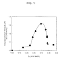
- Fig. 1 shows the relationship between the evaluation results of rolling contact fatigue life (vertical axis: B 10 life ratio) and Ec (horizontal axis: % by mass).
- Ec horizontal axis: % by mass.
- the reason for limiting Ec to produce a steel free of eutectic carbide is that, as described above, the formation of eutectic carbide in steel can cause rolling contact fatigue originating from the eutectic carbide, which causes deterioration in the rolling contact fatigue life characteristics.
- the formation of eutectic carbide can be decreased even with an ingot steel manufactured by ingot casting.
- the present invention is particularly effective when applied to ingot steels manufactured by ingot casting. It is also effective to use ingot steels to manufacture bearing products having a small section to those having a large section.
- Cu, Ni, and Mo can improve the quench hardenability, the strength after tempering, and the rolling contact fatigue life characteristics of steel and can be selectively added in accordance with the strength required (more specifically, any one of Cu, Ni, Mo, Cu + Ni, Cu + Mo, Ni + Mo, and Cu + Ni + Mo can be selectively added).
- the amounts to be added are preferably 0.005% by mass or more for Cu and Ni and 0.01% by mass or more for Mo.
- the addition of more than 0.5% by mass Cu or Mo or more than 1.00% by mass Ni results in deterioration in the machinability of steel.
- Cu, Ni, and Mo are preferably added in amounts equal to or below these upper limits.
- the following components may be added to a bearing steel according to the present invention.
- W, Nb, Ti, Zr, and V can improve the quench hardenability, the strength after tempering, and the rolling contact fatigue life characteristics of steel and can be selectively added in accordance with the strength required (more specifically, any one of W, Nb, Ti, Zr, V, W + Nb, W + Ti, W + Zr, W + V, Nb + Ti, Nb + Zr, Nb + V, Ti + Zr, Ti + V, Zr + V, W + Nb + Ti, W + Nb + Zr, W + Nb + Ti, W + Nb + Zr, W + Nb + V, W + Ti + Zr, W + Ti + V, W + Zr + V, Nb + Ti + Zr, Nb + Ti + V, Nb + Zr + V, Ti + Zr + V, W + Nb + Ti + Zr, W + Nb + Ti + Zr, W + Nb + Ti + Zr, W + Nb + Ti + Zr, W + Nb + Ti + Zr, W
- the amounts to be added are preferably 0.001% by mass or more for W, Nb, Ti, and Zr and 0.002% by mass or more for V.
- W, Nb, Ti, and Zr 0.001% by mass or more for W, Nb, Ti, and Zr
- 0.002% by mass or more for V the addition of more than 0.5% by mass W or V or more than 0.1% by mass of Nb, Ti, or Zr results in deterioration in the machinability of steel.
- these elements are preferably added in amounts equal to or below these upper limits.
- B can improve quench hardenability and thereby increase the strength of steel after tempering and improve the rolling contact fatigue life characteristics of steel.
- B can be added to steel on an as-needed basis. In order to produce these effects, 0.0002% by mass or more of B is preferably added. However, the addition of more than 0.005% by mass B results in deterioration in workability. Thus, 0.0002% to 0.005% by mass B is preferably added.
- any combination of elements of (A), (B), and (C) groups is available. More specifically, an element selected from any one element group may be added, elements selected from each of two element groups may be added, or elements selected from each of all the element groups may be added.
- the components other than the components described above are Fe and incidental impurities.
- the incidental impurities include, but are not limited to, Sn, Sb, As, and Ca.
- a bearing steel having the composition described above is smelted in a vacuum melting furnace or a converter and further by a known refining method, such as a degassing process, and is then formed into a cast billet by ingot casting or continuous casting.
- a known refining method such as a degassing process
- the present invention can be applied to ingot steels (with which large cast billets can be manufactured). Cast billets are subsequently subjected to a forming process, such as rolling or forging, to produce bearing components.
- a steel having a composition listed in Table 3 was smelted by converter refining and a degassing process and was then formed into a cast billet having a size listed in Table 4 by ingot casting or continuous casting.
- the cast billet was heated to a temperature in the range of 1000°C to 1350°C in a furnace and was then forged to have a section size listed in Table 4.
- the presence of eutectic carbide and the rolling contact fatigue life characteristics of the forged product were examined as described below.
- T 1 T 2 denote a side length of a square-forged steel billet: Fig. 2 ) or a D/4 portion and a D/2 portion (D denotes the diameter of a circular-forged steel billet: Fig. 4 ) of a forged steel billet such that the section in the drawing direction became a surface to be observed, etching the sample with 3% nital, and observing the sample with a scanning electron microscope (SEM) at a magnification ratio of 500.
- SEM scanning electron microscope
- the rolling contact fatigue life characteristics are preferably determined in actual use after forging, cutting, quenching, and tempering. However, this requires long term. Thus, the rolling contact fatigue life characteristics were determined with a thrust type rolling contact fatigue machine as described below.
- the disk was then tempered at 170°C for 1.5 hours and was flat-polished to 60 mm ⁇ x 5 mm.
- the test surface was mirror-finished.
- the test specimen thus prepared was subjected to a rolling contact fatigue test under a maximum Hertzian contact stress of 5.8 GPa with a thrust rolling contact fatigue machine in which a steel ball rolled on the circumference of a circle having a diameter of approximately 38 mm.
- Each of the test specimens was sampled from a portion of the forged steel billet corresponding to the bottom of an ingot steel or a continuously casting steel.
- the rolling contact fatigue life characteristics were determined as described below.
- the stress loading frequency when the test specimen underwent detachment was measured for 10 to 15 test specimens.
- the relationship between the cumulative probability and the stress loading frequency was organized using Weibull probability paper. After that, the cumulative probability 10% (hereinafter referred to as B 10 life) was determined. The rolling contact fatigue life characteristics were judged to be improved when the B 10 life was improved by 10% or more with respect to a reference steel (A-1: SUJ2 equivalent steel).
- the machinability is preferably determined in actual processing after forging, cutting, quenching, and tempering. However, this requires long term. Thus, the machinability was determined in a turning test (lathe turning test of the outer surface) as described below.
- the machinability of the test specimen thus prepared was determined with a lathe turning tester.
- the turning test was performed with a superhard (P10) cutting tool without a lubricant at a cutting speed of 120 mm/min, a feed speed of 0.2 m/rev, and a depth of cut of 1.0 mm.
- the amount of time elapsed to the time the flank wear of the tool was 0.2 mm was considered to be the tool life.
- Table 5 shows the presence or absence of eutectic carbide, the rolling contact fatigue life characteristics, and the results of machinability test. It was shown that steels B-1 to B-2, B-4 to B-6, B-8, B-13 to B-19, B-21 to B-22, B-24 to B-26, and B-28 to B-29, which satisfy the composition and Ec according to the present invention, contained no eutectic carbide in the steel and had excellent rolling contact fatigue life characteristics. In contrast, steels B-3, B-7, B-12, and B-23, which have a composition within the scope of the present invention but Ec outside the scope of the present invention, contained eutectic carbide in the steel and had a shortened rolling contact fatigue life.
- Steels B-9 to B-11, B-20, B-27, and B-31 to B-34 which have a composition outside the scope of the present invention, had a shortened rolling contact fatigue life.
- bearing steels having excellent rolling contact fatigue life characteristics can be manufactured at low cost, and industrially very valuable bearing steels can be provided.
Landscapes
- Chemical & Material Sciences (AREA)
- Engineering & Computer Science (AREA)
- Materials Engineering (AREA)
- Mechanical Engineering (AREA)
- Metallurgy (AREA)
- Organic Chemistry (AREA)
- Physics & Mathematics (AREA)
- Thermal Sciences (AREA)
- Crystallography & Structural Chemistry (AREA)
- Rolling Contact Bearings (AREA)
Abstract
Description
- The present invention relates to a bearing steel having excellent rolling contact fatigue life characteristics and suitable as a bearing material for use in automobiles, wind power, transport machines, electrical machines, precision machines, and other general industrial machinery.
- High-carbon chromium steel (JIS G4805 standard SUJ2) has been widely used as a bearing steel of this type. In general, one of the important properties of bearing steels is their excellent rolling contact fatigue life characteristics. It is generally believed that the rolling contact fatigue life of steel is shortened by the presence of a non-metallic inclusion or eutectic carbide in the steel.
- It has been believed in recent studies that non-metallic inclusions in steel are mainly responsible for the decrease in rolling contact fatigue life. Thus, bearing life has been improved by reducing the oxygen content of steel to control the number and size of non-metallic inclusions in the steel.
For example,PTLs 1 and 2 propose techniques for controlling the composition, shape, or distribution of an oxide-based non-metallic inclusion in steel. However, the manufacture of a bearing steel containing a decreased number of non-metallic inclusions requires expensive converter steelmaking machines or extensive modifications of conventional facilities, which entails an immense economic burden. - PTL 3 discloses a technique for improving the rolling contact fatigue life characteristics by controlling the centerline segregation rate of carbon and the oxygen and sulfur contents of steel. However, as described above, a further reduction in oxygen content to manufacture a bearing steel containing a decreased number of non-metallic inclusions requires expensive converter steelmaking machines or extensive modifications of conventional facilities, which entails an immense economic burden.
- Thus, not only the decrease in the number of non-metallic inclusions in steel but also the decrease in the eutectic carbide content of steel have received attention. For example, although a high-carbon chromium steel, which contains 0.95% by mass or more C, is very hard and has high wear resistance, the central portion of a casting steel has a high degree of segregation (hereinafter referred to as centerline segregation), and furthermore enormous eutectic carbide is formed in the casting steel, which shortens the rolling contact fatigue life. Thus, the central portion of the casting steel is removed as a waste or is subjected to diffusion treatment (hereinafter referred to as soaking) for a long period of time to sufficiently eliminate the centerline segregation and the eutectic carbide.
- Regarding such a segregation problem,
PTL 4 discloses a method in which steel is controlled to have specific composition such as C: 0.6% to 1.2% by mass, and the total cross-sectional area of carbide having a thickness of 2 µm or more and, with respect to the center line of a longitudinal cross-section through the shaft center of a wire or rod-shaped rolled steels, existing in a central region within 1/8 x D (D: the width of the longitudinal section) from the axis, including the axis of the longitudinal section, is 0.3% or less of the area of the longitudinal section.PTL 4 also quantitatively shows the influence of the amount of enormous carbide on the rolling contact fatigue life characteristics, indicating the presence of enormous eutectic carbide in steel that shortens the rolling contact fatigue life. - PTL 5 discloses a bearing steel that has a specific composition, such as C: 0.50% to 1.50% by mass and Sb: 0.0010% to 0.0150% by mass, a decreased amount of decarburized layer, and high thermal process productivity. It is an object of PTL 5 to improve thermal process productivity by the addition of Sb to decrease the formation of a decarburized layer in steel and thereby eliminate the cutting or grinding process after the thermal process. However, Sb may be highly toxic to human bodies and should therefore be treated carefully. Furthermore, the addition of Sb results in the condensation of Sb in the central segregation zone, worsening the centerline segregation. A portion containing condensed Sb can be locally hardened to have a different hardness from the base material. The different hardness may induce rolling contact fatigue fracture, shortening the rolling contact fatigue life.
- In order to eliminate centerline segregation in the casting of a high-carbon chromium bearing steel and enormous eutectic carbide formed in the central segregation zone, for example, PTL 6 discloses a method for rolling a casting material into a billet and soaking the billet.
- However, because of nonuniform steel temperature in soaking, a soaking temperature exceeding the solidus line in a portion could initiate melting in the portion again and induce a eutectic reaction, forming further enormous eutectic carbide.
- Thus, in some applications of bearings, low-carbon alloy steel may be used in place of high-carbon chromium steel. For example, case-hardened steel is most commonly used after high-carbon chromium steel. However, case-hardened steel contains 0.23% by mass or less C and moderate amounts of Mn, Cr, Mo, and Ni or the like so as to achieve necessary quench hardenability and mechanical strength. In order to improve fatigue strength, the surface of case-hardened steel is hardened by carburization or carbonitriding.
- For example, PTL 7 discloses a case-hardened steel that can be carburized in a short period of time, wherein the case-hardened steel has a specific chemical composition, such as C: 0.10% to 0.35%, and the activation energy of carbon diffusion in the steel defined by Q = 34140 - 605[%Si] + 183[%Mn] + 136[%Cr] + 122[%Mo] is 34000 kcal or less.
- Likewise, PTL 8 discloses a technique regarding a carburized material that has excellent rolling contact fatigue characteristics, wherein the carburized material has a specific chemical composition, such as C: 0.1% to 0.45%, the austenite grain size number of a carburized layer is 7 or more, the carbon content of the surface ranges from 0.9% to 1.5%, and the retained austenite content of the surface ranges from 25% to 40%.
- Although the carburization or carbonitriding can improve the rolling contact fatigue life characteristics, it may increase the manufacturing costs or decrease the yield because of a large strain or dimension change, thus increasing the product cost.
Some applications of bearing steels require a large section. This requires extensive modifications of carburization or carbonitriding facilities, which entail an immense economic burden. -
- PTL 1: Japanese Unexamined Patent Application Publication No.
1-306542 - PTL 2: Japanese Unexamined Patent Application Publication No.
3-126839 - PTL 3: Japanese Unexamined Patent Application Publication No.
7-127643 - PTL 4: Japanese Patent No.
3007834 - PTL 5: Japanese Unexamined Patent Application Publication No.
5-271866 - PTL 6: Japanese Unexamined Patent Application Publication No.
3-75312 - PTL 7: Japanese Patent No.
4066903 - PTL 8: Japanese Patent No.
4050829 - With a year-by-year increase in the scale of wind power, transport machines, and general industrial machinery, there has been an urgent need to further increase the section of bearing steels. Methods for manufacturing steel ingots are broadly divided into ingot casting and continuous casting. Bearing steels having a small section to a large section, which are hitherto manufactured by continuous casting steel, can be provided by manufacturing ingot casting steel in order to answer the upsizing tendency. However, steels manufactured by the ingot casting (hereinafter referred to as ingot steels) have a particular problem that enormous eutectic carbide is formed in a segregation zone, such as a V-segregation zone or an inverse V-segregation zone. This is because ingot steels have a higher degree of segregation and consequently a higher frequency of enormous eutectic carbide than continuously casting steels. Thus, it is important to decrease the formation of eutectic carbide.
Accordingly, it is an object of the present invention to provide a method for decreasing the formation of eutectic carbide in the segregation zone in bearing steels particularly made of ingot steels, as well as continuously casting steels. - As a result of extensive studies to solve the problems described above, the present inventors have found that the amounts of C, Si, Mn, Cr, and Al added to a conventional bearing steel are limited to a specific range and that a eutectic carbide formation index is newly introduced and is limited to a specific range. Thus, the present inventors found that these limitations can avoid the formation of enormous eutectic carbide in the V-segregation zone or the inverse V-segregation zone, which are particularly problematic in ingot steels, and a bearing steel having excellent rolling contact life characteristics can be provided.
More specifically, the present inventors manufactured a bearing steel made of an ingot steel in which the amounts of C, Si, Mn, Cr, and Al are altered and the eutectic carbide formation index Ec having the formula (1) described below is altered. As a result of extensive studies on the structure and the rolling contact fatigue life characteristics of the bearing steel, the present inventors arrived at the present invention by finding that a steel, even made of an ingot steel, having a composition and Ec in specific ranges can be free of eutectic carbide in the steel and have improved rolling contact fatigue life characteristics. - The aspects of the present invention are as follows:
- 1. A bearing steel having a composition containing
C: 0.56% by mass or more and 0.70% by mass or less,
Si: 0.15% by mass or more and less than 0.50% by mass,
Mn: 0.60% by mass or more and 1.50% by mass or less,
Cr: 0.50% by mass or more and 1.10% by mass or less,
P: 0.025% by mass or less,
S: 0.025% by mass or less,
Al: 0.005% by mass or more and 0.500% by mass or less,
O: 0.0015% by mass or less,
N: 0.0030% by mass or more and 0.015% by mass or less, and
a remainder of Fe and incidental impurities,
wherein eutectic carbide formation index Ec defined by the formula (1) satisfies
wherein
wherein [ ] indicates the amount of component described in parentheses (% by mass). -
- 2. The bearing steel according to 1 described above, wherein the composition further contains one or more selected from
Cu: 0.005% by mass or more and 0.5% by mass or less,
Ni: 0.005% by mass or more and 1.00% by mass or less, and
Mo: 0.01% by mass or more and 0.5% by mass or less. -
- 3. The bearing steel according to 1 or 2 described above, wherein the composition further contains one or more selected from
W: 0.001% by mass or more and 0.5% by mass or less,
Nb: 0.001% by mass or more and 0.1% by mass or less,
Ti: 0.001% by mass or more and 0.1% by mass or less,
Zr: 0.001% by mass or more and 0.1% by mass or less, and
V: 0.002% by mass or more and 0.5% by mass or less. -
- 4. The bearing steel according to any one of 1 to 3 described above, wherein the composition further contains
B: 0.0002% by mass or more and 0.005% by mass or less.
Summarizing these aspects 1 to 4, a bearing steel according to the present invention has a composition containing
C: 0.56% by mass or more and 0.70% by mass or less, Si: 0.15% by mass or more and less than 0.50% by mass, Mn: 0.60% by mass or more and 1.50% by mass or less, Cr: 0.50% by mass or more and 1.10% by mass or less, P: 0.025% by mass or less, S: 0.025% by mass or less, Al: 0.005% by mass or more and 0.500% by mass or less, O: 0.0015% by mass or less, and N: 0.0030% by mass or more and 0.015% by mass or less,
and optionally at least one of (A) to (C):- (A) one or more selected from Cu: 0.005% by mass or more and 0.5% by mass or less, Ni: 0.005% by mass or more and 1.00% by mass or less, and Mo: 0.01% by mass or more and 0.5% by mass or less,
- (B) one or more selected from W: 0.001% by mass or more and 0.5% by mass or less, Nb: 0.001% by mass or more and 0.1% by mass or less, Ti: 0.001% by mass or more and 0.1% by mass or less, Zr: 0.001% by mass or more and 0.1% by mass or less, and V: 0.002% by mass or more and 0.5% by mass or less, and
- (C) B: 0.0002% by mass or more and 0.005% by mass or less,
wherein eutectic carbide formation index Ec defined by the formula (1) satisfies 0 < Ec ≤ 0.25. - In accordance with the present invention, a bearing steel having much better rolling contact fatigue life characteristics than conventional bearing steels can be stably manufactured. In particular, ingot steels can be used to manufacture bearing steels having a small section to those having a large section. The present invention also contributes to the upsizing of wind power generators, transport machines, and general industrial machinery, providing industrially advantageous effects.
-
- [
Fig. 1] Fig. 1 is a graph showing the evaluation result of the rolling contact fatigue life (vertical axis: B10 life ratio) as a function of Ec (horizontal axis: % by mass). - [
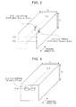
Fig. 2] Fig. 2 is a view illustrating the sampling position and the test surface size in sampling for microstructure observation from a steel billet after square forging. - [
Fig. 3] Fig. 3 is a view illustrating the sampling position and the test specimen size in sampling for the evaluation of rolling contact life from a steel billet after square forging. - [
Fig. 4] Fig. 4 is a view illustrating the sampling position and the test surface size in sampling for microstructure observation from a steel billet after circular forging. - [
Fig. 5] Fig. 5 is a view illustrating the sampling position and the test surface size in sampling for the evaluation of rolling contact life from a steel billet after circular forging. - [
Fig. 6] Fig. 6 is a view illustrating the sampling position and the test specimen size in sampling for the evaluation of machinability from a steel billet after square forging. - [
Fig. 7] Fig. 7 is a view illustrating the sampling position and the test specimen size in sampling for the evaluation of machinability from a steel billet after circular forging. - A bearing steel according to the present invention will be described in detail below.
First, reasons for limiting the percentage of each component of the composition of a bearing steel according to the present invention will be described below. - C can increase the strength of steel and effectively improve the rolling contact fatigue life characteristics of steel. The C content in the present invention is 0.56% by mass or more. On the other hand, the C content of more than 0.70% by mass results in the formation of enormous eutectic carbide during the casting of the material, shortening the rolling contact fatigue life. Thus, the C content is 0.56% by mass or more and 0.70% by mass or less.
- Si can act as a deoxidizing agent, increase the strength of steel owing to solid-solution hardening, and improve the rolling contact fatigue life characteristics of steel. Si is added to produce these effects. In order to produce these effects, 0.15% by mass or more Si is added in the present invention. However, the addition of 0.50% by mass or more Si results in deterioration in the machinability and the forgeability of steel. Si can be bound to oxygen in steel and remain as an oxide in the steel, causing deterioration in the rolling contact fatigue life characteristics. Furthermore, Si condensed in a segregation zone facilitates the formation of eutectic carbide. Thus, the upper limit of Si is less than 0.50% by mass.
- Mn can be added to improve quench hardenability, increase the toughness of steel, and improve the rolling contact fatigue life characteristics of steel. 0.60% by mass or more Mn is added in the present invention. However, the addition of more than 1.50% by mass Mn results in deterioration in machinability. Furthermore, Mn condensed in a segregation zone facilitates the formation of eutectic carbide. Thus, the upper limit of Mn is 1.50% by mass.
- In the same manner as in Mn, Cr can be added to increase the toughness of steel and improve the rolling contact fatigue life characteristics of steel. 0.50% by mass or more Cr is added in the present invention. However, the addition of more than 1.10% by mass Cr results in deterioration in machinability. Thus, the upper limit of Cr is 1.10% by mass.
- P is a detrimental element that can decrease the base material toughness or the rolling contact fatigue life of steel and is preferably decreased as much as possible. In particular, the P content of more than 0.025% by mass results in a significant decrease in base material toughness and rolling contact fatigue life. Thus, the P content is 0.025% by mass or less, preferably 0.020% by mass or less. It is industrially difficult to achieve the P content of 0%. Thus, the P content is often 0.003% by mass or more.
- S is contained in steel as a non-metallic inclusion MnS. Since bearing steels contain a decreased amount of oxide, which can often induce rolling contact fatigue, a large amount of MnS in steel can shorten the rolling contact fatigue life. Thus, S is preferably decreased as much as possible. The S content in the present invention is 0.025% by mass or less, preferably 0.020% by mass or less. It is industrially difficult to achieve the S content of 0%. Thus, the S content is often 0.0001% by mass or more.
- Al can act as a deoxidizing agent, form a nitride and decrease the size of austenite grains, and improve the toughness and the rolling contact fatigue life characteristics. Al is added to produce these effects. In order to produce these effects, 0.005% by mass or more Al is added in the present invention. However, the addition of more than 0.500% by mass Al results in the formation of a coarse oxide type inclusion in steel, causing deterioration in the rolling contact fatigue life characteristics of steel. Furthermore, Al condensed in a segregation zone facilitates the formation of eutectic carbide. Thus, the upper limit of the Al content is 0.500% by mass, preferably 0.450% by mass or less.
- O can be bound to Si or Al to form a hard oxide-based non-metallic inclusion, shortening the rolling contact fatigue life. Thus, O is preferably decreased as much as possible and is 0.0015% by mass or less. It is industrially difficult to achieve the O content of 0%. Thus, the O content is often 0.0003% by mass or more.
- N can be bound to Al to form a nitride-based non-metallic inclusion, decrease the size of austenite grains, and improve the toughness and the rolling contact fatigue life characteristics. Thus, 0.003% by mass or more N is added. However, the addition of more than 0.015% by mass N results in the formation of a large number of nitride-based inclusions in steel, causing deterioration in the rolling contact fatigue life characteristics. This also results in the presence of a large amount of N that does not form a nitride in steel (free N), thus decreasing the toughness of steel. Thus, the upper limit of the N content is 0.015% by mass, preferably 0.010% by mass or less.
- The present inventors smelted steels having various compositions in a vacuum melting furnace. The resulting steel ingot was examined for the presence of eutectic carbide. Regression calculation on the result was performed with various selected sets of parameters (main influential elements). As a result, it was found that the eutectic carbide index Ec defined by the formula (1) must satisfy 0 < Ec ≤ 0.25 as a steel composition with which the formation of eutectic carbide can be decreased.

- The present inventors manufactured bearing steels having the compositions and Ec's listed in Table 1 and examined their rolling contact fatigue life characteristics. The rolling contact fatigue life characteristics were performed by the test method described below in the examples.
In order to examine the presence of eutectic carbide and the influence of the composition and Ec on the rolling contact fatigue life characteristics, bearing steels were manufactured under fixed conditions. More specifically, after smelting in a converter, an ingot steel (ingot) having a 1350 mm x 1250 mm section (top side) and a 1280 x 830 mm section (bottom side) was formed by ingot casting. The ingot steel was forged to have a 550 mm square section. Test specimens for observing formed eutectic carbide illustrated inFig. 2 and rolling contact fatigue test specimens illustrated inFig. 3 were sampled from the forged steel billet. The presence of eutectic carbide, the rolling contact fatigue life characteristics, and the machinability (determined from the tool life ratio) were examine by the test method described below.
Each of the test specimens was sampled from a portion of the forged steel billet corresponding to the bottom of the ingot steel. -
[Table 1] Table 1 (% by mass) Steer No. C Si Mn P S Cr Al O N Ec Note A-1 1.05 0.25 0.45 0.016 0.008 1.45 0.025 0.0010 0.0031 -0.24 Reference steel A-2 0.70 0.46 1.23 0.018 0.005 0.51 0.021 0.0011 0.0030 0.03 Inventive A-3 0.70 0.49 1.50 0.011 0.005 0.51 0.121 0.0010 0.0038 -0.01 Comparative steel A-4 0.62 0.32 0.97 0.010 0.006 0.88 0.024 0.0008 0.0052 0.15 Inventive A-5 0.57 0.16 0.74 0.015 0.003 0.71 0.021 0.0009 0.0049 0.21 Inventive A-6 0.48 0.19 0.58 0.011 0.005 1.09 0.033 0.0009 0.0045 0.31 Comparative steel A-7 0.56 0.22 0.62 0.008 0.002 1.00 0.028 0.0008 0.0036 0.23 Inventive A-8 0.55 0.23 0.63 0.007 0.003 0.95 0.021 0.0009 0.0042 0.24 Comparative steel A-9 0.56 0.16 0.60 0.007 0.003 1.00 0.037 0.0007 0.0035 0.23 Inventive A-10 0.56 0.16 0.58 0.009 0.003 1.05 0.036 0.0008 0.0031 0.23 Comparative steel A-11 0.70 0.50 1.50 0.012 0.003 0.51 0.340 0.0011 0.0042 -0.09 Comparative steel A-12 0.67 0.39 0.95 0.008 0.002 0.56 0.035 0.0010 0.0035 0.07 Inventive - Table 2 shows the evaluation results of rolling contact fatigue life and machinability (determined from the tool life ratio).
Fig. 1 shows the relationship between the evaluation results of rolling contact fatigue life (vertical axis: B10 life ratio) and Ec (horizontal axis: % by mass). As shown in the figure, enormous eutectic carbide is formed in steel when Ec is 0 or less. Even an increase in Ec in this range cannot significantly improve the rolling contact fatigue life relative to the level of a reference material. When Ec is more than 0, eutectic carbide is not formed, and the rolling contact fatigue life is markedly improved. However, Ec of more than 0.25 resulted in a decrease in the amount of C added and consequently a decrease in the strength and the rolling contact fatigue life of steel after quenching. Thus, when Ec is in the range of 0 < Ec ≤ 0.25, eutectic carbide is not formed in steel, and therefore the rolling contact fatigue life characteristics are improved. Even when Ec is within the scope of the present invention, A-8 having a C content outside the scope of the present invention and A-10 having a Mn content outside the scope of the present invention had a decreased strength and consequently a shortened rolling contact fatigue life. - [Table 2]
Table 2 Test results Steel No. Presence of eutectic carbide Ec Rolling contract fatigue life (B10 life ratio) Tool life ratio Note Symbol in Fig. 1 A-1 Yes -0.24 1.00 1.00 Reference steel ● A-2 No 0.03 1.16 1.21 Inventive steel ◆ A-3 Yes -0.01 1.06 1.20 Comparative steel ◆ A-4 No 0.15 1.32 1.22 Inventive steel ◆ A-5 No 0.21 1.25 1.24 Inventive steel ◆ A-6 No 0.31 1.07 1.24 Comparative steel ■ A-7 No 0.23 1.17 1.20 Inventive steel ◆ A-8 No 0.24 1.08 1.20 Comparative steel ▲ A-9 No 0.23 1.16 1.21 Inventive steel ◆ A-10 No 0.23 1.09 1.20 Comparative steel ▲ A-11 Yes -0.09 1.03 1.18 Comparative steel ◆ A-12 No 0.07 1.23 1.22 Inventive steel ◆ - The reason for limiting Ec to produce a steel free of eutectic carbide is that, as described above, the formation of eutectic carbide in steel can cause rolling contact fatigue originating from the eutectic carbide, which causes deterioration in the rolling contact fatigue life characteristics.
- In accordance with the present invention, the formation of eutectic carbide can be decreased even with an ingot steel manufactured by ingot casting. Thus, the present invention is particularly effective when applied to ingot steels manufactured by ingot casting. It is also effective to use ingot steels to manufacture bearing products having a small section to those having a large section.
- In addition to these base components, the following components can appropriately be added.
- Cu, Ni, and Mo can improve the quench hardenability, the strength after tempering, and the rolling contact fatigue life characteristics of steel and can be selectively added in accordance with the strength required (more specifically, any one of Cu, Ni, Mo, Cu + Ni, Cu + Mo, Ni + Mo, and Cu + Ni + Mo can be selectively added). In order to produce such effects, the amounts to be added are preferably 0.005% by mass or more for Cu and Ni and 0.01% by mass or more for Mo. However, the addition of more than 0.5% by mass Cu or Mo or more than 1.00% by mass Ni results in deterioration in the machinability of steel. Thus, Cu, Ni, and Mo are preferably added in amounts equal to or below these upper limits.
- Likewise, in order to increase the strength or improve the rolling contact fatigue life characteristics of steel, in addition to the components described above, the following components may be added to a bearing steel according to the present invention.
- W, Nb, Ti, Zr, and V can improve the quench hardenability, the strength after tempering, and the rolling contact fatigue life characteristics of steel and can be selectively added in accordance with the strength required (more specifically, any one of W, Nb, Ti, Zr, V, W + Nb, W + Ti, W + Zr, W + V, Nb + Ti, Nb + Zr, Nb + V, Ti + Zr, Ti + V, Zr + V, W + Nb + Ti, W + Nb + Zr, W + Nb + V, W + Ti + Zr, W + Ti + V, W + Zr + V, Nb + Ti + Zr, Nb + Ti + V, Nb + Zr + V, Ti + Zr + V, W + Nb + Ti + Zr, W + Nb + Ti + V, W + Nb + Zr + V, W + Ti + Zr + V, Nb + Ti + Zr + V, and W + Nb + Ti + Zr + V can be selectively added). In order to produce such effects, the amounts to be added are preferably 0.001% by mass or more for W, Nb, Ti, and Zr and 0.002% by mass or more for V. However, the addition of more than 0.5% by mass W or V or more than 0.1% by mass of Nb, Ti, or Zr results in deterioration in the machinability of steel. Thus, these elements are preferably added in amounts equal to or below these upper limits.
- B can improve quench hardenability and thereby increase the strength of steel after tempering and improve the rolling contact fatigue life characteristics of steel. B can be added to steel on an as-needed basis. In order to produce these effects, 0.0002% by mass or more of B is preferably added. However, the addition of more than 0.005% by mass B results in deterioration in workability. Thus, 0.0002% to 0.005% by mass B is preferably added.
When an element other than the base components is added, any combination of elements of (A), (B), and (C) groups is available. More specifically, an element selected from any one element group may be added, elements selected from each of two element groups may be added, or elements selected from each of all the element groups may be added. - In a bearing steel according to the present invention, the components other than the components described above are Fe and incidental impurities. Examples of the incidental impurities include, but are not limited to, Sn, Sb, As, and Ca.
- A bearing steel having the composition described above is smelted in a vacuum melting furnace or a converter and further by a known refining method, such as a degassing process, and is then formed into a cast billet by ingot casting or continuous casting. In accordance with the present invention, even when a cast billet is formed by ingot casting by which eutectic carbide is particularly easily precipitated, the formation of eutectic carbide can be prevented. Thus, the present invention can be applied to ingot steels (with which large cast billets can be manufactured). Cast billets are subsequently subjected to a forming process, such as rolling or forging, to produce bearing components.
- A steel having a composition listed in Table 3 was smelted by converter refining and a degassing process and was then formed into a cast billet having a size listed in Table 4 by ingot casting or continuous casting. The cast billet was heated to a temperature in the range of 1000°C to 1350°C in a furnace and was then forged to have a section size listed in Table 4. The presence of eutectic carbide and the rolling contact fatigue life characteristics of the forged product were examined as described below.
- The presence of eutectic carbide was examined by taking a sample for microstructure observation from a (T1/2, T2/2) portion (central portion) and a (T1/2, T2/4) portion (T1 = T2 denote a side length of a square-forged steel billet:
Fig. 2 ) or a D/4 portion and a D/2 portion (D denotes the diameter of a circular-forged steel billet:Fig. 4 ) of a forged steel billet such that the section in the drawing direction became a surface to be observed, etching the sample with 3% nital, and observing the sample with a scanning electron microscope (SEM) at a magnification ratio of 500. The test area was 10 mm x 10 mm. Each test specimen was sampled from a portion of the forged steel billet corresponding to the bottom of an ingot steel. - The rolling contact fatigue life characteristics are preferably determined in actual use after forging, cutting, quenching, and tempering. However, this requires long term. Thus, the rolling contact fatigue life characteristics were determined with a thrust type rolling contact fatigue machine as described below. A 60 mmφ x 5.3 mm disk was cut from a (T1/2, T2/4) portion (T1 = T2 denote a side length of a square-forged steel billet:
Fig. 3 ) or a D/4 portion (D denotes the diameter of a circular-forged steel billet:Fig. 5 ) of a forged steel billet, was heated at 950°C for 20 minutes, and was quenched with an oil at 25°C. The disk was then tempered at 170°C for 1.5 hours and was flat-polished to 60 mmφ x 5 mm. The test surface was mirror-finished. The test specimen thus prepared was subjected to a rolling contact fatigue test under a maximum Hertzian contact stress of 5.8 GPa with a thrust rolling contact fatigue machine in which a steel ball rolled on the circumference of a circle having a diameter of approximately 38 mm. Each of the test specimens was sampled from a portion of the forged steel billet corresponding to the bottom of an ingot steel or a continuously casting steel.
The rolling contact fatigue life characteristics were determined as described below. The stress loading frequency when the test specimen underwent detachment was measured for 10 to 15 test specimens. The relationship between the cumulative probability and the stress loading frequency was organized using Weibull probability paper. After that, thecumulative probability 10% (hereinafter referred to as B10 life) was determined. The rolling contact fatigue life characteristics were judged to be improved when the B10 life was improved by 10% or more with respect to a reference steel (A-1: SUJ2 equivalent steel). - The machinability is preferably determined in actual processing after forging, cutting, quenching, and tempering. However, this requires long term. Thus, the machinability was determined in a turning test (lathe turning test of the outer surface) as described below. A 60 mmφ x 270 mm round bar was cut from a (T1/2, T2/4) portion (T1 = T2 denote a side length of a square-forged steel billet:
Fig. 6 ) or a D/4 portion (D denotes the diameter of a circular-forged steel billet:Fig. 7 ) of a forged steel billet, was heated at 950°C for 20 minutes, and was quenched with an oil at 25°C. The bar was then tempered at 170°C for 1.5 hours. The machinability of the test specimen thus prepared was determined with a lathe turning tester. The turning test was performed with a superhard (P10) cutting tool without a lubricant at a cutting speed of 120 mm/min, a feed speed of 0.2 m/rev, and a depth of cut of 1.0 mm. The amount of time elapsed to the time the flank wear of the tool was 0.2 mm was considered to be the tool life. The degree of reduction in life (tool life ratio = tool life/tool life of SUJ2 equivalent steel) was determined by dividing the tool life for each steel by the tool life for the reference steel (A-1: SUJ2 equivalent steel). The machinability was judged to be improved when the tool life ratio was improved by 15% or more with respect to the reference steel. - [Table 3]

- [Table 4]
Table 4 Billet Size after Casting and after Forging Steel No. Section of billet (mm) Section after forging (mm) Heating temperature (°C) Note Top Bottom Material Shape*1 Size*2 A-1 1350 × 1250 1280 × 830 Ingot steel □ 550 1150 Reference steel B-1 1330 × 1230 1280 × 860 Ingot steel □ 700 1150 Inventive steel B-2 1100 × 1100 860 × 860 Ingot steel □ 650 1100 Inventive steel B-3 1000 × 1000 700 × 700 Ingot steel O 550 1150 Comparative steel B-4 1250 × 1150 1180 × 730 Ingot steel O 600 1150 Inventive steel B-5 1450 × 1350 1380 × 930 Ingot steel O 750 1100 Inventive steel B-6 900 × 900 700 × 700 Ingot steel O 450 1250 Inventive steel B-7 1330 × 1230 1280 × 860 Ingot steel O 600 1050 Comparative steel B-8 1330 × 1230 1280 × 860 Ingot steel O 600 1000 Inventive steel B-9 1100 × 1100 860 × 860 Ingot steel □ 450 1150 Comparative steel B-10 1450 × 1350 1380 × 930 Ingot steel □ 750 1050 Comparative steel B-11 1450 × 1350 1380 × 930 Ingot steel O 750 1150 Comparative steel B-12 900 × 900 700 × 700 Ingot steel O 450 1100 Comparative steel B-13 1330 × 1230 1280 × 860 Ingot steel O 800 1200 Inventive steel B-14 1330 × 1230 1280 × 860 Ingot steel □ 700 1250 Inventive steel B-15 1450 × 1350 1380 × 930 Ingot steel □ 600 1150 Inventive steel B-16 1450 × 1350 1380 × 930 Ingot steel O 600 1150 Inventive steel B-17 1100 × 1100 860 × 860 Ingot steel □ 450 1350 Inventive steel B-18 1250 × 1150 1180 × 730 Ingot steel O 500 1000 Inventive steel B-19 1100 × 1100 860 × 860 Ingot steel O 400 1050 Inventive steel B-20 1250 × 1150 1180 × 730 Ingot steel □ 550 1100 Comparative steel B-21 1400 × 300 1400 × 300 Continuously casted steel □ 450 1150 Inventive steel B-22 1400 × 300 1400 × 300 Continuously casted steel □ 600 1200 Inventive steel B-23 1400 × 300 1400 × 300 Continuously casted steel □ 450 1100 Comparative steel B-24 1400 × 300 1400 × 300 Continuously casted steel □ 550 1100 Inventive steel B-25 1400 × 300 1400 × 300 Continuously casted steel O 650 1150 Inventive steel B-26 1400 × 300 1400 × 300 Continuously casted steel O 600 1150 Inventive steel B-27 1400 × 300 1400 × 300 Continuously casted steel □ 550 1150 Comparative steel B-28 1330 × 1230 1280 × 860 Ingot steel □ 650 1270 Inventive steel B-29 1330 × 1230 1280 × 860 Ingot steel □ 650 1250 Inventive steel B-30 1330 × 1230 1280 × 860 Ingot steel □ 650 1250 Comparative steel B-31 1330 × 1230 1280 × 860 Ingot steel □ 650 1250 Comparative steel B-32 1330 × 1230 1280 × 860 Ingot steel □ 650 1250 Comparative steel B-33 1330 × 1230 1280 × 860 Ingot steel □ 650 1250 Comparative steel B-34 1330 × 1230 1280 × 860 Ingot steel □ 650 1250 Comparative steel *1: O denotes round forging, denotes square forging.
*2: Diameter for round forging, Side length for square forging - Table 5 shows the presence or absence of eutectic carbide, the rolling contact fatigue life characteristics, and the results of machinability test. It was shown that steels B-1 to B-2, B-4 to B-6, B-8, B-13 to B-19, B-21 to B-22, B-24 to B-26, and B-28 to B-29, which satisfy the composition and Ec according to the present invention, contained no eutectic carbide in the steel and had excellent rolling contact fatigue life characteristics. In contrast, steels B-3, B-7, B-12, and B-23, which have a composition within the scope of the present invention but Ec outside the scope of the present invention, contained eutectic carbide in the steel and had a shortened rolling contact fatigue life. Steels B-9 to B-11, B-20, B-27, and B-31 to B-34, which have a composition outside the scope of the present invention, had a shortened rolling contact fatigue life. Steel B-30, which has Ec within the scope of the present invention but a Cr content outside the scope of the present invention, had insufficient machinability.
- [Table 5]
Table 5 Test results Steel No. Presence of eutectic carbide Ec Rolling contact fatigue life (B10 life ratio) Tool life ratio Note A-1 Yes -0.24 1.00 1.00 Reference steel B-1 No 0.14 1.22 1.21 Inventive steel B-2 No 0.17 1.18 1.21 Inventive steel B-3 Yes -0.13 1.02 1.19 Comparative steel B-4 No 0.19 1.15 1.22 Inventive steel B-5 No 0.10 1.25 1.23 Inventive steel B-6 No 0.16 1.20 1.22 Inventive steel B-7 Yes -0.01 1.09 1.18 Comparative steel B-8 No 0.17 1.18 1.23 Inventive steel B-9 No 0.27 1.09 1.25 Comparative steel B-10 Yes -0.14 1.05 1.12 Comparative steel B-11 No 0.11 1.08 1.20 Comparative steel B-12 Yes -0.03 1.08 1.21 Comparative steel B-13 No 0.12 1.17 1.21 Inventive steel B-14 No 0.06 1.13 1.19 Inventive steel B-15 No 0.16 1.23 1.23 Inventive steel B-16 No 0.09 1.20 1.21 Inventive steel B-17 No 0.09 1.19 1.22 Inventive steel B-18 No 0.20 1.12 1.17 Inventive steel B-19 No 0.21 1.12 1.23 Inventive steel B-20 Yes -0.04 1.08 1.13 Comparative steel B-21 No 0.13 1.15 1.22 Inventive steel B-22 No 0.20 1.12 1.23 Inventive steel B-23 Yes -0.01 1.08 1.20 Comparative steel B-24 No 0.17 1.18 1.22 Inventive steel B-25 No 0.12 1.19 1.20 Inventive steel B-26 No 0.08 1.13 1.20 Inventive steel B-27 Yes -0.24 1.05 0.99 Comparative steel B-28 No 0.13 1.17 1.22 Inventive steel B-29 No 0.15 1.21 1.22 Inventive steel B-30 No 0.11 1.15 1.12 Comparative steel B-31 No 0.07 1.08 1.21 Comparative steel B-32 Yes -0.03 1.07 1.16 Comparative steel B-33 No 0.17 1.08 1.22 Comparative steel B-34 No 0.16 1.07 1.19 Comparative steel - In accordance with the present invention, bearing steels having excellent rolling contact fatigue life characteristics can be manufactured at low cost, and industrially very valuable bearing steels can be provided.
Claims (4)
- A bearing steel having a composition comprising:C: 0.56% by mass or more and 0.70% by mass or less,Si: 0.15% by mass or more and less than 0.50% by mass,Mn: 0.60% by mass or more and 1.50% by mass or less,Cr: 0.50% by mass or more and 1.10% by mass or less,P: 0.025% by mass or less,S: 0.025% by mass or less,Al: 0.005% by mass or more and 0.500% by mass or less,O: 0.0015% by mass or less,N: 0.0030% by mass or more and 0.015% by mass or less, anda remainder of Fe and incidental impurities,wherein eutectic carbide formation index Ec defined by the formula (1) satisfies

wherein wherein [ ] indicates the amount of component described in parentheses (% by mass).
 - The bearing steel according to Claim 1, wherein the composition further contains one or more selected from
Cu: 0.005% by mass or more and 0.5% by mass or less,
Ni: 0.005% by mass or more and 1.00% by mass or less, and
Mo: 0.01% by mass or more and 0.5% by mass or less. - The bearing steel according to Claim 1 or 2, wherein the composition further contains one or more selected from
W: 0.001% by mass or more and 0.5% by mass or less,
Nb: 0.001% by mass or more and 0.1% by mass or less,
Ti: 0.001% by mass or more and 0.1% by mass or less,
Zr: 0.001% by mass or more and 0.1% by mass or less, and
V: 0.002% by mass or more and 0.5% by mass or less. - The bearing steel according to any one of Claims 1 to 3, wherein the composition further contains
B: 0.0002% by mass or more and 0.005% by mass or less.
Applications Claiming Priority (3)
| Application Number | Priority Date | Filing Date | Title |
|---|---|---|---|
| JP2009272929 | 2009-11-30 | ||
| JP2010242668 | 2010-10-28 | ||
| PCT/JP2010/071778 WO2011065592A1 (en) | 2009-11-30 | 2010-11-30 | Bearing steel |
Publications (3)
| Publication Number | Publication Date |
|---|---|
| EP2508637A1 true EP2508637A1 (en) | 2012-10-10 |
| EP2508637A4 EP2508637A4 (en) | 2013-10-02 |
| EP2508637B1 EP2508637B1 (en) | 2015-05-06 |
Family
ID=44066694
Family Applications (1)
| Application Number | Title | Priority Date | Filing Date |
|---|---|---|---|
| EP20100833433 Active EP2508637B1 (en) | 2009-11-30 | 2010-11-30 | Bearing steel |
Country Status (6)
| Country | Link |
|---|---|
| US (1) | US20130017117A1 (en) |
| EP (1) | EP2508637B1 (en) |
| JP (1) | JP4775506B1 (en) |
| KR (1) | KR101482365B1 (en) |
| CN (1) | CN102639736B (en) |
| WO (1) | WO2011065592A1 (en) |
Cited By (3)
| Publication number | Priority date | Publication date | Assignee | Title |
|---|---|---|---|---|
| EP2508638A1 (en) * | 2009-11-30 | 2012-10-10 | JFE Steel Corporation | Ingot for bearing, and process for producing bearing steel |
| EP2612939A1 (en) * | 2010-08-31 | 2013-07-10 | JFE Steel Corporation | Bearing steel and ingot material for bearing having high rolling fatigue life characteristics and method for manufacturing same |
| RU2569435C1 (en) * | 2014-08-25 | 2015-11-27 | Федеральное государственное унитарное предприятие "Всероссийский научно-исследовательский институт авиационных материалов" (ФГУП "ВИАМ") | Heat-resistant bearing steel |
Families Citing this family (13)
| Publication number | Priority date | Publication date | Assignee | Title |
|---|---|---|---|---|
| US9732395B2 (en) | 2011-09-30 | 2017-08-15 | Jfe Steel Corporation | Ingot for bearing and production process |
| JP6102183B2 (en) * | 2011-11-09 | 2017-03-29 | Jfeスチール株式会社 | Induction hardening steel and manufacturing method thereof |
| CN103667927A (en) * | 2013-11-07 | 2014-03-26 | 安徽省智汇电气技术有限公司 | High-strength high-carbon steel material for pump bearings and preparation method thereof |
| CN103643113A (en) * | 2013-11-12 | 2014-03-19 | 铜陵市肆得科技有限责任公司 | Tungsten dysprosium-containing manganese steel material for bearings and preparation method thereof |
| CN104178698B (en) * | 2014-09-01 | 2016-03-23 | 山东钢铁股份有限公司 | A kind of preparation method of bearing steel |
| CN104805370B (en) * | 2015-05-05 | 2017-10-03 | 南通莱必特轴承有限公司 | A kind of bearing |
| CN104805349B (en) * | 2015-05-05 | 2016-09-07 | 南通莱必特轴承有限公司 | The preparation method of bearing material |
| CN106498304B (en) * | 2016-09-12 | 2017-12-29 | 北京工业大学 | A kind of corrosion resisting bearing and preparation method thereof |
| CN106591546A (en) * | 2016-12-13 | 2017-04-26 | 椿中岛机械(太仓)有限公司 | Rapid inspection method for bearing steel spheroidizing annealing material carbon scarcity and decarburization |
| CN107649674B (en) * | 2017-08-14 | 2019-04-02 | 天津工业职业学院 | A kind of powder metallurgy wear resistant automobile bearing and preparation method thereof |
| CN107761003A (en) * | 2017-09-20 | 2018-03-06 | 上海汽车粉末冶金有限公司 | The powder metallurgy sintered method of bearing cap |
| CN113088639B (en) * | 2021-03-30 | 2023-05-23 | 江西红睿马钢管股份有限公司 | Bearing steel pipe inspection quality control method for cold rolling and expanding bearing |
| CN118516619A (en) * | 2023-02-17 | 2024-08-20 | 宝山钢铁股份有限公司 | Bearing steel for vehicle hub and manufacturing method thereof |
Citations (3)
| Publication number | Priority date | Publication date | Assignee | Title |
|---|---|---|---|---|
| JPH0254739A (en) * | 1988-08-16 | 1990-02-23 | Kobe Steel Ltd | Bearing steel having excellent workability |
| JPH0892687A (en) * | 1994-09-22 | 1996-04-09 | Kobe Steel Ltd | High strength and high toughness non-heattreated steel for hot forging and its production |
| EP2508638A1 (en) * | 2009-11-30 | 2012-10-10 | JFE Steel Corporation | Ingot for bearing, and process for producing bearing steel |
Family Cites Families (18)
| Publication number | Priority date | Publication date | Assignee | Title |
|---|---|---|---|---|
| JPS58214081A (en) | 1982-06-04 | 1983-12-13 | Hitachi Ltd | Solenoid valve driving device |
| JPH03163153A (en) | 1982-12-28 | 1991-07-15 | Mitsubishi Rayon Co Ltd | Multilayered polymer resin composition |
| JPH01306542A (en) | 1988-05-31 | 1989-12-11 | Sanyo Special Steel Co Ltd | Steel for bearing in which composition of inclusions is regulated |
| JPH0375312A (en) | 1989-08-17 | 1991-03-29 | Daido Steel Co Ltd | Method for soaking bearing steel |
| JP3018355B2 (en) | 1989-10-11 | 2000-03-13 | 日本精工株式会社 | Bearing steel and rolling bearings |
| JPH03297465A (en) | 1990-04-16 | 1991-12-27 | Morisaki Kogei Kk | Decubitus preventing pad |
| JPH04349A (en) * | 1990-04-16 | 1992-01-06 | Kobe Steel Ltd | Bearing steel excellent in workability and rolling fatigue characteristic |
| JP2956324B2 (en) * | 1991-10-24 | 1999-10-04 | 株式会社神戸製鋼所 | Bearing steel with excellent workability and rolling fatigue |
| JP3233674B2 (en) | 1992-03-25 | 2001-11-26 | 川崎製鉄株式会社 | Bearing steel |
| JPH07127643A (en) | 1993-10-29 | 1995-05-16 | Nippon Seiko Kk | Rolling bearing |
| JPH08311607A (en) * | 1995-05-16 | 1996-11-26 | Sumitomo Metal Ind Ltd | Low strain carburized gear excellent in deddendum bending strength and its production |
| JP4114218B2 (en) * | 1996-09-19 | 2008-07-09 | 日本精工株式会社 | Rolling bearing |
| JP3909902B2 (en) * | 1996-12-17 | 2007-04-25 | 株式会社小松製作所 | Steel parts for high surface pressure resistance and method for producing the same |
| JP3426495B2 (en) * | 1998-04-09 | 2003-07-14 | 山陽特殊製鋼株式会社 | Long-life bearing steel excellent in delayed fracture resistance and method of manufacturing the same |
| JP4252837B2 (en) * | 2003-04-16 | 2009-04-08 | Jfeスチール株式会社 | Steel material with excellent rolling fatigue life and method for producing the same |
| KR100845633B1 (en) * | 2004-04-28 | 2008-07-10 | 제이에프이 스틸 가부시키가이샤 | Component for machine structural use and method for making the same |
| CN101376948B (en) * | 2007-08-27 | 2011-03-30 | 宝山钢铁股份有限公司 | Low-cost high-purity medium carbon bearing steel for automobile hub and manufacturing method thereof |
| JP5463662B2 (en) * | 2008-03-10 | 2014-04-09 | Jfeスチール株式会社 | Bearing steel excellent in rolling fatigue characteristics and manufacturing method thereof |
-
2010
- 2010-11-30 WO PCT/JP2010/071778 patent/WO2011065592A1/en active Application Filing
- 2010-11-30 US US13/512,668 patent/US20130017117A1/en not_active Abandoned
- 2010-11-30 KR KR20127016345A patent/KR101482365B1/en active IP Right Grant
- 2010-11-30 CN CN2010800542749A patent/CN102639736B/en active Active
- 2010-11-30 EP EP20100833433 patent/EP2508637B1/en active Active
- 2010-11-30 JP JP2010267781A patent/JP4775506B1/en active Active
Patent Citations (3)
| Publication number | Priority date | Publication date | Assignee | Title |
|---|---|---|---|---|
| JPH0254739A (en) * | 1988-08-16 | 1990-02-23 | Kobe Steel Ltd | Bearing steel having excellent workability |
| JPH0892687A (en) * | 1994-09-22 | 1996-04-09 | Kobe Steel Ltd | High strength and high toughness non-heattreated steel for hot forging and its production |
| EP2508638A1 (en) * | 2009-11-30 | 2012-10-10 | JFE Steel Corporation | Ingot for bearing, and process for producing bearing steel |
Non-Patent Citations (1)
| Title |
|---|
| See also references of WO2011065592A1 * |
Cited By (6)
| Publication number | Priority date | Publication date | Assignee | Title |
|---|---|---|---|---|
| EP2508638A1 (en) * | 2009-11-30 | 2012-10-10 | JFE Steel Corporation | Ingot for bearing, and process for producing bearing steel |
| EP2508638A4 (en) * | 2009-11-30 | 2013-07-24 | Jfe Steel Corp | Ingot for bearing, and process for producing bearing steel |
| EP2612939A1 (en) * | 2010-08-31 | 2013-07-10 | JFE Steel Corporation | Bearing steel and ingot material for bearing having high rolling fatigue life characteristics and method for manufacturing same |
| EP2612939A4 (en) * | 2010-08-31 | 2014-08-13 | Jfe Steel Corp | Bearing steel and ingot material for bearing having high rolling fatigue life characteristics and method for manufacturing same |
| US9139887B2 (en) | 2010-08-31 | 2015-09-22 | Jfe Steel Corporation | Bearing steel and ingot material for bearing having excellent rolling contact fatigue life characteristics and method for manufacturing the same |
| RU2569435C1 (en) * | 2014-08-25 | 2015-11-27 | Федеральное государственное унитарное предприятие "Всероссийский научно-исследовательский институт авиационных материалов" (ФГУП "ВИАМ") | Heat-resistant bearing steel |
Also Published As
| Publication number | Publication date |
|---|---|
| US20130017117A1 (en) | 2013-01-17 |
| KR101482365B1 (en) | 2015-01-13 |
| CN102639736A (en) | 2012-08-15 |
| CN102639736B (en) | 2013-11-27 |
| WO2011065592A1 (en) | 2011-06-03 |
| EP2508637B1 (en) | 2015-05-06 |
| JP2012107308A (en) | 2012-06-07 |
| EP2508637A4 (en) | 2013-10-02 |
| JP4775506B1 (en) | 2011-09-21 |
| KR20120084816A (en) | 2012-07-30 |
Similar Documents
| Publication | Publication Date | Title |
|---|---|---|
| EP2508637B1 (en) | Bearing steel | |
| EP2508638B1 (en) | Forged steel bar for bearings and process for producing it | |
| EP2966189B1 (en) | Semi-finished material for induction hardened component and method for producing same | |
| US8475605B2 (en) | Surface layer-hardened steel part and method of manufacturing the same | |
| EP3088550B1 (en) | Production method of carburized steel component and carburized steel component | |
| KR101396898B1 (en) | Bearing steel and ingot material for bearing having excellent rolling contact fatigue life characteristics and method for manufacturing the same | |
| EP2762587A1 (en) | Ingot for bearing and production process | |
| EP3382050A1 (en) | Steel, carburized steel component, and carburized steel component production method | |
| WO2013161623A1 (en) | Case hardening steel material | |
| JP4502929B2 (en) | Case hardening steel with excellent rolling fatigue characteristics and grain coarsening prevention characteristics | |
| JP5786815B2 (en) | Steel for carburized or carbonitrided parts | |
| CN110651060B (en) | Steel and component | |
| KR100629217B1 (en) | Steel for case hardening bearing excellent in toughness and rolling fatigue life in quasi-high temperature region | |
| JP5077814B2 (en) | Shaft and manufacturing method thereof | |
| JP7545949B2 (en) | Steel material, steel part, and manufacturing method of steel part | |
| JPH11335732A (en) | Manufacture of steel material for soft-nitriding, and soft-nitrided parts using the steel material | |
| JP2005336560A (en) | High-carbon steel sheet for precision-blanked parts, and precision-blanked parts | |
| JP3233792B2 (en) | Bearing steel with excellent microstructure change delay characteristics due to cyclic stress loading and heat treatment productivity |
Legal Events
| Date | Code | Title | Description |
|---|---|---|---|
| PUAI | Public reference made under article 153(3) epc to a published international application that has entered the european phase |
Free format text: ORIGINAL CODE: 0009012 |
|
| 17P | Request for examination filed |
Effective date: 20120625 |
|
| AK | Designated contracting states |
Kind code of ref document: A1 Designated state(s): AL AT BE BG CH CY CZ DE DK EE ES FI FR GB GR HR HU IE IS IT LI LT LU LV MC MK MT NL NO PL PT RO RS SE SI SK SM TR |
|
| DAX | Request for extension of the european patent (deleted) | ||
| RAP1 | Party data changed (applicant data changed or rights of an application transferred) |
Owner name: JFE STEEL CORPORATION Owner name: NTN CORPORATION |
|
| A4 | Supplementary search report drawn up and despatched |
Effective date: 20130829 |
|
| RIC1 | Information provided on ipc code assigned before grant |
Ipc: C22C 38/22 20060101ALI20130823BHEP Ipc: C22C 38/04 20060101ALI20130823BHEP Ipc: C22C 38/54 20060101ALI20130823BHEP Ipc: C21D 9/40 20060101ALI20130823BHEP Ipc: C22C 38/06 20060101ALI20130823BHEP Ipc: C22C 38/40 20060101ALI20130823BHEP Ipc: C22C 38/18 20060101ALI20130823BHEP Ipc: C22C 38/20 20060101ALI20130823BHEP Ipc: F16C 33/64 20060101ALI20130823BHEP Ipc: F16C 33/62 20060101ALI20130823BHEP Ipc: C22C 38/00 20060101AFI20130823BHEP Ipc: C22C 38/02 20060101ALI20130823BHEP |
|
| GRAP | Despatch of communication of intention to grant a patent |
Free format text: ORIGINAL CODE: EPIDOSNIGR1 |
|
| INTG | Intention to grant announced |
Effective date: 20141202 |
|
| GRAS | Grant fee paid |
Free format text: ORIGINAL CODE: EPIDOSNIGR3 |
|
| GRAA | (expected) grant |
Free format text: ORIGINAL CODE: 0009210 |
|
| AK | Designated contracting states |
Kind code of ref document: B1 Designated state(s): AL AT BE BG CH CY CZ DE DK EE ES FI FR GB GR HR HU IE IS IT LI LT LU LV MC MK MT NL NO PL PT RO RS SE SI SK SM TR |
|
| REG | Reference to a national code |
Ref country code: GB Ref legal event code: FG4D |
|
| REG | Reference to a national code |
Ref country code: CH Ref legal event code: EP |
|
| REG | Reference to a national code |
Ref country code: IE Ref legal event code: FG4D |
|
| REG | Reference to a national code |
Ref country code: AT Ref legal event code: REF Ref document number: 725760 Country of ref document: AT Kind code of ref document: T Effective date: 20150615 |
|
| REG | Reference to a national code |
Ref country code: DE Ref legal event code: R096 Ref document number: 602010024575 Country of ref document: DE Effective date: 20150618 |
|
| REG | Reference to a national code |
Ref country code: AT Ref legal event code: MK05 Ref document number: 725760 Country of ref document: AT Kind code of ref document: T Effective date: 20150506 |
|
| REG | Reference to a national code |
Ref country code: NL Ref legal event code: MP Effective date: 20150506 |
|
| REG | Reference to a national code |
Ref country code: LT Ref legal event code: MG4D |
|
| PG25 | Lapsed in a contracting state [announced via postgrant information from national office to epo] |
Ref country code: LT Free format text: LAPSE BECAUSE OF FAILURE TO SUBMIT A TRANSLATION OF THE DESCRIPTION OR TO PAY THE FEE WITHIN THE PRESCRIBED TIME-LIMIT Effective date: 20150506 Ref country code: NO Free format text: LAPSE BECAUSE OF FAILURE TO SUBMIT A TRANSLATION OF THE DESCRIPTION OR TO PAY THE FEE WITHIN THE PRESCRIBED TIME-LIMIT Effective date: 20150806 Ref country code: FI Free format text: LAPSE BECAUSE OF FAILURE TO SUBMIT A TRANSLATION OF THE DESCRIPTION OR TO PAY THE FEE WITHIN THE PRESCRIBED TIME-LIMIT Effective date: 20150506 Ref country code: PT Free format text: LAPSE BECAUSE OF FAILURE TO SUBMIT A TRANSLATION OF THE DESCRIPTION OR TO PAY THE FEE WITHIN THE PRESCRIBED TIME-LIMIT Effective date: 20150907 Ref country code: ES Free format text: LAPSE BECAUSE OF FAILURE TO SUBMIT A TRANSLATION OF THE DESCRIPTION OR TO PAY THE FEE WITHIN THE PRESCRIBED TIME-LIMIT Effective date: 20150506 Ref country code: HR Free format text: LAPSE BECAUSE OF FAILURE TO SUBMIT A TRANSLATION OF THE DESCRIPTION OR TO PAY THE FEE WITHIN THE PRESCRIBED TIME-LIMIT Effective date: 20150506 |
|
| REG | Reference to a national code |
Ref country code: FR Ref legal event code: PLFP Year of fee payment: 6 |
|
| PG25 | Lapsed in a contracting state [announced via postgrant information from national office to epo] |
Ref country code: AT Free format text: LAPSE BECAUSE OF FAILURE TO SUBMIT A TRANSLATION OF THE DESCRIPTION OR TO PAY THE FEE WITHIN THE PRESCRIBED TIME-LIMIT Effective date: 20150506 Ref country code: RS Free format text: LAPSE BECAUSE OF FAILURE TO SUBMIT A TRANSLATION OF THE DESCRIPTION OR TO PAY THE FEE WITHIN THE PRESCRIBED TIME-LIMIT Effective date: 20150506 Ref country code: LV Free format text: LAPSE BECAUSE OF FAILURE TO SUBMIT A TRANSLATION OF THE DESCRIPTION OR TO PAY THE FEE WITHIN THE PRESCRIBED TIME-LIMIT Effective date: 20150506 Ref country code: GR Free format text: LAPSE BECAUSE OF FAILURE TO SUBMIT A TRANSLATION OF THE DESCRIPTION OR TO PAY THE FEE WITHIN THE PRESCRIBED TIME-LIMIT Effective date: 20150807 Ref country code: BG Free format text: LAPSE BECAUSE OF FAILURE TO SUBMIT A TRANSLATION OF THE DESCRIPTION OR TO PAY THE FEE WITHIN THE PRESCRIBED TIME-LIMIT Effective date: 20150806 Ref country code: IS Free format text: LAPSE BECAUSE OF FAILURE TO SUBMIT A TRANSLATION OF THE DESCRIPTION OR TO PAY THE FEE WITHIN THE PRESCRIBED TIME-LIMIT Effective date: 20150906 |
|
| PG25 | Lapsed in a contracting state [announced via postgrant information from national office to epo] |
Ref country code: EE Free format text: LAPSE BECAUSE OF FAILURE TO SUBMIT A TRANSLATION OF THE DESCRIPTION OR TO PAY THE FEE WITHIN THE PRESCRIBED TIME-LIMIT Effective date: 20150506 Ref country code: DK Free format text: LAPSE BECAUSE OF FAILURE TO SUBMIT A TRANSLATION OF THE DESCRIPTION OR TO PAY THE FEE WITHIN THE PRESCRIBED TIME-LIMIT Effective date: 20150506 |
|
| REG | Reference to a national code |
Ref country code: DE Ref legal event code: R097 Ref document number: 602010024575 Country of ref document: DE |
|
| PG25 | Lapsed in a contracting state [announced via postgrant information from national office to epo] |
Ref country code: CZ Free format text: LAPSE BECAUSE OF FAILURE TO SUBMIT A TRANSLATION OF THE DESCRIPTION OR TO PAY THE FEE WITHIN THE PRESCRIBED TIME-LIMIT Effective date: 20150506 Ref country code: SK Free format text: LAPSE BECAUSE OF FAILURE TO SUBMIT A TRANSLATION OF THE DESCRIPTION OR TO PAY THE FEE WITHIN THE PRESCRIBED TIME-LIMIT Effective date: 20150506 Ref country code: RO Free format text: LAPSE BECAUSE OF NON-PAYMENT OF DUE FEES Effective date: 20150506 Ref country code: PL Free format text: LAPSE BECAUSE OF FAILURE TO SUBMIT A TRANSLATION OF THE DESCRIPTION OR TO PAY THE FEE WITHIN THE PRESCRIBED TIME-LIMIT Effective date: 20150506 |
|
| PLBE | No opposition filed within time limit |
Free format text: ORIGINAL CODE: 0009261 |
|
| STAA | Information on the status of an ep patent application or granted ep patent |
Free format text: STATUS: NO OPPOSITION FILED WITHIN TIME LIMIT |
|
| 26N | No opposition filed |
Effective date: 20160209 |
|
| PG25 | Lapsed in a contracting state [announced via postgrant information from national office to epo] |
Ref country code: IT Free format text: LAPSE BECAUSE OF FAILURE TO SUBMIT A TRANSLATION OF THE DESCRIPTION OR TO PAY THE FEE WITHIN THE PRESCRIBED TIME-LIMIT Effective date: 20150506 |
|
| PG25 | Lapsed in a contracting state [announced via postgrant information from national office to epo] |
Ref country code: SI Free format text: LAPSE BECAUSE OF FAILURE TO SUBMIT A TRANSLATION OF THE DESCRIPTION OR TO PAY THE FEE WITHIN THE PRESCRIBED TIME-LIMIT Effective date: 20150506 |
|
| PG25 | Lapsed in a contracting state [announced via postgrant information from national office to epo] |
Ref country code: LU Free format text: LAPSE BECAUSE OF FAILURE TO SUBMIT A TRANSLATION OF THE DESCRIPTION OR TO PAY THE FEE WITHIN THE PRESCRIBED TIME-LIMIT Effective date: 20151130 Ref country code: MC Free format text: LAPSE BECAUSE OF FAILURE TO SUBMIT A TRANSLATION OF THE DESCRIPTION OR TO PAY THE FEE WITHIN THE PRESCRIBED TIME-LIMIT Effective date: 20150506 |
|
| REG | Reference to a national code |
Ref country code: CH Ref legal event code: PL |
|
| PG25 | Lapsed in a contracting state [announced via postgrant information from national office to epo] |
Ref country code: LI Free format text: LAPSE BECAUSE OF NON-PAYMENT OF DUE FEES Effective date: 20151130 Ref country code: CH Free format text: LAPSE BECAUSE OF NON-PAYMENT OF DUE FEES Effective date: 20151130 |
|
| REG | Reference to a national code |
Ref country code: IE Ref legal event code: MM4A |
|
| PG25 | Lapsed in a contracting state [announced via postgrant information from national office to epo] |
Ref country code: BE Free format text: LAPSE BECAUSE OF FAILURE TO SUBMIT A TRANSLATION OF THE DESCRIPTION OR TO PAY THE FEE WITHIN THE PRESCRIBED TIME-LIMIT Effective date: 20150506 |
|
| REG | Reference to a national code |
Ref country code: FR Ref legal event code: PLFP Year of fee payment: 7 |
|
| PG25 | Lapsed in a contracting state [announced via postgrant information from national office to epo] |
Ref country code: IE Free format text: LAPSE BECAUSE OF NON-PAYMENT OF DUE FEES Effective date: 20151130 |
|
| PG25 | Lapsed in a contracting state [announced via postgrant information from national office to epo] |
Ref country code: SM Free format text: LAPSE BECAUSE OF FAILURE TO SUBMIT A TRANSLATION OF THE DESCRIPTION OR TO PAY THE FEE WITHIN THE PRESCRIBED TIME-LIMIT Effective date: 20150506 Ref country code: HU Free format text: LAPSE BECAUSE OF FAILURE TO SUBMIT A TRANSLATION OF THE DESCRIPTION OR TO PAY THE FEE WITHIN THE PRESCRIBED TIME-LIMIT; INVALID AB INITIO Effective date: 20101130 |
|
| PG25 | Lapsed in a contracting state [announced via postgrant information from national office to epo] |
Ref country code: NL Free format text: LAPSE BECAUSE OF FAILURE TO SUBMIT A TRANSLATION OF THE DESCRIPTION OR TO PAY THE FEE WITHIN THE PRESCRIBED TIME-LIMIT Effective date: 20150506 Ref country code: CY Free format text: LAPSE BECAUSE OF FAILURE TO SUBMIT A TRANSLATION OF THE DESCRIPTION OR TO PAY THE FEE WITHIN THE PRESCRIBED TIME-LIMIT Effective date: 20150506 Ref country code: SE Free format text: LAPSE BECAUSE OF FAILURE TO SUBMIT A TRANSLATION OF THE DESCRIPTION OR TO PAY THE FEE WITHIN THE PRESCRIBED TIME-LIMIT Effective date: 20150506 |
|
| PG25 | Lapsed in a contracting state [announced via postgrant information from national office to epo] |
Ref country code: MT Free format text: LAPSE BECAUSE OF FAILURE TO SUBMIT A TRANSLATION OF THE DESCRIPTION OR TO PAY THE FEE WITHIN THE PRESCRIBED TIME-LIMIT Effective date: 20150506 |
|
| REG | Reference to a national code |
Ref country code: FR Ref legal event code: PLFP Year of fee payment: 8 |
|
| PG25 | Lapsed in a contracting state [announced via postgrant information from national office to epo] |
Ref country code: MK Free format text: LAPSE BECAUSE OF FAILURE TO SUBMIT A TRANSLATION OF THE DESCRIPTION OR TO PAY THE FEE WITHIN THE PRESCRIBED TIME-LIMIT Effective date: 20150506 Ref country code: TR Free format text: LAPSE BECAUSE OF FAILURE TO SUBMIT A TRANSLATION OF THE DESCRIPTION OR TO PAY THE FEE WITHIN THE PRESCRIBED TIME-LIMIT Effective date: 20150506 |
|
| REG | Reference to a national code |
Ref country code: FR Ref legal event code: PLFP Year of fee payment: 9 |
|
| PG25 | Lapsed in a contracting state [announced via postgrant information from national office to epo] |
Ref country code: AL Free format text: LAPSE BECAUSE OF FAILURE TO SUBMIT A TRANSLATION OF THE DESCRIPTION OR TO PAY THE FEE WITHIN THE PRESCRIBED TIME-LIMIT Effective date: 20150506 |
|
| REG | Reference to a national code |
Ref country code: DE Ref legal event code: R082 Ref document number: 602010024575 Country of ref document: DE Representative=s name: HL KEMPNER PATENTANWAELTE, SOLICITORS (ENGLAND, DE Ref country code: DE Ref legal event code: R082 Ref document number: 602010024575 Country of ref document: DE Representative=s name: HL KEMPNER PATENTANWALT, RECHTSANWALT, SOLICIT, DE |
|
| PGFP | Annual fee paid to national office [announced via postgrant information from national office to epo] |
Ref country code: FR Payment date: 20221010 Year of fee payment: 13 |
|
| PGFP | Annual fee paid to national office [announced via postgrant information from national office to epo] |
Ref country code: GB Payment date: 20221006 Year of fee payment: 13 Ref country code: DE Payment date: 20221004 Year of fee payment: 13 |
|
| REG | Reference to a national code |
Ref country code: DE Ref legal event code: R119 Ref document number: 602010024575 Country of ref document: DE |
|
| GBPC | Gb: european patent ceased through non-payment of renewal fee |
Effective date: 20231130 |
|
| PG25 | Lapsed in a contracting state [announced via postgrant information from national office to epo] |
Ref country code: DE Free format text: LAPSE BECAUSE OF NON-PAYMENT OF DUE FEES Effective date: 20240601 |