EP2508395A1 - Bumper structure for vehicle - Google Patents
Bumper structure for vehicle Download PDFInfo
- Publication number
- EP2508395A1 EP2508395A1 EP10845797A EP10845797A EP2508395A1 EP 2508395 A1 EP2508395 A1 EP 2508395A1 EP 10845797 A EP10845797 A EP 10845797A EP 10845797 A EP10845797 A EP 10845797A EP 2508395 A1 EP2508395 A1 EP 2508395A1
- Authority
- EP
- European Patent Office
- Prior art keywords
- plate
- bumper
- bumper beam
- section
- safety
- Prior art date
- Legal status (The legal status is an assumption and is not a legal conclusion. Google has not performed a legal analysis and makes no representation as to the accuracy of the status listed.)
- Withdrawn
Links
Images


Classifications
-
- B—PERFORMING OPERATIONS; TRANSPORTING
- B60—VEHICLES IN GENERAL
- B60R—VEHICLES, VEHICLE FITTINGS, OR VEHICLE PARTS, NOT OTHERWISE PROVIDED FOR
- B60R19/00—Wheel guards; Radiator guards, e.g. grilles; Obstruction removers; Fittings damping bouncing force in collisions
- B60R19/02—Bumpers, i.e. impact receiving or absorbing members for protecting vehicles or fending off blows from other vehicles or objects
- B60R19/18—Bumpers, i.e. impact receiving or absorbing members for protecting vehicles or fending off blows from other vehicles or objects characterised by the cross-section; Means within the bumper to absorb impact
- B60R2019/186—Additional energy absorbing means supported on bumber beams, e.g. cellular structures or material
Definitions
- the present invention relates to bumper structure for absorbing an impact at, for example, a head-on collision of a vehicle.
- Bumper structures configured to absorb an impact via internal deformation of a bumper at a collision of a vehicle with an obstacle.
- the known bumper structures include a bumper face, a safety plate covered by the bumper face, and a bumper beam supporting the safety plate and extending in a vehicle width direction that are arranged in the named order as seen from the front of the vehicle.
- the safety plate has a generally U-shaped cross section and is mounted to the bumper beam while assuming a horizontal U-shaped position with its open end fitted with the bumper beam.
- the safety plate has a deformation guiding part provided at a lower part thereof attached to a bottom side of the bumper beam so that the safety plate is allowed to start deforming at the deformation guiding part and undergo complete collapsing to thereby absorb the impact (for example, see Patent Literature 1).
- Another known safety plate includes top and bottom walls having bent portions bent upward so that the safety plate is allowed to undergo deformation or collapsing at the bent portions as it absorbs an impact (for example, see Patent Literature 2).
- the safety plates shown in Patent Literatures 1 and 2 require a long collapsing length for absorbing an impact. This means that a stroke length of the safety plates which corresponds to a distance between the safety plate and a front surface of the bumper beam is long and, hence, the entire length of the vehicle is extended correspondingly. Thus, a vehicle structure which is capable of reducing the stroke length while securing an impact absorbing capacity comparable to that of the conventional structures is desired.
- An object of the present invention is to provide a vehicle body front part structure which is capable of securing a sufficient impact-absorbing capacity and can reduce an impact-absorbing stroke length of a safety plate and a resulting impact-absorbing stroke length of a front bumper.
- a bumper structure for a vehicle comprising: a bumper beam extending in a width direction of the vehicle; a bumper face covering the bumper beam; and a safety plate disposed behind the bumper face and supported by the bumper beam, wherein the safety plate has a substantially U-shaped cross section and is formed of a top plate, a bottom plate disposed below the top plate, and a load input plate connecting the top plate and the bottom plate, the safety plate being joined with the bumper beam at an open end opposite to the load input plate, wherein the bumper beam and the safety plate define therebetween a hollow section, and an inner plate is disposed in the hollow section, wherein the top plate is inclined obliquely downward from the bumper beam toward a forward direction of the vehicle, the load input plate is continuous with and extending substantially vertically downward from the top plate, and the bottom plate extends substantially horizontally from the load input plate to the bumper beam, and wherein the inner plate projects from the bumper beam in substantially parallel with the top plate.
- the inner plate is bent in a staircase shape as seen in side view of the vehicle and includes a mounted section mounted to a top wall of the bumper beam, a leg section continuing from the mounted section and extending downward along a front wall of the bumper beam, a back support section continuing from the leg section and being approximately parallel to the top plate, and a load input flange continuing from the back support section and extending along the load input plate.
- the bottom plate has a front portion inclined obliquely upward.
- the bottom plate has a front portion inclined obliquely upward at an angle of inclination smaller than an angle of inclination of the top plate
- the load input flange is located on a horizontal line passing through a vertical central portion of the load input plate.
- the inner plate has a same length in a width direction of the vehicle as the safety plate.
- the leg section of the inner plate is separated from the front wall of the bumper beam.
- the safety plate and the inner plate are jointly fastened to the bumper beam.
- the inner plate has beads which are the same as beads formed on the safety plate.
- the inner plate prevents continued deformation of the safety plate when the safety plate undergoes deformation due to an impact force acting on the safety plate.
- the safety plate has the top plate and the bottom plate connected by the load input plate and is joined with the bumper beam at its open end so that the bumper beam and the safety plate defines a hollow section in which the inner plate is disposed.
- the top plate is inclined obliquely downward from the bumper beam toward a forward direction of the vehicle, the load input plate continues from the top plate and extends downward in a substantially vertical direction, and the bottom plate extends substantially horizontally from the load input plate to the bumper beam.
- the inner plate projects from the bumper beam in substantially parallel with the top plate.
- the safety plate undergoes deformation or collapsing and when the degree of collapsing reaches a half of the collapsing length or stroke length, the inner plate disposed in the hollow section starts to undergo compressive deformation (stroking) concurrently with continued compressive deformation (or stroking) of the safety plate, thereby absorbing the impact.
- the impact-absorbing stroke length of the safety plate can be reduced and eventually the impact-absorbing stroke length of the bumper beam can be reduced.
- the inner plate includes the mounted section mounted to the top wall of the bumper beam, the leg section continuing from the mounted section and extending downward along the front wall of the bumper beam, the back support section continuing from the leg section and being approximately parallel to the top plate, and the load input flange continuing from the back support section and extending along the load input plate.
- the stroke length of the inner plate reaches about 30% of the full stroke length, whereupon as seen in side view of the vehicle, the back support section of the inner plate divides the hollow section into an upper hollow section and a lower hollow section in such a manner that an area of the upper hollow section is substantially equal to an area of the lower hollow section. Consequently, as a second half of the full stroke length is achieved, the impact can be absorbed in such a manner that the impact does not exceed a desired maximum value and varies substantially along the maximum value.
- a vehicle body front part structure (bumper structure) according to the embodiment is employed as an obstacle countermeasure in a front part (front body) 13 of a body 12 of a vehicle 11, as shown in Fig. 1 .
- the bumper structure is a front bumper 21 for absorbing an impact produced when the vehicle 11 encounters a head-on collision.
- the bumper structure includes a bumper beam (front bumper beam) 15 at a front side of the vehicle 11, an impact-absorbing safety plate 16 attached to the bumper beam 15, and a bumper face 17 covering the safety plate 16.
- the bumper face 16 forms a part of a front design of the vehicle 11.
- the vehicle 11 is provided with the front bumper 21, a cooling device 23 for cooling an engine, and a battery 24.
- the cooling device 23 includes a heat exchanger 25 disposed behind the front bumper 21.
- the heat exchanger 25 is fixed to the front body 13 via a support frame 26.
- the front body 13 includes a pair of side front side frames 31, 32 disposed on left and right sides of the vehicle body 12 and extending in a front-rear or longitudinal direction of the vehicle body 12, and the bumper beam (front bumper beam) 15 mounted to front ends 33, 34 of the front side frames 31, 32 and extending in a width direction of the vehicle.
- the bumper structure is supported by the bumper beam 15.
- the bumper structure will be described in further details with reference to Figs. 1 to 4 .
- the bumper structure generally comprises the bumper beam 15 extending in the vehicle width direction, the bumper face 17 covering the bumper beam 15, and the safety plate 16 disposed behind the bumper face 17 and supported by the bumper beam 15.
- the safety plate 16 absorbs impact energy as it undergoes deformation or yielding.
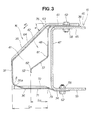
- the safety plate 16 has a generally U-shaped cross section as seen in side view of the vehicle 11 (such as shown in Fig. 3 ) and includes a top plate 35 inclined obliquely downward toward a forward direction of the vehicle 11, a bottom plate 36 opposed to the top plate 35, and a load input plate 37 connecting the top plate 35 and the bottom plate 36.
- An open end 38 of the safety plate 16, which is opposite to the load input plate 37, is fitted with the bumper beam 15 so that a hollow section 41 is defined jointly between the bumper beam 15 and the top, bottom and load-input plates 35, 36, 37 of the safety plate 16.
- An inner plate (inner impact-absorbing plate) 42 is disposed in the hollow section 41.
- the top plate 35 is inclined obliquely downward from the bumper beam 15 toward the forward direction of the vehicle 11 (in the direction of arrow al).
- the load input plate 37 continues from the top plate 35 and extends downward in a substantially vertical direction.
- the bottom plate 36 is formed to extend substantially horizontally from the load input plate 37 to the bumper beam 15.
- the inner plate 42 projects from the bumper beam 15 in such a manner that the inner plate 42 is substantially parallel with the top plate 35 and spaced from the top plate 35 by a predetermined distance ( Fig. 3 ).
- the inner plate 42 is bent into a staircase shape as seen in side view of the vehicle 11 (such as shown in Fig. 3 ) and includes a mounted section (top fastened section) 46 mounted to a top wall 45 of the bumper beam 15, a leg section 48 continuing from the mounted section 46 and extending downward along a front wall 47 of the bumper beam 15, a back support section 51 continuing from the leg section 48, being approximately parallel to the top plate 35 and spaced from the top plate 35 by a predetermined distance, and a load input flange 52 continuing from the back support section 51 and extending along the load input plate 37.
- a mounted section (top fastened section) 46 mounted to a top wall 45 of the bumper beam
- a leg section 48 continuing from the mounted section 46 and extending downward along a front wall 47 of the bumper beam
- a back support section 51 continuing from the leg section 48, being approximately parallel to the top plate 35 and spaced from the top plate 35 by a predetermined distance
- a load input flange 52 continuing from the back support section 51 and extending along the
- the bumper beam 15 includes the top wall 45 disposed substantially horizontally, the front wall 47 extending downwardly from a front end of the top wall 45, and a bottom wall 55 continuous with a lower end of the front wall 47 and disposed opposite to and in parallel with the top wall 45.
- the top wall 45 has a plurality of holes 57 ( Fig. 4 ) formed to allow the safety plate 16 and the inner plate 42 to be fastened to the top wall 45, and a plurality of nuts 58 attached by welding to an inner surface of the top wall 45 in concentric relation to respective ones of the holes 57.
- the bottom wall 55 has a plurality of holes (not shown) formed to allow the safety plate 16 to be fastened to the bottom wall 55, and a plurality of nuts 58 attached by welding to an inner surface of the bottom wall 55 in concentric relation to respective ones of the holes.
- the safety plate 16 has a maximum stroke length (or amount of deformation or yielding) Sn and hence can be deformed up to a maximum distance Sn according to the intensity of an impact force applied thereto. As the safety plate 16 undergoes deformation, the impact force applied to the safety plate 16 is reduced to a desired value (allowable maximum impact value Gm shown in Fig. 6(c) ) mainly by the inclined top plate 35, bottom plate 36 and inner plate 42).
- the safety plate 16 has an overall length Ls and a midpoint of the overall length Ls is coincident with a widthwise center of the vehicle body.
- the top plate 35 has a top mounted section 61 placed over the top wall 45 of the bumper beam 15 and fastened to the top wall 45 by a plurality of bolts 62.
- the mounted section 46 of the inner plate 42 is disposed between the top mounted section 61 of the top plate 35 and the top wall 45 of the bumper beam 15.
- a front end extremity (top bent portion) 63 of the top mounted section 61 projects from the bumper beam 15 in the forward direction of the vehicle 11.
- the top mounted section 61 is substantially horizontal and the front end extremity (top bent portion) 63 of the top mounted section 61 is contiguous with a body 64 of the top plate 35.
- the top plate body 64 is bent at an acute angle (angle ⁇ ) to the horizontal.
- the top plate body 64 has a plurality of beaded sections 65 formed to dent toward the hollow section 41 in a like manner as grooves. As seen in plan view of the vehicle 11, the beaded sections 65 extend parallel to an input direction of the impact or load (from the front to the rear of the vehicle) and they are spaced at a predetermined pitch in the vehicle width direction.
- Some of the beaded sections 65 formed on the top plate body 64 are connected continuously with recessed portions 66 formed on the top mounted section 61, and fastening holes 67 are formed in bottom walls of some of the recessed portions 66.
- the fastening holes 67 are aligned with corresponding ones of the holes 57 formed in the top wall 45 of the bumper beam 15.
- the load input plate 37 is spaced a desired distance Sn from the front wall 47 of the bumper beam 15 in the forward direction of the vehicle 11.
- the bottom plate 36 continues from a lower end of the load input plate 37.
- the bottom plate 36 includes a bottom plate body 71 provided to lie in a plane above a bottom surface of the bottom wall 55 of the bumper beam 15.
- the bottom plate 36 has a front portion 36a inclined obliquely upward at an angle ⁇ relative to the horizontal.
- the inclination angle ⁇ of the front portion 36a of the bottom plate 36 is designed to be smaller than the inclination angle ⁇ of the top plate 35 of the safety plate 16.
- the bottom plate body 71 is provided with a plurality of beaded sections 72 formed substantially in the same manner as the beaded sections 65 formed on the top plate 35.
- the bottom plate body 71 has a rear end extremity (bent portion) 73 bent downward so that a bottom mounted section 74 of the bottom plate 36 is lowered in position to a level of the bottom surface of the bottom wall 55 of the bumper beam 15.
- the inner plate 42 is disposed centrally in the hollow section 41 defined partly by the safety plate 16.
- the inner plate 42 has a length equal to the overall length (length in the vehicle width direction) Ls of the safety plate 16.
- the inner plate 42 has a maximum stroke (or amount of deformation) Sp and can be deformed up to a maximum distance SP according to the intensity of an impact force applied thereto.
- the inner plate 42 is fixed to the top wall 45 of the bumper beam 15 with its mounted section (top fastened section) 46 being forced against the top wall 45 by the top mounted section 61 of the safety plate 16. Thus, the inner plate 42 is fastened together with the safety plate 16 to the bumper beam 15.
- the mounted section 46 has a front end extremity (top bent portion) 76 bent downward and projecting in the forward direction of the vehicle 11 from the bumper beam 15.
- the leg section 48 is continuous with the top bent portion 76, extends perpendicularly to the mounted section 46, and is spaced from the bumper beam 15.
- the leg section 48 of the inner plate 42 is separated forwardly from the front wall 47 of the bumper beam 15.
- the leg section 48 may alternatively be in contact with the front wall 47 of the bumper beam 15.
- the leg section 47 extends downwardly and terminates at a lower end extremity (central bent portion) 81 which is located at a vertical central portion of the front wall 47 of the bumper beam 15. In other words, the leg section 47 is approximately half the height of a height of the front wall 47 of the bumper beam 15.
- the lower end extremity (central bent portion) 81 is continuous with the back support section 51.
- the back support section 51 is inclined obliquely downward toward the forward direction of the vehicle so that it can produce a downward depressing component force when subjected to a head-on collision.
- the back support section 51 has a front end 82 contiguous with the load input flange 52.
- the load input flange 52 is disposed at a central portion of the hollow section 41 of the safety plate 16. In other words, the load input flange 52 is located on a horizontal line extending through a vertical central portion of the load input plate 37 of the safety plate 16.
- the back support section 51 when the back support section 51 begins to deform in a downward direction (or when the safety plate 16 has achieved its deformation stroke up to about 60%) under the effect of an impact acting on the front of the vehicle 11, the back support section 51, as seen in side view of the vehicle 11, divides the hollow section 85 into an upper hollow section 84 and a lower hollow section 85 in such a manner that an area At of the upper hollow section 84 is equal to an area of the lower hollow section 85.
- the back support section 51 and the leg section 48 may be provided with beaded sections at their central portions thereof in the same manner as the beaded sections 65 that are provided on the top plate 35 of the safety plate 16.
- the load input flange 52 is bent in a vertical downward direction from the front end 82 of the back support section 51 and has a desired height.
- the safety plate 16 and the inner plate 42 undergo deformation (or stroking) in the rearward direction of the vehicle to thereby absorb the impact (see Fig. 6(b) ).
- the bumper structure requires a stroke length Sn for absorbing the impact and can provide a noticeable reduction in the stroke length.
- the inner plate 42 continues to undergo deformation (until the stroke length Sn is achieved) to thereby continuously absorb the impact.
- the inner plate 42 acts to resist the impact in cooperation with a reaction force of the safety plate 16 and reduces the impact in such a manner that the impact does not exceed a maximum allowable value Gm and varies along the maximum allowable value Gm.
- the bumper structure of the present invention is able to reduce the impact-absorbing stroke length.
- the vehicle body front part structure according to Comparative Example 1 needs to have a stroke length Su in order to reduce the applied impact to the maximum allowable impact value Gm.
- the stroke length Su is relatively long.
- the vehicle body front part structure according to Comparative Example 2 has a stroke length Sn which is shorter than the stroke length Su of Comparative Example 1, however, it involves generation of a large impact value Go which is greater than the allowable maximum impact value Gm. Due to a sudden drop in the impact absorbing capacity occurring when the stroke length reaches a value Sd, the relatively short stroke length Sn is not sufficiently long enough to reduce the impact to the allowable maximum impact value Gm.
- the vehicle body front part structure according to the embodiment of the present invention can lower the impact to a level below the allowable maximum impact value Gm even though the stroke length Sn is smaller than the stroke length Su. This is because when the stroke length reaches around a value Sd, the area At of the upper hollow section 84 and the area Ab of the lower hollow section 85 become almost equal to each other, and this is particularly effective to stabilize a form of deformation. Furthermore, by virtue of the inner plate 42, it is possible to prevent a sudden drop in the impact absorbing capacity which would otherwise occur at around the stroke length value Sd and also to shorten the stroke length.
- the bumper structure according to the embodiment of the invention is able to improve impact absorbing performance of the safety plate 16 and also to shorten the impact absorbing stroke length of the safety plate 16.
- the front bumper 21 can possess improved impact absorbing capability and reduced impact absorbing stroke length.
- the inner plate 42 may be provided on its back support section 51 and leg section 48 with beaded sections similar to the beaded sections 65, in order to produce an enhanced reaction force and shorten the stroke length.
- the load input flange 52 which is bent to extend in a vertical downward direction from the front end 82 of the back support section 51, has a predetermined height and, hence, the load input flange 52 is able to make a face-to-face contact with the load input plate 37 of the safety plate 16 and thus minimize variation in input load.
- the load input flange 52 also serves to prevent the inclined back up section 51 of the inner plate 42 from deflecting in a longitudinal direction (vehicle width direction) of the inner plate 42.
- the inner plate 42 is fixed in position in such a way that the mounted section (top fastened section) 46 is being forced against the top wall 45 of the bumper beam 15 by the top mounted section 61 of the safety plate 16. As a result, merely by securing the safety plate 16 to the top wall 45 by using the bolt 62, mounting of the inner plate 42 is automatically completed. This arrangement is able to reduce the number of parts used and simplify a mounting structure of the inner plate 42.
- the bumper structure of the present invention is used in a front body.
- the bumper structure can also be employed in a rear body.
- the bumper structure is used in a vehicle, however, it can be used in an equipment other than vehicle.
- the vehicle body front part structure according to the present invention can be suitably used in a vehicle.
Abstract
Description
- The present invention relates to bumper structure for absorbing an impact at, for example, a head-on collision of a vehicle.
- Bumper structures configured to absorb an impact via internal deformation of a bumper at a collision of a vehicle with an obstacle are known. The known bumper structures include a bumper face, a safety plate covered by the bumper face, and a bumper beam supporting the safety plate and extending in a vehicle width direction that are arranged in the named order as seen from the front of the vehicle. The safety plate has a generally U-shaped cross section and is mounted to the bumper beam while assuming a horizontal U-shaped position with its open end fitted with the bumper beam. The safety plate has a deformation guiding part provided at a lower part thereof attached to a bottom side of the bumper beam so that the safety plate is allowed to start deforming at the deformation guiding part and undergo complete collapsing to thereby absorb the impact (for example, see Patent Literature 1). Another known safety plate includes top and bottom walls having bent portions bent upward so that the safety plate is allowed to undergo deformation or collapsing at the bent portions as it absorbs an impact (for example, see Patent Literature 2).
- The safety plates shown in
Patent Literatures - Patent Literature:
- Patent Literature 1: Japanese Patent No.
4350584 - Patent Literature 2: Japanese Patent Application Laid-open Publication No.
2009-179136 - An object of the present invention is to provide a vehicle body front part structure which is capable of securing a sufficient impact-absorbing capacity and can reduce an impact-absorbing stroke length of a safety plate and a resulting impact-absorbing stroke length of a front bumper.
- According to a first aspect of the present invention, there is provided a bumper structure for a vehicle, comprising: a bumper beam extending in a width direction of the vehicle; a bumper face covering the bumper beam; and a safety plate disposed behind the bumper face and supported by the bumper beam, wherein the safety plate has a substantially U-shaped cross section and is formed of a top plate, a bottom plate disposed below the top plate, and a load input plate connecting the top plate and the bottom plate, the safety plate being joined with the bumper beam at an open end opposite to the load input plate, wherein the bumper beam and the safety plate define therebetween a hollow section, and an inner plate is disposed in the hollow section, wherein the top plate is inclined obliquely downward from the bumper beam toward a forward direction of the vehicle, the load input plate is continuous with and extending substantially vertically downward from the top plate, and the bottom plate extends substantially horizontally from the load input plate to the bumper beam, and wherein the inner plate projects from the bumper beam in substantially parallel with the top plate.
- Preferably, the inner plate is bent in a staircase shape as seen in side view of the vehicle and includes a mounted section mounted to a top wall of the bumper beam, a leg section continuing from the mounted section and extending downward along a front wall of the bumper beam, a back support section continuing from the leg section and being approximately parallel to the top plate, and a load input flange continuing from the back support section and extending along the load input plate.
- Preferably, the bottom plate has a front portion inclined obliquely upward.
- Preferably, the bottom plate has a front portion inclined obliquely upward at an angle of inclination smaller than an angle of inclination of the top plate
- Preferably, the load input flange is located on a horizontal line passing through a vertical central portion of the load input plate.
- Preferably, the inner plate has a same length in a width direction of the vehicle as the safety plate.
- Preferably, the leg section of the inner plate is separated from the front wall of the bumper beam.
- Preferably, the safety plate and the inner plate are jointly fastened to the bumper beam.
- Preferably, the inner plate has beads which are the same as beads formed on the safety plate.
- The inner plate prevents continued deformation of the safety plate when the safety plate undergoes deformation due to an impact force acting on the safety plate.
- According to the invention, the safety plate has the top plate and the bottom plate connected by the load input plate and is joined with the bumper beam at its open end so that the bumper beam and the safety plate defines a hollow section in which the inner plate is disposed. The top plate is inclined obliquely downward from the bumper beam toward a forward direction of the vehicle, the load input plate continues from the top plate and extends downward in a substantially vertical direction, and the bottom plate extends substantially horizontally from the load input plate to the bumper beam. The inner plate projects from the bumper beam in substantially parallel with the top plate. With this arrangement, when the vehicle collides with an obstacle and an impact (load) is applied to the load input plate of the safety plate, the safety plate begins to absorb the impact. The safety plate undergoes deformation or collapsing and when the degree of collapsing reaches a half of the collapsing length or stroke length, the inner plate disposed in the hollow section starts to undergo compressive deformation (stroking) concurrently with continued compressive deformation (or stroking) of the safety plate, thereby absorbing the impact. As a result, the impact-absorbing stroke length of the safety plate can be reduced and eventually the impact-absorbing stroke length of the bumper beam can be reduced.
- Furthermore, the inner plate includes the mounted section mounted to the top wall of the bumper beam, the leg section continuing from the mounted section and extending downward along the front wall of the bumper beam, the back support section continuing from the leg section and being approximately parallel to the top plate, and the load input flange continuing from the back support section and extending along the load input plate. With this arrangement, when the degree of deformation or collapsing of the safety plate reaches approximately a half of the full stroke length of the safety plate, the impact is transmitted from the load input plate of the safety plate to the load input flange of the inner plate. Upon application of the impact onto the load input flange, the back support section begins to deform together with the top and bottom plates of the safety plate, and the inner plate thus starts absorbing the impact.
- During the course deformation or collapsing, the stroke length of the inner plate reaches about 30% of the full stroke length, whereupon as seen in side view of the vehicle, the back support section of the inner plate divides the hollow section into an upper hollow section and a lower hollow section in such a manner that an area of the upper hollow section is substantially equal to an area of the lower hollow section. Consequently, as a second half of the full stroke length is achieved, the impact can be absorbed in such a manner that the impact does not exceed a desired maximum value and varies substantially along the maximum value.
-
-
Fig. 1 is a perspective view of a vehicle body front part in which a bumper structure according to an embodiment of the present invention is employed; -
Fig. 2 is a cross-sectional view taken along the line 2-2 ofFig. 1 ; -
Fig. 3 is an enlarged view of a part surrounded by acircular arc 3 ofFig. 2 ; -
Fig. 4 is an exploded perspective view of the bumper structure shown inFig. 1 ; -
Fig. 5 is a view illustrative of the manner in which the bumper structure absorbs an impact; and -
Fig. 6 is a diagrammatical view illustrative of the manner in which a safety plate undergoes deformation when the bumper structure absorbs the impact. - A preferred embodiment of the present invention will be described below with reference to the accompanying sheets of drawings.
- A vehicle body front part structure (bumper structure) according to the embodiment is employed as an obstacle countermeasure in a front part (front body) 13 of a
body 12 of avehicle 11, as shown inFig. 1 . - In the illustrated embodiment, the bumper structure is a
front bumper 21 for absorbing an impact produced when thevehicle 11 encounters a head-on collision. - As shown in
Figs. 1 and2 , the bumper structure includes a bumper beam (front bumper beam) 15 at a front side of thevehicle 11, an impact-absorbingsafety plate 16 attached to thebumper beam 15, and abumper face 17 covering thesafety plate 16. Thebumper face 16 forms a part of a front design of thevehicle 11. - The
vehicle 11 is provided with thefront bumper 21, acooling device 23 for cooling an engine, and abattery 24. Thecooling device 23 includes aheat exchanger 25 disposed behind thefront bumper 21. Theheat exchanger 25 is fixed to thefront body 13 via asupport frame 26. - The
front body 13 includes a pair of sidefront side frames vehicle body 12 and extending in a front-rear or longitudinal direction of thevehicle body 12, and the bumper beam (front bumper beam) 15 mounted tofront ends 33, 34 of thefront side frames bumper beam 15. - The bumper structure will be described in further details with reference to
Figs. 1 to 4 . - The bumper structure generally comprises the
bumper beam 15 extending in the vehicle width direction, thebumper face 17 covering thebumper beam 15, and thesafety plate 16 disposed behind thebumper face 17 and supported by thebumper beam 15. Thesafety plate 16 absorbs impact energy as it undergoes deformation or yielding. - The
safety plate 16 has a generally U-shaped cross section as seen in side view of the vehicle 11 (such as shown inFig. 3 ) and includes atop plate 35 inclined obliquely downward toward a forward direction of thevehicle 11, abottom plate 36 opposed to thetop plate 35, and aload input plate 37 connecting thetop plate 35 and thebottom plate 36. Anopen end 38 of thesafety plate 16, which is opposite to theload input plate 37, is fitted with thebumper beam 15 so that ahollow section 41 is defined jointly between thebumper beam 15 and the top, bottom and load-input plates safety plate 16. An inner plate (inner impact-absorbing plate) 42 is disposed in thehollow section 41. - The
top plate 35 is inclined obliquely downward from thebumper beam 15 toward the forward direction of the vehicle 11 (in the direction of arrow al). Theload input plate 37 continues from thetop plate 35 and extends downward in a substantially vertical direction. Thebottom plate 36 is formed to extend substantially horizontally from theload input plate 37 to thebumper beam 15. Theinner plate 42 projects from thebumper beam 15 in such a manner that theinner plate 42 is substantially parallel with thetop plate 35 and spaced from thetop plate 35 by a predetermined distance (Fig. 3 ). - The
inner plate 42 is bent into a staircase shape as seen in side view of the vehicle 11 (such as shown inFig. 3 ) and includes a mounted section (top fastened section) 46 mounted to atop wall 45 of thebumper beam 15, aleg section 48 continuing from the mountedsection 46 and extending downward along afront wall 47 of thebumper beam 15, aback support section 51 continuing from theleg section 48, being approximately parallel to thetop plate 35 and spaced from thetop plate 35 by a predetermined distance, and aload input flange 52 continuing from theback support section 51 and extending along theload input plate 37. - The
bumper beam 15 includes thetop wall 45 disposed substantially horizontally, thefront wall 47 extending downwardly from a front end of thetop wall 45, and abottom wall 55 continuous with a lower end of thefront wall 47 and disposed opposite to and in parallel with thetop wall 45. - The
top wall 45 has a plurality of holes 57 (Fig. 4 ) formed to allow thesafety plate 16 and theinner plate 42 to be fastened to thetop wall 45, and a plurality ofnuts 58 attached by welding to an inner surface of thetop wall 45 in concentric relation to respective ones of theholes 57. Thebottom wall 55 has a plurality of holes (not shown) formed to allow thesafety plate 16 to be fastened to thebottom wall 55, and a plurality ofnuts 58 attached by welding to an inner surface of thebottom wall 55 in concentric relation to respective ones of the holes. - Next, the
safety plate 16 will be described in further details. Thesafety plate 16 has a maximum stroke length (or amount of deformation or yielding) Sn and hence can be deformed up to a maximum distance Sn according to the intensity of an impact force applied thereto. As thesafety plate 16 undergoes deformation, the impact force applied to thesafety plate 16 is reduced to a desired value (allowable maximum impact value Gm shown inFig. 6(c) ) mainly by the inclinedtop plate 35,bottom plate 36 and inner plate 42). Thesafety plate 16 has an overall length Ls and a midpoint of the overall length Ls is coincident with a widthwise center of the vehicle body. - The
top plate 35 has a topmounted section 61 placed over thetop wall 45 of thebumper beam 15 and fastened to thetop wall 45 by a plurality ofbolts 62. The mountedsection 46 of theinner plate 42 is disposed between the topmounted section 61 of thetop plate 35 and thetop wall 45 of thebumper beam 15. A front end extremity (top bent portion) 63 of the topmounted section 61 projects from thebumper beam 15 in the forward direction of thevehicle 11. - The top
mounted section 61 is substantially horizontal and the front end extremity (top bent portion) 63 of the topmounted section 61 is contiguous with abody 64 of thetop plate 35. Thetop plate body 64 is bent at an acute angle (angle α) to the horizontal. Thetop plate body 64 has a plurality of beadedsections 65 formed to dent toward thehollow section 41 in a like manner as grooves. As seen in plan view of thevehicle 11, thebeaded sections 65 extend parallel to an input direction of the impact or load (from the front to the rear of the vehicle) and they are spaced at a predetermined pitch in the vehicle width direction. - Some of the beaded
sections 65 formed on thetop plate body 64 are connected continuously with recessedportions 66 formed on the topmounted section 61, and fastening holes 67 are formed in bottom walls of some of the recessedportions 66. The fastening holes 67 are aligned with corresponding ones of theholes 57 formed in thetop wall 45 of thebumper beam 15. - The
load input plate 37 is spaced a desired distance Sn from thefront wall 47 of thebumper beam 15 in the forward direction of thevehicle 11. Thebottom plate 36 continues from a lower end of theload input plate 37. - The
bottom plate 36 includes abottom plate body 71 provided to lie in a plane above a bottom surface of thebottom wall 55 of thebumper beam 15. Thebottom plate 36 has afront portion 36a inclined obliquely upward at an angle β relative to the horizontal. The inclination angle β of thefront portion 36a of thebottom plate 36 is designed to be smaller than the inclination angle α of thetop plate 35 of thesafety plate 16. Thebottom plate body 71 is provided with a plurality of beadedsections 72 formed substantially in the same manner as thebeaded sections 65 formed on thetop plate 35. - The
bottom plate body 71 has a rear end extremity (bent portion) 73 bent downward so that a bottom mountedsection 74 of thebottom plate 36 is lowered in position to a level of the bottom surface of thebottom wall 55 of thebumper beam 15. With thesafety plate 16 thus arranged, theinner plate 42 is disposed centrally in thehollow section 41 defined partly by thesafety plate 16. - Next, the
inner plate 42 will be described in further details. Theinner plate 42 has a length equal to the overall length (length in the vehicle width direction) Ls of thesafety plate 16. Theinner plate 42 has a maximum stroke (or amount of deformation) Sp and can be deformed up to a maximum distance SP according to the intensity of an impact force applied thereto. - The
inner plate 42 is fixed to thetop wall 45 of thebumper beam 15 with its mounted section (top fastened section) 46 being forced against thetop wall 45 by the topmounted section 61 of thesafety plate 16. Thus, theinner plate 42 is fastened together with thesafety plate 16 to thebumper beam 15. - The mounted
section 46 has a front end extremity (top bent portion) 76 bent downward and projecting in the forward direction of thevehicle 11 from thebumper beam 15. Theleg section 48 is continuous with the topbent portion 76, extends perpendicularly to the mountedsection 46, and is spaced from thebumper beam 15. Thus, theleg section 48 of theinner plate 42 is separated forwardly from thefront wall 47 of thebumper beam 15. However, theleg section 48 may alternatively be in contact with thefront wall 47 of thebumper beam 15. - The
leg section 47 extends downwardly and terminates at a lower end extremity (central bent portion) 81 which is located at a vertical central portion of thefront wall 47 of thebumper beam 15. In other words, theleg section 47 is approximately half the height of a height of thefront wall 47 of thebumper beam 15. The lower end extremity (central bent portion) 81 is continuous with theback support section 51. - The
back support section 51 is inclined obliquely downward toward the forward direction of the vehicle so that it can produce a downward depressing component force when subjected to a head-on collision. Theback support section 51 has afront end 82 contiguous with theload input flange 52. Theload input flange 52 is disposed at a central portion of thehollow section 41 of thesafety plate 16. In other words, theload input flange 52 is located on a horizontal line extending through a vertical central portion of theload input plate 37 of thesafety plate 16. - Preferably, as shown in
Fig. 5 , when theback support section 51 begins to deform in a downward direction (or when thesafety plate 16 has achieved its deformation stroke up to about 60%) under the effect of an impact acting on the front of thevehicle 11, theback support section 51, as seen in side view of thevehicle 11, divides thehollow section 85 into an upperhollow section 84 and a lowerhollow section 85 in such a manner that an area At of the upperhollow section 84 is equal to an area of the lowerhollow section 85. - The
back support section 51 and theleg section 48 may be provided with beaded sections at their central portions thereof in the same manner as thebeaded sections 65 that are provided on thetop plate 35 of thesafety plate 16. - The
load input flange 52 is bent in a vertical downward direction from thefront end 82 of theback support section 51 and has a desired height. - Next, operation of the bumper structure will be described below with reference to
Figs. 5 and (b) ofFig. 6 . Description is first given to an operation as to how the amount of deformation or stroke length of the bumper structure can be reduced. InFigs. 5 and6 , the bumper face 17 (Fig. 2 ) is omitted. - In the bumper structure, when an impact is applied to the front bumper at the front of the
vehicle 11, thesafety plate 16 and theinner plate 42 undergo deformation (or stroking) in the rearward direction of the vehicle to thereby absorb the impact (seeFig. 6(b) ). - The bumper structure requires a stroke length Sn for absorbing the impact and can provide a noticeable reduction in the stroke length.
- When subjected to an impact, the
bumper face 17 and thesafety plate 16 begin to deform (Fig. 6 (b-2). When thesafety plate 16 has achieved a desired amount of deformation (stroke length Ss), it begins to transfer the impact to theinner plate 42. Thus, when thesafety plate 16 has undergone deformation up to the stroke length Ss, theinner plate 42 comes into contact with thesafety plate 16 and temporarily blocks continued deformation of thesafety plate 16. - Subsequently, the
inner plate 42 continues to undergo deformation (until the stroke length Sn is achieved) to thereby continuously absorb the impact. After the stroke length exceeds the value Ss, theinner plate 42 acts to resist the impact in cooperation with a reaction force of thesafety plate 16 and reduces the impact in such a manner that the impact does not exceed a maximum allowable value Gm and varies along the maximum allowable value Gm. - In a bumper structure according to Comparative Example 2, an inner plate corresponding to the
inner plate 42 is not provided and, hence, the impact cannot be absorbed until when a stroke length Sn is achieved. In the case where thebumper beam 15 has a sufficient strength and rigidity, a very high impact value Go can be observed when the impact acts on therigid bumper beam 15. The impact value Go is greatly larger than the maximum allowable value Gm. In order to absorb the impact energy while keeping an impact value below the allowable maximum value Gm, it is necessary to increase the stroke length up to a value Su, which is considerably larger than the stroke length Sn of the bumper structure of the invention. - Thus, by virtue of the
safety plate 16 and theinner plate 42, the bumper structure of the present invention is able to reduce the impact-absorbing stroke length. - Next, a vehicle body front part structure according to the embodiment of the present invention and those of Comparative Examples 1 and 2 will be described below with reference to
Fig. 6 . - (a) of
Fig. 6 illustrates in diagrammatically cross section the vehicle body front part structure of Comparative Example 1, wherein (a-1) ofFig. 6 shows the vehicle body front part structure as it is in a pre-deformation state, and (a-2) ofFig. 6 shows the vehicle body front part structure as it is in a post-deformation state. Animpact absorbing member 201 of Comparative Example 1 includes atop wall 202, abottom wall 203 and afront wall 204 and has a stroke length Su which is longer than the stroke length Sn of the vehicle body front part structure embodying the invention. The vehicle body front part structure of Comparative Example 2 is not shown inFig. 6 but is structurally the same as the vehicle body front part structure of the invention with the exception that theinner plate 42 is removed. - (b) of
Fig. 6 illustrates in diagrammatically cross section the vehicle body front part structure according to the embodiment of the present invention, wherein (b-1) ofFig. 6 shows the vehicle body front part structure as it is in a pre-deformation state, (b-2) and (b3) ofFig. 6 show the vehicle body front part structure as it is in the course of deformation, and (b4) ofFig. 6 shows the vehicle body front part structure as it is in a post-deformation state. For purposes of illustration, the stroke lengths Su and Sn shown inFigs. 6(a) and 6(b) are shown on reduced scale as compared to the stroke length Su and Sn shown inFig. 6(c) . - (c) of
Fig. 6 is a graph showing the relationship between the impact (load) and the stroke length, wherein a vertical axis represents the impact (load) and the horizontal axis represents the stroke length. InFig. 6(c) , a thin solid line represents the Comparative Example 1, a broken line represents the Comparative Example 2, and a thick solid line represents the embodiment of the present invention. - The vehicle body front part structure according to Comparative Example 1 needs to have a stroke length Su in order to reduce the applied impact to the maximum allowable impact value Gm. The stroke length Su is relatively long.
- The vehicle body front part structure according to Comparative Example 2 has a stroke length Sn which is shorter than the stroke length Su of Comparative Example 1, however, it involves generation of a large impact value Go which is greater than the allowable maximum impact value Gm. Due to a sudden drop in the impact absorbing capacity occurring when the stroke length reaches a value Sd, the relatively short stroke length Sn is not sufficiently long enough to reduce the impact to the allowable maximum impact value Gm.
- The vehicle body front part structure according to the embodiment of the present invention can lower the impact to a level below the allowable maximum impact value Gm even though the stroke length Sn is smaller than the stroke length Su. This is because when the stroke length reaches around a value Sd, the area At of the upper
hollow section 84 and the area Ab of the lowerhollow section 85 become almost equal to each other, and this is particularly effective to stabilize a form of deformation. Furthermore, by virtue of theinner plate 42, it is possible to prevent a sudden drop in the impact absorbing capacity which would otherwise occur at around the stroke length value Sd and also to shorten the stroke length. - Thus, the bumper structure according to the embodiment of the invention is able to improve impact absorbing performance of the
safety plate 16 and also to shorten the impact absorbing stroke length of thesafety plate 16. - As a result, the
front bumper 21 can possess improved impact absorbing capability and reduced impact absorbing stroke length. - The
inner plate 42 may be provided on itsback support section 51 andleg section 48 with beaded sections similar to the beadedsections 65, in order to produce an enhanced reaction force and shorten the stroke length. - The
load input flange 52, which is bent to extend in a vertical downward direction from thefront end 82 of theback support section 51, has a predetermined height and, hence, theload input flange 52 is able to make a face-to-face contact with theload input plate 37 of thesafety plate 16 and thus minimize variation in input load. Theload input flange 52 also serves to prevent the inclined back upsection 51 of theinner plate 42 from deflecting in a longitudinal direction (vehicle width direction) of theinner plate 42. - The
inner plate 42 is fixed in position in such a way that the mounted section (top fastened section) 46 is being forced against thetop wall 45 of thebumper beam 15 by the topmounted section 61 of thesafety plate 16. As a result, merely by securing thesafety plate 16 to thetop wall 45 by using thebolt 62, mounting of theinner plate 42 is automatically completed. This arrangement is able to reduce the number of parts used and simplify a mounting structure of theinner plate 42. - In the illustrated embodiment, the bumper structure of the present invention is used in a front body. However, the bumper structure can also be employed in a rear body. Furthermore, the bumper structure is used in a vehicle, however, it can be used in an equipment other than vehicle.
- The vehicle body front part structure according to the present invention can be suitably used in a vehicle.
- List of Reference Numerals:
- 11... vehicle
- 13... front part of vehicle (front body)
- 15... bumper beam
- 16... safety plate
- 17... bumper face
- 35... top plate of safety plate
- 36... bottom plate of safety plate
- 37... load input plate of safety plate
- 38... open end of safety plate
- 41... hollow section
- 42... inner plate
- 45... top wall of bumper beam
- 46... mounted section of inner plate
- 48... leg section of inner plate
- 51... buck support section of inner plate
- 52... load input flange of inner plate
Claims (10)
- A bumper structure for a vehicle, comprising:a bumper beam extending in a width direction of the vehicle;a bumper face covering the bumper beam; anda safety plate disposed behind the bumper face and supported by the bumper beam,wherein the safety plate has a substantially U-shaped cross section and is formed of a top plate, a bottom plate disposed below the top plate, and a load input plate connecting the top plate and the bottom plate, the safety plate being joined with the bumper beam at an open end opposite to the load input plate,wherein the bumper beam and the safety plate define therebetween a hollow section, and an inner plate is disposed in the hollow section,wherein the top plate is inclined obliquely downward from the bumper beam toward a forward direction of the vehicle, the load input plate is continuous with and extending substantially vertically downward from the top plate, and the bottom plate extends substantially horizontally from the load input plate to the bumper beam, andwherein the inner plate projects from the bumper beam in substantially parallel with the top plate.
- The bumper structure of claim 1, wherein the inner plate is bent in a staircase shape as seen in side view of the vehicle and includes a mounted section mounted to a top wall of the bumper beam, a leg section continuing from the mounted section and extending downward along a front wall of the bumper beam, a back support section continuing from the leg section and being approximately parallel to the top plate, and a load input flange continuing from the back support section and extending along the load input plate.
- The bumper structure of claim 1, wherein the bottom plate has a front portion inclined obliquely upward.
- The bumper structure of claim 1, wherein the bottom plate has a front portion inclined obliquely upward at an angle of inclination smaller than an angle of inclination of the top plate.
- The bumper structure of claim 2, wherein the load input flange is located on a horizontal line passing through a vertical central portion of the load input plate.
- The bumper structure of claim 1, wherein the inner plate has a same length in a width direction of the vehicle as the safety plate.
- The bumper structure of claim 2, wherein the leg section of the inner plate is separated from the front wall of the bumper beam.
- The bumper structure of claim 1, wherein the safety plate and the inner plate are jointly fastened to the bumper beam.
- The bumper structure of claim 1, wherein the inner plate has beads which are the same as beads formed on the safety plate.
- The bumper structure of claim 1, wherein the inner plate prevents continued deformation of the safety plate when the safety plate undergoes deformation due to an impact force acting on the safety plate.
Applications Claiming Priority (2)
| Application Number | Priority Date | Filing Date | Title |
|---|---|---|---|
| JP2010029053 | 2010-02-12 | ||
| PCT/JP2010/070357 WO2011099206A1 (en) | 2010-02-12 | 2010-11-16 | Bumper structure for vehicle |
Publications (2)
| Publication Number | Publication Date |
|---|---|
| EP2508395A1 true EP2508395A1 (en) | 2012-10-10 |
| EP2508395A4 EP2508395A4 (en) | 2013-03-13 |
Family
ID=44367499
Family Applications (1)
| Application Number | Title | Priority Date | Filing Date |
|---|---|---|---|
| EP10845797A Withdrawn EP2508395A4 (en) | 2010-02-12 | 2010-11-16 | Bumper structure for vehicle |
Country Status (5)
| Country | Link |
|---|---|
| US (1) | US8500178B2 (en) |
| EP (1) | EP2508395A4 (en) |
| JP (1) | JP5396489B2 (en) |
| CN (1) | CN102695631A (en) |
| WO (1) | WO2011099206A1 (en) |
Cited By (2)
| Publication number | Priority date | Publication date | Assignee | Title |
|---|---|---|---|---|
| WO2018041772A1 (en) * | 2016-08-30 | 2018-03-08 | Bayerische Motoren Werke Aktiengesellschaft | Bumper cross beam |
| FR3127179A1 (en) * | 2021-09-21 | 2023-03-24 | Psa Automobiles Sa | Reinforcement device for a bumper beam with inclined surfaces adapted to the various impact tests. |
Families Citing this family (8)
| Publication number | Priority date | Publication date | Assignee | Title |
|---|---|---|---|---|
| CN102695631A (en) * | 2010-02-12 | 2012-09-26 | 本田技研工业株式会社 | Bumper structure for vehicle |
| KR101210024B1 (en) * | 2011-06-08 | 2012-12-07 | 현대자동차주식회사 | Connecting structure of vehicle front body |
| JP6380844B2 (en) * | 2014-10-15 | 2018-08-29 | 三菱自動車工業株式会社 | Vehicle front structure |
| US9358941B1 (en) * | 2015-01-22 | 2016-06-07 | Toyota Motor Engineering & Manufacturing North America, Inc. | Bumpers including a reinforcement patch and vehicles incorporating the same |
| JP6435285B2 (en) * | 2016-04-07 | 2018-12-05 | 本田技研工業株式会社 | Bumper structure for vehicles |
| US11014611B2 (en) * | 2019-04-11 | 2021-05-25 | Hyundai Motor Company | Front body of vehicle |
| DE102019135201A1 (en) * | 2019-12-19 | 2021-06-24 | Bayerische Motoren Werke Aktiengesellschaft | Pedestrian protection device for a motor vehicle |
| JP7121090B2 (en) * | 2020-10-14 | 2022-08-17 | 本田技研工業株式会社 | buffer structure |
Citations (3)
| Publication number | Priority date | Publication date | Assignee | Title |
|---|---|---|---|---|
| US4090728A (en) * | 1976-04-10 | 1978-05-23 | Volkswagenwerk Aktiengesellschaft | Bumper arrangement |
| US4142753A (en) * | 1975-11-21 | 1979-03-06 | Daimler-Benz Aktiengesellschaft | Vehicle bumper |
| JP2007001358A (en) * | 2005-06-22 | 2007-01-11 | Honda Motor Co Ltd | Front bumper device for vehicle |
Family Cites Families (18)
| Publication number | Priority date | Publication date | Assignee | Title |
|---|---|---|---|---|
| JPH0628897B2 (en) * | 1986-06-30 | 1994-04-20 | 東燃化学株式会社 | Method for manufacturing automobile bumper |
| JPH05139224A (en) * | 1991-11-25 | 1993-06-08 | Honda Motor Co Ltd | Bumper beam and manufacture thereof |
| US6088357A (en) * | 1997-09-26 | 2000-07-11 | International Business Machines Corporation | Auxiliary transport assist processor especially for an MPEG-2 compliant decoder |
| JP4481435B2 (en) * | 2000-05-17 | 2010-06-16 | 富士重工業株式会社 | Bumper beam structure |
| JP4057846B2 (en) * | 2002-06-07 | 2008-03-05 | 株式会社アステア | Bumper structural material |
| CN1849234B (en) * | 2003-07-03 | 2011-07-27 | 沙普公司 | Bumper system incorporating thermoformed energy absorber |
| JP4052244B2 (en) * | 2003-12-24 | 2008-02-27 | トヨタ自動車株式会社 | Bumper structure for vehicles |
| JP4350584B2 (en) * | 2004-05-07 | 2009-10-21 | 本田技研工業株式会社 | Body front structure |
| JP4255909B2 (en) * | 2004-12-24 | 2009-04-22 | 本田技研工業株式会社 | Bumper beam structure |
| JP2009513439A (en) * | 2005-10-26 | 2009-04-02 | メリディアン オートモーティブ システムズ,インコーポレイテッド | Bumper system |
| JP4626552B2 (en) * | 2006-03-27 | 2011-02-09 | 株式会社デンソー | Collision detection means |
| JP4203079B2 (en) * | 2006-04-24 | 2008-12-24 | 本田技研工業株式会社 | Bumper structure for vehicles |
| JP4291841B2 (en) * | 2006-10-11 | 2009-07-08 | トヨタ自動車株式会社 | Vehicle rear structure |
| DE112008000265T5 (en) * | 2007-02-02 | 2010-01-14 | Netshape Energy Management LLC, Novi | Energy absorber with crush boxes and rear straps |
| JP4375451B2 (en) * | 2007-07-13 | 2009-12-02 | 株式会社デンソー | Vehicle collision detection device |
| JP5016507B2 (en) | 2008-01-30 | 2012-09-05 | 本田技研工業株式会社 | Vehicle front bumper device |
| JP4850862B2 (en) | 2008-04-07 | 2012-01-11 | 本田技研工業株式会社 | Body front structure |
| CN102695631A (en) * | 2010-02-12 | 2012-09-26 | 本田技研工业株式会社 | Bumper structure for vehicle |
-
2010
- 2010-11-16 CN CN2010800605733A patent/CN102695631A/en active Pending
- 2010-11-16 EP EP10845797A patent/EP2508395A4/en not_active Withdrawn
- 2010-11-16 US US13/576,997 patent/US8500178B2/en active Active
- 2010-11-16 JP JP2011553716A patent/JP5396489B2/en not_active Expired - Fee Related
- 2010-11-16 WO PCT/JP2010/070357 patent/WO2011099206A1/en active Application Filing
Patent Citations (3)
| Publication number | Priority date | Publication date | Assignee | Title |
|---|---|---|---|---|
| US4142753A (en) * | 1975-11-21 | 1979-03-06 | Daimler-Benz Aktiengesellschaft | Vehicle bumper |
| US4090728A (en) * | 1976-04-10 | 1978-05-23 | Volkswagenwerk Aktiengesellschaft | Bumper arrangement |
| JP2007001358A (en) * | 2005-06-22 | 2007-01-11 | Honda Motor Co Ltd | Front bumper device for vehicle |
Non-Patent Citations (1)
| Title |
|---|
| See also references of WO2011099206A1 * |
Cited By (3)
| Publication number | Priority date | Publication date | Assignee | Title |
|---|---|---|---|---|
| WO2018041772A1 (en) * | 2016-08-30 | 2018-03-08 | Bayerische Motoren Werke Aktiengesellschaft | Bumper cross beam |
| US10864870B2 (en) | 2016-08-30 | 2020-12-15 | Bayerische Motoren Werke Aktiengesellschaft | Bumper cross beam |
| FR3127179A1 (en) * | 2021-09-21 | 2023-03-24 | Psa Automobiles Sa | Reinforcement device for a bumper beam with inclined surfaces adapted to the various impact tests. |
Also Published As
| Publication number | Publication date |
|---|---|
| US8500178B2 (en) | 2013-08-06 |
| JPWO2011099206A1 (en) | 2013-06-13 |
| JP5396489B2 (en) | 2014-01-22 |
| EP2508395A4 (en) | 2013-03-13 |
| CN102695631A (en) | 2012-09-26 |
| WO2011099206A1 (en) | 2011-08-18 |
| US20120306221A1 (en) | 2012-12-06 |
Similar Documents
| Publication | Publication Date | Title |
|---|---|---|
| US8500178B2 (en) | Bumper structure for vehicle | |
| US8348033B2 (en) | Impact-absorbing member | |
| US7992926B2 (en) | Vehicle end portion structure | |
| EP2116445B1 (en) | Rear structure of vehicle body | |
| JP5337123B2 (en) | Body front structure | |
| JP2007038839A (en) | Rear part car body structure for vehicle | |
| JP5883720B2 (en) | Car body rear structure | |
| CN102145676A (en) | Motor vehicle front structure | |
| US20140070567A1 (en) | Polygonal cross-sectional frame, and rear vehicle body structure | |
| JP2004148915A (en) | Bumper device for vehicle | |
| JP2008222097A (en) | Vehicle body structure for automobile | |
| CN102951205A (en) | Vehicle body front structure | |
| JP4479637B2 (en) | Bumper structure for vehicles | |
| EP2263919A1 (en) | Automobile front body structure | |
| JP5502600B2 (en) | Vehicle front structure | |
| JP2006347527A (en) | Bumper device and bumper stay | |
| JP2015189406A (en) | Bumper device of vehicle | |
| US9302712B2 (en) | Vehicle body front structure | |
| CN212796772U (en) | Anti-collision beam assembly and vehicle before vehicle | |
| JP6887741B2 (en) | Vehicle front structure | |
| JP2004210075A (en) | End structure of vehicle | |
| KR101057986B1 (en) | Bumper Unit for Vehicle | |
| KR20070055014A (en) | Front impact absorption means of vehicle | |
| JP2007038840A (en) | Rear part car body structure for automobile | |
| JP7362411B2 (en) | absorber |
Legal Events
| Date | Code | Title | Description |
|---|---|---|---|
| PUAI | Public reference made under article 153(3) epc to a published international application that has entered the european phase |
Free format text: ORIGINAL CODE: 0009012 |
|
| 17P | Request for examination filed |
Effective date: 20120706 |
|
| AK | Designated contracting states |
Kind code of ref document: A1 Designated state(s): AL AT BE BG CH CY CZ DE DK EE ES FI FR GB GR HR HU IE IS IT LI LT LU LV MC MK MT NL NO PL PT RO RS SE SI SK SM TR |
|
| A4 | Supplementary search report drawn up and despatched |
Effective date: 20130207 |
|
| RIC1 | Information provided on ipc code assigned before grant |
Ipc: B60R 19/18 20060101AFI20130201BHEP |
|
| 17Q | First examination report despatched |
Effective date: 20130219 |
|
| DAX | Request for extension of the european patent (deleted) | ||
| GRAP | Despatch of communication of intention to grant a patent |
Free format text: ORIGINAL CODE: EPIDOSNIGR1 |
|
| INTG | Intention to grant announced |
Effective date: 20141223 |
|
| STAA | Information on the status of an ep patent application or granted ep patent |
Free format text: STATUS: THE APPLICATION IS DEEMED TO BE WITHDRAWN |
|
| 18D | Application deemed to be withdrawn |
Effective date: 20150505 |