EP2508278A1 - Casting mold making apparatus and casting mold making method - Google Patents
Casting mold making apparatus and casting mold making method Download PDFInfo
- Publication number
- EP2508278A1 EP2508278A1 EP10834403A EP10834403A EP2508278A1 EP 2508278 A1 EP2508278 A1 EP 2508278A1 EP 10834403 A EP10834403 A EP 10834403A EP 10834403 A EP10834403 A EP 10834403A EP 2508278 A1 EP2508278 A1 EP 2508278A1
- Authority
- EP
- European Patent Office
- Prior art keywords
- frame
- pattern carrier
- pattern
- flask
- squeezing
- Prior art date
- Legal status (The legal status is an assumption and is not a legal conclusion. Google has not performed a legal analysis and makes no representation as to the accuracy of the status listed.)
- Granted
Links
Images













Classifications
-
- B—PERFORMING OPERATIONS; TRANSPORTING
- B22—CASTING; POWDER METALLURGY
- B22C—FOUNDRY MOULDING
- B22C11/00—Moulding machines characterised by the relative arrangement of the parts of same
-
- B—PERFORMING OPERATIONS; TRANSPORTING
- B22—CASTING; POWDER METALLURGY
- B22C—FOUNDRY MOULDING
- B22C11/00—Moulding machines characterised by the relative arrangement of the parts of same
- B22C11/02—Machines in which the moulds are moved during a cycle of successive operations
- B22C11/04—Machines in which the moulds are moved during a cycle of successive operations by a horizontal rotary table or carrier
-
- B—PERFORMING OPERATIONS; TRANSPORTING
- B22—CASTING; POWDER METALLURGY
- B22C—FOUNDRY MOULDING
- B22C15/00—Moulding machines characterised by the compacting mechanism; Accessories therefor
- B22C15/02—Compacting by pressing devices only
Definitions
- the present invention relates to an apparatus for molding a mold and a method for molding a mold, wherein foundry sand filled in a flask is squeezed by the apparatus and squeezed during the method.
- an apparatus and a method for molding a mold have been publicly known.
- the method has the following steps: raising a table and a model plate by extending a raising and lowering cylinder; loading a flask on the model plate and in turn loading a filling frame on the flask to stack them; loading foundry sand into the space that is defined by the flask and the filling frame; and squeezing the foundry sand filled in the space by means of many squeezing feet (for example, see Patent document 1).
- Patent document 1 has a problem in that the raising and lowering cylinder must be large, because the cylinder is subject to the squeezing power caused by the many squeezing feet. Further, the invention has another problem in that the oil-pressure components, such as an oil hydraulic pump, a hydraulic pipe, etc., must also be large when the cylinder is large, because the raising and lowering cylinder is generally an oil hydraulic cylinder.
- the present invention was made in light of the above problems.
- the purpose of the present invention is to provide an apparatus and a method that can make the cylinder for raising and lowering the table and the model plate (pattern plate), smaller, and can make the components that are required for the operation of the cylinder, etc., smaller.
- the apparatus of the first embodiment of the present invention for molding a mold comprises the following: a raising and lowering mechanism for raising and lowering, via a table, a pattern carrier located below a flask; a sand-loading mechanism for loading foundry sand into a space defined by the pattern plate and the flask that are loaded on the pattern carrier; a squeezing mechanism for squeezing from above the foundry sand loaded in the space; and a fixing and releasing mechanism for fixing and releasing the component that is subject to the squeezing power caused by the squeezing mechanism.
- the fixing and releasing mechanism can fix the component that is subject to the squeezing power to the end of the squeezing mechanism at a position above the raising and lowering mechanism.
- the method of the first embodiment of the present invention for molding a mold comprises a step for loading foundry sand into a space defined by (a) a pattern plate provided on the pattern carrier that can be raised and lowered via a table and (b) a flask located above the pattern carrier; a step for fixing a component that is subject to the squeezing power caused by the squeezing mechanism for squeezing from above the foundry sand filled in the space in a position above the raising and lowering mechanism by means of the fixing and releasing mechanism; a step for squeezing the foundry sand by means of the squeezing mechanism; and a step for releasing the fixed component.
- the apparatus of the second embodiment of the present invention for molding a mold comprises the following: a raising and lowering cylinder that is mounted on a base; a table that is connected to the raising and lowering cylinder; a pattern carrier that carries a pattern plate and is transported to and from a position above the table, wherein the pattern carrier is equipped with a surrounding frame that can be raised and lowered while the surrounding frame surrounds the circumference of the pattern plate; a flask-transporting mechanism that is disposed above the base and transports a flask to and from a position above the pattern carrier; and a sand hopper that is disposed above the flask-transporting mechanism and can be transported to and from a position above the flask-transporting mechanism.
- the apparatus further comprises a squeezing mechanism.
- the squeezing mechanism or the sand hopper can be alternatively transported to and from a position above the flask.
- the squeezing mechanism is disposed above the flask-transporting mechanism.
- the apparatus further comprises a filling frame that is disposed above the flask.
- the filling frame can be raised and lowered.
- the apparatus further comprises a positioning member that is fixed to the pattern carrier and determines the position of the pattern carrier relative to a frame member of the flask-transporting mechanism.
- the apparatus further comprises a wedge-driving mechanism that drives a wedge into the pattern carrier while the position of the pattern carrier and the position of the frame member are being maintained by the positioning member.
- the wedge-driving mechanism is attached to the frame member.
- the method of the second embodiment of the present invention for molding a mold comprises the following: a step for transporting a pattern carrier to a position above a table and transporting a flask to a position below a sand hopper and a filling frame and above the pattern carrier, wherein the pattern carrier carries a pattern plate and is equipped with a surrounding frame that can be raised and lowered while the surrounding frame surrounds the circumference of the pattern plate; a step for raising an upper surface of the surrounding frame above a parting plane of the pattern plate; and a step for raising the pattern carrier to form a molding space defined by the sand hopper, the filling frame, the flask, the surrounding frame, and the pattern plate.
- the method further comprises a step for loading foundry sand into the molding space through a sand-providing nozzle; a step for lowering the pattern carrier to a position where a gap between the sand hopper and the filling frame is ensured; a step for transporting the sand hopper from a position above the filling frame and transporting the squeezing mechanism to a position above the filling frame; and a step for allowing a positioning member fixed to the pattern carrier to determine the position of the pattern carrier and the position of a frame member of a flask-transporting mechanism by raising the pattern carrier.
- the method further comprises a step for driving a wedge into the pattern carrier while the position of the pattern carrier and the position of the frame member are maintained by the positioning member; a step for carrying out a first squeezing of the foundry sand by lowering the squeezing member of the squeezing mechanism; a step for carrying out a second squeezing of the foundry sand by lowering the surrounding frame while the squeezing member is being lowered; a step for raising the squeezing member; a step for removing the surrounding frame by raising it; a step for removing the wedge from the pattern carrier; a step for lowering the pattern carrier; and a step for transporting the filling frame from a position above the squeezing mechanism and transporting the sand hopper to a position above the filling frame.
- the apparatus of the third embodiment of the present invention for molding a mold comprises the following: a raising and lowering cylinder mounted on a base; a table connected to the cylinder; and a pattern carrier that carries a pattern plate and is equipped with a surrounding frame that can be raised and lowered while it surrounds the circumference of the pattern plate.
- the pattern carrier is transported to and from a position above the table.
- the apparatus further comprises a frame member disposed above the base; a flask-transporting mechanism that is disposed inside the frame member and transports the flask to a position above the pattern carrier; a squeezing mechanism that is disposed above the frame member; a filling frame that is disposed above the flask and can be raised and lowered; and a positioning member that is fixed to the pattern carrier and determines the position of the pattern carrier relative to the frame member.
- the apparatus further comprises a wedge-driving mechanism that is attached to the frame member and drives a wedge into the pattern carrier while the position of the pattern carrier and the position of the frame member are maintained by the positioning member; and a sand hopper that is disposed outside the base and stores foundry sand for being loaded from a position above the table into a space defined by the flask and the filling frame that are located on the pattern carrier that is transported outside the base.
- the method of the third embodiment of the present invention for molding a mold uses an apparatus comprising a first pattern carrier and a second pattern carrier. Each carrier carries a pattern plate and is equipped with a surrounding frame that can be raised and lowered while it surrounds a circumference of the pattern plate.
- the method comprises a step for transporting a flask to a position above the first pattern carrier and below a filling frame disposed above the first pattern carrier.
- the transporting step is carried out when the first pattern carrier is disposed above the table, and the second pattern carrier is disposed outside the base, and the flask and the filling frame are loaded on the second pattern carrier.
- the method further comprises a step for loading the flask and the filling frame on the first pattern carrier by raising the first pattern carrier.
- the method further comprises a step for forming a molding space by the pattern plate, the flask, the filling frame loaded on the second pattern carrier, and the sand hopper by inserting a sand-providing nozzle provided on the sand hopper into the filling frame.
- the method further comprises a step for opening a flask-transporting mechanism; a step for filling the molding space with the foundry sand through the sand-providing nozzle; a step for lowering the flask and filling frame that are loaded on the first pattern carrier together with the first pattern carrier; and a step for separating the sand hopper from the filling frame to a position where a gap between the sand hopper and the filling frame can be ensured.
- the method further comprises a step for transporting a flask and the filling frame that are loaded on the first pattern carrier to a position outside the base together with the first pattern carrier and transporting the flask and filling frame that are loaded on the second pattern carrier to a position above the table together with the second pattern carrier; and a step for allowing the positioning member fixed to the second pattern carrier to determine the position of the second pattern carrier and the position of the frame member by raising the second pattern carrier.
- the method further comprises a step for driving a wedge into the second pattern carrier while the position of the second pattern carrier and the position of the frame member are maintained; a step for causing the upper surface of the surrounding frame of the second pattern carrier to protrude above the parting plane of the pattern plate; a step for carrying out the first squeezing of the foundry sand by lowering the squeezing member of the squeezing mechanism; a step for carrying out the second squeezing of the foundry sand by lowering the squeezing member while the surrounding frame is being lowered; a step for raising the squeezing member; a step for removing the surrounding frame by raising it; a step for closing the flask-transporting mechanism; a step for removing the wedge from the second pattern carrier; and a step for lowering the second pattern carrier.
- the present invention adopts a fixing and releasing mechanism that can fix and release the pattern carrier, the table, etc., that are subject to a squeezing power such that the squeezing power can be received by the fixing and releasing mechanism in a position above the raising and lowering mechanism.
- the raising and lowering mechanism can be physically separated from the components that are subject to the squeezing power.
- the raising and lowering mechanism for raising and lowering a table, a pattern plate, etc. can be made smaller.
- the components that are required for the operation of the raising and lowering mechanism, such as the raising and lowering cylinder can also be made smaller.
- the apparatus 200 for molding a mold comprises the raising and lowering mechanism 202, the mechanism for loading foundry sand, the squeezing mechanism 225, and the fixing and releasing mechanism 221.
- the raising and lowering mechanism 202 raises and lowers the pattern carrier 210 via the table 203.
- the pattern carrier 210 is located below the flask W.
- the mechanism for loading foundry sand loads the foundry sand S into the space defined by the pattern plate 211 and the flask W of the pattern carrier 210.
- the squeezing mechanism 225 squeezes from above the foundry sand S loaded in the space.
- the fixing and releasing mechanism 221 fixes or releases the component that is subject to the squeezing power caused by the squeezing mechanism 225.
- the fixing and releasing mechanism 221 fixes the component that is subject to the squeezing power to the end 225c of the squeezing mechanism 225.
- Fig. 1(A) shows a state where the flask W has been transported to a position below the filling frame 224, and the pattern carrier 210 is located below the flask W.
- Fig. 1 (B) shows the state where the foundry sand S, which has been loaded into the space defined by the filling frame 224, the flask W, and the pattern plate 211, is being squeezed by the squeezing mechanism 225.
- the fixing and releasing mechanism 221 of the apparatus 200 shown in Fig. 1 is provided on the connecting frame 219.
- the connecting frame 219 is connected to the end 225c of the squeezing mechanism 225.
- the fixing and releasing mechanism 221 can be in the state for fixation by causing the engaging parts to protrude such that they engage the pattern carrier 210 and the pattern carrier 210 is fixed by them.
- the connecting frame 219 is connected to the end 225c via the upper frame 207.
- the fixing and releasing mechanism 221 can be in the state for release by pulling back the engaging parts such that they will not engage the pattern carrier 210.
- the fixing and releasing mechanism 221 is alternatively in the state for fixation, as in Fig. 1(B) , or in the state for release, as in Fig. 1(A) .
- the fixing and releasing mechanism 221 is a wedge-driving mechanism. It is attached to the connecting frame 219.
- the wedge-driving mechanism has the wedge 221b as the engaging part.
- the wedge 221b may be driven by causing it to be slid. It is slid horizontally.
- the wedge-driving mechanism which serves as the fixing and releasing mechanism 221, has a cylinder 221a and the guiding member 221c.
- the cylinder 221a can cause the wedge 221b to protrude horizontally, and can pull it back.
- the guiding member 221c may guide the movement of the wedge 221b. In this embodiment, as shown in Figs.
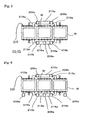
- the wedges 221b are provided in four positions such that they can be inserted into, and caused to engage with, the slots 214, while a total of four slots 214 are provided, two on each side of the pattern carrier 210.
- a plurality of liners 215 are provided on the upper surface of each slot 214. Each has a taper that corresponds to the wedges 221b.
- a plurality of (in four positions) fixing and releasing mechanisms 221 are provided in the same way as the wedge 221b.
- Fig. 2 shows the fixing and releasing mechanisms 221 corresponding to Fig. 1(A) when they are in the state for release.
- Fig. 3 shows the fixing and releasing mechanisms 221 corresponding to Fig.
- the fixing and releasing mechanisms 221 can be physically integrated, via the connecting frame 219 and upper frame 207, to the end 225c of the squeezing mechanisms 225 by being fixed to the connecting frame 219 by means of the fixing and releasing mechanisms 221, as discussed above.
- the pattern carrier 210 is fixed to the end 225c of the squeezing mechanism 225 by engaging the wedges 221b that serve as the engaging parts of the fixing and releasing mechanisms 221.
- the squeezing power caused by the squeezing mechanism 225 is loaded on the connecting frame 219 and the upper frame 207 instead of the raising and lowering mechanism 202 or base 201, etc., when the fixing and releasing mechanisms 221 are in the state for fixation.
- the raising and lowering mechanism 202 discussed above has the same functions as those of the below-discussed raising and lowering cylinders 2, 102.
- the raising and lowering mechanism 202 may be a raising and lowering cylinder, such as a hydraulic cylinder.
- the raising and lowering mechanism 202 may be provided at the center of the upper surface of the base 201.
- the table 203 is connected to the tip of the raising and lowering cylinder 202.
- the guide rods 204 are disposed outside the raising and lowering cylinder 202.
- the guide rods 204 have the same functions as those of the below-discussed guide rods 4, 104,
- the sand hopper 126 (see Fig. 24 , etc.), which can be raised and lowered and is provided outside the posts as in the below-discussed third embodiment, or the sand hopper 26 (see Fig. 12 , etc.), which is transported to and from a position above the table alternately with the squeezing mechanism (hereafter, the phrase "transported to and is transported from” will be referred to merely as “transported to and from”) as in the second embodiment, may be used as a mechanism for loading foundry sand S into the space defined by the pattern plate 211 and the flask W of the pattern carrier 210.
- the sand hopper 226 is used as in Fig. 4(B) .
- the sand hopper 226 is the same as the below-discussed sand hopper 126.
- the sand hopper 226 has the sliding gate 227, the sand-loading slot 228, the sand-providing nozzle 229, and the cylinder 231 for raising and lowering a sand hopper.
- the apparatus 200 comprises the flask-transporting conveyor 222 having the same configurations and functions as those of the below-discussed flask-transporting conveyor 122 as the flask-transporting mechanism that transports a flask to and from a position above the pattern carrier 210.
- the flask-transporting mechanism is not limited to this.
- the configurations of the flask-transporting mechanism may be the same as those of the flask-transporting conveyor 19, having the frame member 19a, having the same functions as those of the below-discussed connecting frame 219.
- the positioning members 213 are provided in the pattern carrier 210.
- the bushings 220 corresponding to the positioning members 213, are provided in the connecting frame 219.
- the configurations of the positioning members 213 and the bushings 220 shall be the same as those of the below-discussed positioning members 113 and the bushings 120 (these reference numbers are also the same).
- the fixing and releasing mechanisms 221 are fixed while the vertical positions of them are maintained by the positioning members 213 and bushings 220.
- the three posts 206a, 206b, and 206c are installed to stand on the base 201.
- the upper frame 207 is installed on the top of each post. Namely, the upper frame 207 is connected and fixed to the posts 206a, 206b, and 206c.
- the post 206a which is one of the plurality of posts 206a-206c, serves also as a main shaft of the turntable 208.
- the functions of the turntable 208 are the same as those of the below-discussed turntable 8, 108. Namely, the turntable 208 can transport the pattern carrier 210.
- the pattern carrier 210 is loaded on the turntable 208 via the support 209.
- the surrounding frame 212 is installed on the pattern carrier 210, which is loaded on the turntable 208.
- the table 203 has the cylinder 216 for raising and lowering the surrounding frame, the head 217, and the suspended rod 218, etc., as in the below-discussed table 103 (see Fig. 1 ).
- the end 225c of the squeezing mechanism 225 is fixed to the upper frame 207.
- the squeezing mechanism 225 consists of many cylinders 225a, the squeezing feet 225b, which serve as a squeezing member connected to the tip of the cylinder 225a, and the end 225c, which is a support for supporting the cylinder 225a.
- the end 225c of the squeezing mechanism 225 is fixed to the center of the lower part of the upper frame 207.
- the connecting frame 219 is connected to the three posts 206a-206c.
- the connecting frame 219 comprises a plurality of frame members 219a that are combined to form an approximate rectangle such that the connecting frame 219 surrounds the pattern carrier 210.
- the connecting frame 219 is connected to the upper frame 207 via the plurality of frame members.
- the plurality of frame members are installed at the four corners near the frame members 219a such that the plurality of frame members surround the pattern carrier 210.
- Four frame members stand near the four respective corners of the apparatus. Two of them also serve as the posts 206b and 206c.
- the other two frame members, which serve as the reinforcing frames 219b, are connected between the connecting frame 219 and the upper frame 207.
- the upper frame 207 and the connecting frame 219 are strongly connected by the plurality of frame members consisting of the frame members 219b and the posts 206b and 206c that are formed to have a frame-like shape in their horizontal planes and are perpendicularly installed such that they surround the flask W and the pattern carrier 210.
- the fixing and releasing mechanism 221 is fixed to the connecting frame 219.
- the connecting frame 219 is strongly fixed to the upper frame 207.
- the upper frame 207 is fixed to the end 225c of the squeezing mechanism 225.
- the pattern carrier 210 can be fixed to the end 225c of the squeezing mechanism 225 and the upper frame 207 by horizontally transporting the wedge 221b by means of the cylinder 221a such that the wedge 221b engages the pattern carrier 210.
- the engagement with the pattern carrier 210 can be canceled by pulling back the wedges 221b.
- the pattern carrier 210 can be transported vertically without limitation, i.e., it can be released.
- the upper frame 207 and the connecting frame 219 together form a circular frame that extends from the upper frame 207 to the pattern carrier 210.
- the pattern carrier 210 which is subject to the squeezing power provided from above by means of the squeezing mechanism 225, can be supported by the upper frame 207 and connecting frame 219, which are strongly connected to the pattern carrier 210. So, the raising and lowering mechanism 202 can be prevented from being subjected to the squeezing power.
- the post 206 below the connecting frame 219 and the base 201 can be prevented from being subjected to the squeezing power.
- the load caused by the squeezing power is several times or several tens of times larger than the load caused by the weight of the components of the apparatus on the base.
- the load caused by the squeezing power can be canceled by using the above configuration comprising the upper frame 207 and the connecting frame 219. Accordingly, needless to say, the raising and lowering mechanism 202 can be made smaller.
- the base 201 and the lower part of the post 206 can also be made smaller.
- the number of posts 206 is not limited to three, as given in Figs. 4 and 5 .
- the number may be changed depending on the size of the flask W and the configurations of the apparatus.
- the configuration that comprises three posts as shown in Figs. 4 and 5 is compatible with an apparatus where sand is loaded outside the posts as in the below-discussed third embodiment.
- two more posts like the posts 206d and 206e in Fig. 6 may be added.
- the component that can be engaged with and fixed to the fixing and releasing mechanism 221 to accept the squeezing power is not limited to the pattern carrier 210, as discussed above.
- the component may be any component as long as it can be engaged with the fixing and releasing mechanism 221 in a position above the raising and lowering mechanism 202.
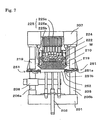
- the fixing and releasing mechanism of the apparatus of the present invention may have a configuration whereby the table 203 is fixed by having an engaging part protrude from the connecting frame 219 to be engaged with table 203 such that the table on which the squeezing power is loaded is supported by the engaging part.
- the connecting frame 219 may have a fixing and releasing mechanism 251, which has the same configurations as those of the fixing and releasing mechanisms 221, such that the wedge 251b, which serves as an engaging part, is driven by the cylinder 251a to be engaged with the slot 252 that is provided in the table 203.
- the fixing and releasing mechanism 251 in Fig. 7 can fix the table 203 by having the engaging part protrude from the connecting frame 219 to thereby be engaged with the table 203.
- the connecting frame 219 and the upper frame 207 can receive the squeezing power caused by the squeezing mechanism 225.
- the apparatus 200 comprises the fixing and releasing mechanisms 221, 251, which can alternatively fix or release the pattern carrier 210 or table 203, etc., one of which may be the component that is subject to the squeezing power. So, the component that is subject to the squeezing power can be physically separated from the raising and lowering mechanism 202 because the component can be in a position above the raising and lowering mechanism 202. Thereby the raising and lowering mechanism 202 for raising and lowering the table 203 and the pattern plate 211, such as a raising and lowering cylinder, can be made smaller.
- the apparatus 200 can be used to mold a larger mold than that can be molded by an apparatus having a configuration where the posts themselves comprise a cylinder and the upper frame itself is raised and lowered by the cylinder. So, the apparatus 200 is suitable for molding a large mold.
- the above apparatus 200 may have the same configurations as each of the configurations disclosed with respect to the apparatus 100 of the below-discussed third embodiment (see Fig. 24 , etc.). Also, each configuration of the apparatus 200 may be replaced by any of the configurations of the apparatus 40 (see Fig. 12 , etc.) given in the second embodiment.
- the fixing and releasing mechanisms 221, 251 which are both wedge-driving mechanisms that can horizontally slide and drive each of the wedges 221b, 251b, have been given as the examples of the fixing and releasing mechanism of the above apparatus 200.
- the fixing and releasing mechanism is not limited to them.
- the fixing and releasing mechanism may be the fixing and releasing mechanism 261, which is a wedge-driving mechanism that drives a wedge, which is used as an engaging part, from the connecting frame 219 by horizontally rotating (turning) it.
- the mechanism 261 in Figs. 8(A) to 8(D) has a pair of wedges 261b. Each wedge can freely rotate horizontally. Each wedge serves as an engaging part.
- the mechanism 261 has the pins 261c, each of which serves as a center for the rotation of the wedges 261b.
- the mechanism 261 has the cylinder 261a, which is connected to each end of the pair of the wedges 261b and drives the pair of the wedges 261b.
- FIGS. 8(A) and 8(B) correspond to Figs. 3(A) and 3(B) , respectively.
- Each figure is a sectional view shown when the mechanism 261 is in the state for fixation and in the state for release.
- Figs. 8(C) and 8(D) show the cross section of the mechanism 261 when it is in the state for fixation and when it is in the state for release, respectively.
- the cylinder 261a retracts, and then the wedges 261b are horizontally rotated around each of the pins 261c due to the mutual approach of the ends 261d of the pair of the wedges 261b.
- the fixing and releasing mechanism 261 engages the slots 262 in the pattern carrier 210, as in Figs. 8(A), 8(B), and 8(C) .
- the liner 262a which has a taper corresponding to a taper of the other end 261e of the wedge 261b, is provided in the upper part of each slot 262 in the pattern carrier 210.
- the fixing and releasing mechanism of the apparatus 200 may be the fixing and releasing mechanism 271.
- the fixing and releasing mechanism 271 can horizontally rotate a plate from the connecting frame 219.
- the plate serves as an engaging part.
- the plates can be horizontally rotated without limitation.
- Each serves as an engaging part.
- the mechanism 271 has the pins 271c.
- Each pin 271c serves as a center for the rotation of the plates 271b.
- the mechanism 271 has a cylinder 271a.
- Figs. 9(A) to 9(D) are figures that correspond to Figs. 8(A) to 8(D) , respectively.
- the mechanism 271 is in the state for release in Fig. 9(D) .
- the ends of the pair of the plates 271b approach each other by the retraction of the cylinder 271a, and thereby the plates 271b are horizontally rotated around each of the pins 271c.
- the fixing and releasing mechanism 271 engages the slots 272 in the pattern carrier 210, as in Figs. 9(A), 9(B), and 9(C) .
- the liner 272a is provided on the upper surface of each slot 272 in the pattern carrier 210.
- the fixing and releasing mechanism of the apparatus 200 in Fig. 9 may be configured in the same way as in Figs. 2 and 3 such that the fixing and releasing mechanism can be in the state for fixation when the plates are engaged by causing them to be horizontally slid and protrude and such that the fixing and releasing mechanism can be in the state for release when the plates are pulled back.
- the fixing and releasing mechanism may comprise one large wedge that is formed by uniting the two wedges provided at the side of the pattern carrier 210 as shown in Figs.
- the engaging part of the fixing and releasing mechanism may have approximately the same width as the lengths of both sides of the pattern carrier or the table such that the engaging part can engage both sides of the pattern carrier or the table.
- the fixing and releasing mechanism of the apparatus 200 may be, for example, the fixing and releasing mechanisms 281, 291, which vertically rotate (turn) a plate that serves as an engaging part from the connecting frame 219, as in Figs. 10 and 11 .
- the fixing and releasing mechanisms 281, 291 shown in Figs. 10 and 11 have the plates 281b, 291b and the cylinders 281a, 291b, respectively.
- the plates 281b, 291b can be vertically rotated without limitation. Each serves as an engaging part.
- the cylinders 281a, 291b each drive a plate.
- the fixing and releasing mechanisms 281, 291 are in the state for release in Figs. 10(A) and 11(A) .
- the fixing and releasing mechanism 291 in Fig. 11 has the plates 291b, 291c.
- the plates 291b, 291c serve as a pair of the engaging parts.
- the plate 291c is rotated in a direction opposite to the direction of the rotation of the plate 291b.
- the plate 291c engages the support 291d that is connected to the connecting frame 219. Thereby the plate 291c is engaged with the pattern carrier 210.
- the fixing and releasing mechanisms 261, 271, 281, 291 of the apparatus 200 may fix the table 203 and the pattern carrier 210 in a position above the raising and lowering mechanism 202. Thereby the raising and lowering mechanism 202 and the component that is subject to the squeezing power may be physically separated. As a result, the raising and lowering mechanism 202, etc., can be made smaller.
- the mechanism for providing foundry sand, etc., of the above apparatus 200 may have a cylinder, etc., which serves as a molding-space-forming mechanism for appropriately forming the molding space to have a desired shape of a pattern, such that the foundry sand in the molding space can be appropriately compressed in accordance with the desired shape.
- the method comprises the following: a step for transporting the pattern carrier 210 that carries the pattern plate 211 to a position below the sand hopper 226, which serves as a mechanism for providing foundry sand; a step for raising the pattern carrier 210 by means of the raising and lowering mechanism 202 to form a molding space defined by the sand hopper 226, the filling frame 224, the flask W, and the pattern plate 211; a step for filling the molding space with the foundry sand; a step for positioning the squeezing mechanism 225 in a position above the filling frame 224; a step for fixing the pattern carrier 210 or the table 203 that is subject to the squeezing power caused by the squeezing mechanism 225; a step for squeezing the foundry sand by means of the squeezing mechanism 225; a step for releasing the fixation of the pattern carrier
- the phrase "positioning the squeezing mechanism to a position above the filling frame” means adjusting the positional relationship between the filling frame 224 and the squeezing mechanism 225.
- the phrase means transporting the squeezing mechanism such that it will be located above the filling frame 224.
- the phrase means transporting the pattern carrier 210, the flask W, or the filling frame 224 such that it will be located below the squeezing mechanism 225.
- the phrase “fixing the pattern carrier or table that is subject to the squeezing power caused by the squeezing mechanism” means, for example, fixing the pattern carrier or table to the connecting frame 219 that is connected to the upper frame 207 such that they can receive the vertical load.
- the mechanism for fixing the pattern carrier or the table may be the above fixing and releasing mechanism 221, etc., which can release the fixed pattern carrier such that the pattern carrier can be moved vertically.
- the relative positions of the pattern carrier 210 and the connecting frame 219 are determined by means of the positioning member 213, which is fixed to the pattern carrier 210, by raising the pattern carrier 210 after the step for transporting the squeezing mechanism 225 to a position above the filling frame 224 is carried out.
- the pattern carrier 210 has the surrounding frame 212.
- the frame 212 can be raised and lowered while it surrounds the circumference of the pattern plate 211.
- the surrounding frame 212 is inserted into the molding space during the step for causing the upper surface of the surrounding frame 212 to protrude above the parting plane of the pattern plate 211.
- the step for transporting the flask is performed at least before the step for defining the molding space.
- the step for squeezing the foundry sand comprises a step for carrying out the first squeeze of the foundry sand by lowering the squeezing member (squeezing feet 225b) of the squeezing mechanism 225 and a step for carrying out the second squeeze of the foundry sand by lowering the squeezing member while the surrounding frame 212 is being lowered.
- the step for removing the flask is performed after the step for raising the squeezing member.
- the step for removing the flask is performed by raising the surrounding frame 212.
- the foundry sand is loaded through the sand-providing nozzle 229 during the step for filling the molding space with the foundry sand.
- the methods for molding a mold may have the same steps as those included in the method for molding a mold, by using the apparatus 100 in the below-discussed third embodiment. Also, the steps of the methods may be replaced by those included in the method for molding a mold by using the apparatus 40 in the second embodiment.
- the method of the present invention for molding a mold by using the apparatus 200 is characterized in that the method comprises the following: a step for loading foundry sand into the space defined by the pattern plate 211, which is loaded above the table 203 on the pattern carrier 210 that is raised and lowered by the raising and lowering mechanism 202, and defined by the flask W, which is located above the pattern carrier 211; a step for fixing the component that is subject to the squeezing power caused by the squeezing mechanism 225 for squeezing from above the foundry sand, in a position above the raising and lowering mechanism 202 by means of the fixing and releasing mechanism 221, etc.; a step for squeezing the foundry sand by means of the squeezing mechanism 225; and a step for canceling the fixation of the component that is subject to the squeezing power by means of the fixing and releasing mechanism 221, etc.
- the squeezing step can be performed while the raising and lowering mechanism and the component that is subject to the squeezing power are physically separated.
- the raising and lowering mechanism such as the raising and lowering cylinder, for raising and lowering the table and the pattern plate, can be made smaller.
- the components that are required for the operation of the raising and lowering mechanism, etc. can be made smaller.
- the apparatus 40 comprises the raising and lowering cylinder 2 (an oil hydraulic cylinder in this embodiment) and the table 3.
- the cylinder 2 is loaded at the center of the top of the base 1.
- the table 3 is connected to the tip of the raising and lowering cylinder 2.
- the apparatus 40 further comprises the guide rods 4. They are disposed outside the raising and lowering cylinder 2.
- the base 1 is equipped with the guide rods 4. They penetrate through the holders 5 such that the rods can slide vertically inside the holders 5. Incidentally, the tips of the guide rods 4 are connected to the table 3.
- the posts 6 are installed on both ends of the base 1 (see Fig. 12 ).
- the upper frame 7 is installed between the tops of the posts 6.
- the center of the turntable 8 is supported by one of the posts 6 (the post stands on the left in Fig. 12 ) at a lower position on it such that the turntable 8 can be rotated horizontally.
- the left post 6 also serves as a main shaft of the turntable 8 in Fig. 12 .
- the supports 9 (see Fig. 14 ) are attached to the turntable 8.
- the pattern carriers 10 are loaded on the supports 9 attached on both ends of the turntable 8.
- the turntable 8 can be rotated by means of an actuator (not illustrated).
- an oil hydraulic cylinder, etc. can be used as the actuator.
- the pattern carrier 10 is transported to a position above the table 3 by rotating the turntable 8 while the table 3 is in the lowest position.
- the pattern plate 11 (11A) is loaded on the pattern carrier 10.
- the pattern carrier 10 is equipped with the surrounding frame 12.
- the surrounding frame 12 can be raised and lowered while it surrounds the circumference of the pattern plate 11 (11A).
- the plurality of positioning members 13 are fixed onto both ends of the pattern carrier 10 (four positioning members are used in this embodiment).
- the positioning members can determine the position of the pattern carrier 10 relative to the frame member 19a of the below-discussed flask-transporting mechanism.
- the plurality of slots 14 for wedges are formed in the lower parts at both sides of the pattern carrier 10 (four slots are formed in this embodiment).
- the below-mentioned wedges 21b are driven into the slots.
- the liners 15 are fixed to the ceilings of the slots 14 (see Fig. 23 ). The liners 15 contact the wedges 21b.
- the table 3 is equipped with the plurality of cylinders 16 for raising and lowering a surrounding frame (the cylinders are oil hydraulic cylinders in this embodiment) (four cylinders are installed in this embodiment).
- the heads 17 are connected to the respective tips of the cylinders 16.
- the plurality of suspended rods 18 are hung on the lower surface of the surrounding frame 12 (four rods are suspended in this embodiment).
- the surrounding frame 12 can be raised and lowered via the suspended rod 18 by the extension and the retraction of the cylinder 16.
- a clamping device for clamping the pattern carrier 10 is mounted on the table 3. The clamping device is not illustrated. The clamping of the table 3 is released when the table is located in the lowest position. Also, the pattern carrier 10 is clamped to the table 3 when the table 3 is raised.
- the flask-transporting conveyor 19 is disposed above the base 1.
- the conveyor 19 serves as a mechanism for transporting the flask W to and from a position above the pattern carrier 10.
- the conveyor 19 comprises the frame member 19a and the roller 19b.
- the frame member 19a is equipped with the roller 19b.
- the frame member 19a is equipped with the plurality of bushings 20 (four bushings are used in this embodiment).
- the positioning members 13 that are fixed to the pattern carrier 10 are inserted into the bushings 20.
- the positioning members 13 are inserted in the bushings 20 when the pattern carrier 10 is raised. Thereby the position of the pattern carrier 10 is determined relative to the position of the frame member 19a.
- the lower part of the frame member 19a is equipped with the plurality of wedge-driving mechanism 21 (four mechanisms are used in this embodiment).
- the wedge-driving mechanism 21 consists of the transverse cylinder 21a, the wedge 21b connected to the tip of the transverse cylinder 21a, and the guiding member 21c for guiding the transportation of the wedge 21b.
- the wedge 21b is driven into the slot 14 by extending the transverse cylinder 21a while the position of the pattern carrier 10 relative to the position of the frame member 19a is being maintained.
- the plurality of positioning pins 22 are fixed to the upper part of the frame member 19a (four pins are used in this embodiment).
- the filling frame 23, which can be raised and lowered, is disposed above the flask W.
- the filling frame 23 is loaded on the frame member 19a.
- the frame member 19a and the filling frame 23 are positioned by means of the positioning pins 22.
- a plurality of (four cylinders in this embodiment) downward-facing cylinders 24 (each downward-facing cylinder is an oil hydraulic cylinder in this embodiment) are disposed above both ends of the filling frame 23.
- the plurality of downward-facing cylinders 24 are attached to the upper frame 7.
- the heads 25 are connected to respective tips of the plurality of the downward-facing cylinders 24, which are disposed on the left and right in Fig. 12 .
- the sand hopper 26 is disposed above the flask-transporting conveyor 19.
- the sand hopper 26 is transported to a position above the flask W and the filling frame 23.
- the sand-loading slot 28 is installed at the upper end of the sand hopper 26.
- the sand-loading slot 28 is opened and closed by the sliding gate 27.
- the sand-providing nozzle 29 is provided at the lower end of the sand hopper 26 (see Fig. 14 ).
- the rollers 30 are installed on both sides of the sand hopper 26.
- the rollers 30 can rotate on the rails 31 that are fixed to the upper frame 7.
- the squeezing mechanism 32 is disposed above the flask-transporting conveyor 19 and next to the sand hopper 26 (see Fig. 13 ).
- the squeezing mechanism 32 consists of the many cylinders 32a (they are oil hydraulic cylinders in this embodiment), the squeezing feet 32b, and the support 32c.
- the squeezing feet 32b serve as squeezing members connected to the tips of the cylinders 32a.
- the support 32c supports the cylinder 32a.
- the rollers 33 are attached to both sides of the support 32c. The rollers 33 can rotate on the rails 31.
- a transporting cylinder 34 is disposed above the squeezing mechanism 32.
- the cylinder 34 is attached to the upper frame 7 (not shown).
- the sand hopper 26 and the squeezing mechanism 32 are connected to the tip of the transporting cylinder 34 via a connecting pin 35.
- the sand hopper 26 or the squeezing mechanism 32 is alternatively transported to a position above the flask W and the filling frame 23 by the extension and the retraction of the transporting cylinder 34.
- the pattern carrier 10 which carries the pattern plate 11, is transported to a position above the table 3 by rotating the turntable 8.
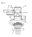
- An empty flask W is transported to a position below the sand hopper 26 and the filling frame 23 and above the pattern carriers 10 by means of the flask-transporting conveyor 19. This is the state shown in Fig. 12 and Fig. 14 .
- the upper surface of the surrounding frame 12 is caused to protrude above the parting plane of the pattern plate 11 by extending the cylinder 16 to raise and lower the surrounding frame (the upper surface is caused to protrude above the parting plane by 30 mm in this embodiment).
- the molding space is formed by the sand hopper 26, the filling frame 23, the flask W, the surrounding frame 12, and the pattern plate 11 when the pattern carrier 10, the flask W, and the filling frame 23 are raised via the table 3 by the extension of the raising and lowering cylinder 2.
- an encoder (not illustrated) is fixed to the table 3.
- the table 3 can be stopped in a desired position by means of the encoder. Thereby the size of the molding space can be adjusted.
- the lower surfaces of the heads 25 of the downward-facing cylinders 24 contact the upper surface of the filling frame 23 after the molding space is formed.
- the foundry sand S is loaded into the molding space through the sand-providing nozzle 29.
- air-discharging chambers that are not illustrated in the figures are installed on the inner surface 26a of the sand hopper 26 and on the lower inside part 26b of the sand hopper 26.
- the air-discharging chambers are connected to a switching valve.
- the switching valve is not illustrated in the figures. Air is discharged from the air-discharging chambers and goes into the sand hopper 26 when the switching valve is opened.
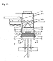
- the foundry sand S is floated and fluidized, and then the foundry sand S is loaded into the molding space through the sand-providing nozzle 29 (see Fig. 15 ).
- green sand and artificial sand that is made from ceramics, etc., can be used as the foundry sand S.
- the pattern carrier 10, the flask W, and the filling frame 23 are lowered via the table 3 by retracting the raising and lowering cylinder 2. This state is shown in Fig. 16 .
- the sand hopper 26 is transported from a position above the filling frame 23 by extending the transporting cylinder 34. Then the squeezing mechanism 32 is transported to a position above the filling frame 23. This state is shown in Fig. 17 .
- the sand-loading slot 28 is opened by operating the sliding gate 27 while the sand hopper 26 is transported from that position.
- the foundry sand S is loaded into the sand hopper 26 through the sand-loading slot 28 by a mechanism for loading foundry sand (for example, the mechanism may be a belt feeder). The mechanism is not illustrated in the figures.
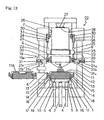
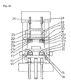
- the pattern carrier 10, the flask W, and the filling frame 23 are raised via the table 3 by extending the raising and lowering cylinder 2. Thereby the positioning members 13 are inserted into the bushings 20. As a result, the positions of the pattern carrier 10 and the frame member 19a are determined. Then the wedges 21b are driven into the slots 14 of the pattern carrier 10 by extending the traverse cylinders 21a while the positions of the pattern carrier 10 and the frame member 19a are maintained (see Figs. 18 and 22 ). Then the wedges 21b contact the liner 15.
- the first squeeze of the foundry sand S is carried out by extending many cylinders 32a to lower the squeezing feet 32b.
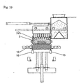
- the second squeeze of the foundry sand S is carried out by lowering the squeezing feet 32b while the surrounding frame 12 is being lowered by retracting the cylinder 16 (see Fig. 19 ).
- the squeezing feet 32b are raised by retracting the many cylinders 32a.
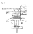
- the surrounding frame 12 is raised by extending the cylinder 16 (see Fig. 20 ).
- the upper surface of the filling frame 23 is pressed by the heads 25 of the downward-facing cylinders 24 while the surrounding frame is being removed.
- the downward-facing cylinders 24 retract along with the elevation of the surrounding frame 12 while the heads 25 of the downward-facing cylinders 24 press the upper surface of the filling frame 23. This is because the downward pressure caused by the downward-facing cylinders 24 is lower than the upward pressure caused by the cylinder 16.
- the wedges 21b are pulled from the slots 14 of the pattern carrier 10 by retracting the traverse cylinders 21a.
- the pattern carrier 10, the flask W, and the filling frame 23 are lowered via the table 3 by retracting the raising and lowering cylinder 2.
- the lower surfaces of the heads 25 of the downward-facing cylinders 24 and the upper surface of the filling frame 23 are separated along with the lowering of the filling frame 23.
- the surrounding frame 12 is lowered by retracting the cylinder 16 when the table 3 is located at the lowest position.
- the squeezing mechanism 32 is transported from a position above the filling frame 23 and the sand hopper 26 is transported to a position above the filling frame 23 by retracting the transporting cylinder 34.
- This state is shown in Fig. 21 .
- the sand-loading slot 28 is closed by reversely operating the sliding gate 27 when the sand hopper 26 is transported to that position.
- the molded flask W is transported away by means of the conveyor 19. Then another empty flask W is transported to a position below the sand hopper 26 and the filling frame 23 and above the pattern carrier 10. Then the pattern carrier 10 that carries the pattern plate 11A is transported to a position above the table 3 by rotating the turntable 8. The above operations are repeated.
- the positions of the pattern carrier 10 and the frame member 19a are determined by having the positioning members 13 be inserted into the bushings 20.
- the pattern carrier 10 is caused to be horizontal due to the determination of the positions of the pattern carrier 10 and the frame member 19a.
- the wedges 21b are driven into the slots 14 of the pattern carrier 10 while the positions of the pattern carrier 10 and the frame member 19a are maintained. Accordingly, the pattern carrier 10 is pinched, and thus fixed, by means of the frame member 19a and the wedges 21b.
- the wedges 21b are subject to the squeezing power caused by the squeezing feet 32b because the squeeze is carried out by means of the squeezing feet 32b while the pattern carrier 10 is fixed.
- the raising and lowering cylinder 2 is not subject to the squeezing power caused by the squeezing feet 32b.
- the raising and lowering cylinder 2 can be made smaller.
- the components that are required for the operation of the raising and lowering cylinder 2, etc. can be made smaller.
- the surrounding frame cannot be accurately removed if it is removed when the raising and lowering cylinder 2 is extended. This because the pattern carrier 10, etc., may shake.
- the surrounding frame is removed while the pattern carrier 10 is pinched, and thus fixed, by means of the frame member 19a and the wedges 21b. The shaking of the pattern carrier 10, etc., can be prevented. Thereby the surrounding frame can be accurately removed.
- squeezing feet 32b were used as the squeezing member in the second embodiment given above.
- the squeezing member is not limited to the squeezing feet.
- one flat squeezing board may be used as the squeezing member.
- a mechanism for raising and lowering the squeezing board may consist of a cylinder or a plurality of cylinders.
- the configurations and the modifications of the apparatus 200 of the first embodiment given above may be applied to the apparatus 40 of the second embodiment.
- the apparatus 40 of the present invention for molding a mold is characterized in that the apparatus comprises the following: a raising and lowering cylinder attached to a base; a table that is connected to the raising and lowering cylinder; a pattern carrier that carries a pattern plate and is transported to and from a position above the table, wherein the pattern carrier is equipped with a surrounding frame that can be raised and lowered while it surrounds the circumference of the pattern plate; a flask-transporting mechanism that is disposed above the base and transports a flask to and from a position above the pattern carrier; a sand hopper that is disposed above the flask-transporting mechanism and is transported to a position above the flask; a squeezing mechanism disposed above the flask-transporting mechanism, wherein the squeezing mechanism or the sand hopper is alternatively transported to and from a position above the flask; a filling frame that can be raised and lowered and is disposed above the flask; a filling frame
- the method of the present invention for molding a mold by using the apparatus 40 is characterized in that the method comprises the following: a step for transporting a pattern carrier to a position above a table, wherein the pattern carrier carries a pattern plate and is equipped with a surrounding frame that can be raised and lowered while it surrounds the circumference of the pattern plate and for transporting a flask to a position below the sand hopper and the filling frame and above the pattern carrier; a step for causing the upper surface of the surrounding frame to protrude above the parting plane of the pattern plate; a step for raising the pattern carrier to and from a molding space defined by the sand hopper, the filling frame, the flask, the surrounding frame, and the pattern plate; a step for loading foundry sand into the molding space through a sand-providing nozzle; a step for lowering the pattern carrier to a position where a gap between the sand hopper and the filling frame is ensured; a step for transporting the sand
- the raising and lowering cylinder 102 is mounted at the center of the upper part of the base 101 (the cylinder is an oil hydraulic cylinder in this embodiment).
- the table 103 is connected to the tip of the raising and lowering cylinder 102.
- the guide rods 104 are disposed outside the raising and lowering cylinder 102.
- the holders 105 are mounted on the base 101.
- the guide rods 104 can slide vertically inside the holders 105. Incidentally, the tips of the guide rods 104 are connected to the table 103.
- the posts 106 are installed on both ends of the base 101 (see Fig. 24 ).
- the upper frame 107 is installed between the tops of the posts 106.
- the center of the turntable 108 is supported by a lower part of one of the posts 106 such that the turntable 108 can be horizontally rotated (the post is located on the left in Fig. 24 ).
- the post 106 that is located on the left in Fig. 24 serves also as the main shaft of the turntable 108.
- the bearing members 109 are attached to the turntable 108 (see Fig. 25 ).
- the pattern carriers 110, 110A are loaded on both ends of the turntable 108 via the bearing members 109.
- the turntable 108 can be rotated by means of an actuator (not illustrated).
- an oil hydraulic cylinder, etc. can be used as the actuator.
- the pattern carriers 110, 110A are transported to a position above the table 3 by rotating the turntable 108 while the table 3 is in the lowest position.
- the pattern plates 111, 111A are loaded on the pattern carriers 110, 110A.
- the pattern carriers 110, 110A are equipped with the surrounding frames that can be raised and lowered while the surrounding frames each surround the circumferences of the pattern plates 111, 111A.
- the plurality of positioning members 113 (four positioning members are used in this embodiment) are fixed on both ends of both pattern carriers 110, 110A.
- the positioning members 113 determine the positions of the pattern carriers and the below-discussed frame member 119.
- the plurality of slots 114 (four wedges are used in this embodiment) are formed in both lower parts of the pattern carriers 110, 110A.
- the below-discussed wedges 121b are driven into each of the slots.
- the liners 115 are fixed to the upper inside surfaces of the slots 114.
- the liners 115 contact the wedges 121b.
- the table 103 is equipped with the plurality of cylinders 116 (the cylinders are oil hydraulic cylinders in this embodiment) for raising and lowering the surrounding frame (four cylinders are used in this embodiment).
- the rod heads 117 are each connected to the tips of the cylinders 116.
- the plurality of suspended rods 118 (four rods are used in this embodiment pieces) are hung on the lower surface of the surrounding frame 112.
- the surrounding frame 112 can be raised and lowered via the suspended rods 118 by the extension and the retraction of the cylinders 116.
- a clamping device for clamping the pattern carriers 110, 110A is mounted on the table 3. The clamping device is not illustrated in the figures. Thereby the clamping of the table 103 is released. Also, the pattern carriers 110, 110A are clamped to the table 103 when the table 103 is raised.
- the frame members 119 are disposed above the base 101.
- the plurality of bushings 120 are attached to the frame members 119 (four bushings are used in this embodiment).
- the positioning members 113 that are fixed to the pattern carriers 110, 110A are each inserted into the bushings 120.
- the positions of the pattern carriers 110, 110A and the frame members 119 are determined when the pattern carriers 110, 110A are raised to have the positioning members 113 be inserted into the bushings 120.
- the plurality of wedge-driving mechanisms 121 are attached to the lower parts of each of the frame members 119 (four wedges are used in this embodiment).
- the wedge-driving mechanism 121 consists of the traverse cylinder 121a and the guiding member 121c.
- the wedge 121b is connected to the tip of the traverse cylinder 121a.
- the guiding member 121c guides the transportation of the wedge 121b.
- the wedges 121b are each driven into the slots 114 by extending the traverse cylinders 121a while the positions of the pattern carriers 110, 110A and the frame members 119 are maintained.
- the conveyor 122 for transporting the flask W to a position above the pattern carriers 110, 110A is disposed inside the frame members 119.
- the conveyor 122 which can open and close, serves as the flask-transporting mechanism.
- the conveyor 122 consists of an arm 122a, a roller 122b, and a carrier 122c for loading the filling frame.
- the upper end of the arm 122a is rotatablely connected to the lower end of the upper frame 107.
- the roller 122b is attached to the tip (lower end) of the arm 122a.
- the carrier 122c is fixed to a position in a perpendicular part of the arm 122a.
- a plurality of positioning pins 123 are fixed to the upper part of the carrier 122c.
- the filling frame 124 is disposed above the flask W and can be raised and lowered.
- the filling frame 124 is loaded on the carrier 122c.
- the positions of the carrier 122c and the filling frame 124 are determined by the positioning pins 123.
- a plurality of downward-facing cylinders (the cylinders are four oil hydraulic cylinders in this embodiment) are disposed on both sides of the upper part of the filling frame 124.
- the downward-facing cylinders are not illustrated in the figures.
- the downward-facing cylinders are attached to the upper frame 107.
- a head is connected to each tip of the downward-facing cylinders. The head is not illustrated in the figures.
- the squeezing mechanism 125 is disposed above the frame member 119.
- the squeezing mechanism 125 consists of many cylinders 125a (the cylinders are oil hydraulic cylinders in this embodiment), squeezing feet 125b, which serve as squeezing members that are connected to the tips of the cylinders 125a, and the support 125c, which supports the cylinder 125a.
- the squeezing mechanism 125 is fixed to the center of the lower part of the upper frame 107.
- the flask W and the filling frame 124 are loaded on the pattern carrier 110A that is transported outside the base 101.
- the sand hopper 126 is disposed above the filling frame 124 that is located outside the base 101.
- the sand hopper 126 stores foundry sand S for being loaded into the molding space defined by the flask W and the filling frame 124 that are located on the pattern carrier 110A.
- the sand-loading slot 128 is provided in the upper end of the sand hopper 126.
- the sand-loading slot 128 is opened and closed by means of the sliding gate 127.
- the sand-providing nozzle 129 is provided in the lower end of the sand hopper 126.
- the sand hopper 126 can be raised and lowered through the hollow part of the moving cart 130.
- a plurality of cylinders 131 for raising and lowering the sand hopper are attached to the upper parts of the moving cart 130 outside the sand hopper 126 (four cylinders are used in this embodiment).
- the tips of the cylinders 131 are connected to the sand hopper 126.
- the sand hopper 126 can be raised and lowered by the extensions and the retractions of the cylinders 131.
- the rollers 130a are attached to the moving cart 130.
- the rollers 130a can rotate on the rail 132 that extends in the direction a flask W is moving.
- the rail 132 is supported by a post (not illustrated).
- the moving cart 130 is self-propelled by a driving mechanism (not illustrated) (for example, the driving mechanism may be a motor).
- the moving cart 130 can run by itself between a position Z1, which is right above the flask W and the filling frame 124 that have been loaded on the pattern carrier 110A outside the base 101, and a position Z2, which is a position where the sand hopper 126 is retracted (see Fig. 25 ).
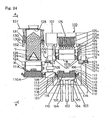
- an empty flask W is transported to a position between the pattern carrier 110 and the filling frame 124 that is disposed above the pattern carrier 110, while (a) the pattern carrier 110, which is one of the two pattern carriers 110, 110A, is disposed above the table 103 (hereafter, the pattern carrier 110 may be referred to as "a pattern carrier for a lower flask"), and (b) the pattern carrier 110A, which is the other pattern carrier (hereafter, the pattern carrier 110A may be referred to as "a pattern carrier for an upper flask”) is disposed outside the base 101, and (c) the flask W and the filling frame 124 are loaded on the pattern carrier 110A.
- This state is shown in Fig. 24 .
- the sand hopper 126 is disposed in the position Z1 when the apparatus is in the state shown in Fig. 24 .
- the flask W and the filling frame 124 are loaded on the pattern carrier 110 by raising the pattern carrier 110, the flask W, and the filling frame 124 via the table 103 by extending the raising and lowering cylinder 102. Then the positioning pins 123 are pulled off the filling frame 124. Thereby the flask-transporting conveyor 122 can be opened.
- the sand hopper 126 is lowered by retracting the cylinder 131. Thereby the sand-providing nozzle 129 is inserted into the filling frame 124. Accordingly, a molding space is formed by the pattern plate 111A, the flask W, the filling frame 124, and the sand hopper-126, which are all loaded on the pattern carrier 110A. This state is shown in Fig. 26 .
- an encoder (not illustrated) is fixed to the sand hopper 126. The sand hopper 126 can be stopped by means of the encoder in a desired position. Thereby the size of the molding space can be adjusted.
- an opening and closing mechanism (for example, the mechanism may be a cylinder) opens the flask-transporting conveyer 122. Outside the base 101, the sand-loading slot 128 is closed by reversely operating the sliding gate 127. Then the foundry sand S is loaded into the molding space through the sand-providing nozzle 129.
- air-discharging chambers (not illustrated) are installed on the inner surface 126a of the sand hopper 126 and on the lower inside part 126b of the sand hopper 126. The air-discharging chambers are connected to a switching valve. The switching valve is not illustrated in the figures.
- Air is discharged from the air-discharging chambers and goes into the sand hopper 126 when the switching valve is opened. Thereby the foundry sand S is floated and fluidized, and then the foundry sand S is loaded into the molding space through the sand-providing nozzle 129 (see Fig. 27 ).
- green sand and artificial sand that is made from ceramics, etc., can be used as the foundry sand S.
- the flask W and the filling frame 124 that are loaded on the pattern carrier 110 are lowered together with the pattern carrier 110 via the table 103 by retracting the raising and lowering cylinder 102.
- the sand hopper 126 is raised by expanding the cylinder 131.
- the sand hopper 126 is separated from the filling frame 124 to a position where a gap between the sand hopper 126 and the filling frame 124 is ensured.
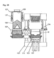
- the sand-loading slot 128 is opened by operating the sliding gate 127. This state is shown in Fig. 28 .
- the empty flask W and the filling frame 124 that are both loaded on the pattern carrier 110 are transported to a position outside the base 101 together with the pattern carrier 110.
- the flask W, which is filled with the foundry sand S, and the filling frame 124, which are loaded on the pattern carrier 110A are transported to a position above the table 103 together with the pattern carrier 110A.
- the foundry sand S is loaded into the sand hopper 126 through the sand-loading slot 128 by means of a foundry-sand-loading mechanism (for example, the mechanism may be a belt feeder) (see Fig. 29 ).
- the foundry-sand-loading mechanism is not shown in the figures.
- the pattern carrier 110A, the flask W, and the filling frame 124 are raised via the table 103 by extending the raising and lowering cylinder 102. Thereby the positioning members 113 are inserted into the bushings 120. As a result, the positions of the pattern carrier 110A and the frame member 119 are determined. Then the wedges 121b are driven into the slots 114 of the pattern carrier 110A by extending the traverse cylinders 121a while the positions of the pattern carrier 110A and the frame member 119 are maintained. Then the wedges 121b contact the liners 115.
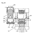
- the upper surface of the surrounding frame 112 of the pattern carrier 110A is caused to protrude above the parting plane of the pattern plate 111A by extending the cylinder 116 (the upper surface protrudes by 30 mm in this embodiment).
- This state is shown in Fig. 30 .
- the lower surfaces of the heads of the downward-facing cylinders contact the upper surface of the filling frame 124.
- the downward-facing cylinders are not illustrated.
- the squeezing feet 125b are lowered by extending many cylinders 125a to carry out the first squeeze of the foundry sand S. Then the squeezing feet 125b are lowered while the surrounding frame 112 is being lowered by retracting the cylinders 116 to carry out the secondary squeeze of the foundry sand S (see Fig. 31 ).
- the squeezing feet 125b are raised by retracting many cylinders 125a.
- the surrounding frame 112 is removed by raising it by extending the cylinder 116.
- the upper surface of the filling frame 124 is pressed by the heads of the downward-facing cylinders (not illustrated).
- the downward-facing cylinders are retracted along with the elevation of the surrounding frame 112 while their heads press the upper surface of the filling frame 124. This is because the downward pressure caused by the downward-facing cylinders is lower than the upward pressure caused by the cylinder 116.
- the flask-transporting conveyor 122 (see Fig. 32 ) is closed by the opening and closing mechanism. That mechanism is not illustrated.
- the wedges 121b are pulled from the slot 114 of the pattern carrier 110A by retracting the traverse cylinders 121a.
- the pattern carrier 110A, the flask W, and the filling frame 124 are all lowered via the table 103 by retracting the raising and lowering cylinder 102.
- the flask W is loaded on the roller 122b
- the filling frame 124 is loaded on the carrier 122c and is positioned by the positioning pins 123.
- the lower surfaces of the heads of the downward-facing cylinders and the upper surface of the filling frame 124 are separated along with the descent of the filling frame 124.
- the downward-facing cylinders are not illustrated in the figures.
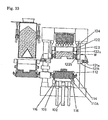
- the surrounding frame 112 is lowered by retracting the cylinders 116 when the table 103 is located in the lowest position. That state is shown in Fig. 33 .
- the molded flask W is transported away by the flask-transporting conveyor 122, and another empty flask W is transported to a position between the filling frame 124 and the pattern carriers 110A. These operations are repeated.
- the positions of the pattern carriers 110, 110A and the frame member 119 are determined by having the positioning member 113 be inserted into the bushings 120.
- the pattern carriers 110, 110A are caused to be horizontal due to the determination of the positions of the pattern carriers 110, 110A and the frame member 119.
- the wedges 121b are driven into the slot 114 of the pattern carriers 110, 110A. So, the pattern carriers 110, 110A are pinched, and thus fixed, by the frame member 119 and the wedges 121b.
- the wedges 121b are subject to the squeezing power caused by the squeezing feet 125b because the squeeze is carried out by the squeezing feet 125b while the pattern carriers 110, 110A are fixed.
- the raising and lowering cylinder 102 is not subject to the squeezing power caused by the squeezing feet 125b.
- the raising and lowering cylinder 102 can be made smaller.
- the components that are required for the operation of the raising and lowering cylinder 102, etc. can be made smaller.
- the surrounding frame cannot be accurately removed if it is removed when the raising and lowering cylinder 102 is extended. This is because a shaking of the pattern carriers 110 110A, etc., may occur.
- the surrounding frame is removed while the pattern carriers 110, 110A are pinched, and thus fixed, by means of the frame member 119a and the wedges 121b. So, the shaking of the pattern carriers 110, 110A, etc., can be prevented while the surrounding frame is being removed. Thereby the surrounding frame can be removed accurately.
- facing sand is not provided, nor is a set of operations with a chiller (densener) carried out before the foundry sand S is loaded into the molding space.
- the embodiment is not so limited. A load of facing sand or a set of operations with a chiller, etc., may be carried out, before the foundry sand S is loaded into the molding space.
- the foundry sand S is provided to the sand hopper 126 through the sand-loading slot 128 by means of a foundry-sand-loading mechanism (not illustrated).
- the moving cart 130 runs by itself by means of a driving mechanism (not illustrated) to retract the sand hopper 126 to the position Z2.
- a chiller is manually or mechanically mounted on the pattern plate (it is denoted by the number 111 in Fig. 30 ), which is loaded on the pattern carrier, which has been transported outside the base 101 (the pattern carrier is denoted by the number 110 in Fig. 30 ).
- the facing sand is manually or mechanically provided to the flask W on the pattern carrier.
- the moving cart 130 runs by itself to the position Z1 by means of the driving mechanism (not illustrated) such that the sand hopper 126 is disposed right above the flask W and the filling frame 124, which are both loaded on the pattern carrier that has been transported to a position outside the base 101.
- the sand hopper 126 is raised and lowered by the cylinder 131 outside the base 101.
- the third embodiment is not limited to such a way.
- the pattern carrier (the pattern carrier is denoted by the number 110A in Fig. 26 )
- the flask W, and the filling frame 124 which have all been transported outside the base 101
- a molding space is formed by raising the pattern carrier, the flask W, and the filling frame 124, which have all been transported to a position outside the base 101, such that the sand-providing nozzle 129 is inserted into the filling frame 124.
- a raising and lowering lifter may be installed below (right under) the pattern carrier.
- squeezing feet 125b were used as the squeezing member in the third embodiment given above.
- the squeezing member is not limited to them.
- one flat squeezing board may be used as the squeezing member.
- a mechanism for raising and lowering the squeezing board may consist of one cylinder or a plurality of cylinders.
- the configurations and the modifications of the apparatus 200 of the first embodiment given above may be applied to the apparatus 100 of the third embodiment.
- the apparatus 100 of the present invention is characterized in that it comprises the following: a raising and lowering cylinder mounted on a base; a table that is connected to the raising and lowering cylinder; a pattern carrier that carries a pattern plate and is transported to and from a position above the table, wherein the pattern carrier has a surrounding frame that can be raised and lowered while it surrounds the circumference of the pattern plate; a frame member disposed above the base; a flask-transporting mechanism that is disposed inside the frame member and transports the flask to and from a position above the pattern carrier; a squeezing mechanism disposed above the frame member; a filling frame that is disposed above the flask and can be raised and lowered; a positioning member that is fixed to the pattern carrier and can determine-the positions of the pattern carrier and the frame member; a wedge-driving mechanism that is attached to the frame member and drives a wedge into the pattern carrier while the positions of the pattern carrier and the frame member are maintained by the positioning member; and a
- the method of the present invention for molding a mold by using the apparatus 100 comprises the following: a step for transporting a flask to a position between the first pattern carrier and the filling frame that is disposed above the first pattern carrier, wherein the apparatus comprises the first and the second pattern carriers that each carry a pattern plate and are each equipped with a surrounding frame that can be raised and lowered while it surrounds the circumference of the pattern plate, (a) while the first pattern carrier is disposed above the table, and (b) while the second pattern carrier is disposed outside the base, and (c) while the second pattern carrier carries a flask and a filling frame; a step for raising the first pattern carrier to load the flask and the filling frame on the first pattern carrier; a step for inserting a sand-providing nozzle provided on the sand hopper into the filling frame to form a molding space by the pattern plate, the flask, the filling frame, and the sand hopper that are loaded on the second pattern carrier; a step for
Landscapes
- Engineering & Computer Science (AREA)
- Mechanical Engineering (AREA)
- Casting Devices For Molds (AREA)
- Road Paving Machines (AREA)
Abstract
Description
- The present invention relates to an apparatus for molding a mold and a method for molding a mold, wherein foundry sand filled in a flask is squeezed by the apparatus and squeezed during the method.
- Conventionally, an apparatus and a method for molding a mold have been publicly known. The method has the following steps: raising a table and a model plate by extending a raising and lowering cylinder; loading a flask on the model plate and in turn loading a filling frame on the flask to stack them; loading foundry sand into the space that is defined by the flask and the filling frame; and squeezing the foundry sand filled in the space by means of many squeezing feet (for example, see Patent document 1).
-
- Patent document 1: Japanese Patent Laid-open Publication No.
H6-67531 - However, the invention of
Patent document 1 has a problem in that the raising and lowering cylinder must be large, because the cylinder is subject to the squeezing power caused by the many squeezing feet. Further, the invention has another problem in that the oil-pressure components, such as an oil hydraulic pump, a hydraulic pipe, etc., must also be large when the cylinder is large, because the raising and lowering cylinder is generally an oil hydraulic cylinder. - The present invention was made in light of the above problems. The purpose of the present invention is to provide an apparatus and a method that can make the cylinder for raising and lowering the table and the model plate (pattern plate), smaller, and can make the components that are required for the operation of the cylinder, etc., smaller.
- To achieve the above purpose, the apparatus of the first embodiment of the present invention for molding a mold comprises the following: a raising and lowering mechanism for raising and lowering, via a table, a pattern carrier located below a flask; a sand-loading mechanism for loading foundry sand into a space defined by the pattern plate and the flask that are loaded on the pattern carrier; a squeezing mechanism for squeezing from above the foundry sand loaded in the space; and a fixing and releasing mechanism for fixing and releasing the component that is subject to the squeezing power caused by the squeezing mechanism. The fixing and releasing mechanism can fix the component that is subject to the squeezing power to the end of the squeezing mechanism at a position above the raising and lowering mechanism.
Also, to achieve the above purpose, the method of the first embodiment of the present invention for molding a mold comprises a step for loading foundry sand into a space defined by (a) a pattern plate provided on the pattern carrier that can be raised and lowered via a table and (b) a flask located above the pattern carrier; a step for fixing a component that is subject to the squeezing power caused by the squeezing mechanism for squeezing from above the foundry sand filled in the space in a position above the raising and lowering mechanism by means of the fixing and releasing mechanism; a step for squeezing the foundry sand by means of the squeezing mechanism; and a step for releasing the fixed component. - Also, to achieve the above purpose, the apparatus of the second embodiment of the present invention for molding a mold comprises the following: a raising and lowering cylinder that is mounted on a base; a table that is connected to the raising and lowering cylinder; a pattern carrier that carries a pattern plate and is transported to and from a position above the table, wherein the pattern carrier is equipped with a surrounding frame that can be raised and lowered while the surrounding frame surrounds the circumference of the pattern plate; a flask-transporting mechanism that is disposed above the base and transports a flask to and from a position above the pattern carrier; and a sand hopper that is disposed above the flask-transporting mechanism and can be transported to and from a position above the flask-transporting mechanism. The apparatus further comprises a squeezing mechanism. The squeezing mechanism or the sand hopper can be alternatively transported to and from a position above the flask. The squeezing mechanism is disposed above the flask-transporting mechanism. The apparatus further comprises a filling frame that is disposed above the flask. The filling frame can be raised and lowered. The apparatus further comprises a positioning member that is fixed to the pattern carrier and determines the position of the pattern carrier relative to a frame member of the flask-transporting mechanism. The apparatus further comprises a wedge-driving mechanism that drives a wedge into the pattern carrier while the position of the pattern carrier and the position of the frame member are being maintained by the positioning member. The wedge-driving mechanism is attached to the frame member.
Also, to achieve the above purpose, the method of the second embodiment of the present invention for molding a mold comprises the following: a step for transporting a pattern carrier to a position above a table and transporting a flask to a position below a sand hopper and a filling frame and above the pattern carrier, wherein the pattern carrier carries a pattern plate and is equipped with a surrounding frame that can be raised and lowered while the surrounding frame surrounds the circumference of the pattern plate; a step for raising an upper surface of the surrounding frame above a parting plane of the pattern plate; and a step for raising the pattern carrier to form a molding space defined by the sand hopper, the filling frame, the flask, the surrounding frame, and the pattern plate. The method further comprises a step for loading foundry sand into the molding space through a sand-providing nozzle; a step for lowering the pattern carrier to a position where a gap between the sand hopper and the filling frame is ensured; a step for transporting the sand hopper from a position above the filling frame and transporting the squeezing mechanism to a position above the filling frame; and a step for allowing a positioning member fixed to the pattern carrier to determine the position of the pattern carrier and the position of a frame member of a flask-transporting mechanism by raising the pattern carrier. The method further comprises a step for driving a wedge into the pattern carrier while the position of the pattern carrier and the position of the frame member are maintained by the positioning member; a step for carrying out a first squeezing of the foundry sand by lowering the squeezing member of the squeezing mechanism; a step for carrying out a second squeezing of the foundry sand by lowering the surrounding frame while the squeezing member is being lowered; a step for raising the squeezing member; a step for removing the surrounding frame by raising it; a step for removing the wedge from the pattern carrier; a step for lowering the pattern carrier; and a step for transporting the filling frame from a position above the squeezing mechanism and transporting the sand hopper to a position above the filling frame.
Also, to achieve the above purpose, the apparatus of the third embodiment of the present invention for molding a mold comprises the following: a raising and lowering cylinder mounted on a base; a table connected to the cylinder; and a pattern carrier that carries a pattern plate and is equipped with a surrounding frame that can be raised and lowered while it surrounds the circumference of the pattern plate. The pattern carrier is transported to and from a position above the table. The apparatus further comprises a frame member disposed above the base; a flask-transporting mechanism that is disposed inside the frame member and transports the flask to a position above the pattern carrier; a squeezing mechanism that is disposed above the frame member; a filling frame that is disposed above the flask and can be raised and lowered; and a positioning member that is fixed to the pattern carrier and determines the position of the pattern carrier relative to the frame member. The apparatus further comprises a wedge-driving mechanism that is attached to the frame member and drives a wedge into the pattern carrier while the position of the pattern carrier and the position of the frame member are maintained by the positioning member; and a sand hopper that is disposed outside the base and stores foundry sand for being loaded from a position above the table into a space defined by the flask and the filling frame that are located on the pattern carrier that is transported outside the base.
Also, to achieve the above purpose, the method of the third embodiment of the present invention for molding a mold uses an apparatus comprising a first pattern carrier and a second pattern carrier. Each carrier carries a pattern plate and is equipped with a surrounding frame that can be raised and lowered while it surrounds a circumference of the pattern plate. The method comprises a step for transporting a flask to a position above the first pattern carrier and below a filling frame disposed above the first pattern carrier. The transporting step is carried out when the first pattern carrier is disposed above the table, and the second pattern carrier is disposed outside the base, and the flask and the filling frame are loaded on the second pattern carrier. The method further comprises a step for loading the flask and the filling frame on the first pattern carrier by raising the first pattern carrier. The method further comprises a step for forming a molding space by the pattern plate, the flask, the filling frame loaded on the second pattern carrier, and the sand hopper by inserting a sand-providing nozzle provided on the sand hopper into the filling frame. The method further comprises a step for opening a flask-transporting mechanism; a step for filling the molding space with the foundry sand through the sand-providing nozzle; a step for lowering the flask and filling frame that are loaded on the first pattern carrier together with the first pattern carrier; and a step for separating the sand hopper from the filling frame to a position where a gap between the sand hopper and the filling frame can be ensured. The method further comprises a step for transporting a flask and the filling frame that are loaded on the first pattern carrier to a position outside the base together with the first pattern carrier and transporting the flask and filling frame that are loaded on the second pattern carrier to a position above the table together with the second pattern carrier; and a step for allowing the positioning member fixed to the second pattern carrier to determine the position of the second pattern carrier and the position of the frame member by raising the second pattern carrier. The method further comprises a step for driving a wedge into the second pattern carrier while the position of the second pattern carrier and the position of the frame member are maintained; a step for causing the upper surface of the surrounding frame of the second pattern carrier to protrude above the parting plane of the pattern plate; a step for carrying out the first squeezing of the foundry sand by lowering the squeezing member of the squeezing mechanism; a step for carrying out the second squeezing of the foundry sand by lowering the squeezing member while the surrounding frame is being lowered; a step for raising the squeezing member; a step for removing the surrounding frame by raising it; a step for closing the flask-transporting mechanism; a step for removing the wedge from the second pattern carrier; and a step for lowering the second pattern carrier. - The present invention adopts a fixing and releasing mechanism that can fix and release the pattern carrier, the table, etc., that are subject to a squeezing power such that the squeezing power can be received by the fixing and releasing mechanism in a position above the raising and lowering mechanism. Thereby the raising and lowering mechanism can be physically separated from the components that are subject to the squeezing power. As a result, the raising and lowering mechanism for raising and lowering a table, a pattern plate, etc., can be made smaller. Further, the components that are required for the operation of the raising and lowering mechanism, such as the raising and lowering cylinder, can also be made smaller.
-
- [
Fig. 1] Fig. 1 includes figures of the important parts of the molding apparatus of the first embodiment.Fig. 1(A) is a sectional view of the molding apparatus when the flask is located below the filling frame and above the pattern carrier, and when the pattern carrier is not fixed by the fixing and releasing mechanism.Fig. 1(B) is a sectional view of the molding apparatus while the foundry sand loaded in the molding space that is defined by the filling frame, the flask, and the pattern plate is being squeezed by means of the squeezing mechanism, and when the fixing and releasing mechanism is in the state for fixation. - [
Fig. 2] Fig. 2 includes figures of the first embodiment when the fixing and releasing mechanism of the molding apparatus is in the state for release.Fig. 2(A) is a sectional view of the important sections.Fig. 2(B) is a sectional view of the cross section C1-C1 inFig. 2(A) . - [
Fig. 3] Fig. 3 includes figures of the first embodiment when the fixing and releasing mechanism of the molding apparatus is in the state for fixation.Fig. 3(A) is a sectional view of the important parts.Fig. 3(B) is a sectional view of the cross section C2-C2 inFig. 3(A) . - [
Fig. 4] Fig. 4 includes figures illustrating the relationship among the upper frame, the connecting frame, and the posts of the molding apparatus in the first embodiment.Fig. 4(A) is a sectional view of the cross section C3-C3 inFig. 4(B). Fig. 4(B) is a sectional view corresponding toFig. 1(A) .Fig. 4(C) is a sectional view of the cross section C4-C4 inFig. 4(B) . - [
Fig. 5] Fig. 5 is a sectional view of the cross section C5-C5 inFig. 4(A) .Fig. 5 illustrates the relationship among the upper frame, the connecting frame, and the post of the molding apparatus in the first embodiment. - [
Fig. 6] Fig. 6 is a sectional view of a modified example of the first embodiment. A post is further adopted in the modified example.Fig. 6 corresponds toFig. 5 . - [
Fig. 7] Fig. 7 is a sectional view of a modified example of the first embodiment. In this modified example, the table is fixed by means of the fixing and releasing mechanism, and the table experiences the squeezing power.Fig. 7 corresponds toFig. 1(B) . - [
Fig. 8] Fig. 8 includes figures illustrating a modified example of the first embodiment. In this modified example, the apparatus has a fixing and releasing mechanism that is a wedge that can be engaged with the pattern carrier by being horizontally rotated.Fig. 8(A) is a sectional view of the important parts.Fig. 8(B) shows the cross section C6-C6 inFig. 8(A). Fig. 8(C) shows the cross section C7-C7 inFig. 8(A). Fig. 8(D) is a sectional view of the apparatus when it is in the state for release.Fig. 8(D) corresponds toFig. 8(C) . - [
Fig. 9] Fig. 9 is a figure illustrating the modified example of the first embodiment. In the modified example, the fixing and releasing mechanism consists of engaging plates. They can be horizontally rotated.Fig. 9(A) is a sectional view of the important parts.Fig. 9(B) shows the cross section C8-C8 inFig. 9(A). Fig. 9(C) shows the cross section C9-C9 inFig. 9(A). Fig. 9(D) shows a cross section of the fixing and releasing mechanism when it is in the state for release.Fig. 9(D) corresponds toFig. 9(C) . - [
Fig. 10] Fig. 10 is a sectional view illustrating a modified example of the first embodiment. In the modified example, the fixing and releasing mechanism consists of engaging plates that can be vertically rotated.Fig. 10(A) shows the fixing and releasing mechanism when it is in the status for release.Fig. 10(B) shows the fixing and releasing mechanism when it is in the state for fixation. - [
Fig. 11] Fig. 11 shows a sectional view illustrating the important parts of a further modified example of the example inFig. 10 in the first embodiment.Fig. 11(A) shows the fixing and releasing mechanism when it is in the state for release.Fig. 11(B) shows the fixing and releasing mechanism when it is in the state for fixation. - [
Fig. 12] Fig. 12 is a figure of the second embodiment and is a right-side view ofFig. 14 . InFig. 12 , the sand hopper has been transported to a position above the filling frame. - [
Fig. 13] Fig. 13 is a figure of the second embodiment and is a right-side view ofFig. 14 . InFig. 13 , the squeezing mechanism has been transported to a position above the filling frame. - [
Fig. 14] Fig. 14 is a partially simplified figure of the apparatus of the second embodiment when the flask is empty, and after the flask has been transported to a position below the sand hopper and the filling frame and above the pattern carrier. - [
Fig. 15] Fig. 15 is a partially simplified front view of the apparatus of the second embodiment after the molding space has been filled with foundry sand. - [
Fig. 16] Fig. 16 is a partially simplified front view of the apparatus of the second embodiment after the pattern carrier, the flask, and the filling frame have been lowered to a position where a gap between the sand hopper and the filling frame is ensured. - [
Fig. 17] Fig. 17 is a partially simplified front view of the apparatus of the second embodiment after the squeezing mechanism has been transported to a position above the filling frame. - [
Fig. 18] Fig. 18 is a partially simplified front view of the apparatus of the second embodiment after the wedges have been driven into the slots in the pattern carrier. - [
Fig. 19] Fig. 19 is a partially simplified front view of the apparatus of the second embodiment after the primary squeeze and the secondary squeeze of the foundry sand have been carried out. - [
Fig. 20] Fig. 20 is a partially simplified front view of the apparatus of the second embodiment after the surrounding frame has been removed. - [
Fig. 21] Fig. 21 is a partially simplified front view of the apparatus of the second embodiment after the sand hopper has been transported to a position above the filling frame. - [
Fig. 22] Fig. 22 is a figure of the second embodiment.Fig. 22 is a right-side view ofFig. 18 . InFig. 22 , the wedges have been driven into the slots in the pattern carrier. - [
Fig. 23] Fig. 23 is a figure of the second embodiment.Fig. 23 is a (partially simplified) figure showing the cross section A-A inFig. 13 . - [
Fig. 24] Fig. 24 is a sectional view of the apparatus of the third embodiment when the flask is empty and after the flask is transported to a position between the pattern carrier and filling frame, which are located above the table. - [
Fig. 25] Fig. 25 is a figure of the third embodiment.Fig. 25 shows the cross section A-A inFig. 24 . InFig. 25 , a flask-transporting conveyor, the filling frame, etc., are omitted. Incidentally, inFig. 25 , the sand hopper has been transported to a position outside the base. - [
Fig. 26] Fig. 26 is a sectional side view of the apparatus of the third embodiment after the flask and the filling frame have been loaded on the pattern carrier above the table, and the molding space has been formed outside the base. - [
Fig. 27] Fig. 27 is a side sectional view of the apparatus of the third embodiment after the flask-transporting conveyor has been opened above the table, and the molding space that is located outside the base has been filled with foundry sand. - [
Fig. 28] Fig. 28 is a side sectional view showing the apparatus of the third embodiment after the flask and the filling frame, which are located above the table, have been lowered together with the pattern carrier, and the sand hopper, which is located outside the base, has been separated from the filling frame such that a gap between the sand hopper and the filling frame is ensured. - [
Fig. 29] Fig. 29 is a side sectional view of the apparatus of the third embodiment after the turntable has been rotated, and foundry sand has been loaded in the sand hopper that is located outside the base. - [
Fig. 30] Fig. 30 is a side sectional view showing the apparatus of the third embodiment after the pattern carrier, the flask, and the filling frame have been raised above the table, and after the wedges have been driven into the slots of the pattern carrier, and after the upper surface of the surrounding frame has been raised above the parting plane of the pattern plate. - [
Fig. 31] Fig. 31 is a side sectional view showing the apparatus of the third embodiment after the primary squeeze and the secondary squeeze of the foundry sand have been carried out above the table. - [
Fig. 32] Fig. 32 is a figure of the apparatus of the third embodiment, above the table, after the squeezing feet have been raised, and after the surrounding frame has been removed, and after the flask-transporting conveyor has been closed. - [
Fig. 33] Fig. 33 is a side sectional view of the apparatus of the third embodiment, above the table, after the wedges have been pulled out from the slots in the pattern carrier, and after the pattern carrier, the flask, and the filling frame have been lowered, and after the surrounding frame has been lowered. - Hereafter, the apparatus and the method of the present invention for molding a mold will be explained with reference to the drawings. First, the
apparatus 200 of the present invention for molding a mold will be explained as the first embodiment with reference toFigs. 1 to 11 . - As shown in
Fig. 1 , theapparatus 200 for molding a mold comprises the raising and loweringmechanism 202, the mechanism for loading foundry sand, the squeezingmechanism 225, and the fixing and releasingmechanism 221. The raising and loweringmechanism 202 raises and lowers thepattern carrier 210 via the table 203. Thepattern carrier 210 is located below the flask W. The mechanism for loading foundry sand loads the foundry sand S into the space defined by thepattern plate 211 and the flask W of thepattern carrier 210. The squeezingmechanism 225 squeezes from above the foundry sand S loaded in the space. The fixing and releasingmechanism 221 fixes or releases the component that is subject to the squeezing power caused by the squeezingmechanism 225. In a position above the raising and loweringmechanism 202, the fixing and releasingmechanism 221 fixes the component that is subject to the squeezing power to theend 225c of the squeezingmechanism 225. Incidentally,Fig. 1(A) shows a state where the flask W has been transported to a position below the fillingframe 224, and thepattern carrier 210 is located below the flask W.Fig. 1 (B) shows the state where the foundry sand S, which has been loaded into the space defined by the fillingframe 224, the flask W, and thepattern plate 211, is being squeezed by the squeezingmechanism 225. - The fixing and releasing
mechanism 221 of theapparatus 200 shown inFig. 1 is provided on the connectingframe 219. The connectingframe 219 is connected to theend 225c of the squeezingmechanism 225. The fixing and releasingmechanism 221 can be in the state for fixation by causing the engaging parts to protrude such that they engage thepattern carrier 210 and thepattern carrier 210 is fixed by them. Incidentally, as described hereafter, the connectingframe 219 is connected to theend 225c via theupper frame 207. The fixing and releasingmechanism 221 can be in the state for release by pulling back the engaging parts such that they will not engage thepattern carrier 210. Thus, the fixing and releasingmechanism 221 is alternatively in the state for fixation, as inFig. 1(B) , or in the state for release, as inFig. 1(A) . - Specifically, the fixing and releasing
mechanism 221 is a wedge-driving mechanism. It is attached to the connectingframe 219. The wedge-driving mechanism has thewedge 221b as the engaging part. Thewedge 221b may be driven by causing it to be slid. It is slid horizontally. More specifically, the wedge-driving mechanism, which serves as the fixing and releasingmechanism 221, has acylinder 221a and the guidingmember 221c. Thecylinder 221a can cause thewedge 221b to protrude horizontally, and can pull it back. The guidingmember 221c may guide the movement of thewedge 221b. In this embodiment, as shown inFigs. 2 and 3 , thewedges 221b are provided in four positions such that they can be inserted into, and caused to engage with, theslots 214, while a total of fourslots 214 are provided, two on each side of thepattern carrier 210. A plurality ofliners 215 are provided on the upper surface of eachslot 214. Each has a taper that corresponds to thewedges 221b. Also, a plurality of (in four positions) fixing and releasingmechanisms 221 are provided in the same way as thewedge 221b.Fig. 2 shows the fixing and releasingmechanisms 221 corresponding toFig. 1(A) when they are in the state for release.Fig. 3 shows the fixing and releasingmechanisms 221 corresponding toFig. 1(B) when it is in the state for fixation. The fixing and releasingmechanisms 221 can be physically integrated, via the connectingframe 219 andupper frame 207, to theend 225c of the squeezingmechanisms 225 by being fixed to the connectingframe 219 by means of the fixing and releasingmechanisms 221, as discussed above. Thereby, in the state for fixation as inFigs. 1(B) and3 , thepattern carrier 210 is fixed to theend 225c of the squeezingmechanism 225 by engaging thewedges 221b that serve as the engaging parts of the fixing and releasingmechanisms 221. Thus, the squeezing power caused by the squeezingmechanism 225 is loaded on the connectingframe 219 and theupper frame 207 instead of the raising and loweringmechanism 202 orbase 201, etc., when the fixing and releasingmechanisms 221 are in the state for fixation. - The raising and lowering
mechanism 202 discussed above has the same functions as those of the below-discussed raising and loweringcylinders mechanism 202 may be a raising and lowering cylinder, such as a hydraulic cylinder. The raising and loweringmechanism 202 may be provided at the center of the upper surface of thebase 201. The table 203 is connected to the tip of the raising and loweringcylinder 202. Theguide rods 204 are disposed outside the raising and loweringcylinder 202. Theguide rods 204 have the same functions as those of the below-discussedguide rods - For example, the sand hopper 126 (see
Fig. 24 , etc.), which can be raised and lowered and is provided outside the posts as in the below-discussed third embodiment, or the sand hopper 26 (seeFig. 12 , etc.), which is transported to and from a position above the table alternately with the squeezing mechanism (hereafter, the phrase "transported to and is transported from" will be referred to merely as "transported to and from") as in the second embodiment, may be used as a mechanism for loading foundry sand S into the space defined by thepattern plate 211 and the flask W of thepattern carrier 210. In this embodiment, as inFig. 4(B) , thesand hopper 226 is used. Thesand hopper 226 is the same as the below-discussedsand hopper 126. In the same way as in the third embodiment, thesand hopper 226 has the slidinggate 227, the sand-loading slot 228, the sand-providingnozzle 229, and thecylinder 231 for raising and lowering a sand hopper. - For example, the
apparatus 200 comprises the flask-transportingconveyor 222 having the same configurations and functions as those of the below-discussed flask-transportingconveyor 122 as the flask-transporting mechanism that transports a flask to and from a position above thepattern carrier 210. However, the flask-transporting mechanism is not limited to this. For example, the configurations of the flask-transporting mechanism may be the same as those of the flask-transportingconveyor 19, having theframe member 19a, having the same functions as those of the below-discussed connectingframe 219. - As a mechanism for keeping the pattern carrier horizontal, the
positioning members 213 are provided in thepattern carrier 210. Thebushings 220 corresponding to thepositioning members 213, are provided in the connectingframe 219. The configurations of thepositioning members 213 and thebushings 220 shall be the same as those of the below-discussedpositioning members 113 and the bushings 120 (these reference numbers are also the same). The fixing and releasingmechanisms 221 are fixed while the vertical positions of them are maintained by thepositioning members 213 andbushings 220. - By the way, as in
Figs. 4 and5 , as a plurality of posts, the threeposts base 201. Theupper frame 207 is installed on the top of each post. Namely, theupper frame 207 is connected and fixed to theposts post 206a, which is one of the plurality ofposts 206a-206c, serves also as a main shaft of theturntable 208. The functions of theturntable 208 are the same as those of the below-discussedturntable turntable 208 can transport thepattern carrier 210. Thepattern carrier 210 is loaded on theturntable 208 via thesupport 209. As in the below-discussedpattern carrier 110, the surroundingframe 212 is installed on thepattern carrier 210, which is loaded on theturntable 208. The table 203 has thecylinder 216 for raising and lowering the surrounding frame, thehead 217, and the suspendedrod 218, etc., as in the below-discussed table 103 (seeFig. 1 ). - The
end 225c of the squeezingmechanism 225 is fixed to theupper frame 207. As in the below-discussed squeezingmechanisms mechanism 225 consists ofmany cylinders 225a, the squeezingfeet 225b, which serve as a squeezing member connected to the tip of thecylinder 225a, and theend 225c, which is a support for supporting thecylinder 225a. In this embodiment, theend 225c of the squeezingmechanism 225 is fixed to the center of the lower part of theupper frame 207. - On the other hand, the connecting
frame 219 is connected to the threeposts 206a-206c. Also, the connectingframe 219 comprises a plurality offrame members 219a that are combined to form an approximate rectangle such that the connectingframe 219 surrounds thepattern carrier 210. The connectingframe 219 is connected to theupper frame 207 via the plurality of frame members. The plurality of frame members are installed at the four corners near theframe members 219a such that the plurality of frame members surround thepattern carrier 210. Four frame members stand near the four respective corners of the apparatus. Two of them also serve as theposts frames 219b, are connected between the connectingframe 219 and theupper frame 207. Namely, theupper frame 207 and the connectingframe 219 are strongly connected by the plurality of frame members consisting of theframe members 219b and theposts pattern carrier 210. - Namely, the fixing and releasing
mechanism 221 is fixed to the connectingframe 219. The connectingframe 219 is strongly fixed to theupper frame 207. Theupper frame 207 is fixed to theend 225c of the squeezingmechanism 225. So, thepattern carrier 210 can be fixed to theend 225c of the squeezingmechanism 225 and theupper frame 207 by horizontally transporting thewedge 221b by means of thecylinder 221a such that thewedge 221b engages thepattern carrier 210. On the other hand, the engagement with thepattern carrier 210 can be canceled by pulling back thewedges 221b. Thus, thepattern carrier 210 can be transported vertically without limitation, i.e., it can be released. - Namely, the
upper frame 207 and the connectingframe 219 together form a circular frame that extends from theupper frame 207 to thepattern carrier 210. Also, when the fixing and releasingmechanism 221 is in the state for fixation, thepattern carrier 210, which is subject to the squeezing power provided from above by means of the squeezingmechanism 225, can be supported by theupper frame 207 and connectingframe 219, which are strongly connected to thepattern carrier 210. So, the raising and loweringmechanism 202 can be prevented from being subjected to the squeezing power. In addition, the post 206 below the connectingframe 219 and the base 201 can be prevented from being subjected to the squeezing power. Generally, the load caused by the squeezing power is several times or several tens of times larger than the load caused by the weight of the components of the apparatus on the base. However, the load caused by the squeezing power can be canceled by using the above configuration comprising theupper frame 207 and the connectingframe 219. Accordingly, needless to say, the raising and loweringmechanism 202 can be made smaller. In addition, thebase 201 and the lower part of the post 206 can also be made smaller. - Incidentally, the number of posts 206 is not limited to three, as given in
Figs. 4 and5 . The number may be changed depending on the size of the flask W and the configurations of the apparatus. For example, the configuration that comprises three posts as shown inFigs. 4 and5 is compatible with an apparatus where sand is loaded outside the posts as in the below-discussed third embodiment. For example, if the upper frame needs to be more robust when the sand hopper or the squeezing mechanism is alternatively transported as in the second embodiment, two more posts like theposts Fig. 6 may be added. - The component that can be engaged with and fixed to the fixing and releasing
mechanism 221 to accept the squeezing power is not limited to thepattern carrier 210, as discussed above. The component may be any component as long as it can be engaged with the fixing and releasingmechanism 221 in a position above the raising and loweringmechanism 202. Namely, for example, the fixing and releasing mechanism of the apparatus of the present invention may have a configuration whereby the table 203 is fixed by having an engaging part protrude from the connectingframe 219 to be engaged with table 203 such that the table on which the squeezing power is loaded is supported by the engaging part. When the apparatus where the squeezing power is loaded on the table is used, for example, as inFig. 7 , the connectingframe 219 may have a fixing and releasingmechanism 251, which has the same configurations as those of the fixing and releasingmechanisms 221, such that the wedge 251b, which serves as an engaging part, is driven by thecylinder 251a to be engaged with theslot 252 that is provided in the table 203. The fixing and releasingmechanism 251 inFig. 7 can fix the table 203 by having the engaging part protrude from the connectingframe 219 to thereby be engaged with the table 203. Thus, the connectingframe 219 and theupper frame 207 can receive the squeezing power caused by the squeezingmechanism 225. - As given above, the
apparatus 200 comprises the fixing and releasingmechanisms pattern carrier 210 or table 203, etc., one of which may be the component that is subject to the squeezing power. So, the component that is subject to the squeezing power can be physically separated from the raising and loweringmechanism 202 because the component can be in a position above the raising and loweringmechanism 202. Thereby the raising and loweringmechanism 202 for raising and lowering the table 203 and thepattern plate 211, such as a raising and lowering cylinder, can be made smaller. Because of the presence of the raising and loweringmechanism 202, theapparatus 200 can be used to mold a larger mold than that can be molded by an apparatus having a configuration where the posts themselves comprise a cylinder and the upper frame itself is raised and lowered by the cylinder. So, theapparatus 200 is suitable for molding a large mold. Incidentally, though most characteristic configurations have been explained, theabove apparatus 200 may have the same configurations as each of the configurations disclosed with respect to theapparatus 100 of the below-discussed third embodiment (seeFig. 24 , etc.). Also, each configuration of theapparatus 200 may be replaced by any of the configurations of the apparatus 40 (seeFig. 12 , etc.) given in the second embodiment. - Incidentally, the fixing and releasing
mechanisms wedges 221b, 251b, have been given as the examples of the fixing and releasing mechanism of theabove apparatus 200. However, the fixing and releasing mechanism is not limited to them. - For example, as in
Fig. 8 , the fixing and releasing mechanism may be the fixing and releasingmechanism 261, which is a wedge-driving mechanism that drives a wedge, which is used as an engaging part, from the connectingframe 219 by horizontally rotating (turning) it. Themechanism 261 inFigs. 8(A) to 8(D) has a pair ofwedges 261b. Each wedge can freely rotate horizontally. Each wedge serves as an engaging part. Also, themechanism 261 has thepins 261c, each of which serves as a center for the rotation of thewedges 261b. Also, themechanism 261 has thecylinder 261a, which is connected to each end of the pair of thewedges 261b and drives the pair of thewedges 261b.Figs. 8(A) and 8(B) correspond toFigs. 3(A) and 3(B) , respectively. Each figure is a sectional view shown when themechanism 261 is in the state for fixation and in the state for release.Figs. 8(C) and 8(D) show the cross section of themechanism 261 when it is in the state for fixation and when it is in the state for release, respectively. In the state for release as inFig. 8(D) , thecylinder 261a retracts, and then thewedges 261b are horizontally rotated around each of thepins 261c due to the mutual approach of theends 261d of the pair of thewedges 261b. Thereby the fixing and releasingmechanism 261 engages theslots 262 in thepattern carrier 210, as inFigs. 8(A), 8(B), and 8(C) . Incidentally, theliner 262a, which has a taper corresponding to a taper of theother end 261e of thewedge 261b, is provided in the upper part of eachslot 262 in thepattern carrier 210. - Also, for example, as in
Fig. 9 , the fixing and releasing mechanism of theapparatus 200 may be the fixing and releasingmechanism 271. The fixing and releasingmechanism 271 can horizontally rotate a plate from the connectingframe 219. The plate serves as an engaging part. The fixing and releasingmechanism 271, which is shown inFigs. 9(A) to 9(D) , has a pair of theplates 271b. The plates can be horizontally rotated without limitation. Each serves as an engaging part. Also, themechanism 271 has thepins 271c. Eachpin 271c serves as a center for the rotation of theplates 271b. Also, themechanism 271 has acylinder 271a. The cylinder is connected to the end of the pair of theplates 271b and drives the pair ofplates 271b.Figs. 9(A) to 9(D) are figures that correspond toFigs. 8(A) to 8(D) , respectively. Themechanism 271 is in the state for release inFig. 9(D) . The ends of the pair of theplates 271b approach each other by the retraction of thecylinder 271a, and thereby theplates 271b are horizontally rotated around each of thepins 271c. Thereby the fixing and releasingmechanism 271 engages theslots 272 in thepattern carrier 210, as inFigs. 9(A), 9(B), and 9(C) . Incidentally, theliner 272a is provided on the upper surface of eachslot 272 in thepattern carrier 210. Also, the fixing and releasing mechanism of theapparatus 200 inFig. 9 may be configured in the same way as inFigs. 2 and 3 such that the fixing and releasing mechanism can be in the state for fixation when the plates are engaged by causing them to be horizontally slid and protrude and such that the fixing and releasing mechanism can be in the state for release when the plates are pulled back. Also, the fixing and releasing mechanism may comprise one large wedge that is formed by uniting the two wedges provided at the side of thepattern carrier 210 as shown inFigs. 2 and 3 or one large plate that can be used in place of the large wedge such that the fixing and releasing mechanism is in the state for fixation when the large wedge or the large plate is slid and protrudes in an approximately horizontal direction, and such that the fixing and releasing mechanism is in the state for release when the large wedge or the large plate is pulled back. Namely, the engaging part of the fixing and releasing mechanism may have approximately the same width as the lengths of both sides of the pattern carrier or the table such that the engaging part can engage both sides of the pattern carrier or the table. - Also, the fixing and releasing mechanism of the
apparatus 200 may be, for example, the fixing and releasingmechanisms frame 219, as inFigs. 10 and 11 . The fixing and releasingmechanisms Figs. 10 and 11 have theplates cylinders plates cylinders mechanisms Figs. 10(A) and 11(A) . They will engage the slots 282, 292 of thepattern carrier 210 as inFigs. 10(B) and 11(B) after theplates cylinders mechanism 291 inFig. 11 has theplates plates plate 291c is rotated in a direction opposite to the direction of the rotation of theplate 291b. Theplate 291c engages thesupport 291d that is connected to the connectingframe 219. Thereby theplate 291c is engaged with thepattern carrier 210. The fixing and releasingmechanisms Figs. 10 and 11 can make the power output by the cylinder less than that of the horizontal rotating system inFigs. 8 and9 . As given above, the fixing and releasingmechanisms apparatus 200 may fix the table 203 and thepattern carrier 210 in a position above the raising and loweringmechanism 202. Thereby the raising and loweringmechanism 202 and the component that is subject to the squeezing power may be physically separated. As a result, the raising and loweringmechanism 202, etc., can be made smaller. In addition, for example, the mechanism for providing foundry sand, etc., of theabove apparatus 200 may have a cylinder, etc., which serves as a molding-space-forming mechanism for appropriately forming the molding space to have a desired shape of a pattern, such that the foundry sand in the molding space can be appropriately compressed in accordance with the desired shape. - Next, a method for molding a mold by using the
apparatus 200 discussed above is explained. For example, the method comprises the following: a step for transporting thepattern carrier 210 that carries thepattern plate 211 to a position below thesand hopper 226, which serves as a mechanism for providing foundry sand; a step for raising thepattern carrier 210 by means of the raising and loweringmechanism 202 to form a molding space defined by thesand hopper 226, the fillingframe 224, the flask W, and thepattern plate 211; a step for filling the molding space with the foundry sand; a step for positioning the squeezingmechanism 225 in a position above the fillingframe 224; a step for fixing thepattern carrier 210 or the table 203 that is subject to the squeezing power caused by the squeezingmechanism 225; a step for squeezing the foundry sand by means of the squeezingmechanism 225; a step for releasing the fixation of thepattern carrier 210 or the table 203 that is subject to the squeezing power caused by thepattern carrier 210; a step for lowering thepattern carrier 210; and a step for removing the squeezingmechanism 225 from a position above the fillingframe 224. - The phrase "positioning the squeezing mechanism to a position above the filling frame" means adjusting the positional relationship between the filling
frame 224 and the squeezingmechanism 225. For example, the phrase means transporting the squeezing mechanism such that it will be located above the fillingframe 224. Or, the phrase means transporting thepattern carrier 210, the flask W, or the fillingframe 224 such that it will be located below the squeezingmechanism 225. The phrase "fixing the pattern carrier or table that is subject to the squeezing power caused by the squeezing mechanism" means, for example, fixing the pattern carrier or table to the connectingframe 219 that is connected to theupper frame 207 such that they can receive the vertical load. The mechanism for fixing the pattern carrier or the table may be the above fixing and releasingmechanism 221, etc., which can release the fixed pattern carrier such that the pattern carrier can be moved vertically. - In the above method for molding a mold, the relative positions of the
pattern carrier 210 and the connectingframe 219 are determined by means of thepositioning member 213, which is fixed to thepattern carrier 210, by raising thepattern carrier 210 after the step for transporting the squeezingmechanism 225 to a position above the fillingframe 224 is carried out. - Also, the
pattern carrier 210 has thesurrounding frame 212. Theframe 212 can be raised and lowered while it surrounds the circumference of thepattern plate 211. After the step for transporting the flask W to a position below thesand hopper 226 and the fillingframe 224 and above thepattern carriers 210, the surroundingframe 212 is inserted into the molding space during the step for causing the upper surface of thesurrounding frame 212 to protrude above the parting plane of thepattern plate 211. Incidentally, the step for transporting the flask is performed at least before the step for defining the molding space. The step for squeezing the foundry sand comprises a step for carrying out the first squeeze of the foundry sand by lowering the squeezing member (squeezingfeet 225b) of the squeezingmechanism 225 and a step for carrying out the second squeeze of the foundry sand by lowering the squeezing member while the surroundingframe 212 is being lowered. The step for removing the flask is performed after the step for raising the squeezing member. The step for removing the flask is performed by raising the surroundingframe 212. The foundry sand is loaded through the sand-providingnozzle 229 during the step for filling the molding space with the foundry sand. Incidentally, only the most characteristic steps of the method for molding a mold have been explained. However, the methods for molding a mold may have the same steps as those included in the method for molding a mold, by using theapparatus 100 in the below-discussed third embodiment. Also, the steps of the methods may be replaced by those included in the method for molding a mold by using theapparatus 40 in the second embodiment. - As discussed above, the method of the present invention for molding a mold by using the
apparatus 200 is characterized in that the method comprises the following: a step for loading foundry sand into the space defined by thepattern plate 211, which is loaded above the table 203 on thepattern carrier 210 that is raised and lowered by the raising and loweringmechanism 202, and defined by the flask W, which is located above thepattern carrier 211; a step for fixing the component that is subject to the squeezing power caused by the squeezingmechanism 225 for squeezing from above the foundry sand, in a position above the raising and loweringmechanism 202 by means of the fixing and releasingmechanism 221, etc.; a step for squeezing the foundry sand by means of the squeezingmechanism 225; and a step for canceling the fixation of the component that is subject to the squeezing power by means of the fixing and releasingmechanism 221, etc. So, the squeezing step can be performed while the raising and lowering mechanism and the component that is subject to the squeezing power are physically separated. For example, the raising and lowering mechanism, such as the raising and lowering cylinder, for raising and lowering the table and the pattern plate, can be made smaller. Also, the components that are required for the operation of the raising and lowering mechanism, etc., can be made smaller. - Next, the second embodiment as in
Figs. 12 to 23 and the third embodiment as inFigs. 24 to 33 are explained as more concrete embodiments of the apparatus and embodiments of the method of the present invention for molding a mold. - Next, the second embodiment is explained. As in
Fig. 12 , theapparatus 40 comprises the raising and lowering cylinder 2 (an oil hydraulic cylinder in this embodiment) and the table 3. Thecylinder 2 is loaded at the center of the top of thebase 1. The table 3 is connected to the tip of the raising and loweringcylinder 2. Theapparatus 40 further comprises theguide rods 4. They are disposed outside the raising and loweringcylinder 2. Thebase 1 is equipped with theguide rods 4. They penetrate through theholders 5 such that the rods can slide vertically inside theholders 5. Incidentally, the tips of theguide rods 4 are connected to the table 3. - The
posts 6 are installed on both ends of the base 1 (seeFig. 12 ). The upper frame 7 is installed between the tops of theposts 6. The center of theturntable 8 is supported by one of the posts 6 (the post stands on the left inFig. 12 ) at a lower position on it such that theturntable 8 can be rotated horizontally. Theleft post 6 also serves as a main shaft of theturntable 8 inFig. 12 . The supports 9 (seeFig. 14 ) are attached to theturntable 8. Thepattern carriers 10 are loaded on thesupports 9 attached on both ends of theturntable 8. Incidentally, theturntable 8 can be rotated by means of an actuator (not illustrated). For example, an oil hydraulic cylinder, etc., can be used as the actuator. Also, thepattern carrier 10 is transported to a position above the table 3 by rotating theturntable 8 while the table 3 is in the lowest position. - The pattern plate 11 (11A) is loaded on the
pattern carrier 10. Thepattern carrier 10 is equipped with the surroundingframe 12. The surroundingframe 12 can be raised and lowered while it surrounds the circumference of the pattern plate 11 (11A). The plurality ofpositioning members 13 are fixed onto both ends of the pattern carrier 10 (four positioning members are used in this embodiment). The positioning members can determine the position of thepattern carrier 10 relative to theframe member 19a of the below-discussed flask-transporting mechanism. The plurality ofslots 14 for wedges are formed in the lower parts at both sides of the pattern carrier 10 (four slots are formed in this embodiment). The below-mentionedwedges 21b are driven into the slots. Theliners 15 are fixed to the ceilings of the slots 14 (seeFig. 23 ). Theliners 15 contact thewedges 21b. - The table 3 is equipped with the plurality of
cylinders 16 for raising and lowering a surrounding frame (the cylinders are oil hydraulic cylinders in this embodiment) (four cylinders are installed in this embodiment). Theheads 17 are connected to the respective tips of thecylinders 16. The plurality of suspendedrods 18 are hung on the lower surface of the surrounding frame 12 (four rods are suspended in this embodiment). Incidentally, the surroundingframe 12 can be raised and lowered via the suspendedrod 18 by the extension and the retraction of thecylinder 16. A clamping device for clamping thepattern carrier 10 is mounted on the table 3. The clamping device is not illustrated. The clamping of the table 3 is released when the table is located in the lowest position. Also, thepattern carrier 10 is clamped to the table 3 when the table 3 is raised. - The flask-transporting
conveyor 19 is disposed above thebase 1. Theconveyor 19 serves as a mechanism for transporting the flask W to and from a position above thepattern carrier 10. Theconveyor 19 comprises theframe member 19a and the roller 19b. Theframe member 19a is equipped with the roller 19b. Theframe member 19a is equipped with the plurality of bushings 20 (four bushings are used in this embodiment). Thepositioning members 13 that are fixed to thepattern carrier 10 are inserted into thebushings 20. Thepositioning members 13 are inserted in thebushings 20 when thepattern carrier 10 is raised. Thereby the position of thepattern carrier 10 is determined relative to the position of theframe member 19a. - The lower part of the
frame member 19a is equipped with the plurality of wedge-driving mechanism 21 (four mechanisms are used in this embodiment). The wedge-drivingmechanism 21 consists of thetransverse cylinder 21a, thewedge 21b connected to the tip of thetransverse cylinder 21a, and the guidingmember 21c for guiding the transportation of thewedge 21b. Incidentally, thewedge 21b is driven into theslot 14 by extending thetransverse cylinder 21a while the position of thepattern carrier 10 relative to the position of theframe member 19a is being maintained. - The plurality of positioning pins 22 are fixed to the upper part of the
frame member 19a (four pins are used in this embodiment). The fillingframe 23, which can be raised and lowered, is disposed above the flask W. The fillingframe 23 is loaded on theframe member 19a. Theframe member 19a and the fillingframe 23 are positioned by means of the positioning pins 22. A plurality of (four cylinders in this embodiment) downward-facing cylinders 24 (each downward-facing cylinder is an oil hydraulic cylinder in this embodiment) are disposed above both ends of the fillingframe 23. The plurality of downward-facingcylinders 24 are attached to the upper frame 7. Theheads 25 are connected to respective tips of the plurality of the downward-facingcylinders 24, which are disposed on the left and right inFig. 12 . - The
sand hopper 26 is disposed above the flask-transportingconveyor 19. Thesand hopper 26 is transported to a position above the flask W and the fillingframe 23. The sand-loading slot 28 is installed at the upper end of thesand hopper 26. The sand-loading slot 28 is opened and closed by the slidinggate 27. The sand-providingnozzle 29 is provided at the lower end of the sand hopper 26 (seeFig. 14 ). Incidentally, therollers 30 are installed on both sides of thesand hopper 26. Therollers 30 can rotate on therails 31 that are fixed to the upper frame 7. - The squeezing
mechanism 32 is disposed above the flask-transportingconveyor 19 and next to the sand hopper 26 (seeFig. 13 ). As inFig. 13 , the squeezingmechanism 32 consists of the many cylinders 32a (they are oil hydraulic cylinders in this embodiment), the squeezingfeet 32b, and thesupport 32c. The squeezingfeet 32b serve as squeezing members connected to the tips of the cylinders 32a. Thesupport 32c supports the cylinder 32a. Therollers 33 are attached to both sides of thesupport 32c. Therollers 33 can rotate on therails 31. - As in
Fig. 14 , a transportingcylinder 34 is disposed above the squeezingmechanism 32. Thecylinder 34 is attached to the upper frame 7 (not shown). Thesand hopper 26 and the squeezingmechanism 32 are connected to the tip of the transportingcylinder 34 via a connectingpin 35. Thesand hopper 26 or the squeezingmechanism 32 is alternatively transported to a position above the flask W and the fillingframe 23 by the extension and the retraction of the transportingcylinder 34. - The operations of the
apparatus 40 having such a configuration will now be explained. First, thepattern carrier 10, which carries thepattern plate 11, is transported to a position above the table 3 by rotating theturntable 8. An empty flask W is transported to a position below thesand hopper 26 and the fillingframe 23 and above thepattern carriers 10 by means of the flask-transportingconveyor 19. This is the state shown inFig. 12 andFig. 14 . - Then, the upper surface of the surrounding
frame 12 is caused to protrude above the parting plane of thepattern plate 11 by extending thecylinder 16 to raise and lower the surrounding frame (the upper surface is caused to protrude above the parting plane by 30 mm in this embodiment). The molding space is formed by thesand hopper 26, the fillingframe 23, the flask W, the surroundingframe 12, and thepattern plate 11 when thepattern carrier 10, the flask W, and the fillingframe 23 are raised via the table 3 by the extension of the raising and loweringcylinder 2. Incidentally, an encoder (not illustrated) is fixed to the table 3. The table 3 can be stopped in a desired position by means of the encoder. Thereby the size of the molding space can be adjusted. The lower surfaces of theheads 25 of the downward-facingcylinders 24 contact the upper surface of the fillingframe 23 after the molding space is formed. - Next, the foundry sand S is loaded into the molding space through the sand-providing
nozzle 29. Incidentally, air-discharging chambers that are not illustrated in the figures are installed on the inner surface 26a of thesand hopper 26 and on the lower insidepart 26b of thesand hopper 26. The air-discharging chambers are connected to a switching valve. The switching valve is not illustrated in the figures. Air is discharged from the air-discharging chambers and goes into thesand hopper 26 when the switching valve is opened. Thereby the foundry sand S is floated and fluidized, and then the foundry sand S is loaded into the molding space through the sand-providing nozzle 29 (seeFig. 15 ). Incidentally, for example, green sand and artificial sand that is made from ceramics, etc., can be used as the foundry sand S. - Next, to a position where a gap between the
sand hopper 26 and the fillingframe 23 is ensured, thepattern carrier 10, the flask W, and the fillingframe 23 are lowered via the table 3 by retracting the raising and loweringcylinder 2. This state is shown inFig. 16 . - Next, the
sand hopper 26 is transported from a position above the fillingframe 23 by extending the transportingcylinder 34. Then the squeezingmechanism 32 is transported to a position above the fillingframe 23. This state is shown inFig. 17 . Incidentally, the sand-loading slot 28 is opened by operating the slidinggate 27 while thesand hopper 26 is transported from that position. After thesand hopper 26 is transported to the distal end, the foundry sand S is loaded into thesand hopper 26 through the sand-loading slot 28 by a mechanism for loading foundry sand (for example, the mechanism may be a belt feeder). The mechanism is not illustrated in the figures. - Next, the
pattern carrier 10, the flask W, and the fillingframe 23 are raised via the table 3 by extending the raising and loweringcylinder 2. Thereby thepositioning members 13 are inserted into thebushings 20. As a result, the positions of thepattern carrier 10 and theframe member 19a are determined. Then thewedges 21b are driven into theslots 14 of thepattern carrier 10 by extending thetraverse cylinders 21a while the positions of thepattern carrier 10 and theframe member 19a are maintained (seeFigs. 18 and22 ). Then thewedges 21b contact theliner 15. - Next, the first squeeze of the foundry sand S is carried out by extending many cylinders 32a to lower the squeezing
feet 32b. Then the second squeeze of the foundry sand S is carried out by lowering the squeezingfeet 32b while the surroundingframe 12 is being lowered by retracting the cylinder 16 (seeFig. 19 ). - Next, the squeezing
feet 32b are raised by retracting the many cylinders 32a. Then the surroundingframe 12 is raised by extending the cylinder 16 (seeFig. 20 ). Incidentally, the upper surface of the fillingframe 23 is pressed by theheads 25 of the downward-facingcylinders 24 while the surrounding frame is being removed. The downward-facingcylinders 24 retract along with the elevation of the surroundingframe 12 while theheads 25 of the downward-facingcylinders 24 press the upper surface of the fillingframe 23. This is because the downward pressure caused by the downward-facingcylinders 24 is lower than the upward pressure caused by thecylinder 16. - Next, the
wedges 21b are pulled from theslots 14 of thepattern carrier 10 by retracting thetraverse cylinders 21a. - Next, the
pattern carrier 10, the flask W, and the fillingframe 23 are lowered via the table 3 by retracting the raising and loweringcylinder 2. The lower surfaces of theheads 25 of the downward-facingcylinders 24 and the upper surface of the fillingframe 23 are separated along with the lowering of the fillingframe 23. - Next, the surrounding
frame 12 is lowered by retracting thecylinder 16 when the table 3 is located at the lowest position. Then the squeezingmechanism 32 is transported from a position above the fillingframe 23 and thesand hopper 26 is transported to a position above the fillingframe 23 by retracting the transportingcylinder 34. This state is shown inFig. 21 . Incidentally, the sand-loading slot 28 is closed by reversely operating the slidinggate 27 when thesand hopper 26 is transported to that position. - Then the molded flask W is transported away by means of the
conveyor 19. Then another empty flask W is transported to a position below thesand hopper 26 and the fillingframe 23 and above thepattern carrier 10. Then thepattern carrier 10 that carries thepattern plate 11A is transported to a position above the table 3 by rotating theturntable 8. The above operations are repeated. - Incidentally, as described above, as for the
apparatus 40, the positions of thepattern carrier 10 and theframe member 19a are determined by having thepositioning members 13 be inserted into thebushings 20. Thepattern carrier 10 is caused to be horizontal due to the determination of the positions of thepattern carrier 10 and theframe member 19a. Then thewedges 21b are driven into theslots 14 of thepattern carrier 10 while the positions of thepattern carrier 10 and theframe member 19a are maintained. Accordingly, thepattern carrier 10 is pinched, and thus fixed, by means of theframe member 19a and thewedges 21b. As for theapparatus 40, thewedges 21b are subject to the squeezing power caused by the squeezingfeet 32b because the squeeze is carried out by means of the squeezingfeet 32b while thepattern carrier 10 is fixed. Thereby the raising and loweringcylinder 2 is not subject to the squeezing power caused by the squeezingfeet 32b. Thereby the raising and loweringcylinder 2 can be made smaller. Also, the components that are required for the operation of the raising and loweringcylinder 2, etc., can be made smaller. - Generally, the surrounding frame cannot be accurately removed if it is removed when the raising and lowering
cylinder 2 is extended. This because thepattern carrier 10, etc., may shake. However, as for theapparatus 40, even if the raising and loweringcylinder 2 is extended, the surrounding frame is removed while thepattern carrier 10 is pinched, and thus fixed, by means of theframe member 19a and thewedges 21b. The shaking of thepattern carrier 10, etc., can be prevented. Thereby the surrounding frame can be accurately removed. - Incidentally, many squeezing
feet 32b were used as the squeezing member in the second embodiment given above. However, the squeezing member is not limited to the squeezing feet. For example, one flat squeezing board may be used as the squeezing member. Incidentally, a mechanism for raising and lowering the squeezing board may consist of a cylinder or a plurality of cylinders. Also, the configurations and the modifications of theapparatus 200 of the first embodiment given above may be applied to theapparatus 40 of the second embodiment. - As explained above, the apparatus 40 of the present invention for molding a mold is characterized in that the apparatus comprises the following: a raising and lowering cylinder attached to a base; a table that is connected to the raising and lowering cylinder; a pattern carrier that carries a pattern plate and is transported to and from a position above the table, wherein the pattern carrier is equipped with a surrounding frame that can be raised and lowered while it surrounds the circumference of the pattern plate; a flask-transporting mechanism that is disposed above the base and transports a flask to and from a position above the pattern carrier; a sand hopper that is disposed above the flask-transporting mechanism and is transported to a position above the flask; a squeezing mechanism disposed above the flask-transporting mechanism, wherein the squeezing mechanism or the sand hopper is alternatively transported to and from a position above the flask; a filling frame that can be raised and lowered and is disposed above the flask; a positioning member that determines the positions of the pattern carrier relative to the frame member of the flask-transporting mechanism and is fixed to the pattern carrier; and a wedge-driving mechanism that is attached to the frame member and drives a wedge into the pattern carrier while the positions of the pattern carrier and the frame member are maintained by the positioning member. The use of these components can provide various advantages. For example, the raising and lowering cylinder for raising and lowering the table and the pattern plate can be made smaller. Also, the components that are required for the operation of the raising and lowering cylinder, etc., can be made smaller.
- The method of the present invention for molding a mold by using the apparatus 40 is characterized in that the method comprises the following: a step for transporting a pattern carrier to a position above a table, wherein the pattern carrier carries a pattern plate and is equipped with a surrounding frame that can be raised and lowered while it surrounds the circumference of the pattern plate and for transporting a flask to a position below the sand hopper and the filling frame and above the pattern carrier; a step for causing the upper surface of the surrounding frame to protrude above the parting plane of the pattern plate; a step for raising the pattern carrier to and from a molding space defined by the sand hopper, the filling frame, the flask, the surrounding frame, and the pattern plate; a step for loading foundry sand into the molding space through a sand-providing nozzle; a step for lowering the pattern carrier to a position where a gap between the sand hopper and the filling frame is ensured; a step for transporting the sand hopper from a position above the filling frame and transporting a squeezing mechanism to a position above the filling frame; a step for allowing the positioning member fixed to the pattern carrier to determine the positions of the pattern carrier and the frame member of the flask-transporting mechanism by raising the pattern carrier; a step for driving a wedge into the pattern carrier while the positions of the pattern carrier and the frame member are maintained; a step for carrying out a first squeeze of the foundry sand by lowering the squeezing member of the squeezing mechanism; a step for carrying out a second squeeze of the foundry sand by lowering the squeezing member while the surrounding frame is being lowered; a step for raising the squeezing member; a step for removing the surrounding frame by raising it; a step for removing the wedge from the pattern carrier; a step for lowering the pattern carrier; and a step for transporting the squeezing mechanism from a position above the filling frame and transporting the sand hopper to a position above the filling frame. These steps can provide various advantages. For example, the raising and lowering cylinder for raising and lowering the table and the pattern plate can be made smaller. Also, the components that are required to raise and lower the cylinder, etc., can be made smaller.
- Next, the third embodiment will be explained. As shown in
Fig. 24 , in theapparatus 100 for molding a mold, the raising and loweringcylinder 102 is mounted at the center of the upper part of the base 101 (the cylinder is an oil hydraulic cylinder in this embodiment). The table 103 is connected to the tip of the raising and loweringcylinder 102. Theguide rods 104 are disposed outside the raising and loweringcylinder 102. Theholders 105 are mounted on thebase 101. Theguide rods 104 can slide vertically inside theholders 105. Incidentally, the tips of theguide rods 104 are connected to the table 103. - The
posts 106 are installed on both ends of the base 101 (seeFig. 24 ). Theupper frame 107 is installed between the tops of theposts 106. The center of theturntable 108 is supported by a lower part of one of theposts 106 such that theturntable 108 can be horizontally rotated (the post is located on the left inFig. 24 ). Thepost 106 that is located on the left inFig. 24 serves also as the main shaft of theturntable 108. The bearingmembers 109 are attached to the turntable 108 (seeFig. 25 ). Thepattern carriers turntable 108 via the bearingmembers 109. Incidentally, theturntable 108 can be rotated by means of an actuator (not illustrated). For example, an oil hydraulic cylinder, etc., can be used as the actuator. Also, thepattern carriers turntable 108 while the table 3 is in the lowest position. - The
pattern plates pattern carriers pattern carriers pattern plates pattern carriers positioning members 113 determine the positions of the pattern carriers and the below-discussedframe member 119. The plurality of slots 114 (four wedges are used in this embodiment) are formed in both lower parts of thepattern carriers wedges 121b are driven into each of the slots. Theliners 115 are fixed to the upper inside surfaces of theslots 114. Theliners 115 contact thewedges 121b. - The table 103 is equipped with the plurality of cylinders 116 (the cylinders are oil hydraulic cylinders in this embodiment) for raising and lowering the surrounding frame (four cylinders are used in this embodiment). The rod heads 117 are each connected to the tips of the
cylinders 116. The plurality of suspended rods 118 (four rods are used in this embodiment pieces) are hung on the lower surface of thesurrounding frame 112. Incidentally, the surroundingframe 112 can be raised and lowered via the suspendedrods 118 by the extension and the retraction of thecylinders 116. A clamping device for clamping thepattern carriers pattern carriers - The
frame members 119 are disposed above thebase 101. The plurality ofbushings 120 are attached to the frame members 119 (four bushings are used in this embodiment). Thepositioning members 113 that are fixed to thepattern carriers bushings 120. The positions of thepattern carriers frame members 119 are determined when thepattern carriers positioning members 113 be inserted into thebushings 120. - The plurality of wedge-driving
mechanisms 121 are attached to the lower parts of each of the frame members 119 (four wedges are used in this embodiment). The wedge-drivingmechanism 121 consists of thetraverse cylinder 121a and the guiding member 121c. Thewedge 121b is connected to the tip of thetraverse cylinder 121a. The guiding member 121c guides the transportation of thewedge 121b. Incidentally, thewedges 121b are each driven into theslots 114 by extending thetraverse cylinders 121a while the positions of thepattern carriers frame members 119 are maintained. - The
conveyor 122 for transporting the flask W to a position above thepattern carriers frame members 119. Theconveyor 122, which can open and close, serves as the flask-transporting mechanism. Theconveyor 122 consists of anarm 122a, aroller 122b, and acarrier 122c for loading the filling frame. The upper end of thearm 122a is rotatablely connected to the lower end of theupper frame 107. Theroller 122b is attached to the tip (lower end) of thearm 122a. Thecarrier 122c is fixed to a position in a perpendicular part of thearm 122a. - A plurality of positioning pins 123 (four pins are used in this embodiment) are fixed to the upper part of the
carrier 122c. The fillingframe 124 is disposed above the flask W and can be raised and lowered. The fillingframe 124 is loaded on thecarrier 122c. The positions of thecarrier 122c and the fillingframe 124 are determined by the positioning pins 123. - A plurality of downward-facing cylinders (the cylinders are four oil hydraulic cylinders in this embodiment) are disposed on both sides of the upper part of the filling
frame 124. The downward-facing cylinders are not illustrated in the figures. The downward-facing cylinders are attached to theupper frame 107. A head is connected to each tip of the downward-facing cylinders. The head is not illustrated in the figures. - The squeezing
mechanism 125 is disposed above theframe member 119. The squeezingmechanism 125 consists ofmany cylinders 125a (the cylinders are oil hydraulic cylinders in this embodiment), squeezingfeet 125b, which serve as squeezing members that are connected to the tips of thecylinders 125a, and thesupport 125c, which supports thecylinder 125a. Incidentally, the squeezingmechanism 125 is fixed to the center of the lower part of theupper frame 107. - As shown in
Fig. 24 , the flask W and the fillingframe 124 are loaded on thepattern carrier 110A that is transported outside thebase 101. Thesand hopper 126 is disposed above the fillingframe 124 that is located outside thebase 101. Thesand hopper 126 stores foundry sand S for being loaded into the molding space defined by the flask W and the fillingframe 124 that are located on thepattern carrier 110A. The sand-loading slot 128 is provided in the upper end of thesand hopper 126. The sand-loading slot 128 is opened and closed by means of the slidinggate 127. The sand-providingnozzle 129 is provided in the lower end of thesand hopper 126. - The
sand hopper 126 can be raised and lowered through the hollow part of the movingcart 130. A plurality ofcylinders 131 for raising and lowering the sand hopper are attached to the upper parts of the movingcart 130 outside the sand hopper 126 (four cylinders are used in this embodiment). The tips of thecylinders 131 are connected to thesand hopper 126. Thesand hopper 126 can be raised and lowered by the extensions and the retractions of thecylinders 131. - The
rollers 130a are attached to the movingcart 130. Therollers 130a can rotate on therail 132 that extends in the direction a flask W is moving. Therail 132 is supported by a post (not illustrated). Incidentally, the movingcart 130 is self-propelled by a driving mechanism (not illustrated) (for example, the driving mechanism may be a motor). The movingcart 130 can run by itself between a position Z1, which is right above the flask W and the fillingframe 124 that have been loaded on thepattern carrier 110A outside thebase 101, and a position Z2, which is a position where thesand hopper 126 is retracted (seeFig. 25 ). - Now, the operation of the apparatus having such a configuration is explained. First, an empty flask W is transported to a position between the
pattern carrier 110 and the fillingframe 124 that is disposed above thepattern carrier 110, while (a) thepattern carrier 110, which is one of the twopattern carriers pattern carrier 110 may be referred to as "a pattern carrier for a lower flask"), and (b) thepattern carrier 110A, which is the other pattern carrier (hereafter, thepattern carrier 110A may be referred to as "a pattern carrier for an upper flask") is disposed outside thebase 101, and (c) the flask W and the fillingframe 124 are loaded on thepattern carrier 110A. This state is shown inFig. 24 . Incidentally, thesand hopper 126 is disposed in the position Z1 when the apparatus is in the state shown inFig. 24 . - Then the flask W and the filling
frame 124 are loaded on thepattern carrier 110 by raising thepattern carrier 110, the flask W, and the fillingframe 124 via the table 103 by extending the raising and loweringcylinder 102. Then the positioning pins 123 are pulled off the fillingframe 124. Thereby the flask-transportingconveyor 122 can be opened. - Outside the
base 101, thesand hopper 126 is lowered by retracting thecylinder 131. Thereby the sand-providingnozzle 129 is inserted into the fillingframe 124. Accordingly, a molding space is formed by thepattern plate 111A, the flask W, the fillingframe 124, and the sand hopper-126, which are all loaded on thepattern carrier 110A. This state is shown inFig. 26 . Incidentally, an encoder (not illustrated) is fixed to thesand hopper 126. Thesand hopper 126 can be stopped by means of the encoder in a desired position. Thereby the size of the molding space can be adjusted. - Next, an opening and closing mechanism (not illustrated) (for example, the mechanism may be a cylinder) opens the flask-transporting
conveyer 122. Outside thebase 101, the sand-loading slot 128 is closed by reversely operating the slidinggate 127. Then the foundry sand S is loaded into the molding space through the sand-providingnozzle 129. Incidentally, air-discharging chambers (not illustrated) are installed on theinner surface 126a of thesand hopper 126 and on the lower insidepart 126b of thesand hopper 126. The air-discharging chambers are connected to a switching valve. The switching valve is not illustrated in the figures. Air is discharged from the air-discharging chambers and goes into thesand hopper 126 when the switching valve is opened. Thereby the foundry sand S is floated and fluidized, and then the foundry sand S is loaded into the molding space through the sand-providing nozzle 129 (seeFig. 27 ). Incidentally, for example, green sand and artificial sand that is made from ceramics, etc., can be used as the foundry sand S. - Next, the flask W and the filling
frame 124 that are loaded on thepattern carrier 110 are lowered together with thepattern carrier 110 via the table 103 by retracting the raising and loweringcylinder 102. Outside thebase 101, thesand hopper 126 is raised by expanding thecylinder 131. Thereby thesand hopper 126 is separated from the fillingframe 124 to a position where a gap between thesand hopper 126 and the fillingframe 124 is ensured. Then the sand-loading slot 128 is opened by operating the slidinggate 127. This state is shown inFig. 28 . - Next, by rotating the
turntable 108 the empty flask W and the fillingframe 124 that are both loaded on thepattern carrier 110 are transported to a position outside the base 101 together with thepattern carrier 110. Then the flask W, which is filled with the foundry sand S, and the fillingframe 124, which are loaded on thepattern carrier 110A, are transported to a position above the table 103 together with thepattern carrier 110A. Outside thebase 101, the foundry sand S is loaded into thesand hopper 126 through the sand-loading slot 128 by means of a foundry-sand-loading mechanism (for example, the mechanism may be a belt feeder) (seeFig. 29 ). Incidentally, the foundry-sand-loading mechanism is not shown in the figures. - Next, the
pattern carrier 110A, the flask W, and the fillingframe 124 are raised via the table 103 by extending the raising and loweringcylinder 102. Thereby thepositioning members 113 are inserted into thebushings 120. As a result, the positions of thepattern carrier 110A and theframe member 119 are determined. Then thewedges 121b are driven into theslots 114 of thepattern carrier 110A by extending thetraverse cylinders 121a while the positions of thepattern carrier 110A and theframe member 119 are maintained. Then thewedges 121b contact theliners 115. Then the upper surface of thesurrounding frame 112 of thepattern carrier 110A is caused to protrude above the parting plane of thepattern plate 111A by extending the cylinder 116 (the upper surface protrudes by 30 mm in this embodiment). This state is shown inFig. 30 . In this state, the lower surfaces of the heads of the downward-facing cylinders contact the upper surface of the fillingframe 124. Incidentally, the downward-facing cylinders are not illustrated. - Next, the squeezing
feet 125b are lowered by extendingmany cylinders 125a to carry out the first squeeze of the foundry sand S. Then the squeezingfeet 125b are lowered while the surroundingframe 112 is being lowered by retracting thecylinders 116 to carry out the secondary squeeze of the foundry sand S (seeFig. 31 ). - Next, the squeezing
feet 125b are raised by retractingmany cylinders 125a. Then the surroundingframe 112 is removed by raising it by extending thecylinder 116. Incidentally, while the surrounding frame is being removed, the upper surface of the fillingframe 124 is pressed by the heads of the downward-facing cylinders (not illustrated). However, the downward-facing cylinders are retracted along with the elevation of thesurrounding frame 112 while their heads press the upper surface of the fillingframe 124. This is because the downward pressure caused by the downward-facing cylinders is lower than the upward pressure caused by thecylinder 116. Next, the flask-transporting conveyor 122 (seeFig. 32 ) is closed by the opening and closing mechanism. That mechanism is not illustrated. - Then the
wedges 121b are pulled from theslot 114 of thepattern carrier 110A by retracting thetraverse cylinders 121a. Next, thepattern carrier 110A, the flask W, and the fillingframe 124 are all lowered via the table 103 by retracting the raising and loweringcylinder 102. Thereby the flask W is loaded on theroller 122b, and the fillingframe 124 is loaded on thecarrier 122c and is positioned by the positioning pins 123. Then the lower surfaces of the heads of the downward-facing cylinders and the upper surface of the fillingframe 124 are separated along with the descent of the fillingframe 124. Incidentally, the downward-facing cylinders are not illustrated in the figures. - Next, the surrounding
frame 112 is lowered by retracting thecylinders 116 when the table 103 is located in the lowest position. That state is shown inFig. 33 . Then the molded flask W is transported away by the flask-transportingconveyor 122, and another empty flask W is transported to a position between the fillingframe 124 and thepattern carriers 110A. These operations are repeated. - Incidentally, as for the
above apparatus 100, the positions of thepattern carriers frame member 119 are determined by having the positioningmember 113 be inserted into thebushings 120. Thepattern carriers pattern carriers frame member 119. Then thewedges 121b are driven into theslot 114 of thepattern carriers pattern carriers frame member 119 and thewedges 121b. As for theapparatus 100, thewedges 121b are subject to the squeezing power caused by the squeezingfeet 125b because the squeeze is carried out by the squeezingfeet 125b while thepattern carriers cylinder 102 is not subject to the squeezing power caused by the squeezingfeet 125b. Thereby the raising and loweringcylinder 102 can be made smaller. Also, the components that are required for the operation of the raising and loweringcylinder 102, etc., can be made smaller. - Generally, the surrounding frame cannot be accurately removed if it is removed when the raising and lowering
cylinder 102 is extended. This is because a shaking of thepattern carriers 110 110A, etc., may occur. However, as for theapparatus 40, even if the raising and loweringcylinder 102 is extended, the surrounding frame is removed while thepattern carriers wedges 121b. So, the shaking of thepattern carriers - Incidentally, in the third embodiment as described herein, facing sand is not provided, nor is a set of operations with a chiller (densener) carried out before the foundry sand S is loaded into the molding space. However, the embodiment is not so limited. A load of facing sand or a set of operations with a chiller, etc., may be carried out, before the foundry sand S is loaded into the molding space. In this case, as shown above, the foundry sand S is provided to the
sand hopper 126 through the sand-loading slot 128 by means of a foundry-sand-loading mechanism (not illustrated). Then the movingcart 130 runs by itself by means of a driving mechanism (not illustrated) to retract thesand hopper 126 to the position Z2. Then a chiller is manually or mechanically mounted on the pattern plate (it is denoted by thenumber 111 inFig. 30 ), which is loaded on the pattern carrier, which has been transported outside the base 101 (the pattern carrier is denoted by thenumber 110 inFig. 30 ). The facing sand is manually or mechanically provided to the flask W on the pattern carrier. Then, by the time the descent of thesand hopper 126 for having the sand-providingnozzle 129 inserted into the fillingframe 124 is started, the movingcart 130 runs by itself to the position Z1 by means of the driving mechanism (not illustrated) such that thesand hopper 126 is disposed right above the flask W and the fillingframe 124, which are both loaded on the pattern carrier that has been transported to a position outside thebase 101. - In the third embodiment, the
sand hopper 126 is raised and lowered by thecylinder 131 outside thebase 101. However, the third embodiment is not limited to such a way. Instead of raising and lowering thesand hopper 126, the pattern carrier (the pattern carrier is denoted by thenumber 110A inFig. 26 ), the flask W, and the fillingframe 124, which have all been transported outside thebase 101, may be raised and lowered. In this case, a molding space is formed by raising the pattern carrier, the flask W, and the fillingframe 124, which have all been transported to a position outside thebase 101, such that the sand-providingnozzle 129 is inserted into the fillingframe 124. Incidentally, to raise and lower the pattern carrier, the flask W, and the fillingframe 124, which have all been transported to a position outside thebase 101, a raising and lowering lifter may be installed below (right under) the pattern carrier. - Incidentally, many squeezing
feet 125b were used as the squeezing member in the third embodiment given above. However, the squeezing member is not limited to them. For example, one flat squeezing board may be used as the squeezing member. Incidentally, a mechanism for raising and lowering the squeezing board may consist of one cylinder or a plurality of cylinders. Also, the configurations and the modifications of theapparatus 200 of the first embodiment given above may be applied to theapparatus 100 of the third embodiment. - As above, the apparatus 100 of the present invention is characterized in that it comprises the following: a raising and lowering cylinder mounted on a base; a table that is connected to the raising and lowering cylinder; a pattern carrier that carries a pattern plate and is transported to and from a position above the table, wherein the pattern carrier has a surrounding frame that can be raised and lowered while it surrounds the circumference of the pattern plate; a frame member disposed above the base; a flask-transporting mechanism that is disposed inside the frame member and transports the flask to and from a position above the pattern carrier; a squeezing mechanism disposed above the frame member; a filling frame that is disposed above the flask and can be raised and lowered; a positioning member that is fixed to the pattern carrier and can determine-the positions of the pattern carrier and the frame member; a wedge-driving mechanism that is attached to the frame member and drives a wedge into the pattern carrier while the positions of the pattern carrier and the frame member are maintained by the positioning member; and a sand hopper that is disposed outside the base and stores foundry sand to be loaded from a position above the table into a space defined by the flask and the filling frame that are located on the pattern carrier transported outside the base. The use of these components can provide various advantages. For example, the raising and lowering cylinder for raising and lowering the table and the pattern plate can be made smaller. Also, the components required for the operation of the raising and lowering cylinder, etc., can be made smaller.
- Also, the method of the present invention for molding a mold by using the apparatus 100 comprises the following: a step for transporting a flask to a position between the first pattern carrier and the filling frame that is disposed above the first pattern carrier, wherein the apparatus comprises the first and the second pattern carriers that each carry a pattern plate and are each equipped with a surrounding frame that can be raised and lowered while it surrounds the circumference of the pattern plate, (a) while the first pattern carrier is disposed above the table, and (b) while the second pattern carrier is disposed outside the base, and (c) while the second pattern carrier carries a flask and a filling frame; a step for raising the first pattern carrier to load the flask and the filling frame on the first pattern carrier; a step for inserting a sand-providing nozzle provided on the sand hopper into the filling frame to form a molding space by the pattern plate, the flask, the filling frame, and the sand hopper that are loaded on the second pattern carrier; a step for opening a flask-transporting mechanism; a step for loading foundry sand into the molding space through the sand-providing nozzle; a step for lowering the flask and the filling frame, which are both loaded on the first pattern carrier together with the first pattern carrier; a step for separating the sand hopper from the filling frame so that it is in a position where a gap between the sand hopper and the filling frame is ensured; a step for transporting, together with the first pattern carrier, the flask and the filling frame that are loaded on the first pattern carrier to a position outside the base and for transporting, together with the second pattern carrier, the flask and filling frame that are loaded on the second pattern carrier to a position above the table; a step for raising the second pattern carrier to allow the positioning member fixed to the second pattern carrier to determine the positions of the second pattern carrier and the frame member; a step for driving a wedge into the second pattern carrier while the positions of the second pattern carrier and the frame member are maintained; a step for causing the upper surface of the surrounding frame of the second pattern carrier to protrude above the parting plane of the pattern plate; a step for carrying out a first squeeze of the foundry sand by lowering the squeezing member of a squeezing mechanism; a step for carrying out a second squeeze of the foundry sand by lowering the squeezing member while the surrounding frame is being lowered; a step for raising the squeezing member; a step for removing the surrounding frame by raising it; a step for closing the flask-transporting mechanism; a step for pulling off the wedge from the second pattern carrier; and a step for lowering the second pattern carrier. These steps can provide various advantages. For example, the raising and lowering cylinder for raising and lowering the table and the pattern plate can be made smaller. Also, the components that are required for the operation of the raising and lowering cylinder, etc., can be made smaller.
-
- 1
- base
- 2
- raising and lowering cylinder
- 3
- table
- 10
- pattern carrier
- 11,11A
- pattern plate
- 12
- surrounding frame
- 13
- positioning member
- 19
- flask-transporting mechanism
- 19a
- frame member
- 21
- wedge-driving mechanism
- 21b
- wedge
- 23
- filling frame
- 26
- sand hopper
- 29
- sand-providing nozzle
- 32
- squeezing mechanism
- 32b
- squeezing feet
- 40
- apparatus for molding a mold
- 100
- apparatus for molding a mold
- 101
- base
- 102
- raising and lowering cylinder
- 103
- table
- 110,110A
- pattern carrier
- 111,111A
- pattern plate
- 112
- surrounding frame
- 113
- positioning member
- 119
- frame member
- 121
- wedge-driving mechanism
- 121B
- wedge
- 122
- flask- transporting mechanism
- 124
- filling frame
- 125
- squeezing mechanism
- 125B
- squeezing member
- 126
- sand hopper
- 129
- sand-providing nozzle
- 200
- apparatus for molding a mold
- 202
- raising and lowering mechanism
- 203
- table
- 207
- upper frame
- 210
- pattern carrier
- 219
- connecting frame
- 221
- fixing and releasing mechanism
- 224
- filling frame
- 225
- squeezing mechanism for squeezing foundry sand S
- W
- flask
Claims (22)
- An apparatus for molding a mold, wherein the apparatus comprises the following:a raising and lowering mechanism for raising and lowering via a table a pattern carrier located below a flask;a sand-loading mechanism for loading foundry sand into a space defined by the flask and a pattern plate that are loaded on the pattern carrier;a squeezing mechanism for squeezing from above the foundry sand loaded in the space; anda fixing and releasing mechanism for fixing and releasing a component subject to squeezing power caused by the squeezing mechanism;wherein the fixing and releasing mechanism fixes the component subject to the squeezing power to the end of the squeezing mechanism in a position above the raising and lowering mechanism.
- The apparatus of claim 1, wherein the fixing and releasing mechanism is provided in a connecting frame connected to an end of the squeezing mechanism, and wherein the pattern carrier is fixed by causing an engaging part to protrude to engage with the pattern carrier.
- The apparatus of claim 1, wherein the fixing and releasing mechanism is provided in a connecting frame connected to an end of the squeezing mechanism, and wherein the table is fixed by causing an engaging part to protrude to engage with the table.
- The apparatus of claim 2 or 3, wherein the end of the squeezing mechanism is fixed to an upper frame installed on upper ends of three posts, and wherein the connecting frame consists of a plurality of frame members combined to form an approximate rectangle such that the frame members are connected to the three posts, and wherein the connecting frame is connected to the upper frame via the frame members standing near four corners of the rectangle.
- The apparatus of claim 4, wherein the apparatus comprises a flask-transporting mechanism for transporting a flask to and from a position above the pattern carrier.
- The apparatus of claim 5, wherein the connecting frame is a frame member of the flask-transporting mechanism.
- The apparatus of claim 2 or 3, wherein the apparatus comprises a plurality of fixing and releasing mechanisms.
- The apparatus of claim 2 or 3, wherein the fixing and releasing mechanism is a wedge-driving mechanism for driving a wedge that serves as the engaging part by causing the wedge to slide horizontally.
- The apparatus of claim 2 or 3, wherein the fixing and releasing mechanism is a wedge-driving mechanism for driving a wedge that serves as the engaging part by horizontally rotating the wedge.
- The apparatus of claim 2 or 3, wherein the fixing and releasing mechanism is a mechanism for engaging an engaging plate that serves as the engaging part by causing the engaging plate to horizontally slide and cause it to protrude.
- The apparatus of claim 2 or 3, wherein the fixing and releasing mechanism is a mechanism for engaging an engaging plate that serves as the engaging part by horizontally rotating the engaging plate.
- The apparatus of claim 2 or 3, wherein the fixing and releasing mechanism is a mechanism for engaging an engaging plate that serves as the engaging part by vertically rotating the engaging plate.
- The apparatus of claim 5, wherein the pattern carrier has a positioning mechanism for keeping the pattern carrier horizontal.
- The apparatus of claim 13, wherein the pattern carrier and the connecting frame are fixed by the fixing and releasing mechanism while a position of the pattern carrier and a position of the connecting frame are maintained by the positioning mechanism.
- A method for molding a mold, wherein the method comprises the following: a step for loading foundry sand into a space defined by a pattern plate loaded on a pattern carrier that can be raised and lowered via a table by a raising and lowering mechanism and defined by a flask located above the pattern carrier;
a step for fixing a component subject to squeezing power caused by a squeezing mechanism for squeezing from above the loaded foundry sand by means of a fixing and releasing mechanism in a position above the raising and lowering mechanism;
a step for squeezing the foundry sand by the squeezing mechanism; and
a step for releasing the fixed component. - The method of claim 15, wherein the fixing and releasing mechanism is provided in a connecting frame that is connected to an end of the squeezing mechanism, and wherein the fixing and releasing mechanism fixes the pattern carrier by causing an engaging part to protrude so as to have it engage with the pattern carrier.
- The method of claim 15, wherein the fixing and releasing mechanism is provided in a connecting frame that is connected to an end of the squeezing mechanism, and wherein the fixing and releasing mechanism fixes the table by causing an engaging part to protrude and engage with the table.
- The method of claim 16 or 17, wherein the end of the squeezing mechanism is fixed to an upper frame installed on upper ends of three posts, and wherein the connecting frame consists of a plurality of frame members combined to form an approximate rectangle such that the frame members are connected to the three posts, and wherein the connecting frame is connected to the upper frame via the frame members standing near four corners of the rectangle.
- An apparatus for molding a mold, wherein the apparatus comprises the following: a raising and lowering cylinder mounted on a base;
a table connected to the raising and lowering cylinder;
a pattern carrier that carries a pattern plate and is transported to and from a position above the table, wherein the pattern carrier is equipped with a surrounding frame that can be raised and lowered while the surrounding frame surrounds a circumference of the pattern plate;
a flask-transporting mechanism disposed above the base and that transports a flask to and from a position above the pattern carrier;
a sand hopper disposed above the flask-transporting mechanism and is transported to a position above the flask;
a squeezing mechanism disposed above the flask-transporting mechanism, wherein the squeezing mechanism or the sand hopper is alternatively transported to and from a position above the flask;
a filling frame that is disposed above the flask and can be raised and lowered;
a positioning member that is fixed to the pattern carrier and determines the positions of the pattern carrier and a frame member of the flask-transporting mechanism; and
a wedge-driving mechanism that is attached to the frame member and drives a wedge into the pattern carrier while positions of the pattern carrier and the frame member are maintained by the positioning member. - A method for molding a mold, wherein the method comprises the following: a step for transporting a pattern carrier to a position above a table and transporting a flask to a position below a sand hopper and a filling frame and above the pattern carriers, wherein the pattern carrier carries a pattern plate and is equipped with a surrounding frame that can be raised and lowered while the surrounding frame surrounds a circumference of the pattern plate;
a step for causing an upper surface of the surrounding frame to protrude above a parting plane of the pattern plate;
a step for forming a molding space defined by the sand hopper, the filling frame, the flask, the surrounding frame, and the pattern plate by raising the pattern carrier;
a step for loading foundry sand into the molding space through a sand-providing nozzle;
a step for lowering the pattern carrier to a position where a gap between the sand hopper and the filling frame is ensured;
a step for transporting the sand hopper from a position above the filling frame and transporting a squeezing mechanism to a position above the filling frame;
a step for allowing a positioning member fixed to the pattern carrier to determine a position of the pattern carrier and a position of a frame member of a flask-transporting mechanism by raising the pattern carrier;
a step for driving a wedge into the pattern carrier while the positions of the pattern carrier and the frame member are maintained;
a step for carrying out a primary squeeze of the foundry sand by lowering a squeezing member of the squeezing mechanism;
a step for carrying out a second squeeze of the foundry sand by lowering the squeezing member while the surrounding frame is being lowered;
a step for raising the squeezing member;
a step for removing the surrounding frame by raising it; a step for pulling off the wedge from the pattern carrier;
a step for lowering the pattern carrier; and
a step for transporting the squeezing mechanism from a position above the filling frame and transporting the sand hopper to a position above the filling frame. - An apparatus for molding a mold, wherein the apparatus comprises the following: a raising and lowering cylinder attached to a base;
a table connected to the raising and lowering cylinder;
a pattern carrier that carries a pattern plate and is transported to and from a position above the table, wherein the pattern carrier is equipped with a surrounding frame that can be raised and lowered while the surrounding frame surrounds a circumference of the pattern plate;
a frame member disposed above the base;
a flask-transporting mechanism that is disposed inside the frame member and that transports the flask to and from a position above the pattern carrier;
a squeezing mechanism disposed above the frame member;
a filling frame that is disposed above the flask and that can be raised and lowered;
a positioning member that is fixed to the pattern carrier and determines the positions of the pattern carrier and the frame member;
a wedge-driving mechanism that is attached to the frame member and drives a wedge into the pattern carrier while positions of the pattern carrier and the frame member are maintained by the positioning member;
and a sand hopper that is disposed outside the base and that stores foundry sand for being loaded from above the table into a space defined by the flask and the filling frame on the pattern carrier transported outside the base. - A method for molding a mold, wherein the method comprises the following: a step for providing an apparatus comprising a first pattern carrier and a second pattern carrier that each carry a pattern plate and are each equipped with a surrounding frame that can be raised and lowered while the surrounding frame surrounds a circumference of each pattern plate;
a step for transporting a flask to a position between the first pattern carrier and a filling frame that is disposed above the first pattern carrier, (a) while the first pattern carrier is disposed above a table, and (b) while the second pattern carrier is disposed outside a base, and (c) while the second pattern carrier carries a flask and a filling frame;
a step for loading the flask and the filling frame on the first pattern carrier by raising the first pattern carrier;
a step for forming a molding space defined by the pattern plate, the flask, the filling frame, and the sand hopper that are loaded on the second pattern carrier by inserting a sand-providing nozzle provided on the sand hopper into the filling frame;
a step for opening a flask-transporting mechanism;
a step for loading foundry sand into the molding space through the sand-providing nozzle; a step for lowering the flask and the filling frame that are loaded on the first pattern carrier together with the first pattern carrier;
a step for separating the sand hopper from the filling frame to a position where a gap between the sand hopper and the filling frame is ensured;
a step for transporting the flask and filling frame that are loaded on the first pattern carrier outside the base together with the first pattern carrier and transporting the flask and filling frame that are loaded on the second pattern carrier to a position above the table together with the second pattern carrier;
a step for allowing a positioning member fixed to the second pattern carrier to determine a position of the second pattern carrier and a position of a frame member by raising the second pattern carrier;
a step for driving a wedge into the second pattern carrier while positions of the second pattern carrier and the frame member are maintained;
a step for causing an upper surface of the surrounding frame of the second pattern carrier to protrude above a parting plane of the pattern plate;
a step for carrying out a first squeeze of the foundry sand by lowering a squeezing member of a squeezing mechanism;
a step for carrying out a second squeeze of the foundry sand by lowering the squeezing member while the surrounding frame is being lowered;
a step for raising the squeezing member;
a step for removing the surrounding frame by raising it; a step for closing the flask-transporting mechanism;
a step for pulling off the wedge from the second pattern carrier; and a step for lowering the second pattern carrier.
Applications Claiming Priority (4)
| Application Number | Priority Date | Filing Date | Title |
|---|---|---|---|
| JP2009275965 | 2009-12-04 | ||
| JP2010038446 | 2010-02-24 | ||
| JP2010074304 | 2010-03-29 | ||
| PCT/JP2010/057066 WO2011067950A1 (en) | 2009-12-04 | 2010-04-21 | Casting mold making apparatus and casting mold making method |
Publications (3)
| Publication Number | Publication Date |
|---|---|
| EP2508278A1 true EP2508278A1 (en) | 2012-10-10 |
| EP2508278A4 EP2508278A4 (en) | 2017-10-11 |
| EP2508278B1 EP2508278B1 (en) | 2019-03-13 |
Family
ID=44114812
Family Applications (1)
| Application Number | Title | Priority Date | Filing Date |
|---|---|---|---|
| EP10834403.7A Active EP2508278B1 (en) | 2009-12-04 | 2010-04-21 | Casting mold making apparatus and casting mold making method |
Country Status (5)
| Country | Link |
|---|---|
| EP (1) | EP2508278B1 (en) |
| JP (1) | JP5071591B2 (en) |
| CN (1) | CN102639265B (en) |
| TW (1) | TWI482675B (en) |
| WO (1) | WO2011067950A1 (en) |
Families Citing this family (8)
| Publication number | Priority date | Publication date | Assignee | Title |
|---|---|---|---|---|
| CN104308091A (en) * | 2014-10-23 | 2015-01-28 | 科华控股股份有限公司 | Liner structure on inner wall of sand box of molding machine |
| CN104525875A (en) * | 2014-12-23 | 2015-04-22 | 河北欧耐机械模具有限公司 | Servo control high-speed multi-station core making machine |
| WO2017138162A1 (en) * | 2016-02-10 | 2017-08-17 | 新東工業株式会社 | Mold forming machine |
| CN105750510A (en) * | 2016-05-20 | 2016-07-13 | 许云东 | Horizontal three-step molding machine for manufacturing green sand molds |
| CN106365643A (en) * | 2016-08-31 | 2017-02-01 | 都江堰瑞泰科技有限公司 | Coating forming method of sand mould modeling in cast refractory material production process |
| CN107598100A (en) * | 2017-09-11 | 2018-01-19 | 芜湖市云峰铸造有限责任公司 | A kind of Automobile flywheel casting technique and its device |
| US12330209B2 (en) * | 2021-12-27 | 2025-06-17 | Metals Engineering Kabushiki Kaisha | Casting mold shaping device and casting mold shaping method |
| JPWO2024185786A1 (en) * | 2023-03-07 | 2024-09-12 |
Family Cites Families (15)
| Publication number | Priority date | Publication date | Assignee | Title |
|---|---|---|---|---|
| BE850913A (en) * | 1976-02-02 | 1977-05-16 | Buhrer Erwin | MOLDING MACHINE ALLOWING THE MANUFACTURE OF FOUNDRY HALF-MOLDS IN MOLDING FRAMES |
| JPS55120450A (en) * | 1979-03-08 | 1980-09-16 | Sintokogio Ltd | Mold molding apparatus |
| JPS59183950A (en) * | 1983-03-31 | 1984-10-19 | Komatsu Ltd | Mold molding method |
| JPH0667531B2 (en) * | 1988-06-27 | 1994-08-31 | 新東工業株式会社 | Mold making equipment |
| JPH0780037B2 (en) * | 1990-02-23 | 1995-08-30 | 株式会社浪速製作所 | Lower mold fixed horizontal split mold making machine |
| JPH0667531A (en) | 1992-08-24 | 1994-03-11 | Ricoh Co Ltd | Image forming device |
| JP3264418B2 (en) * | 1995-11-10 | 2002-03-11 | 新東工業株式会社 | Mold making device using two types of flasks with different heights |
| EP0867242B1 (en) * | 1997-03-28 | 2000-08-23 | Sintokogio, Ltd. | Method and apparatus for pre-compacting molding sand |
| CN1261256C (en) * | 1999-11-04 | 2006-06-28 | 新东工业株式会社 | Molding device for molding method or sand mold |
| JP3413798B2 (en) * | 2000-01-14 | 2003-06-09 | 新東工業株式会社 | Molding method and molding system for molding machine with frame |
| JP3407879B2 (en) * | 2000-04-13 | 2003-05-19 | 新東工業株式会社 | Method and apparatus for filling and compressing molding sand |
| CN1214880C (en) * | 2000-04-21 | 2005-08-17 | 新东工业株式会社 | Mold molding method and device |
| JP4284637B2 (en) * | 2001-05-11 | 2009-06-24 | 新東工業株式会社 | Sand mold molding apparatus and sand mold molding method |
| JP3701941B2 (en) * | 2002-12-10 | 2005-10-05 | メタルエンジニアリング株式会社 | Mold making method and apparatus, and casting frame engaging and disengaging apparatus |
| BRPI0811975B1 (en) * | 2007-06-01 | 2017-02-14 | Sintokogio Ltd | molding box molding equipment and method for molding box molding |
-
2010
- 2010-04-21 JP JP2011544203A patent/JP5071591B2/en active Active
- 2010-04-21 EP EP10834403.7A patent/EP2508278B1/en active Active
- 2010-04-21 WO PCT/JP2010/057066 patent/WO2011067950A1/en not_active Ceased
- 2010-04-21 TW TW099112475A patent/TWI482675B/en not_active IP Right Cessation
- 2010-04-21 CN CN201080054397.2A patent/CN102639265B/en active Active
Non-Patent Citations (1)
| Title |
|---|
| See references of WO2011067950A1 * |
Also Published As
| Publication number | Publication date |
|---|---|
| WO2011067950A1 (en) | 2011-06-09 |
| CN102639265B (en) | 2014-05-14 |
| EP2508278A4 (en) | 2017-10-11 |
| JP5071591B2 (en) | 2012-11-14 |
| CN102639265A (en) | 2012-08-15 |
| EP2508278B1 (en) | 2019-03-13 |
| TW201119769A (en) | 2011-06-16 |
| TWI482675B (en) | 2015-05-01 |
| JPWO2011067950A1 (en) | 2013-04-18 |
Similar Documents
| Publication | Publication Date | Title |
|---|---|---|
| EP2508278B1 (en) | Casting mold making apparatus and casting mold making method | |
| CN101835550B (en) | Core setter in mold making machine, mold making machine and method for setting core | |
| CN101405131B (en) | Method and device for separating and taking out rigid core for tire building | |
| CN1964805B (en) | Metal mold casting device using upper and lower metal molds and device for moving upper metal mold relative to lower metal mold | |
| CN117706331A (en) | Mainboard testing fixture and mainboard testing device | |
| BRPI0820554B1 (en) | core clamping method and apparatus for a molding apparatus for the production of molds without a mold box | |
| ITVR20010017A1 (en) | HANDLING EQUIPMENT OF PILE GROUPS OF PERMANENT THERMOFORMED OBJECTS KEEP IN CORRECT AXIAL STRUCTURE | |
| CN108927645A (en) | A kind of kludge with plug-in mechanism | |
| CN210436365U (en) | Concrete prefabricated component mould shedder | |
| CN211496787U (en) | Elevating platform for cleaning machine | |
| CN216997491U (en) | Efficient and stable lifting machine | |
| CN116512540A (en) | Injection mold for automobile plastic product | |
| CN214987900U (en) | Maintenance strorage device for metal mold | |
| CN213530740U (en) | Conveying mechanism for automatic mold stripping of sand core | |
| CN116176953A (en) | Woven ton bag material beating and stacking equipment and stacking method | |
| CN210286043U (en) | Conveyer belt convenient to change belt | |
| CN120826286A (en) | Molding machine and molding method | |
| CN219213506U (en) | A convenient disassembly and assembly mold for preparing concrete test blocks | |
| CN223669993U (en) | Automatic flat steel tooth punching equipment for steel grating | |
| CN206936302U (en) | A kind of automatic mo(u)ld top half machine | |
| JPH0796153B2 (en) | Mold mounting device for horizontal die casting machine | |
| CN219076623U (en) | A kind of epaulet shaping device | |
| EP1964626A1 (en) | Method and device for producing tight-flask molds | |
| CN110692751A (en) | A pressing machine capable of overlapping and pressing multiple pieces of brick tea | |
| CN222308553U (en) | Shot blasting machine automatic unloading device |
Legal Events
| Date | Code | Title | Description |
|---|---|---|---|
| PUAI | Public reference made under article 153(3) epc to a published international application that has entered the european phase |
Free format text: ORIGINAL CODE: 0009012 |
|
| 17P | Request for examination filed |
Effective date: 20120702 |
|
| AK | Designated contracting states |
Kind code of ref document: A1 Designated state(s): AT BE BG CH CY CZ DE DK EE ES FI FR GB GR HR HU IE IS IT LI LT LU LV MC MK MT NL NO PL PT RO SE SI SK SM TR |
|
| DAX | Request for extension of the european patent (deleted) | ||
| RA4 | Supplementary search report drawn up and despatched (corrected) |
Effective date: 20170913 |
|
| RIC1 | Information provided on ipc code assigned before grant |
Ipc: B22C 11/04 20060101ALI20170907BHEP Ipc: B22C 15/02 20060101AFI20170907BHEP Ipc: B22C 11/00 20060101ALI20170907BHEP |
|
| GRAP | Despatch of communication of intention to grant a patent |
Free format text: ORIGINAL CODE: EPIDOSNIGR1 |
|
| STAA | Information on the status of an ep patent application or granted ep patent |
Free format text: STATUS: GRANT OF PATENT IS INTENDED |
|
| INTG | Intention to grant announced |
Effective date: 20180831 |
|
| GRAS | Grant fee paid |
Free format text: ORIGINAL CODE: EPIDOSNIGR3 |
|
| GRAJ | Information related to disapproval of communication of intention to grant by the applicant or resumption of examination proceedings by the epo deleted |
Free format text: ORIGINAL CODE: EPIDOSDIGR1 |
|
| GRAL | Information related to payment of fee for publishing/printing deleted |
Free format text: ORIGINAL CODE: EPIDOSDIGR3 |
|
| STAA | Information on the status of an ep patent application or granted ep patent |
Free format text: STATUS: REQUEST FOR EXAMINATION WAS MADE |
|
| GRAR | Information related to intention to grant a patent recorded |
Free format text: ORIGINAL CODE: EPIDOSNIGR71 |
|
| STAA | Information on the status of an ep patent application or granted ep patent |
Free format text: STATUS: GRANT OF PATENT IS INTENDED |
|
| GRAA | (expected) grant |
Free format text: ORIGINAL CODE: 0009210 |
|
| STAA | Information on the status of an ep patent application or granted ep patent |
Free format text: STATUS: THE PATENT HAS BEEN GRANTED |
|
| INTC | Intention to grant announced (deleted) | ||
| INTG | Intention to grant announced |
Effective date: 20190131 |
|
| AK | Designated contracting states |
Kind code of ref document: B1 Designated state(s): AT BE BG CH CY CZ DE DK EE ES FI FR GB GR HR HU IE IS IT LI LT LU LV MC MK MT NL NO PL PT RO SE SI SK SM TR |
|
| REG | Reference to a national code |
Ref country code: GB Ref legal event code: FG4D |
|
| REG | Reference to a national code |
Ref country code: CH Ref legal event code: EP Ref country code: AT Ref legal event code: REF Ref document number: 1107015 Country of ref document: AT Kind code of ref document: T Effective date: 20190315 |
|
| REG | Reference to a national code |
Ref country code: IE Ref legal event code: FG4D |
|
| REG | Reference to a national code |
Ref country code: DE Ref legal event code: R096 Ref document number: 602010057611 Country of ref document: DE |
|
| REG | Reference to a national code |
Ref country code: NL Ref legal event code: MP Effective date: 20190313 |
|
| REG | Reference to a national code |
Ref country code: LT Ref legal event code: MG4D |
|
| PG25 | Lapsed in a contracting state [announced via postgrant information from national office to epo] |
Ref country code: SE Free format text: LAPSE BECAUSE OF FAILURE TO SUBMIT A TRANSLATION OF THE DESCRIPTION OR TO PAY THE FEE WITHIN THE PRESCRIBED TIME-LIMIT Effective date: 20190313 Ref country code: NO Free format text: LAPSE BECAUSE OF FAILURE TO SUBMIT A TRANSLATION OF THE DESCRIPTION OR TO PAY THE FEE WITHIN THE PRESCRIBED TIME-LIMIT Effective date: 20190613 Ref country code: FI Free format text: LAPSE BECAUSE OF FAILURE TO SUBMIT A TRANSLATION OF THE DESCRIPTION OR TO PAY THE FEE WITHIN THE PRESCRIBED TIME-LIMIT Effective date: 20190313 Ref country code: LT Free format text: LAPSE BECAUSE OF FAILURE TO SUBMIT A TRANSLATION OF THE DESCRIPTION OR TO PAY THE FEE WITHIN THE PRESCRIBED TIME-LIMIT Effective date: 20190313 |
|
| PG25 | Lapsed in a contracting state [announced via postgrant information from national office to epo] |
Ref country code: GR Free format text: LAPSE BECAUSE OF FAILURE TO SUBMIT A TRANSLATION OF THE DESCRIPTION OR TO PAY THE FEE WITHIN THE PRESCRIBED TIME-LIMIT Effective date: 20190614 Ref country code: BG Free format text: LAPSE BECAUSE OF FAILURE TO SUBMIT A TRANSLATION OF THE DESCRIPTION OR TO PAY THE FEE WITHIN THE PRESCRIBED TIME-LIMIT Effective date: 20190613 Ref country code: NL Free format text: LAPSE BECAUSE OF FAILURE TO SUBMIT A TRANSLATION OF THE DESCRIPTION OR TO PAY THE FEE WITHIN THE PRESCRIBED TIME-LIMIT Effective date: 20190313 Ref country code: HR Free format text: LAPSE BECAUSE OF FAILURE TO SUBMIT A TRANSLATION OF THE DESCRIPTION OR TO PAY THE FEE WITHIN THE PRESCRIBED TIME-LIMIT Effective date: 20190313 Ref country code: LV Free format text: LAPSE BECAUSE OF FAILURE TO SUBMIT A TRANSLATION OF THE DESCRIPTION OR TO PAY THE FEE WITHIN THE PRESCRIBED TIME-LIMIT Effective date: 20190313 |
|
| REG | Reference to a national code |
Ref country code: AT Ref legal event code: MK05 Ref document number: 1107015 Country of ref document: AT Kind code of ref document: T Effective date: 20190313 |
|
| PG25 | Lapsed in a contracting state [announced via postgrant information from national office to epo] |
Ref country code: SK Free format text: LAPSE BECAUSE OF FAILURE TO SUBMIT A TRANSLATION OF THE DESCRIPTION OR TO PAY THE FEE WITHIN THE PRESCRIBED TIME-LIMIT Effective date: 20190313 Ref country code: RO Free format text: LAPSE BECAUSE OF FAILURE TO SUBMIT A TRANSLATION OF THE DESCRIPTION OR TO PAY THE FEE WITHIN THE PRESCRIBED TIME-LIMIT Effective date: 20190313 Ref country code: IT Free format text: LAPSE BECAUSE OF FAILURE TO SUBMIT A TRANSLATION OF THE DESCRIPTION OR TO PAY THE FEE WITHIN THE PRESCRIBED TIME-LIMIT Effective date: 20190313 Ref country code: EE Free format text: LAPSE BECAUSE OF FAILURE TO SUBMIT A TRANSLATION OF THE DESCRIPTION OR TO PAY THE FEE WITHIN THE PRESCRIBED TIME-LIMIT Effective date: 20190313 Ref country code: PT Free format text: LAPSE BECAUSE OF FAILURE TO SUBMIT A TRANSLATION OF THE DESCRIPTION OR TO PAY THE FEE WITHIN THE PRESCRIBED TIME-LIMIT Effective date: 20190713 Ref country code: CZ Free format text: LAPSE BECAUSE OF FAILURE TO SUBMIT A TRANSLATION OF THE DESCRIPTION OR TO PAY THE FEE WITHIN THE PRESCRIBED TIME-LIMIT Effective date: 20190313 Ref country code: ES Free format text: LAPSE BECAUSE OF FAILURE TO SUBMIT A TRANSLATION OF THE DESCRIPTION OR TO PAY THE FEE WITHIN THE PRESCRIBED TIME-LIMIT Effective date: 20190313 |
|
| PG25 | Lapsed in a contracting state [announced via postgrant information from national office to epo] |
Ref country code: PL Free format text: LAPSE BECAUSE OF FAILURE TO SUBMIT A TRANSLATION OF THE DESCRIPTION OR TO PAY THE FEE WITHIN THE PRESCRIBED TIME-LIMIT Effective date: 20190313 Ref country code: SM Free format text: LAPSE BECAUSE OF FAILURE TO SUBMIT A TRANSLATION OF THE DESCRIPTION OR TO PAY THE FEE WITHIN THE PRESCRIBED TIME-LIMIT Effective date: 20190313 |
|
| REG | Reference to a national code |
Ref country code: CH Ref legal event code: PL |
|
| REG | Reference to a national code |
Ref country code: DE Ref legal event code: R097 Ref document number: 602010057611 Country of ref document: DE |
|
| REG | Reference to a national code |
Ref country code: BE Ref legal event code: MM Effective date: 20190430 |
|
| PG25 | Lapsed in a contracting state [announced via postgrant information from national office to epo] |
Ref country code: AT Free format text: LAPSE BECAUSE OF FAILURE TO SUBMIT A TRANSLATION OF THE DESCRIPTION OR TO PAY THE FEE WITHIN THE PRESCRIBED TIME-LIMIT Effective date: 20190313 Ref country code: IS Free format text: LAPSE BECAUSE OF FAILURE TO SUBMIT A TRANSLATION OF THE DESCRIPTION OR TO PAY THE FEE WITHIN THE PRESCRIBED TIME-LIMIT Effective date: 20190713 Ref country code: LU Free format text: LAPSE BECAUSE OF NON-PAYMENT OF DUE FEES Effective date: 20190421 |
|
| PLBE | No opposition filed within time limit |
Free format text: ORIGINAL CODE: 0009261 |
|
| STAA | Information on the status of an ep patent application or granted ep patent |
Free format text: STATUS: NO OPPOSITION FILED WITHIN TIME LIMIT |
|
| PG25 | Lapsed in a contracting state [announced via postgrant information from national office to epo] |
Ref country code: CH Free format text: LAPSE BECAUSE OF NON-PAYMENT OF DUE FEES Effective date: 20190430 Ref country code: LI Free format text: LAPSE BECAUSE OF NON-PAYMENT OF DUE FEES Effective date: 20190430 Ref country code: DK Free format text: LAPSE BECAUSE OF FAILURE TO SUBMIT A TRANSLATION OF THE DESCRIPTION OR TO PAY THE FEE WITHIN THE PRESCRIBED TIME-LIMIT Effective date: 20190313 Ref country code: MC Free format text: LAPSE BECAUSE OF FAILURE TO SUBMIT A TRANSLATION OF THE DESCRIPTION OR TO PAY THE FEE WITHIN THE PRESCRIBED TIME-LIMIT Effective date: 20190313 |
|
| 26N | No opposition filed |
Effective date: 20191216 |
|
| GBPC | Gb: european patent ceased through non-payment of renewal fee |
Effective date: 20190613 |
|
| PG25 | Lapsed in a contracting state [announced via postgrant information from national office to epo] |
Ref country code: BE Free format text: LAPSE BECAUSE OF NON-PAYMENT OF DUE FEES Effective date: 20190430 Ref country code: SI Free format text: LAPSE BECAUSE OF FAILURE TO SUBMIT A TRANSLATION OF THE DESCRIPTION OR TO PAY THE FEE WITHIN THE PRESCRIBED TIME-LIMIT Effective date: 20190313 |
|
| PG25 | Lapsed in a contracting state [announced via postgrant information from national office to epo] |
Ref country code: TR Free format text: LAPSE BECAUSE OF FAILURE TO SUBMIT A TRANSLATION OF THE DESCRIPTION OR TO PAY THE FEE WITHIN THE PRESCRIBED TIME-LIMIT Effective date: 20190313 |
|
| PG25 | Lapsed in a contracting state [announced via postgrant information from national office to epo] |
Ref country code: GB Free format text: LAPSE BECAUSE OF NON-PAYMENT OF DUE FEES Effective date: 20190613 Ref country code: IE Free format text: LAPSE BECAUSE OF NON-PAYMENT OF DUE FEES Effective date: 20190421 |
|
| PG25 | Lapsed in a contracting state [announced via postgrant information from national office to epo] |
Ref country code: FR Free format text: LAPSE BECAUSE OF NON-PAYMENT OF DUE FEES Effective date: 20190513 |
|
| PG25 | Lapsed in a contracting state [announced via postgrant information from national office to epo] |
Ref country code: CY Free format text: LAPSE BECAUSE OF FAILURE TO SUBMIT A TRANSLATION OF THE DESCRIPTION OR TO PAY THE FEE WITHIN THE PRESCRIBED TIME-LIMIT Effective date: 20190313 |
|
| PG25 | Lapsed in a contracting state [announced via postgrant information from national office to epo] |
Ref country code: MT Free format text: LAPSE BECAUSE OF FAILURE TO SUBMIT A TRANSLATION OF THE DESCRIPTION OR TO PAY THE FEE WITHIN THE PRESCRIBED TIME-LIMIT Effective date: 20190313 Ref country code: HU Free format text: LAPSE BECAUSE OF FAILURE TO SUBMIT A TRANSLATION OF THE DESCRIPTION OR TO PAY THE FEE WITHIN THE PRESCRIBED TIME-LIMIT; INVALID AB INITIO Effective date: 20100421 |
|
| PG25 | Lapsed in a contracting state [announced via postgrant information from national office to epo] |
Ref country code: MK Free format text: LAPSE BECAUSE OF FAILURE TO SUBMIT A TRANSLATION OF THE DESCRIPTION OR TO PAY THE FEE WITHIN THE PRESCRIBED TIME-LIMIT Effective date: 20190313 |
|
| PGFP | Annual fee paid to national office [announced via postgrant information from national office to epo] |
Ref country code: DE Payment date: 20260422 Year of fee payment: 17 |