EP2508095A1 - Magnetic attachment loop with permanent magnets and mechanical locking - Google Patents
Magnetic attachment loop with permanent magnets and mechanical locking Download PDFInfo
- Publication number
- EP2508095A1 EP2508095A1 EP12354026A EP12354026A EP2508095A1 EP 2508095 A1 EP2508095 A1 EP 2508095A1 EP 12354026 A EP12354026 A EP 12354026A EP 12354026 A EP12354026 A EP 12354026A EP 2508095 A1 EP2508095 A1 EP 2508095A1
- Authority
- EP
- European Patent Office
- Prior art keywords
- loop
- plug
- permanent magnet
- receiving element
- magnetic
- Prior art date
- Legal status (The legal status is an assumption and is not a legal conclusion. Google has not performed a legal analysis and makes no representation as to the accuracy of the status listed.)
- Granted
Links
- 230000005291 magnetic effect Effects 0.000 title claims abstract description 34
- 230000000694 effects Effects 0.000 claims abstract description 6
- 230000010287 polarization Effects 0.000 claims description 2
- 230000008878 coupling Effects 0.000 description 5
- 238000010168 coupling process Methods 0.000 description 5
- 238000005859 coupling reaction Methods 0.000 description 5
- XEEYBQQBJWHFJM-UHFFFAOYSA-N Iron Chemical compound [Fe] XEEYBQQBJWHFJM-UHFFFAOYSA-N 0.000 description 4
- PXHVJJICTQNCMI-UHFFFAOYSA-N Nickel Chemical compound [Ni] PXHVJJICTQNCMI-UHFFFAOYSA-N 0.000 description 4
- 238000003780 insertion Methods 0.000 description 4
- 230000037431 insertion Effects 0.000 description 4
- CWYNVVGOOAEACU-UHFFFAOYSA-N Fe2+ Chemical compound [Fe+2] CWYNVVGOOAEACU-UHFFFAOYSA-N 0.000 description 2
- 229910000831 Steel Inorganic materials 0.000 description 2
- 239000010941 cobalt Substances 0.000 description 2
- 229910017052 cobalt Inorganic materials 0.000 description 2
- GUTLYIVDDKVIGB-UHFFFAOYSA-N cobalt atom Chemical compound [Co] GUTLYIVDDKVIGB-UHFFFAOYSA-N 0.000 description 2
- 238000006073 displacement reaction Methods 0.000 description 2
- 229910052742 iron Inorganic materials 0.000 description 2
- 239000000463 material Substances 0.000 description 2
- 229910052759 nickel Inorganic materials 0.000 description 2
- 239000010959 steel Substances 0.000 description 2
- 229910000859 α-Fe Inorganic materials 0.000 description 2
- 230000005489 elastic deformation Effects 0.000 description 1
- 230000005294 ferromagnetic effect Effects 0.000 description 1
- 230000004907 flux Effects 0.000 description 1
- 239000000696 magnetic material Substances 0.000 description 1
- 238000012423 maintenance Methods 0.000 description 1
- 230000014759 maintenance of location Effects 0.000 description 1
- 239000002991 molded plastic Substances 0.000 description 1
- 230000000750 progressive effect Effects 0.000 description 1
Images


Classifications
-
- A—HUMAN NECESSITIES
- A44—HABERDASHERY; JEWELLERY
- A44B—BUTTONS, PINS, BUCKLES, SLIDE FASTENERS, OR THE LIKE
- A44B11/00—Buckles; Similar fasteners for interconnecting straps or the like, e.g. for safety belts
- A44B11/25—Buckles; Similar fasteners for interconnecting straps or the like, e.g. for safety belts with two or more separable parts
- A44B11/26—Buckles; Similar fasteners for interconnecting straps or the like, e.g. for safety belts with two or more separable parts with push-button fastenings
- A44B11/266—Buckles; Similar fasteners for interconnecting straps or the like, e.g. for safety belts with two or more separable parts with push-button fastenings with at least one push-button acting parallel to the main plane of the buckle and perpendicularly to the direction of the fastening action
-
- Y—GENERAL TAGGING OF NEW TECHNOLOGICAL DEVELOPMENTS; GENERAL TAGGING OF CROSS-SECTIONAL TECHNOLOGIES SPANNING OVER SEVERAL SECTIONS OF THE IPC; TECHNICAL SUBJECTS COVERED BY FORMER USPC CROSS-REFERENCE ART COLLECTIONS [XRACs] AND DIGESTS
- Y10—TECHNICAL SUBJECTS COVERED BY FORMER USPC
- Y10T—TECHNICAL SUBJECTS COVERED BY FORMER US CLASSIFICATION
- Y10T24/00—Buckles, buttons, clasps, etc.
- Y10T24/32—Buckles, buttons, clasps, etc. having magnetic fastener
Definitions
- the document WO 2008/006355 discloses an attachment loop having a permanent magnet, and a pair of locking levers on one of the coupling members.
- the other coupling element is equipped with a ferromagnetic fixed yoke mounted transversely in a groove extending perpendicularly to the coupling direction of the two elements.
- the magnetic flux of the permanent magnet is channeled through the yoke, causing a magnetic attraction between the elements, followed by mechanical locking in the closed state of the loop.
- the magnetic attraction effect remains insufficient because of the magnetic field moderate of the magnet. It is then necessary to guide the movable element over a distance, to the detriment of the bulk of the loop.
- the object of the invention is to provide a magnetic coupling loop with quick engagement, and reduced space.
- the fastening buckle according to the invention is characterized in that the body of the first plug-in element comprises a pair of guide pins protruding on either side of a first housing orifice of the first permanent magnet, the two guide lugs being parallel with respect to the longitudinal axis of the loop, and the second receiving element being provided with a flat support plate, the assembly being able to ensure a self-centering effect of the first plug-in element in said longitudinal direction.
- This magnetic self-centering effect results in addition to the distribution of the lines of force of the magnetic fields of the two magnets, which are in opposite directions on either side of the longitudinal axis.
- the uniform magnetic attraction in the gap between the two permanent magnets tends to axially move the first plug-in element until it comes into contact with the second receiver element.
- the maintenance by magnetic attraction of the loop in the closed position is confirmed by the mechanical locking of the locking arms in the cap.
- the two permanent magnets are formed by cylindrical pins with axial polarization, and extending in alignment with the longitudinal axis.
- the cap of the second receiver element is provided with a pair of recesses arranged on either side of a second housing orifice of the second permanent magnet, the recesses being intended to receive in the closed position of attraction, said lugs guide, as well as stops provided at the ends of the locking arms.
- Permanent magnets can be made of a ferrous material (iron, steel, nickel, cobalt, etc.) or ferrite.
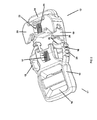
- a magnetic fastening loop 10 comprises a first plug-in element 11 intended to be introduced into a second receiving element 12 to close the fastening loop 10.
- the first plug-in element 11 comprises a molded plastic body 13 having, at one end, a first slotted device 14 for the passage of a strap, a pair of locking arms 15, 16 coplanically extending along opposite sides, and a first permanent magnet 17 housed in a first central orifice 18 of the body 13 between the two locking arms 15, 16.
- One end of each locking arm 15, 16 is secured to the door-to -false to the body 13 to allow lateral elastic deformation during the manual unlocking phase.
- the second receiving element 12 is equipped with a flat support plate 19 surmounted by a cap 20 delimiting an open space 21 for receiving the locking arms 15, 16, and a second orifice 22 in which a second permanent magnet is housed. 23.
- a second slot device 24 is provided at the rear of the cap 20 for the passage of the other end of the strap.
- the two permanent magnets 17, 23 are formed as examples by cylindrical studs magnetized magnetic material, said pads being aligned along the longitudinal axis XY.
- the permanent magnets 17, 23 may be made of a ferrous material (iron, steel, nickel, cobalt, etc.) or ferrite.
- Each permanent magnet 17, 23 comprises a pole N and a pole S, located respectively at each end of the pads.
- the poles of the two permanent magnets 17, 23 facing each other, have opposite magnetic polarities, so as to create a magnetic attraction effect between them.
- the pole N of the first permanent magnet 17 is positioned axially facing the pole S of the second permanent magnet 23.
- the lines the force of the magnetic field leaving the pole N of the first permanent magnet 17 are in the opposite direction with those entering the pole S of the second permanent magnet 23. This results in a magnetic attraction between the two magnets 17, 23, and the coming into contact of the two elements 11, 12 corresponding to the closed position of the loop (illustrated in FIG. figure 6 ).
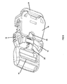
- the two locking arms 15, 16 have identical profiles and symmetrical with respect to the vertical median plane having as a trace the longitudinal axis XY.
- Each elastic locking arm 15, 16 is composed of a gripping sector 24, and a guide surface 25 terminating at the free end by a stop 26.
- the body 13 further comprises two guide lugs 30 projecting on either side of the first orifice 18 of the magnet 17 so as to contribute to the longitudinal centering of the first plug-in element 11.
- the cap 20 of the second receiver element 12 is provided with a pair of recesses 27 disposed on either side of the second orifice 22 of the magnet 23.
- the stop 26 of each locking arm 15, 16, and the guide pins 30 engage in the corresponding recesses 27 of the cap 20 to ensure both the centering and the mechanical locking in the closed position.
- the input of the support plate 19 is advantageously provided with a positioning notch 28 in which axially a protrusion 29 for guiding the body 13 during the magnetic attraction stroke is inserted axially.
- the system of the two magnets 17, 23 generates magnetic repulsion fields in the air gap capable of restoring axial guidance in the longitudinal direction XY.
Abstract
Description
L'invention concerne une boucle d'attache magnétique comprenant :
- un premier élément à enfichage équipé d'un premier aimant permanent et d'au moins un bras de verrouillage destiné à occuper une position verrouillée lors de la fermeture de la boucle, et une position déverrouillée pour l'ouverture de la boucle,
- un deuxième élément récepteur ayant un espace ouvert dans lequel s'engage le premier élément à enfichage par attraction magnétique, ledit deuxième élément récepteur comportant un deuxième aimant permanent tel que les pôles juxtaposés des deux aimants en regard l'un avec l'autre présentent des polarités magnétiques opposées.
- a first plug-in element equipped with a first permanent magnet and at least one locking arm intended to occupy a locked position when closing the loop, and an unlocked position for opening the loop,
- a second receiver element having an open space in which the first magnetic attraction plug element engages, said second receiver element comprising a second permanent magnet such that the juxtaposed poles of the two magnets facing each other have opposite magnetic polarities.
Le document
Le document
L'objet de l'invention consiste à réaliser une boucle d'attache magnétique à enclenchement rapide, et à encombrement réduit.The object of the invention is to provide a magnetic coupling loop with quick engagement, and reduced space.
La boucle d'attache selon l'invention est caractérisée en ce que le corps du premier élément à enfichage comporte une paire d'ergots de guidage faisant saillie de part et d'autre d'un premier orifice de logement du premier aimant permanent, les deux ergots de guidage étant parallèles par rapport à l'axe longitudinal de la boucle, et le deuxième élément récepteur étant doté d'une plaque d'appui plane, l'ensemble étant apte à assurer un effet d'autocentrage du premier élément à enfichage dans ladite direction longitudinale.The fastening buckle according to the invention is characterized in that the body of the first plug-in element comprises a pair of guide pins protruding on either side of a first housing orifice of the first permanent magnet, the two guide lugs being parallel with respect to the longitudinal axis of the loop, and the second receiving element being provided with a flat support plate, the assembly being able to ensure a self-centering effect of the first plug-in element in said longitudinal direction.
Cet effet d'autocentrage magnétique résulte en plus de la répartition des lignes de force des champs magnétiques des deux aimants, lesquelles sont de sens contraire de part et d'autre de l'axe longitudinal. L'attraction magnétique uniforme dans l'entrefer entre les deux aimants permanents, tend à déplacer axialement le premier élément à enfichage jusqu'à sa venue en contact avec le deuxième élément récepteur. Le maintien par attraction magnétique de la boucle en position fermée est confirmé par le blocage mécanique des bras de verrouillage dans le chapeau.This magnetic self-centering effect results in addition to the distribution of the lines of force of the magnetic fields of the two magnets, which are in opposite directions on either side of the longitudinal axis. The uniform magnetic attraction in the gap between the two permanent magnets, tends to axially move the first plug-in element until it comes into contact with the second receiver element. The maintenance by magnetic attraction of the loop in the closed position is confirmed by the mechanical locking of the locking arms in the cap.
Selon un mode de réalisation préférentiel, les deux aimants permanents sont formés par des plots cylindriques à polarisation axiale, et s'étendant en alignement avec l'axe longitudinal. Le chapeau du deuxième élément récepteur est doté d'une paire d'évidements disposés de part et d'autre d'un deuxième orifice de logement du deuxième aimant permanent, les évidements étant destinés à recevoir en position de fermeture d'attraction, lesdits ergots de guidage, ainsi que des butées prévues aux extrémités des bras de verrouillage.According to a preferred embodiment, the two permanent magnets are formed by cylindrical pins with axial polarization, and extending in alignment with the longitudinal axis. The cap of the second receiver element is provided with a pair of recesses arranged on either side of a second housing orifice of the second permanent magnet, the recesses being intended to receive in the closed position of attraction, said lugs guide, as well as stops provided at the ends of the locking arms.
Les aimants permanents peuvent être réalisés en un matériau ferreux (fer, acier, nickel, cobalt, etc..) ou en ferrite.Permanent magnets can be made of a ferrous material (iron, steel, nickel, cobalt, etc.) or ferrite.
D'autres avantages et caractéristiques ressortiront plus clairement de la description qui va suivre d'un mode de réalisation de l'invention donné à titre d'exemple non limitatif et représenté aux dessins annexés, dans lesquels :
- la
figure 1 est une vue en perspective de la boucle d'attache selon l'invention, représentée dans l'état désaccouplé ; - la
figure 2 montre une vue identique de lafigure 1 , lors de la phase d'accouplement de la boucle ; - les
figures 3 à 6 représentent des vues en plan de la boucle, respectivement en position d'ouverture au début de la phase d'insertion, puis lors du déplacement progressif par attraction magnétique le long de la plaque d'appui, et en fin de course de fermeture après verrouillage mécanique ; - les
figures 7 et8 sont des vues en perspective de dessous de la boucle, respectivement en position désaccouplée, et lors de l'insertion ; - la
figure 9 montre une vue de profil de la boucle en position de fermeture.
- the
figure 1 is a perspective view of the fastening buckle according to the invention, shown in the uncoupled state; - the
figure 2 shows an identical view of thefigure 1 during the coupling phase of the loop; - the
Figures 3 to 6 represent plane views of the loop, respectively in the open position at the beginning of the insertion phase, and during the progressive displacement by magnetic attraction along the support plate, and at the end of the closing stroke after locking. mechanical ; - the
figures 7 and8 are perspective views from below of the loop, respectively in uncoupled position, and during insertion; - the
figure 9 shows a profile view of the loop in the closed position.
Sur les figures, une boucle d'attache 10 magnétique comporte un premier élément à enfichage 11 destiné à être introduit dans un deuxième élément récepteur 12 pour assurer la fermeture de la boucle d'attache 10.In the figures, a
Le premier élément à enfichage 11 comprend un corps 13 en matière plastique moulée, ayant à l'une des extrémités un premier dispositif à fentes 14 pour le passage d'une sangle, une paire de bras de verrouillage 15, 16 s'étendant coplanairement le long des côtés opposés, et un premier aimant permanent 17 logé dans un premier orifice 18 central du corps 13 entre les deux bras de verrouillage 15, 16. L'une des extrémités de chaque bras de verrouillage 15, 16 est solidarisée en porte-à-faux au corps 13 pour permettre une déformation élastique latérale lors de la phase manuelle de déverrouillage.The first plug-in
Le deuxième élément récepteur 12 est équipé d'une plaque d'appui 19 plane surmontée d'un chapeau 20 délimitant un espace 21 ouvert de réception des bras de verrouillage 15, 16, et un deuxième orifice 22 dans lequel est logé un deuxième aimant permanent 23. Un deuxième dispositif à fentes 24 est prévu à l'arrière du chapeau 20 pour le passage de l'autre bout de sangle.The second receiving
Les deux aimants permanents 17, 23 sont formés à titre d'exemples par des plots cylindriques en matière magnétique aimantée, lesdits plots étant alignés selon l'axe longitudinal XY. Les aimants permanents 17, 23 peuvent être réalisés en un matériau ferreux (fer, acier, nickel, cobalt, etc..) ou en ferrite. Chaque aimant permanent 17, 23 comprend un pôle N et un pôle S, situé respectivement à chaque extrémité des plots. Les pôles des deux aimants permanents 17, 23 se faisant face, présentent des polarités magnétiques opposées, de manière à créer un effet d'attraction magnétique entre eux.The two
Comme le montre à titre d'exemple la
Les deux bras de verrouillage 15, 16 présentent des profils identiques et symétriques par rapport au plan médian vertical ayant comme trace l'axe longitudinal XY. Chaque bras de verrouillage 15, 16 élastique est composé d'un secteur de préhension 24, et d'une surface de guidage 25 se terminant à l'extrémité libre par une butée 26.The two locking
Le corps 13 comporte en plus deux ergots de guidage 30 faisant saillie de part et d'autre du premier orifice 18 de l'aimant 17 de manière à contribuer au centrage longitudinal du premier élément à enfichage 11.The
Le chapeau 20 du deuxième élément récepteur 12 est doté d'une paire d'évidements 27 disposés de part et d'autre du deuxième orifice 22 de l'aimant 23. En fin de course de fermeture de la boucle, la butée 26 de chaque bras de verrouillage 15, 16, et les ergots de guidage 30 s'engagent dans les évidements 27 correspondants du chapeau 20 pour assurer à la fois le centrage et le verrouillage mécanique en position de fermeture.The
L'entrée de la plaque d'appui 19 est munie avantageusement d'une encoche 28 de positionnement dans laquelle s'insère axialement une protubérance 29 de guidage du corps 13 pendant la course d'attraction magnétique.The input of the
La fermeture et l'ouverture de la boucle d'attache 10 magnétique s'effectuent de la manière suivante :
- A partir de la position d'ouverture représentée à la
figure 3 , il suffit d'approcher le premier élément àenfichage 11 dudeuxième élément récepteur 12 pour que s'établisse l'attraction magnétique entre les deux aimants permanents 17, 23. Les deux bras deverrouillage chapeau 20, l'attraction magnétique augmentant avec la diminution de l'entrefer entre les deuxaimants
- From the open position represented at
figure 3 it is sufficient to approach the first plug-inelement 11 of the second receivingelement 12 so that the magnetic attraction between the twopermanent magnets arms support plate 19 towards thecap 20, the magnetic attraction increasing with the decrease of the gap between the twomagnets
Dans la position centrée de la
Il est indispensable que le rapprochement du premier élément à enfichage 11 se fasse le long et au-dessus de la plaque d'appui 19 du deuxième élément récepteur 12. En cas d'une inclinaison ou d'un positionnement aléatoire du premier élément à enfichage 11, le système des deux aimants 17, 23 engendre des champs magnétiques de répulsion dans l'entrefer susceptibles de rétablir un guidage axial dans la direction longitudinale XY.It is essential that the approximation of the first plug-in
Pour ouvrir la boucle, il suffit de pincer latéralement entre deux doigts les bras de verrouillage 15, 16 dans les sens opposés des flèches F1 et F2 pour assurer le déverrouillage mécanique. On exerce ensuite une traction axiale manuelle sur le premier élément à enfichage 11 en l'éloignant du deuxième élément récepteur 12, la force de traction étant opposée et supérieure à la force d'attraction magnétique des aimants 17, 23.To open the loop, it is sufficient to pinch laterally between two fingers the locking
Claims (4)
Applications Claiming Priority (1)
| Application Number | Priority Date | Filing Date | Title |
|---|---|---|---|
| FR1101039A FR2973659B1 (en) | 2011-04-06 | 2011-04-06 | MAGNETIC ATTACHING LOOP WITH PERMANENT MAGNETS AND MECHANICAL LOCKING |
Publications (2)
| Publication Number | Publication Date |
|---|---|
| EP2508095A1 true EP2508095A1 (en) | 2012-10-10 |
| EP2508095B1 EP2508095B1 (en) | 2015-05-20 |
Family
ID=45932257
Family Applications (1)
| Application Number | Title | Priority Date | Filing Date |
|---|---|---|---|
| EP20120354026 Active EP2508095B1 (en) | 2011-04-06 | 2012-04-02 | Magnetic attachment loop with permanent magnets and mechanical locking |
Country Status (5)
| Country | Link |
|---|---|
| US (1) | US8914951B2 (en) |
| EP (1) | EP2508095B1 (en) |
| CN (1) | CN102726891B (en) |
| ES (1) | ES2543155T3 (en) |
| FR (1) | FR2973659B1 (en) |
Cited By (6)
| Publication number | Priority date | Publication date | Assignee | Title |
|---|---|---|---|---|
| FR3026280A1 (en) * | 2014-09-25 | 2016-04-01 | Zedel | MAGNETIC ATTACHING LOOP WITH PERMANENT MAGNETS AND MECHANICAL LOCKING |
| WO2019063948A2 (en) | 2017-09-29 | 2019-04-04 | Birota | Human-powered vehicle suitable for compact storage |
| EP3494826A1 (en) * | 2017-12-07 | 2019-06-12 | Wonderland Switzerland AG | Magnetic buckling assembly |
| WO2021197222A1 (en) * | 2020-03-30 | 2021-10-07 | Duraflex Hong Kong Limited | Attachment system with quick release |
| US11140946B2 (en) | 2019-06-06 | 2021-10-12 | Wonderland Switzerland Ag | Magnetic buckle assembly |
| US11925241B2 (en) | 2019-07-17 | 2024-03-12 | Wonderland Switzerland Ag | Buckle assembly |
Families Citing this family (25)
| Publication number | Priority date | Publication date | Assignee | Title |
|---|---|---|---|---|
| KR101230729B1 (en) * | 2009-03-31 | 2013-02-07 | 와이케이케이 가부시끼가이샤 | Side release buckle |
| US20130269629A1 (en) * | 2012-04-13 | 2013-10-17 | Coastal Pet Products, Inc. | Magnetic buckle for a pet collar or the like |
| EP2833754B1 (en) * | 2012-12-14 | 2016-04-27 | Fidlock GmbH | Closure device for detachably connecting two parts |
| JP6286534B2 (en) | 2013-05-08 | 2018-02-28 | フィドロック・ゲーエムベーハーFidlock Gmbh | Closure device |
| CN103284408A (en) * | 2013-05-17 | 2013-09-11 | 国家电网公司 | Safety belt magnetic buckle |
| AT514652B1 (en) * | 2013-07-25 | 2015-08-15 | Edgar Lill | Buckle with magnetic closure |
| WO2015084583A1 (en) * | 2013-12-04 | 2015-06-11 | Happy Fig, LLC | Clothing clip apparatus and method for using same |
| US9307808B1 (en) * | 2015-01-19 | 2016-04-12 | Duraflex Hong Kong Limited | Magnetic buckle assembly |
| KR101777109B1 (en) * | 2015-11-05 | 2017-09-12 | 주식회사 우진프라스틱 | buckle |
| KR101811501B1 (en) * | 2015-12-22 | 2017-12-20 | 백지숙 | Buckle for shoulder strap of knapsack |
| US10045866B2 (en) * | 2016-04-01 | 2018-08-14 | Michael Armbruster | Prosthetic attachment |
| US10111500B2 (en) * | 2016-11-08 | 2018-10-30 | Brian Lambert | Self-aligning, quick connect and disconnect magnetic end connectors |
| TWI584755B (en) * | 2016-11-16 | 2017-06-01 | 倍騰國際股份有限公司 | Magnetic Buckle |
| DE102018201019A1 (en) | 2017-02-28 | 2018-08-30 | Fidlock Gmbh | Closure device with a winding element |
| WO2018160716A1 (en) * | 2017-03-01 | 2018-09-07 | Carrier Corporation | Locking module |
| IT201700067329A1 (en) * | 2017-06-16 | 2018-12-16 | Ferplast Spa | AUTOMATIC BUCKLE |
| US10470529B2 (en) * | 2017-06-21 | 2019-11-12 | Duraflex Hong Kong Limited | Magnet hook |
| CN114794675A (en) * | 2017-12-07 | 2022-07-29 | 明门瑞士股份有限公司 | Magnetic fastener |
| US10655657B2 (en) * | 2018-05-28 | 2020-05-19 | Travis Hurley | Connecting apparatus |
| US10945476B2 (en) * | 2018-11-20 | 2021-03-16 | Shenzhen City Aikang Weida Intelligent medical technology co., ltd | Mechanical-magnetic locking device |
| KR102188857B1 (en) * | 2019-05-14 | 2020-12-09 | 주식회사 우진프라스틱 | Buckle having strong coupling function and improved release function |
| US11006699B1 (en) | 2020-02-02 | 2021-05-18 | Peter Goodwin | Magnetic buckle |
| US11540649B2 (en) | 2020-04-14 | 2023-01-03 | Dorel Juvenile Group, Inc. | Carry handle anchor system |
| USD1004480S1 (en) * | 2020-10-22 | 2023-11-14 | Duraflex Hong Kong Limited | Buckle |
| CN114715001B (en) * | 2022-03-24 | 2023-08-04 | 好孩子儿童用品有限公司 | Magnetic hasp |
Citations (5)
| Publication number | Priority date | Publication date | Assignee | Title |
|---|---|---|---|---|
| US4991272A (en) * | 1988-08-09 | 1991-02-12 | Bianchi John E | Quick release buckle |
| EP1243192A2 (en) * | 2001-03-23 | 2002-09-25 | Ykk Corporation | Separable buckle |
| WO2008006355A2 (en) | 2006-07-12 | 2008-01-17 | Fidlock Gmbh | Magnetic quick-release buckle comprising a mechanical lock |
| WO2009010049A2 (en) * | 2007-07-17 | 2009-01-22 | Fidlock Gmbh | Mechanical/magnetic connecting structure |
| WO2009103279A2 (en) | 2008-02-21 | 2009-08-27 | Fidlock Gmbh | Magnetomechanical connection assembly with load securing |
Family Cites Families (11)
| Publication number | Priority date | Publication date | Assignee | Title |
|---|---|---|---|---|
| US2615227A (en) * | 1949-11-18 | 1952-10-28 | Hornik Frederick | Magnetic clasp coupling for jewelry |
| US3589341A (en) * | 1969-09-24 | 1971-06-29 | Jacob Krebs | Animal collar with magnetic fastener |
| US5311647A (en) * | 1990-06-12 | 1994-05-17 | Davida Levy | Jewelry closure having both magnetic and mechanical clasps |
| US6363584B1 (en) * | 2000-01-20 | 2002-04-02 | George Gero | Cuff link with changeable element |
| US6857169B2 (en) * | 2002-12-10 | 2005-02-22 | Taiwan Industrial Fastener Corporation | Structure of magnetic buckle |
| JP2004358067A (en) * | 2003-06-06 | 2004-12-24 | Rakusesu:Kk | Connector of accessory or the like |
| ITVI20040047A1 (en) * | 2004-03-11 | 2004-06-11 | Cost Cast Srl | CLOSURE FOR CLOSURE TO BE APPLIED ON JEWELERY AND JEWELERY PRODUCTS AND ON ACCESSORIES FOR CLOTHING, BAGS AND SIMILAR |
| JP2006219964A (en) * | 2005-02-09 | 2006-08-24 | Yochi Kaihatsu Kk | Fixing implement |
| US7523527B2 (en) * | 2006-08-22 | 2009-04-28 | Garber Michael I | Clasp for chains and the like |
| WO2008116152A2 (en) * | 2007-03-21 | 2008-09-25 | I.B. Goodman Mfg Company, Inc. | Magnetic clasp |
| US8427294B2 (en) * | 2008-03-31 | 2013-04-23 | The Boeing Company | Seat buckle configured for security and safety and associated methods |
-
2011
- 2011-04-06 FR FR1101039A patent/FR2973659B1/en not_active Expired - Fee Related
-
2012
- 2012-04-02 EP EP20120354026 patent/EP2508095B1/en active Active
- 2012-04-02 ES ES12354026.2T patent/ES2543155T3/en active Active
- 2012-04-06 CN CN201210184758.6A patent/CN102726891B/en active Active
- 2012-04-06 US US13/441,256 patent/US8914951B2/en active Active
Patent Citations (5)
| Publication number | Priority date | Publication date | Assignee | Title |
|---|---|---|---|---|
| US4991272A (en) * | 1988-08-09 | 1991-02-12 | Bianchi John E | Quick release buckle |
| EP1243192A2 (en) * | 2001-03-23 | 2002-09-25 | Ykk Corporation | Separable buckle |
| WO2008006355A2 (en) | 2006-07-12 | 2008-01-17 | Fidlock Gmbh | Magnetic quick-release buckle comprising a mechanical lock |
| WO2009010049A2 (en) * | 2007-07-17 | 2009-01-22 | Fidlock Gmbh | Mechanical/magnetic connecting structure |
| WO2009103279A2 (en) | 2008-02-21 | 2009-08-27 | Fidlock Gmbh | Magnetomechanical connection assembly with load securing |
Cited By (14)
| Publication number | Priority date | Publication date | Assignee | Title |
|---|---|---|---|---|
| FR3026280A1 (en) * | 2014-09-25 | 2016-04-01 | Zedel | MAGNETIC ATTACHING LOOP WITH PERMANENT MAGNETS AND MECHANICAL LOCKING |
| WO2019063948A2 (en) | 2017-09-29 | 2019-04-04 | Birota | Human-powered vehicle suitable for compact storage |
| EP3494826A1 (en) * | 2017-12-07 | 2019-06-12 | Wonderland Switzerland AG | Magnetic buckling assembly |
| US10874178B2 (en) | 2017-12-07 | 2020-12-29 | Wonderland Switzerland Ag | Magnetic buckling assembly |
| US11903455B2 (en) | 2017-12-07 | 2024-02-20 | Wonderland Switzerland Ag | Female buckling component for magnetic buckling assembly |
| US11758988B2 (en) | 2017-12-07 | 2023-09-19 | Wonderland Switzerland Ag | Magnetic buckling assembly |
| US11758987B2 (en) | 2017-12-07 | 2023-09-19 | Wonderland Switzerland Ag | Magnetic buckling assembly |
| US11712090B2 (en) | 2019-06-06 | 2023-08-01 | Wonderland Switzerland Ag | Magnetic buckle assembly |
| AU2020203755B2 (en) * | 2019-06-06 | 2022-06-16 | Wonderland Switzerland Ag | Magnetic buckle assembly |
| US11140946B2 (en) | 2019-06-06 | 2021-10-12 | Wonderland Switzerland Ag | Magnetic buckle assembly |
| US11925241B2 (en) | 2019-07-17 | 2024-03-12 | Wonderland Switzerland Ag | Buckle assembly |
| CN114126443B (en) * | 2020-03-30 | 2023-06-16 | 力顿钮扣配件(深圳)有限公司 | Attachment system with quick release |
| CN114126443A (en) * | 2020-03-30 | 2022-03-01 | 力顿钮扣配件(深圳)有限公司 | Attachment system with quick release |
| WO2021197222A1 (en) * | 2020-03-30 | 2021-10-07 | Duraflex Hong Kong Limited | Attachment system with quick release |
Also Published As
| Publication number | Publication date |
|---|---|
| ES2543155T3 (en) | 2015-08-17 |
| CN102726891B (en) | 2016-01-20 |
| US8914951B2 (en) | 2014-12-23 |
| FR2973659B1 (en) | 2014-04-04 |
| EP2508095B1 (en) | 2015-05-20 |
| FR2973659A1 (en) | 2012-10-12 |
| US20120255144A1 (en) | 2012-10-11 |
| CN102726891A (en) | 2012-10-17 |
Similar Documents
| Publication | Publication Date | Title |
|---|---|---|
| EP2508095B1 (en) | Magnetic attachment loop with permanent magnets and mechanical locking | |
| EP3343740B1 (en) | Power generation device | |
| CN101657120B (en) | Mechanic-magnetic connecting structure | |
| US20140339232A1 (en) | Closure Device | |
| US8430434B2 (en) | Mechanical-magnetic connecting structure | |
| US20130135067A1 (en) | Magnet substance holder including a combination of a permanent magnet and an electromagnet | |
| EP1776210B1 (en) | Multipurpose fixing magnetic semi-clamp | |
| US9635919B2 (en) | Closure device | |
| US8899636B2 (en) | Magnetic latch | |
| JP2006149824A (en) | Zipper | |
| FR2681721A1 (en) | MAGNETIC ASSEMBLY FOR MAGNET CLASP. | |
| FR3062689A1 (en) | COLLAR FOR FIXING A CONDUIT ON A SUPPORT. | |
| WO2006041712A1 (en) | Magnetic spring clamp | |
| FR2742101A1 (en) | HEADREST ATTACHMENT | |
| US20130076463A1 (en) | Electromagnetic contactor and assembly method for the same | |
| FR2522107A1 (en) | MAGNETIC VALVE WITH MAGNETIC DRIVE | |
| FR3026280A1 (en) | MAGNETIC ATTACHING LOOP WITH PERMANENT MAGNETS AND MECHANICAL LOCKING | |
| EP0256939A1 (en) | Current-measuring device | |
| CN216393257U (en) | Pulling force is inhaled to portable magnetism and is buckled | |
| CN110892591B (en) | Closure device with electrical contacts | |
| KR101814637B1 (en) | Equipment for connecting a underground line | |
| WO2020202010A1 (en) | Magnetic seating for fiber optic component | |
| FR3002475A1 (en) | FIXING DEVICE, IN PARTICULAR FOR A CLAMPING TOOL | |
| EP1701045A1 (en) | Device of assembly of an element of connection on a fixed support | |
| JP2729768B2 (en) | magnet catch |
Legal Events
| Date | Code | Title | Description |
|---|---|---|---|
| PUAI | Public reference made under article 153(3) epc to a published international application that has entered the european phase |
Free format text: ORIGINAL CODE: 0009012 |
|
| AK | Designated contracting states |
Kind code of ref document: A1 Designated state(s): AL AT BE BG CH CY CZ DE DK EE ES FI FR GB GR HR HU IE IS IT LI LT LU LV MC MK MT NL NO PL PT RO RS SE SI SK SM TR |
|
| AX | Request for extension of the european patent |
Extension state: BA ME |
|
| 17P | Request for examination filed |
Effective date: 20130329 |
|
| RIC1 | Information provided on ipc code assigned before grant |
Ipc: A44B 11/26 20060101AFI20141008BHEP Ipc: A45C 13/10 20060101ALI20141008BHEP |
|
| GRAP | Despatch of communication of intention to grant a patent |
Free format text: ORIGINAL CODE: EPIDOSNIGR1 |
|
| INTG | Intention to grant announced |
Effective date: 20141120 |
|
| GRAS | Grant fee paid |
Free format text: ORIGINAL CODE: EPIDOSNIGR3 |
|
| GRAA | (expected) grant |
Free format text: ORIGINAL CODE: 0009210 |
|
| AK | Designated contracting states |
Kind code of ref document: B1 Designated state(s): AL AT BE BG CH CY CZ DE DK EE ES FI FR GB GR HR HU IE IS IT LI LT LU LV MC MK MT NL NO PL PT RO RS SE SI SK SM TR |
|
| REG | Reference to a national code |
Ref country code: GB Ref legal event code: FG4D Free format text: NOT ENGLISH |
|
| REG | Reference to a national code |
Ref country code: CH Ref legal event code: EP |
|
| REG | Reference to a national code |
Ref country code: AT Ref legal event code: REF Ref document number: 727262 Country of ref document: AT Kind code of ref document: T Effective date: 20150615 |
|
| REG | Reference to a national code |
Ref country code: IE Ref legal event code: FG4D Free format text: LANGUAGE OF EP DOCUMENT: FRENCH |
|
| REG | Reference to a national code |
Ref country code: DE Ref legal event code: R096 Ref document number: 602012007401 Country of ref document: DE |
|
| REG | Reference to a national code |
Ref country code: CH Ref legal event code: NV Representative=s name: CABINET ROLAND NITHARDT CONSEILS EN PROPRIETE , CH |
|
| REG | Reference to a national code |
Ref country code: ES Ref legal event code: FG2A Ref document number: 2543155 Country of ref document: ES Kind code of ref document: T3 Effective date: 20150817 |
|
| REG | Reference to a national code |
Ref country code: LT Ref legal event code: MG4D |
|
| REG | Reference to a national code |
Ref country code: NL Ref legal event code: MP Effective date: 20150520 |
|
| PG25 | Lapsed in a contracting state [announced via postgrant information from national office to epo] |
Ref country code: NO Free format text: LAPSE BECAUSE OF FAILURE TO SUBMIT A TRANSLATION OF THE DESCRIPTION OR TO PAY THE FEE WITHIN THE PRESCRIBED TIME-LIMIT Effective date: 20150820 Ref country code: PT Free format text: LAPSE BECAUSE OF FAILURE TO SUBMIT A TRANSLATION OF THE DESCRIPTION OR TO PAY THE FEE WITHIN THE PRESCRIBED TIME-LIMIT Effective date: 20150921 Ref country code: LT Free format text: LAPSE BECAUSE OF FAILURE TO SUBMIT A TRANSLATION OF THE DESCRIPTION OR TO PAY THE FEE WITHIN THE PRESCRIBED TIME-LIMIT Effective date: 20150520 Ref country code: FI Free format text: LAPSE BECAUSE OF FAILURE TO SUBMIT A TRANSLATION OF THE DESCRIPTION OR TO PAY THE FEE WITHIN THE PRESCRIBED TIME-LIMIT Effective date: 20150520 Ref country code: HR Free format text: LAPSE BECAUSE OF FAILURE TO SUBMIT A TRANSLATION OF THE DESCRIPTION OR TO PAY THE FEE WITHIN THE PRESCRIBED TIME-LIMIT Effective date: 20150520 |
|
| PG25 | Lapsed in a contracting state [announced via postgrant information from national office to epo] |
Ref country code: BG Free format text: LAPSE BECAUSE OF FAILURE TO SUBMIT A TRANSLATION OF THE DESCRIPTION OR TO PAY THE FEE WITHIN THE PRESCRIBED TIME-LIMIT Effective date: 20150820 Ref country code: LV Free format text: LAPSE BECAUSE OF FAILURE TO SUBMIT A TRANSLATION OF THE DESCRIPTION OR TO PAY THE FEE WITHIN THE PRESCRIBED TIME-LIMIT Effective date: 20150520 Ref country code: IS Free format text: LAPSE BECAUSE OF FAILURE TO SUBMIT A TRANSLATION OF THE DESCRIPTION OR TO PAY THE FEE WITHIN THE PRESCRIBED TIME-LIMIT Effective date: 20150920 Ref country code: RS Free format text: LAPSE BECAUSE OF FAILURE TO SUBMIT A TRANSLATION OF THE DESCRIPTION OR TO PAY THE FEE WITHIN THE PRESCRIBED TIME-LIMIT Effective date: 20150520 Ref country code: GR Free format text: LAPSE BECAUSE OF FAILURE TO SUBMIT A TRANSLATION OF THE DESCRIPTION OR TO PAY THE FEE WITHIN THE PRESCRIBED TIME-LIMIT Effective date: 20150821 |
|
| PG25 | Lapsed in a contracting state [announced via postgrant information from national office to epo] |
Ref country code: DK Free format text: LAPSE BECAUSE OF FAILURE TO SUBMIT A TRANSLATION OF THE DESCRIPTION OR TO PAY THE FEE WITHIN THE PRESCRIBED TIME-LIMIT Effective date: 20150520 Ref country code: EE Free format text: LAPSE BECAUSE OF FAILURE TO SUBMIT A TRANSLATION OF THE DESCRIPTION OR TO PAY THE FEE WITHIN THE PRESCRIBED TIME-LIMIT Effective date: 20150520 |
|
| REG | Reference to a national code |
Ref country code: AT Ref legal event code: UEP Ref document number: 727262 Country of ref document: AT Kind code of ref document: T Effective date: 20150520 |
|
| REG | Reference to a national code |
Ref country code: DE Ref legal event code: R097 Ref document number: 602012007401 Country of ref document: DE |
|
| PG25 | Lapsed in a contracting state [announced via postgrant information from national office to epo] |
Ref country code: SK Free format text: LAPSE BECAUSE OF FAILURE TO SUBMIT A TRANSLATION OF THE DESCRIPTION OR TO PAY THE FEE WITHIN THE PRESCRIBED TIME-LIMIT Effective date: 20150520 Ref country code: PL Free format text: LAPSE BECAUSE OF FAILURE TO SUBMIT A TRANSLATION OF THE DESCRIPTION OR TO PAY THE FEE WITHIN THE PRESCRIBED TIME-LIMIT Effective date: 20150520 Ref country code: RO Free format text: LAPSE BECAUSE OF NON-PAYMENT OF DUE FEES Effective date: 20150520 |
|
| REG | Reference to a national code |
Ref country code: FR Ref legal event code: PLFP Year of fee payment: 5 |
|
| PLBE | No opposition filed within time limit |
Free format text: ORIGINAL CODE: 0009261 |
|
| STAA | Information on the status of an ep patent application or granted ep patent |
Free format text: STATUS: NO OPPOSITION FILED WITHIN TIME LIMIT |
|
| 26N | No opposition filed |
Effective date: 20160223 |
|
| PG25 | Lapsed in a contracting state [announced via postgrant information from national office to epo] |
Ref country code: SI Free format text: LAPSE BECAUSE OF FAILURE TO SUBMIT A TRANSLATION OF THE DESCRIPTION OR TO PAY THE FEE WITHIN THE PRESCRIBED TIME-LIMIT Effective date: 20150520 |
|
| PG25 | Lapsed in a contracting state [announced via postgrant information from national office to epo] |
Ref country code: BE Free format text: LAPSE BECAUSE OF NON-PAYMENT OF DUE FEES Effective date: 20160430 |
|
| PG25 | Lapsed in a contracting state [announced via postgrant information from national office to epo] |
Ref country code: LU Free format text: LAPSE BECAUSE OF FAILURE TO SUBMIT A TRANSLATION OF THE DESCRIPTION OR TO PAY THE FEE WITHIN THE PRESCRIBED TIME-LIMIT Effective date: 20160402 |
|
| REG | Reference to a national code |
Ref country code: IE Ref legal event code: MM4A |
|
| REG | Reference to a national code |
Ref country code: FR Ref legal event code: PLFP Year of fee payment: 6 |
|
| PG25 | Lapsed in a contracting state [announced via postgrant information from national office to epo] |
Ref country code: IE Free format text: LAPSE BECAUSE OF NON-PAYMENT OF DUE FEES Effective date: 20160402 |
|
| PG25 | Lapsed in a contracting state [announced via postgrant information from national office to epo] |
Ref country code: SE Free format text: LAPSE BECAUSE OF FAILURE TO SUBMIT A TRANSLATION OF THE DESCRIPTION OR TO PAY THE FEE WITHIN THE PRESCRIBED TIME-LIMIT Effective date: 20150520 Ref country code: NL Free format text: LAPSE BECAUSE OF FAILURE TO SUBMIT A TRANSLATION OF THE DESCRIPTION OR TO PAY THE FEE WITHIN THE PRESCRIBED TIME-LIMIT Effective date: 20150520 |
|
| REG | Reference to a national code |
Ref country code: FR Ref legal event code: PLFP Year of fee payment: 7 |
|
| PG25 | Lapsed in a contracting state [announced via postgrant information from national office to epo] |
Ref country code: SM Free format text: LAPSE BECAUSE OF FAILURE TO SUBMIT A TRANSLATION OF THE DESCRIPTION OR TO PAY THE FEE WITHIN THE PRESCRIBED TIME-LIMIT Effective date: 20150520 Ref country code: CY Free format text: LAPSE BECAUSE OF FAILURE TO SUBMIT A TRANSLATION OF THE DESCRIPTION OR TO PAY THE FEE WITHIN THE PRESCRIBED TIME-LIMIT Effective date: 20150520 Ref country code: HU Free format text: LAPSE BECAUSE OF FAILURE TO SUBMIT A TRANSLATION OF THE DESCRIPTION OR TO PAY THE FEE WITHIN THE PRESCRIBED TIME-LIMIT; INVALID AB INITIO Effective date: 20120402 |
|
| PG25 | Lapsed in a contracting state [announced via postgrant information from national office to epo] |
Ref country code: MK Free format text: LAPSE BECAUSE OF FAILURE TO SUBMIT A TRANSLATION OF THE DESCRIPTION OR TO PAY THE FEE WITHIN THE PRESCRIBED TIME-LIMIT Effective date: 20150520 Ref country code: MT Free format text: LAPSE BECAUSE OF FAILURE TO SUBMIT A TRANSLATION OF THE DESCRIPTION OR TO PAY THE FEE WITHIN THE PRESCRIBED TIME-LIMIT Effective date: 20150520 Ref country code: MC Free format text: LAPSE BECAUSE OF FAILURE TO SUBMIT A TRANSLATION OF THE DESCRIPTION OR TO PAY THE FEE WITHIN THE PRESCRIBED TIME-LIMIT Effective date: 20150520 Ref country code: TR Free format text: LAPSE BECAUSE OF FAILURE TO SUBMIT A TRANSLATION OF THE DESCRIPTION OR TO PAY THE FEE WITHIN THE PRESCRIBED TIME-LIMIT Effective date: 20150520 |
|
| PG25 | Lapsed in a contracting state [announced via postgrant information from national office to epo] |
Ref country code: AL Free format text: LAPSE BECAUSE OF FAILURE TO SUBMIT A TRANSLATION OF THE DESCRIPTION OR TO PAY THE FEE WITHIN THE PRESCRIBED TIME-LIMIT Effective date: 20150520 |
|
| PGFP | Annual fee paid to national office [announced via postgrant information from national office to epo] |
Ref country code: FR Payment date: 20230309 Year of fee payment: 12 Ref country code: CZ Payment date: 20230316 Year of fee payment: 12 |
|
| PGFP | Annual fee paid to national office [announced via postgrant information from national office to epo] |
Ref country code: IT Payment date: 20230310 Year of fee payment: 12 Ref country code: GB Payment date: 20230302 Year of fee payment: 12 |
|
| PGFP | Annual fee paid to national office [announced via postgrant information from national office to epo] |
Ref country code: ES Payment date: 20230511 Year of fee payment: 12 Ref country code: DE Payment date: 20230307 Year of fee payment: 12 Ref country code: CH Payment date: 20230502 Year of fee payment: 12 |
|
| PGFP | Annual fee paid to national office [announced via postgrant information from national office to epo] |
Ref country code: AT Payment date: 20230327 Year of fee payment: 12 |
|
| PGFP | Annual fee paid to national office [announced via postgrant information from national office to epo] |
Ref country code: CZ Payment date: 20240320 Year of fee payment: 13 |