EP2507481B1 - Verfahren zum betrieb einer dampfturbine und dampfturbine - Google Patents
Verfahren zum betrieb einer dampfturbine und dampfturbine Download PDFInfo
- Publication number
- EP2507481B1 EP2507481B1 EP10779767.2A EP10779767A EP2507481B1 EP 2507481 B1 EP2507481 B1 EP 2507481B1 EP 10779767 A EP10779767 A EP 10779767A EP 2507481 B1 EP2507481 B1 EP 2507481B1
- Authority
- EP
- European Patent Office
- Prior art keywords
- precursor
- steam
- atomizer
- particles
- steam turbine
- Prior art date
- Legal status (The legal status is an assumption and is not a legal conclusion. Google has not performed a legal analysis and makes no representation as to the accuracy of the status listed.)
- Not-in-force
Links
Images


Classifications
-
- F—MECHANICAL ENGINEERING; LIGHTING; HEATING; WEAPONS; BLASTING
- F01—MACHINES OR ENGINES IN GENERAL; ENGINE PLANTS IN GENERAL; STEAM ENGINES
- F01D—NON-POSITIVE DISPLACEMENT MACHINES OR ENGINES, e.g. STEAM TURBINES
- F01D25/00—Component parts, details, or accessories, not provided for in, or of interest apart from, other groups
- F01D25/007—Preventing corrosion
-
- F—MECHANICAL ENGINEERING; LIGHTING; HEATING; WEAPONS; BLASTING
- F01—MACHINES OR ENGINES IN GENERAL; ENGINE PLANTS IN GENERAL; STEAM ENGINES
- F01D—NON-POSITIVE DISPLACEMENT MACHINES OR ENGINES, e.g. STEAM TURBINES
- F01D25/00—Component parts, details, or accessories, not provided for in, or of interest apart from, other groups
- F01D25/32—Collecting of condensation water; Drainage ; Removing solid particles
-
- F—MECHANICAL ENGINEERING; LIGHTING; HEATING; WEAPONS; BLASTING
- F01—MACHINES OR ENGINES IN GENERAL; ENGINE PLANTS IN GENERAL; STEAM ENGINES
- F01K—STEAM ENGINE PLANTS; STEAM ACCUMULATORS; ENGINE PLANTS NOT OTHERWISE PROVIDED FOR; ENGINES USING SPECIAL WORKING FLUIDS OR CYCLES
- F01K7/00—Steam engine plants characterised by the use of specific types of engine; Plants or engines characterised by their use of special steam systems, cycles or processes; Control means specially adapted for such systems, cycles or processes; Use of withdrawn or exhaust steam for feed-water heating
- F01K7/06—Steam engine plants characterised by the use of specific types of engine; Plants or engines characterised by their use of special steam systems, cycles or processes; Control means specially adapted for such systems, cycles or processes; Use of withdrawn or exhaust steam for feed-water heating the engines being of multiple-inlet-pressure type
-
- F—MECHANICAL ENGINEERING; LIGHTING; HEATING; WEAPONS; BLASTING
- F02—COMBUSTION ENGINES; HOT-GAS OR COMBUSTION-PRODUCT ENGINE PLANTS
- F02C—GAS-TURBINE PLANTS; AIR INTAKES FOR JET-PROPULSION PLANTS; CONTROLLING FUEL SUPPLY IN AIR-BREATHING JET-PROPULSION PLANTS
- F02C7/00—Features, components parts, details or accessories, not provided for in, or of interest apart form groups F02C1/00 - F02C6/00; Air intakes for jet-propulsion plants
- F02C7/30—Preventing corrosion or unwanted deposits in gas-swept spaces
-
- F—MECHANICAL ENGINEERING; LIGHTING; HEATING; WEAPONS; BLASTING
- F05—INDEXING SCHEMES RELATING TO ENGINES OR PUMPS IN VARIOUS SUBCLASSES OF CLASSES F01-F04
- F05D—INDEXING SCHEME FOR ASPECTS RELATING TO NON-POSITIVE-DISPLACEMENT MACHINES OR ENGINES, GAS-TURBINES OR JET-PROPULSION PLANTS
- F05D2260/00—Function
- F05D2260/95—Preventing corrosion
Definitions
- the invention relates to a method for operating a steam turbine according to claim 1, an associated steam turbine comprising steam-operated turbine blades and a steam supply line to the turbine blades, and an atomizer for use in the steam turbine according to claim 4.
- Steam turbines are generally known in the art and usually form part of a cycle process, which is also called steam turbine process.
- This water is heated in a steam generator and flows as steam in the steam turbine.
- the steam turbine the steam relaxes and thus drives the turbine and a connected generator.
- the condenser the steam is then cooled and condensed again to water. For example, by means of a pump, the condensed water is brought back to the pressure in the steam generator and pumped there.
- the invention is therefore based on the object of specifying a method for operating a steam turbine and an associated steam turbine, in which the condensation properties are improved as possible without harmful effects on the steam turbine to achieve a higher efficiency.
- a method for operating a steam turbine in which the steam to be introduced into the steam turbine with insoluble, condensation nuclei forming particles is added.
- the idea of the present invention is therefore to add water-insoluble particles which can serve as condensation nuclei.
- the prerequisite for this is that the condensation nuclei, ie the particles, have a low contact angle to water.
- An example of condensation nuclei known from the prior art are silver iodide particles (AgI). This substance is currently being used when it is necessary to force rain clouds down in the atmosphere. According to the invention, however, it is preferred that the particles consist of titanium dioxide. Titanium dioxide as a material for the particles can also be used to produce very small, insoluble particles with a low contact angle to water.
- spherical particles can be used whose Size is in the range of 2 - 250 nm.
- nanoparticles are used whose size ranges from 1 to 100 nm.
- it can also be provided to allow agglomeration of spherical particles to larger particles in a first approximation.
- the water-insoluble particles are thus introduced into the vapor stream before reaching the turbine blades. Since the particles are not soluble in water, corrosion is avoided. Furthermore, very small particles, in particular nanoparticles, are used, as this material can be saved and erosion by collision of the particles or droplets can be reduced with the blades.
- the particles serve as condensation nuclei, so that supersaturation is counteracted. Ideally, this can even be avoided. It results in a timely condensation with many small droplets, especially when very small particles are used. In this way, finally, the efficiency of the steam turbine is increased and there is less drop impact erosion.
- the particles act in the last stages of the steam turbine, mainly in the region where supersaturation can occur.
- the particles should as far as possible be introduced into the vapor stream in such a way that they are distributed over the entire cross-section of the vapor stream within the steam turbine. In this way, the positive properties of the present invention affect the entire vapor stream.
- insoluble particles in a vapor stream can bring practical difficulties. Because in solid form, particles, especially nanoparticles, on the one hand only bad transport, on the other hand For example, macroscopic methods of solids extraction from process engineering are difficult to apply because of excessive agglomeration to oversize particles. Therefore, in the method according to the invention, it can be provided with particular advantage that a precursor of the material of which the particles are made is introduced into the vapor, in particular finely atomized, where the material and the particles are formed in a hydrolysis reaction.
- the particles can be generated in situ by the hydrolysis of the liquid precursor. This has the advantage that a technically complex conveying or metering of solids is avoided and, as will be discussed in more detail below, properties of the resulting particles (size, shape, agglomeration, surface modifications) by the composition of the precursor solution and the settings of Atomization can be influenced.
- the precursor is diluted in particular with alcohol.
- organic, non-aqueous solvents can be used, especially alcohol, to dilute the precursor.
- the physical properties of the solution can be adapted to the given requirements.
- the properties of the condensation nuclei that is to say of the particles, can be influenced, for example their size and / or agglomeration.
- the particles are provided with an organic coating, which can for example improve the properties as a condensation germ and / or can avoid agglomeration.
- other or further additives may also be added to the precursor for various purposes, in particular to produce an organic layer on the particles.
- fluorine compounds are added to reduce the agglomeration of particles.
- the main advantage of the described liquid precursor is the ability to pump and finely atomize it.
- conventional pumps can be used for metering, although special measures are necessary in the hydrolysis sensitivity of the precursor and the concomitant formation of solids in order to avoid clogging of the supply lines.
- using conventional injectors which nevertheless may well be used, can be disadvantageous if, for example, the cross section of the injectors can be blocked by formed solids. It can be provided to use a high-pressure pump to remove occurring in the injector solids in doubt by large forces from the injector.
- the precursor is atomized with an ultrasonic piezo atomizer.
- an ultrasonic piezo atomizer ideally has a sputtering surface onto which the feed line for the precursor emerges. If now the piezo atomizer operated at its natural frequency, this results in a vibration of this Zerstäubungs Design and the precursor is introduced by the vibration of the atomizer in the vapor stream. Since the actual fluidization takes place on the sputtering surface, there is the advantage through such an ultrasonic piezo-atomizer that it manages without narrow supply lines and thus the risk of clogging of the supply line is reduced.
- the precursor is metered continuously through a feed line directly to the sputtering surface.
- the lead for the precursor ends directly on the sputtering surface of the ultrasonic piezo-atomizer, wherein the precursor can be supplied continuously through it.
- the process can be run under stationary conditions, while, for example, at a dropwise dosage, the system would periodically between precursor excess (fresh drops) and precursor shortage (drop is almost completely atomized) would change.
- the particles serving as condensation nuclei should not only be produced uniformly in time, but also spatially.
- the most efficient method according to the invention can be used if the entire vapor flow is detected. The exact procedure depends on the fluid dynamics within a steam turbine, which will be discussed in more detail with respect to the steam turbine according to the invention.
- an ultrasonic piezoelectric atomizer If an ultrasonic piezoelectric atomizer is used, its property that the electrical power consumption and its conversion into high-frequency, mechanical oscillation is only optimal when the system is operated in resonance can advantageously also be used for regulation.
- a control unit measures the supply voltage and / or the supply current, which are delivered from a high-frequency supply to the piezoelectric atomizer, as a function of their frequency.
- the impedance is minimal, which means it the largest current flows at constant voltage. In this way, therefore, by varying the frequency and minimizing the impedance, the resonant frequency can be found.
- the resonance frequency itself again depends, inter alia, on the mass of the oscillating system, and thus also on the quantity of precursor present on the atomisation surface.
- the actual resonance frequency of the piezoelectric atomizer was found by regulation, then it can be concluded from this resonance frequency on the loading state of the piezoelectric atomizer with precursor or precursor solution, so that it is possible to adjust the mass flow of the precursor to the respective operating state of the piezo atomizer.
- the control unit thus controls a supply device for supplying the precursor to the sputtering surface as a function of the resonance frequency in such a way that a further temporal continuity is achieved and it is avoided that too large droplets arise during sputtering, which could lead to particles that are too large.
- the invention also relates to a steam turbine, comprising steam-driven turbine blades and a steam supply to the turbine blades, which is characterized in that at the steam supply means for displacing the steam with insoluble condensation nuclei forming particles is provided. All statements relating to the method according to the invention can of course be transferred analogously to the steam turbine according to the invention.
- the particles consist of titanium dioxide and are in the form of nanoparticles and / or having a size in the range from 2 to 250 nm.
- this can comprise at least one atomizer for a precursor of the material of the particles, which precursor reacts hydrolytically to the material.
- the atomizer is an ultrasonic piezo-atomizer, so that the advantages already described above can be achieved.
- the nebulizer may comprise a supply device with a feed line for the precursor, which supply line terminates on a sputtering surface of the ultrasonic piezoelectric nebulizer, which feed device is designed for continuously feeding precursors onto the sputtering surface.
- a large-area atomizer can be provided with a large-scale sputtering surface having a plurality of openings of leads on one or more Zerstäubungs vom. In this way it can be ensured that a sufficient amount of precursor passes into the vapor stream, where the precursor, in the context of the hydrolysis reaction, can react with the water itself to form the particles.
- the use of the ultrasonic piezo atomizer also allows advantageous regulation of the entire dusting system.
- a control unit for controlling the high-frequency supply of the atomizer, in particular the frequency is provided as a function of the supply current and / or the supply voltage.
- the lowest possible impedance, ie the resonance frequency is regulated by measuring the supply current and / or the supply voltage. The result is always a current resonant frequency at which the ultrasonic piezo atomizer is operated.
- the control unit can additionally control the mass flow of the precursor as a function of a current resonance frequency of the atomizer determined by the control unit be educated. Because the current resonant frequency describes how much precursor is currently applied to the sputtering surface, so that too large or too small amounts of the precursor can be detected and can be readjusted.
- an atomizer directly in a main steam channel of the steam supply line to the turbine blades.
- such an atomizer may be elongated and, when configured as an ultrasonic piezo-atomizer, may have multiple openings on the elongate sputtering surface so as to achieve uniform distribution in the vapor.
- the longitudinal direction corresponds to the direction of the main steam channel, so that the precursor is ultimately dusted transversely.
- the steam turbine comprises a bubble with the atomizer, which has a feed line for a part of the vapor stream and / or an inert gas stream and a lead leading to the main vapor channel.
- a bubble which is thus connected to the main steam channel, thus serves to introduce the precursor into at least part of the vapor stream or an inert gas stream.
- Such an inert gas stream which may originate, for example, from a further gas source, then serves only to supply the precursor by the discharge into the main steam channel.
- a portion of the steam flow is derived, for example, from the main steam duct, is passed through the bladder with the atomizer and then fed back into the main steam duct.
- the bladder can be provided in particular in a narrowed area before entering the blade housing.
- the fluid dynamics within the steam turbine must be taken into account in the positioning.
- the invention also relates to a sprayer for a precursor, which can be used in the steam turbine according to the invention, as just described. All statements made with regard to the atomizer are to be applied analogously to the atomizer according to the invention, so that it can be designed, in particular, as an ultrasonic piezo atomizer with a spray surface into which a supply line for the precursor discharges.
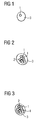
- Fig. 1-3 explain the mode of action of the invention in the scale of droplet formation.
- Fig. 1 shows the simplest case.
- the material of the condensation nuclei here as well as titanium dioxide below, has a certain affinity for water, as shown by a low contact angle. If a particle 1 is present in a supersaturated water vapor stream, water molecules accumulate and a droplet 3 forms. If the particles are very small, for example nanoparticles, a large amount of water vapor can condense with a low material consumption.
- agglomerated particles 1 for the condensation cf. Fig. 2
- these indicated pore structure 2 can force the condensation of water to a droplet 3 faster and by capillary forces at a lower supersaturation. In extreme cases, even some of the vapor condenses before reaching supersaturation.
- the modifying substance can be derived from the precursor which is dusted into the vapor stream to form the particles 1, for example form the solvent for the precursor.
- a fluorine compound which prevents agglomeration can be added to the precursor or the precursor solution.
- Other additives which affect the size and agglomeration as well as the organic layer 4 can also be used.
- insoluble titanium dioxide nanoparticles serving as condensation nuclei are to be introduced into a vapor stream. It is intended to use titanium (IV) -butoxide as a precursor, which is finely atomized into the vapor stream in order there to form the insoluble nanoparticles with the already existing water in the context of a chemical reaction, here a hydrolysis.
- a chemical reaction here a hydrolysis.
- the reaction equation of the associated hydrolysis has already been laid down in the general description.
- the titanium (IV) butoxide is liquid and is diluted with organic solvents, in which example a 1% solution in alcohol is used. In this way, the properties of the precursor can be adjusted.
- the reaction to the particles 1 thus takes place in situ in the vapor stream
- Fig. 4 now shows a first embodiment of an ultrasonic piezo-atomizer 5, which can be used for fine atomization of the diluted with alcohol precursor.
- the atomizer 5 is formed here essentially by the oscillating in operation, substantially frusto-conical high-frequency electrode 6, which has a sputtering surface 7.
- the ground electrode 8 connects. Both electrodes are correspondingly connected to a high frequency power supply indicated at 9.
- a supply line 10 is guided for the precursor, which is designed here as a capillary 11.
- the supply line 10 is part of a supply device 13, which in addition to a reservoir 14 for the precursor comprises a pump 15 which continuously promotes the precursor through the capillary 11 to the sputtering surface 7, where the precursor distributed and by the high-frequency vibrations of the Atomizing surface 7 is sprayed upward in the direction of the vapor stream (arrow 16).
- the electrodes 6, 8 and the capillary 11 can each be made of metal.
- the ultrasonic piezo atomizer shown here can for example have a diameter of about 1 cm, although of course other sizes are conceivable.
- a plurality of such ultrasonic piezoelectric atomizers 5 may be provided, although the now with reference to Fig. 5 described variant of an ultrasonic piezo-atomizer 17 can be used.
- the in Fig. 5 illustrated ultrasonic piezoelectric sprayer 17 an elongated shape with turn a high-frequency electrode 18 and a ground electrode 19, wherein the ground electrode 19 forms the actual vibrating body with the elongated sputtering surface 20 here.
- the arrows 21 indicate the direction of flow of the vapor stream via the sputtering surface 20.
- the supply line 22 of the supply device 23 branches in this case in nine capillaries 24, the openings 25 are arranged centrally on the sputtering surface 20 at equidistant intervals in the longitudinal direction. Through all these openings 25 precursors are continuously applied to the sputtering surface 20 by means of a pump device indicated at 26. Ultimately, it is a stationary process in which precursors are continuously atomized and introduced into the vapor stream. If solids, for example particles 1, form on the sputtering surface 20, they are simply repelled by the vibrations and transferred into the vapor stream. Incidentally, this also applies to the piezo atomizer 5.
- a control unit 27 which ensures the most uniform atomization possible. Essentially, two adjacent control processes are used for this purpose.
- the adjustable high-frequency supply 28 is regulated. This provides a high-frequency current of a certain frequency. This should, in order to achieve the optimum sputtering effect, the resonant frequency of the ground electrode 19. However, this resonant frequency is dependent on the amount of precursor that is currently on the sputtering surface 20. Via the control unit 27 it is now possible, first continuously, arrows 29 and 30, to measure the supply voltage and the supply current. From these results the impedance, which is minimal at the resonant frequency, thus by the control unit 27 by appropriate Control of the radio frequency supply 28 is minimized by varying the frequency. Consequently, a current resonance frequency is always known, but also contains a statement about how much precursor is currently located on the sputtering surface 20.
- the pump device 26 can thus be controlled in a second step, arrow 31, in such a way that the atomization of precursor into the vapor stream is kept as constant as possible. If, for example, too much precursor is contained on the atomizing surface 20, the supply via the supply line 22 can be throttled for a short time and vice versa.
- a self-regulating system which can be used for uniform atomization of precursor into the vapor stream.
- the precursor then reacts in the said hydrolysis reaction to give titanium dioxide, which contains the nanoparticles 1 serving as condensation nuclei, cf. Fig. 1-3 , forms.
- Fig. 6 finally shows relevant parts of a steam turbine 32 according to the invention in a schematic representation.
- a steam supply line 33 with a main steam channel 35 narrowing before entry into the blade housing 34 the steam is supplied to the turbine blades 37 arranged on the driven shaft 36, a symmetrical structure being shown here.
- a portion of the vapor stream is fed via a feed line 38 into a so-called bubble 39, in which the indicated at 17 atomizer is arranged.
- the enriched with the precursor or already by hydrolysis nanoparticles 1 steam is fed through a derivative 40 back to the main steam passage 35.
- the fluid dynamics of the steam supply line 33 has been taken into account so that as optimal as possible mixing and thus a distribution of nanoparticles 1 over the entire vapor stream is achieved.
- the feed line 38 for a part of the vapor stream to load an inert gas with the precursor and to feed it into the main steam channel 35.
Landscapes
- Engineering & Computer Science (AREA)
- Mechanical Engineering (AREA)
- General Engineering & Computer Science (AREA)
- Chemical & Material Sciences (AREA)
- Combustion & Propulsion (AREA)
- Special Spraying Apparatus (AREA)
- Turbine Rotor Nozzle Sealing (AREA)
- Organic Low-Molecular-Weight Compounds And Preparation Thereof (AREA)
- Catalysts (AREA)
Description
- Die Erfindung betrifft ein Verfahren zum Betrieb einer Dampfturbine gemäß Anspruch 1, eine zugehörige Dampfturbine umfassend durch Dampf betriebene Turbinenschaufeln und eine Dampfzuleitung zu den Turbinenschaufeln, sowie einen Zerstäuber zum Einsatz in der Dampfturbine gemäß Anspruch 4.
- Dampfturbinen sind im Stand der Technik grundsätzlich bekannt und bilden meist Bestandteil eines Kreisprozesses, der auch Dampfturbinenprozess genannt wird. Dabei wird Wasser in einem Dampferzeuger erhitzt und strömt als Dampf in die Dampfturbine. In der Dampfturbine entspannt sich der Dampf und treibt so die Turbine und einen angeschlossenen Generator an. Im Kondensator wird der Wasserdampf dann gekühlt und wieder zu Wasser kondensiert. Beispielsweise mittels einer Pumpe wird das Kondenswasser wieder auf den Druck im Dampferzeuger gebracht und dorthin gepumpt.
- Verschiedenste Ansätze wurden und werden verfolgt, um den Wirkungsgrad von Dampfturbinen zu steigern. Neben mechanischen Maßnahmen wurde jedoch auch vorgeschlagen, Chemikalien in den Dampfstrom zuzugeben, um so einen höheren Turbinenwirkungsgrad zu erzielen. Die grundlegende Idee ist es, die Kondensation des Wasserdampfes zu unterstützen und somit einer Übersättigung entgegenzuwirken. Damit soll insbesondere auch einer Erosion entgegengewirkt werden, die durch entstandene größere Tröpfchen (primär oder sekundär) an den Turbinenschaufeln auftreten kann.
- Bei der Zugabe von Chemikalien sind unterschiedliche Ansatzmöglichkeiten bekannt, um die Kondensation zu unterstützen und somit den Wirkungsgrad von Dampfturbinen bei gleichzeitiger Erosionsvermeidung zu steigern. So wurde vorgeschlagen, als zusätzliche Chemikalie Tenside in den Dampfstrom einzubringen, die die Oberflächenspannung von Tröpfchen erniedrigen, was eine Kondensation begünstigt. In einer anderen Variante wurde vorgeschlagen, lösliche Substanzen, beispielsweise Salze, zuzugeben, um den Dampfdruck der Tröpfchen zu erniedrigen. Dabei tritt allerdings der Nachteil auf, dass durch die Zugabe von wasserlöslichen ionischen Substanzen eine Korrosion der Anlage begünstigt wird, so dass dieser Ansatz kaum eine Anwendung innerhalb von Dampfturbinen finden wird.
- Der Erfindung liegt daher die Aufgabe zugrunde, ein Verfahren zum Betrieb einer Dampfturbine sowie eine zugehörige Dampfturbine anzugeben, bei denen die Kondensationseigenschaften möglichst ohne schädigende Einflüsse auf die Dampfturbine zur Erreichung eines höheren Wirkungsgrades verbessert werden.
- Zur Lösung dieser Aufgabe ist erfindungsgemäß ein Verfahren zum Betrieb einer Dampfturbine vorgesehen, bei dem der in die Dampfturbine einzuleitende Dampf mit unlöslichen, Kondensationskeime bildenden Partikeln versetzt wird.
- Die Idee der vorliegenden Erfindung ist es folglich, wasserunlösliche Partikel zuzugeben, die als Kondensationskeime dienen können. Die Voraussetzung dafür ist, dass die Kondensationskeime, also die Partikel, einen niedrigen Kontaktwinkel zu Wasser aufweisen. Ein aus dem Stand der Technik bekanntes Beispiel für Kondensationskeime sind Silberjodid-Partikel (AgI). Diese Substanz findet derzeit Anwendung, wenn ein Abregnen von Wolken in der Atmosphäre erzwungen werden soll. Erfindungsgemäß bevorzugt ist es jedoch, dass die Partikel aus Titandioxid bestehen. Aus Titandioxid als Material für die Partikel können ebenso sehr kleine, unlösliche Partikel mit niedrigem Kontaktwinkel zu Wasser hergestellt werden.
- Zweckmäßig ist die Verwendung möglichst kleiner Partikel, um bei einem geringen Materialverbrauch eine maximale Anzahl von Kondensationskeimen zu generieren und die entstehenden Tröpfchen in ihrer Größe zu begrenzen. Beispielsweise können in erster Näherung sphärische Partikel verwendet werden, deren Größe im Bereich von 2 - 250 nm liegt. Insbesondere werden Nanopartikel verwendet, deren Größe mithin von 1 - 100 nm reicht. Allerdings kann auch vorgesehen sein, eine Agglomeration von in erster Näherung sphärischen Partikeln zu größeren Partikeln zu erlauben.
- Die wasserunlöslichen Partikel werden folglich vor dem Erreichen der Turbinenschaufeln in den Dampfstrom eingebracht. Da die Partikel nicht in Wasser löslich sind, wird eine Korrosion vermieden. Weiterhin werden sehr kleine Partikel, insbesondere Nanopartikel, verwendet, da hiermit Material eingespart werden kann und auch eine Erosion durch Kollision der Partikel oder Tröpfchen mit den Schaufeln verringert werden kann.
- Die Partikel, insbesondere die Nanopartikel, dienen dabei als Kondensationskeime, so dass einer Übersättigung entgegengewirkt wird. Im Idealfall kann diese sogar vermieden werden. Es ergibt sich eine zeitnahe Kondensation mit vielen kleinen Tröpfchen, insbesondere, wenn sehr kleine Partikel verwendet werden. Auf diese Weise wird schließlich der Wirkungsgrad der Dampfturbine erhöht und es tritt weniger Tropfenschlagerosion auf.
- Die Partikel wirken dabei in den letzten Stufen der Dampfturbine, und zwar hauptsächlich in der Region, in der eine Übersättigung eintreten kann. Dabei sollten die Partikel möglichst so in den Dampfstrom eingebracht werden, dass sie über den gesamten Querschnitt des Dampfstroms innerhalb der Dampfturbine verteilt vorliegen. Auf diese Weise wirken die positiven Eigenschaften der vorliegenden Erfindung auf den gesamten Dampfstrom.
- Es hat sich im Rahmen der vorliegenden Erfindung gezeigt, dass die Bereitstellung von unlöslichen Partikeln in einem Dampfstrom praktische Schwierigkeiten mit sich bringen kann. Denn in fester Form lassen sich Partikel, insbesondere Nanopartikel, zum einen nur schlecht transportieren, zum anderen sind makroskopische Methoden der Feststoffförderung aus der Verfahrenstechnik nur schwer anwendbar, da eine übermäßige Agglomeration zu übergroßen Partikeln auftreten kann. Daher kann beim erfindungsgemäßen Verfahren mit besonderem Vorteil vorgesehen sein, dass ein Präkursor des Materials, aus denen die Partikel bestehen, in den Dampf insbesondere feinzerstäubt eingebracht wird, wo in einer Hydrolysereaktion das Material und die Partikel entstehen. Es wird daher vorgeschlagen, von einem flüssigen Präkursor auszugehen, der dann in den Dampfstrom hinein fein zerstäubt wird, um dort mit dem Wasser im Rahmen einer chemischen Reaktion die unlöslichen Partikel, insbesondere Nanopartikel, zu bilden. Sollen beispielsweise die Partikel aus Titandioxid (TiO2) bestehen, so kann als Präkursor vorteilhafterweise Titan-(IV)-Butoxid (Ti(OC4H9)4) verwendet werden. Die Reaktionsgleichung der Hydrolyse lautet dann:
Ti (OC4H9)4 + 2 H20 → TiO2 + 4 HOC4H9.
- Auf diese Weise können mit der vorliegenden Erfindung die Partikel durch die Hydrolyse des flüssig vorliegenden Präkursors in situ erzeugt werden. Das hat den Vorteil, dass eine technisch aufwendige Förderung bzw. Dosierung von Feststoffen vermieden wird und, worauf im Folgenden noch näher eingegangen werden wird, Eigenschaften der resultierenden Partikel (Größe, Form, Agglomeration, Oberflächenmodifizierungen) durch die Zusammensetzung der Präkursorlösung und die Einstellungen der Zerstäubung beeinflusst werden können.
- Dabei kann weiter vorgesehen sein, dass der Präkursor insbesondere mit Alkohol verdünnt wird. Es können folglich organische, nicht-wässrige Lösungsmittel verwendet werden, insbesondere Alkohol, um den Präkursor zu verdünnen. Auf diese Weise lassen sich die physikalischen Eigenschaften der Lösung an die gegebenen Anforderungen anpassen. Insbesondere lassen sich die Eigenschaften der Kondensationskeime, also der Partikel, beeinflussen, beispielsweise ihre Größe und/oder die Agglomeration. Bei einer bestimmten Art von Lösungsmitteln kann auch erreicht werden, dass die Partikel mit einem organischen Überzug versehen werden, der beispielsweise die Eigenschaften als Kondensationskeim verbessern kann und/oder die Agglomeration vermeiden kann. Selbstverständlich können auch andere oder weitere Zusätze zu verschiedenen Zwecken dem Präkursor zugefügt werden, insbesondere, um eine organische Schicht auf den Partikeln zu erzeugen. So kann vorgesehen sein, dass Fluorverbindungen hinzugegeben werden, um die Agglomeration von Partikeln zu verringern.
- Der Hauptvorteil des beschriebenen flüssigen Präkursors ist die Möglichkeit, ihn pumpen und feinzerstäuben zu können. Prinzipiell lassen sich herkömmliche Pumpen zur Zudosierung verwenden, wobei jedoch in der Hydrolyseempfindlichkeit des Präkursors und der damit einhergehenden Feststoffbildung besondere Maßnahmen nötig sind, um ein Verstopfen der Zuleitungen zu vermeiden. Mithin kann es bei der Verwendung konventioneller Einspritzdüsen, welche nichtsdestotrotz durchaus verwendet werden können, zu Nachteilen kommen, wenn beispielsweise der Querschnitt der Einspritzdüsen durch gebildete Feststoffe blockiert werden kann. Dabei kann vorgesehen sein, eine Hochdruckleistungspumpe zu verwenden, um in der Einspritzdüse auftretende Feststoffe im Zweifel durch große Kräfte aus der Einspritzdüse zu entfernen.
- In besonders zweckmäßiger Ausgestaltung der vorliegenden Erfindung kann jedoch vorgesehen sein, dass der Präkursor mit einem Ultraschall-Piezozerstäuber zerstäubt wird. Ein solcher Zerstäuber weist idealerweise eine Zerstäubungsfläche auf, auf die die Zuleitung für den Präkursor mündet. Wird nun der Piezozerstäuber bei seiner Eigenfrequenz betrieben, resultiert hieraus eine Vibration dieser Zerstäubungsfläche und der Präkursor wird durch die Schwingung des Zerstäubers in den Dampfstrom eingebracht. Da die eigentliche Aufwirbelung auf der Zerstäubungsfläche stattfindet, besteht durch einen solchen Ultraschall-Piezozerstäuber der Vorteil, dass er ohne enge Zuleitungen auskommt und somit die Gefahr einer Verstopfung der Zuleitung reduziert ist. Zudem hat er selbstreinigende Eigenschaften, das bedeutet, wenn sich auf der Zerstäubungsfläche ungewollt ein Feststoff bilden sollte, wird dieser durch die Schwingungen des Zerstäubers hinfort geschleudert und mit dem Dampfstrom entfernt. Wird der Präkursor beispielsweise über eine Pumpe zugeführt, so kann über die Betriebsparameter der Pumpe eine hochgenaue Dosierung erfolgen.
- Zweckmäßigerweise wird der Präkursor kontinuierlich durch eine Zuleitung unmittelbar auf die Zerstäubungsfläche dosiert. Das bedeutet, die Zuleitung für den Präkursor endet unmittelbar auf der Zerstäubungsfläche des Ultraschall-Piezozerstäubers, wobei der Präkursor durch diese kontinuierlich zugeführt werden kann. Auf diese Weise entsteht der Vorteil, dass der Prozess unter stationären Bedingungen gefahren werden kann, während beispielsweise bei einer tropfenweisen Dosierung das System periodisch zwischen Präkursorüberschuss (frischer Tropfen) und Präkursormangel (Tropfen ist quasi vollständig zerstäubt) wechseln würde.
- Vorzugsweise sollten die als Kondensationskeime dienenden Partikel jedoch nicht nur zeitlich gleichmäßig erzeugt werden, sondern auch räumlich. Am effizientesten ist das erfindurigsgemäße Verfahren einsetzbar, wenn der gesamte Dampfstrom erfasst wird. Die genaue Vorgehensweise hängt dabei von der Fluiddynamik innerhalb einer Dampfturbine ab, worauf bezüglich der erfindungsgemäßen Dampfturbine noch näher eingegangen werden wird.
- Wird ein Ultraschall-Piezozerstäuber verwendet, so kann dessen Eigenschaft, dass die elektrische Leistungsaufnahme und deren Umsetzung in hochfrequente, mechanische Schwingung nur dann optimal ist, wenn das System in Resonanz betrieben wird, vorteilhaft auch zur Regelung verwendet werden. Dabei kann beispielsweise vorgesehen sein, dass eine Steuereinheit die Versorgungsspannung und/oder den Versorgungsstrom, die von einer Hochfrequenz-Versorgung an den Piezozerstäuber abgegeben werden, in Abhängigkeit von deren Frequenz misst. Bei der Resonanzfrequenz ist die Impedanz minimal, das bedeutet, es fließt der größte Strom bei konstanter Spannung. Auf diese Weise kann also durch Variation der Frequenz und Minimierung der Impedanz die Resonanzfrequenz aufgefunden werden. In einem weiteren Schritt kann jedoch auch der Effekt genutzt werden, dass die Resonanzfrequenz selber nun wieder unter anderem von der Masse des schwingenden Systems abhängt, mithin auch von der Menge des auf der Zerstäubungsfläche vorhandenen Präkursors.
- Wurde also, wie beschrieben, durch Messung von Spannung und Strom und entsprechende Minimierung der Impedanz die aktuelle Resonanzfrequenz des Piezozerstäubers durch Regelung aufgefunden, so kann aus dieser Resonanzfrequenz auf den Beladungszustand des Piezozerstäubers mit Präkursor bzw. Präkursorlösung geschlossen werden, so dass es möglich ist, den Massenstrom des Präkursors dem jeweiligen Betriebszustand des Piezozerstäubers anzupassen. Die Steuereinheit steuert also eine Zuleitungsvorrichtung zur Zuleitung des Präkursors auf die Zerstäubungsfläche abhängig von der Resonanzfrequenz so an, dass eine weitere zeitliche Kontinuität erreicht wird und vermieden wird, dass beim Zerstäuben zu große Tropfen entstehen, die zu zu große Partikeln führen könnten.
- Neben dem Verfahren betrifft die Erfindung auch eine Dampfturbine, umfassend durch Dampf betriebene Turbinenschaufeln und eine Dampfzuleitung zu den Turbinenschaufeln, welche sich dadurch auszeichnet, dass an der Dampfzuleitung ein Mittel zum Versetzen des Dampfes mit unlöslichen, Kondensationskeime bildenden Partikeln vorgesehen ist. Sämtliche Ausführungen bezüglich des erfindungsgemäßen Verfahrens lassen sich selbstverständlich analog auf die erfindungsgemäße Dampfturbine übertragen.
- So kann insbesondere vorgesehen sein, dass die Partikel aus Titandioxid bestehen und als Nanopartikel und/oder mit einer Größe im Bereich von 2 - 250 nm ausgebildet sind.
- In weiterer Ausgestaltung der Dampfturbine kann diese wenigstens einen Zerstäuber für einen Präkursor des Materials der Partikel umfassen, welcher Präkursor hydrolytisch zu dem Material reagiert. Vorzugsweise handelt es sich, wie bereits beschrieben, bei dem Zerstäuber um einen Ultraschall-Piezozerstäuber, so dass die oben bereits dargestellten Vorteile erreicht werden können. Der Zerstäuber kann eine Zuleitungsvorrichtung mit einer Zuleitung für den Präkursor umfassen, welche Zuleitung auf einer Zerstäubungsfläche des Ultraschall-Piezozerstäubers endet, welche Zuleitungsvorrichtung zum kontinuierlichen Zuführen von Präkursor auf die Zerstäubungsfläche ausgebildet ist. Es sei an dieser Stelle angemerkt, dass es grundsätzlich denkbar ist, mehrere derartige Zerstäuber vorzusehen, in einer vorteilhaften weiteren Ausgestaltung jedoch auch ein großflächiger Zerstäuber mit einer großflächigen Zerstäubungsfläche vorgesehen werden kann, der mehrere Öffnungen von Zuleitungen auf einer oder mehreren Zerstäubungsflächen aufweist. Auf diese Weise kann sichergestellt werden, dass hinreichend viel Präkursor in den Dampfstrom gelangt, wo der Präkursor im Rahmen der Hydrolysereaktion mit dem enthaltenen Wasser selbst reagieren kann, um die Partikel zu bilden.
- Wie bereits erwähnt, ermöglicht die Verwendung des Ultraschall-Piezozerstäubers auch eine vorteilhafte Regelung des gesamten Einstäubungssystems. Zunächst kann in einem ersten Schritt vorgesehen sein, dass eine Steuereinheit zur Regelung der Hochfrequenzversorgung des Zerstäubers, insbesondere der Frequenz, in Abhängigkeit des Versorgungsstroms und/oder der Versorgungsspannung vorgesehen ist. Wie bereits erläutert, wird auf eine möglichst niedrige Impedanz, also auf die Resonanzfrequenz hin, geregelt, indem der Versorgungsstrom und/ oder die Versorgungsspannung gemessen werden. Ergebnis ist immer eine aktuelle Resonanzfrequenz, bei der der Ultraschall-Piezozerstäuber betrieben wird. In Weiterbildung der Erfindung kann die Steuereinheit zusätzlich zur Regelung des Massenstroms des Präkursors in Abhängigkeit einer durch die Steuereinheit ermittelten aktuellen Resonanzfrequenz des Zerstäubers ausgebildet sein. Denn die aktuelle Resonanzfrequenz beschreibt mit, wie viel Präkursor gerade an der Zerstäubungsfläche anliegt, so dass zu große oder zu kleine Mengen des Präkursors detektiert werden können und nachgeregelt werden kann.
- Wie bereits erwähnt, ist es denkbar, einen Zerstäuber unmittelbar in einem Hauptdampfkanal der Dampfzuleitung zu den Turbinenschaufeln vorzusehen. Beispielsweise kann ein solcher Zerstäuber länglich sein und bei einer Ausbildung als Ultraschall-Piezozerstäuber mehrere Öffnungen auf der länglichen Zerstäubungsfläche aufweisen, um so eine gleichmäßige Verteilung in dem Dampf zu erzielen. Die Längsrichtung entspricht dabei der Richtung des Hauptdampfkanals, so dass der Präkursor letztlich transversal eingestäubt wird.
- Zweckmäßigerweise kann jedoch auch vorgesehen sein, dass die Dampfturbine eine Blase mit dem Zerstäuber umfasst, die eine Zuleitung für einen Teil des Dampfstroms und/oder einen inerten Gasstrom und eine zum Hauptdampfkanal führende Ableitung aufweist. Eine derartige Blase, die mithin mit dem Hauptdampfkanal verbunden ist, dient also dazu, den Präkursor in zumindest einen Teil des Dampfstroms oder einen inerten Gasstrom einzubringen. Ein derartiger inerter Gasstrom, der beispielsweise von einer weiteren Gasquelle ausgehen kann, dient dann lediglich zum Zuführen des Präkursors durch die Ableitung in den Hauptdampfkanal. Es kann jedoch auch vorgesehen sein, dass ein Teil des Dampfstroms beispielsweise vom Hauptdampfkanal abgeleitet wird, durch die Blase mit dem Zerstäuber geführt wird und dann wieder in den Hauptdampfkanal eingespeist wird. Die Blase kann dabei insbesondere in einem verengten Bereich vor dem Eintritt in das Schaufelgehäuse vorgesehen werden. Grundsätzlich ist jedoch bei der Positionierung die Fluiddynamik innerhalb der Dampfturbine zu berücksichtigen. Insbesondere sollte eine möglichst vollständige Durchmischung des durch die Ableitung dem Dampfstrom wieder zugeführten Teildampfstroms oder inerten Gasstroms mit dem Dampfstrom möglich sein.
- Schließlich betrifft die Erfindung noch einen Zerstäuber für einen Präkursor, der in der erfindungsgemäßen Dampfturbine, wie sie soeben beschrieben wurde, eingesetzt werden kann. Sämtliche bezüglich des Zerstäubers getätigten Ausführungen sind analog auf den erfindungsgemäßen Zerstäuber anzuwenden, so dass dieser insbesondere als ein Ultraschall-Piezozerstäuber mit einer Zerstäuberfläche ausgebildet sein kann, in die eine Zuleitung für den Präkursor mündet.
- Weitere Vorteile und Einzelheiten der vorliegenden Erfindung ergeben sich aus den im Folgenden beschriebenen Ausführungsbeispielen sowie anhand der Zeichnung. Dabei zeigen:
- Fig. 1 - 3
- eine Illustration zur Wirkungsweise von unlöslichen, als Kondensationskeime wirkenden Partikeln,
- Fig. 4
- eine Detailansicht eines erfindungsgemäßen Zerstäubers,
- Fig. 5
- ein weiterer erfindungsgemäßer Zerstäuber, und
- Fig. 6
- eine erfindungsgemäße Gasturbine.
- Die
Fig. 1 - 3 erläutern das Wirkprinzip der Erfindung im Maßstab der Tröpfchenbildung.Fig. 1 zeigt den einfachsten Fall. Dabei liegen in erster Näherung sphärische, unlösliche, Kondensationskeime bildende Partikel 1 vor. Das Material der Kondensationskeime, hier wie auch im Folgenden Titandioxid, hat eine gewisse Affinität zu Wasser, was sich an einem niedrigen Kontaktwinkel zeigt. Wenn ein Partikel 1 in einem übersättigten Wasserdampfstrom vorliegt, lagern sich Wassermoleküle an und es entsteht ein Tröpfchen 3. Sind die Partikel sehr klein, beispielsweise Nanopartikel, lässt sich auf diese Weise bei einem niedrigen Materialverbrauch eine große Menge an Wasserdampf kondensieren. - In einigen Fällen kann es zweckmäßig sein, agglomerierte Partikel 1 für die Kondensation bereitzustellen, vgl.
Fig. 2 , die dann eine angedeutete Porenstruktur 2 aufweisen. Diese angedeutete Porenstruktur 2 kann die Kondensation von Wasser zu einem Tröpfchen 3 schneller und durch Kapillarkräfte bei einer niedrigeren Übersättigung erzwingen. Im Extremfall kondensiert sogar ein gewisser Teil des Dampfes noch vor dem Erreichen einer Übersättigung aus. - Als dritte Variante zeigt
Fig. 3 schließlich die Möglichkeit, die Oberfläche der Partikel 1 bzw. der agglomerierten Partikel 1 in ihren Eigenschaften durch eine organische Schicht 4 zu modifizieren. Dabei kann die modifizierende Substanz dem Präkursor, der zur Bildung der Partikel 1 in den Dampfstrom eingestäubt wird, entstammen, beispielsweise das Lösungsmittel für den Präkursor bilden. Aber auch andere Zusätze sind denkbar. Beispielsweise kann dem Präkursor bzw. der Präkursorlösung eine Fluorverbindung zugesetzt werden, die die Agglomeration verhindert. Auch andere Zusätze, die Einfluss auf die Größe und Agglomeration sowie die organische Schicht 4 haben, können verwendet werden. - Im vorliegenden Beispiel sollen unlösliche, als Kondensationskeime dienende Nanopartikel aus Titandioxid in einen Dampfstrom eingebracht werden. Dafür ist vorgesehen, Titan-(IV)-Butoxid als Präkursor zu verwenden, der in den Dampfstrom hinein fein zerstäubt wird, um dort mit dem ohnehin vorhandenen Wasser im Rahmen einer chemischen Reaktion, hier eine Hydrolyse, die unlöslichen Nanopartikel zu bilden. Die Reaktionsgleichung der zugehörigen Hydrolyse wurde in der allgemeinen Beschreibung bereits niedergelegt.
- Das Titan-(IV)-Butoxid ist flüssig und wird mit organischen Lösemitteln verdünnt, wobei in diesem Beispiel eine 1 %ige Lösung in Alkohol verwendet wird. Auf diese Weise können die Eigenschaften des Präkursors angepasst werden. Die Reaktion zu den Partikeln 1 findet also in situ im Dampfstrom statt
-
Fig. 4 zeigt nun ein erstes Ausführungsbeispiel eines Ultraschall-Piezozerstäubers 5, der zum feinen Zerstäuben des mit Alkohol verdünnten Präkursors verwendet werden kann. Der Zerstäuber 5 wird hier im Wesentlichen gebildet durch die im Betrieb schwingende, im Wesentlichen kegelstumpfförmig ausgebildete Hochfrequenz-Elektrode 6, die eine Zerstäubungsfläche 7 aufweist. Am unteren Ende der Hochfrequenz-Elektrode 6 schließt sich die Masseelektrode 8 an. Beide Elektroden sind entsprechend mit einer bei 9 angedeuteten Hochfrequenzstromversorgung verbunden. - Zentral durch die Elektroden 6, 8 ist eine Zuleitung 10 für den Präkursor geführt, die hier als Kapillare 11 ausgebildet ist. Die Kapillare 11, deren Durchmesser größer gewählt ist als der üblicher Zuleitungen für einen Zerstäuber, um das Risiko einer Verstopfung zu minimieren, endet inmitten der Zerstäubungsfläche 7, vgl. Öffnung 12. Die Zuleitung 10 ist Teil einer Zuleitungsvorrichtung 13, welche neben einem Reservoir 14 für den Präkursor eine Pumpe 15 umfasst, die kontinuierlich den Präkursor durch die Kapillare 11 auf die Zerstäubungsfläche 7 fördert, wo sich der Präkursor verteilt und durch die hochfrequenten Schwingungen der Zerstäubungsfläche 7 nach oben in Richtung des Dampfstroms (Pfeil 16) zerstäubt wird.
- Es sei bereits an dieser Stelle angemerkt, dass auch eine Steuereinheit zur Regelung bei dem Zerstäuber 5 vorgesehen sein kann, wie sie später mit Bezug auf
Fig. 5 noch näher erläutert werden wird. - Die Elektroden 6, 8 sowie die Kapillare 11 können dabei jeweils aus Metall gefertigt sein. Der hier dargestellte Ultraschall-Piezozerstäuber kann beispielsweise einen Durchmesser von etwa 1 cm aufweisen, wobei selbstverständlich auch andere Größen denkbar sind. Für eine übliche Dampfturbine können eine Mehrzahl solcher Ultraschall-Piezozerstäuber 5 vorgesehen sein, wobei allerdings auch die nun mit Bezug auf
Fig. 5 beschriebene Variante eines Ultraschall-Piezozerstäubers 17 verwendet werden kann. - Ersichtlich weist der in
Fig. 5 dargestellte Ultraschall-Piezozerstäuber 17 eine längliche Form mit wiederum einer Hochfrequenz-Elektrode 18 und einer Masseelektrode 19 auf, wobei die Masseelektrode 19 hier den eigentlichen Schwingkörper mit der länglichen Zerstäubungsfläche 20 bildet. Die Pfeile 21 deuten die Flussrichtung des Dampfstroms über die Zerstäubungsfläche 20 an. - Die Zuleitung 22 der Zuleitungsvorrichtung 23 zweigt sich dabei auf in in diesem Ausführungsbeispiel neun Kapillaren 24, deren Öffnungen 25 mittig auf der Zerstäubungsfläche 20 in äquidistanten Abständen in Längsrichtung angeordnet sind. Durch alle diese Öffnungen 25 wird kontinuierlich mittels einer bei 26 angedeuteten Pumpvorrichtung Präkursor auf die Zerstäubungsfläche 20 aufgebracht. Es handelt sich also letztlich um einen stationären Prozess, in dem kontinuierlich Präkursor zerstäubt und in den Dampfstrom eingebracht wird. Sollten sich Feststoffe, beispielsweise Partikel 1, auf der Zerstäubungsfläche 20 bilden, so werden diese durch die Schwingungen einfach abgestoßen und in den Dampfstrom überführt. Dies gilt im Übrigen auch für den Piezozerstäuber 5.
- Gezeigt ist in
Fig. 5 ferner eine Steuereinheit 27, die für einen möglichst gleichmäßigen Zerstäubungsvorgang sorgt. Dazu dienen im Wesentlichen zwei aneinandergekoppelte Regelprozesse. - Zum einen wird die einstellbare Hochfrequenzversorgung 28 geregelt. Diese stellt einen hochfrequenten Strom einer bestimmten Frequenz zur Verfügung. Diese sollte, um die optimale Zerstäubungswirkung zu erzielen, die Resonanzfrequenz der Masseelektrode 19 sein. Diese Resonanzfrequenz ist jedoch abhängig von der Menge an Präkursor, die sich gerade auf der Zerstäubungsfläche 20 befindet. Über die Steuereinheit 27 ist es nun möglich, zunächst kontinuierlich, Pfeile 29 und 30, die Versorgungsspannung und den Versorgungsstrom zu messen. Aus diesen ergibt sich die Impedanz, die bei der Resonanzfrequenz minimal ist, mithin von der Steuereinheit 27 durch entsprechende Ansteuerung der Hochfrequenzversorgung 28 durch Variation der Frequenz minimiert wird. Mithin ist immer eine aktuelle Resonanzfrequenz bekannt, die aber auch eine Aussage darüber enthält, wie viel Präkursor sich gerade auf der Zerstäubungsfläche 20 befindet.
- Abhängig von der Resonanzfrequenz kann folglich in einem zweiten Schritt, Pfeil 31, die Pumpvorrichtung 26 so angesteuert werden, dass die Einstäubung von Präkursor in den Dampfstrom möglichst konstant gehalten wird. Ist beispielsweise zuviel Präkursor auf der Zerstäubungsfläche 20 enthalten, kann der Nachschub über die Zuleitung 22 kurzzeitig gedrosselt werden und umgekehrt.
- Auf diese Weise ist ein selbstregelndes System gegeben, welches für eine gleichmäßige Einstäubung von Präkursor in den Dampfstrom verwendet werden kann. In dem Dampfstrom reagiert der Präkursor dann in der genannten Hydrolysereaktion zu Titandioxid, welches die als Kondensationskeime dienenden Nanopartikel 1, vgl.
Fig. 1 -3 , bildet. -
Fig. 6 zeigt schließlich relevante Teile einer erfindungsgemäßen Dampfturbine 32 in einer Prinzipdarstellung. Über eine Dampfzuleitung 33 mit einem sich vor Eintritt in das Schaufelgehäuse 34 verengenden Hauptdampfkanal 35 wird der Dampf den auf der anzutreibenden Welle 36 angeordneten Turbinenschaufeln 37 zugeführt, wobei hier ein symmetrischer Aufbau gezeigt ist. - Ein Teil des Dampfstroms wird über eine Zuleitung 38 in eine sogenannte Blase 39 geführt, in der der bei 17 angedeutete Zerstäuber angeordnet ist. Der mit dem Präkursor bzw. schon durch Hydrolyse entstandenen Nanopartikeln 1 angereicherte Dampf wird durch eine Ableitung 40 wieder dem Hauptdampfkanal 35 zugeführt. Bei dieser Konstruktion ist die Fluiddynamik der Dampfzuleitung 33 so berücksichtigt worden, dass möglichst eine optimale Durchmischung und somit eine Verteilung von Nanopartikeln 1 über den gesamten Dampfstrom erreicht wird.
- Es kann anstatt der Zuleitung 38 für einen Teil des Dampfstroms im Übrigen auch vorgesehen sein, ein inertes Gas mit dem Präkursor zu beladen und in den Hauptdampfkanal 35 einzuspeisen.
- Es können selbstverständlich auch mehrere Zerstäuber 17 vorgesehen sein, aber auch mehrere der Zerstäuber 5 statt den Zerstäubern 17.
- Schließlich sei noch angemerkt, dass es grundsätzlich bei einer geeigneten Fluiddynamik selbstverständlich auch denkbar ist, Zerstäuber 5 oder 17 unmittelbar im Hauptdampfkanal 35 anzuordnen, um so den Präkursor fein in den Wasserdampf zu zerstäuben, dass er aufgrund der Hydrolysereaktion gleichmäßig mit Nanopartikeln 1 versetzt wird.
Claims (8)
- Verfahren zum Betrieb einer Dampfturbine, wobei der in die Dampfturbine einzuleitende Dampf mit unlöslichen, Kondensationskeime bildenden Partikeln versetzt wird, und wobei ein Präkursor des Materials, aus dem die Partikel bestehen, in den Dampf insbesondere fein zerstäubt eingebracht wird, wo in einer Hydrolysereaktion das Material und die Partikel entstehen, dadurch gekennzeichnet, dass der Präkursor mit einem Ultraschall-Piezozerstäuber zerstäubt wird.
- Verfahren nach Anspruch 1, dadurch gekennzeichnet, dass die Partikel aus Titandioxid bestehen.
- Verfahren nach Anspruch 1 oder 2, dadurch gekennzeichnet, dass der Präkursor insbesondere mit Alkohol verdünnt wird.
- Dampfturbine (32), umfassend durch Dampf betriebene Turbinenschaufeln (37) und eine Dampfzuleitung (33) zu den Turbinenschaufeln (37), wobei an der Dampfzuleitung (33) ein Mittel zum Versetzen des Dampfes mit unlöslichen, Kondensationskeime bildenden Partikeln (1) vorgesehen ist, und wobei wenigstens ein Zerstäuber (5, 17) für einen Präkursor des Materials der Partikel (1) vorgesehen ist, welcher Präkursor hydrolytisch zu dem Material reagiert, dadurch gekennzeichnet, dass der Zerstäuber (5, 17) ein Ultraschall-Piezozerstäuber (5, 17) ist.
- Dampfturbine nach Anspruch 4, dadurch gekennzeichnet, dass der Zerstäuber (5, 17) eine Zuleitungsvorrichtung (13, 23) mit einer Zuleitung (10, 22) für den Präkursor umfasst, welche Zuleitung (10, 22) auf einer zezstäubungsfläche (7, 20) des Ultraschall-Piezozerstäubers (5, 17) endet, welche Zuleitungsvorrichtung (13, 23) zum kontinuierlichen zuführen von Präkursor auf die Zerstäubungsfläche (7, 20) ausgebildet ist.
- Dampfturbine nach Anspruch 4 oder 5, dadurch gekennzeichnet, dass eine Steuereinheit (27) zur Regelung der Hochfrequenzversorgung (28) des Zerstäubers (5, 17), insbesondere der Frequenz, in Abhängigkeit des Versorgungsstroms und/oder der Versorgungsspannung vorgesehen ist.
- Dampfturbine nach Anspruch 6, dadurch gekennzeichnet, dass die Steuereinheit (27) zusätzlich zur Regelung des Massenstroms des Präkursors in Abhängigkeit einer durch die Steuereinheit (27) ermittelten aktuellen Resonanzfrequenz des Zerstäubers (5, 17) ausgebildet ist.
- Dampfturbine nach einem der Ansprüche 4 bis 7, dadurch gekennzeichnet, dass sie eine Blase (39) mit dem Zerstäuber (5, 17) umfasst, die eine Zuleitung (38) für einen Teil des Dampfstroms und/oder einen inerten Gasstrom und eine zu einem Hauptdampfkanal (35) führende Ableitung (40) aufweist.
Applications Claiming Priority (2)
| Application Number | Priority Date | Filing Date | Title |
|---|---|---|---|
| DE200910056839 DE102009056839A1 (de) | 2009-12-03 | 2009-12-03 | Verfahren zum Betrieb einer Dampfturbine, Dampfturbine und Zerstäuber |
| PCT/EP2010/067300 WO2011067088A2 (de) | 2009-12-03 | 2010-11-11 | Verfahren zum betrieb einer dampfturbine, dampfturbine und zerstäuber |
Publications (2)
| Publication Number | Publication Date |
|---|---|
| EP2507481A2 EP2507481A2 (de) | 2012-10-10 |
| EP2507481B1 true EP2507481B1 (de) | 2016-03-02 |
Family
ID=43972234
Family Applications (1)
| Application Number | Title | Priority Date | Filing Date |
|---|---|---|---|
| EP10779767.2A Not-in-force EP2507481B1 (de) | 2009-12-03 | 2010-11-11 | Verfahren zum betrieb einer dampfturbine und dampfturbine |
Country Status (4)
| Country | Link |
|---|---|
| EP (1) | EP2507481B1 (de) |
| CN (1) | CN102713164B (de) |
| DE (1) | DE102009056839A1 (de) |
| WO (1) | WO2011067088A2 (de) |
Families Citing this family (3)
| Publication number | Priority date | Publication date | Assignee | Title |
|---|---|---|---|---|
| US9739179B2 (en) | 2015-03-13 | 2017-08-22 | International Business Machines Corporation | Working fluid for a device, device and method for converting heat into mechanical energy |
| CN108870798B (zh) * | 2017-05-12 | 2020-07-14 | 浙江大学 | 辐射制冷颗粒和蒸气凝结回收装置 |
| JP2025138018A (ja) * | 2024-03-11 | 2025-09-25 | 三菱重工業株式会社 | 液滴噴霧ユニット、および、蒸気タービンシステム |
Citations (1)
| Publication number | Priority date | Publication date | Assignee | Title |
|---|---|---|---|---|
| EP2128387A2 (de) * | 2008-05-30 | 2009-12-02 | Siemens Aktiengesellschaft | Verfahren zur Verringerung oder Vermeidung der Tropfenschlagerosion in Dampfturbinen und zugehörige Dampfturbine |
Family Cites Families (6)
| Publication number | Priority date | Publication date | Assignee | Title |
|---|---|---|---|---|
| DE1178861B (de) * | 1962-02-17 | 1964-10-01 | Hermann Hesselbrock Dipl Ing | Verfahren zum Betrieb einer Kondensationsturbine |
| JPS61259780A (ja) * | 1985-05-13 | 1986-11-18 | Toa Nenryo Kogyo Kk | 超音波霧化用振動子 |
| DE3523157C1 (de) * | 1985-06-28 | 1986-07-17 | Deutsche Forschungs- und Versuchsanstalt für Luft- und Raumfahrt e.V., 5300 Bonn | Aerosolgenerator |
| US5231832A (en) * | 1992-07-15 | 1993-08-03 | Institute Of Gas Technology | High efficiency expansion turbines |
| US7252475B2 (en) * | 2003-01-14 | 2007-08-07 | Anatoly Oleksiovych Tarelin | Electrostatic method and device to increase power output and decrease erosion in steam turbines |
| DE102005046720B4 (de) * | 2005-09-29 | 2007-10-11 | Siemens Ag | Verfahren zur Kondensation von Flüssigkeiten in einer Dampfturbine |
-
2009
- 2009-12-03 DE DE200910056839 patent/DE102009056839A1/de not_active Withdrawn
-
2010
- 2010-11-11 WO PCT/EP2010/067300 patent/WO2011067088A2/de not_active Ceased
- 2010-11-11 EP EP10779767.2A patent/EP2507481B1/de not_active Not-in-force
- 2010-11-11 CN CN201080061469.6A patent/CN102713164B/zh not_active Expired - Fee Related
Patent Citations (1)
| Publication number | Priority date | Publication date | Assignee | Title |
|---|---|---|---|---|
| EP2128387A2 (de) * | 2008-05-30 | 2009-12-02 | Siemens Aktiengesellschaft | Verfahren zur Verringerung oder Vermeidung der Tropfenschlagerosion in Dampfturbinen und zugehörige Dampfturbine |
Also Published As
| Publication number | Publication date |
|---|---|
| WO2011067088A2 (de) | 2011-06-09 |
| DE102009056839A1 (de) | 2011-06-09 |
| CN102713164B (zh) | 2016-01-20 |
| WO2011067088A3 (de) | 2011-10-13 |
| CN102713164A (zh) | 2012-10-03 |
| EP2507481A2 (de) | 2012-10-10 |
Similar Documents
| Publication | Publication Date | Title |
|---|---|---|
| DE69822885T2 (de) | Inhalationsvorrichtung | |
| EP2621698B1 (de) | Mischeinrichtung für pumpfähige gemische und darauf bezogenes verfahren | |
| EP2229348A2 (de) | Verfahren und tropfenformer zum herstellen von pastillen sowie verfahren zum herstellen eines schwefelhaltigen düngers | |
| CH653924A5 (de) | Vorrichtung zur zerstaeubung von fluessigkeiten. | |
| DE3501145A1 (de) | Stroemungsverstaerkende fluessigkeitszerstaeubungsduese | |
| EP3704418A1 (de) | Vorrichtung zum befeuchten eines luftstroms | |
| DE102017103645A1 (de) | Landwirtschaftliche Feldspritze und Verfahren zum Ausbringen von flüssigen Pflanzenschutzmitteln | |
| WO1992013643A1 (de) | Vorrichtung zur beschichtung einer presskammer mit einem schmiermittel | |
| EP0913100A2 (de) | Verfahren und Vorrichtung zum Aufbringen von Substanzen auf ein Filtermaterial | |
| DE102009056839A1 (de) | Verfahren zum Betrieb einer Dampfturbine, Dampfturbine und Zerstäuber | |
| DE2435710A1 (de) | Verfahren und vorrichtung zum anpassen des druckes einer fluessigkeitsstroemung an ihre durchflussmenge | |
| DE69622733T2 (de) | Landwirtschaftliche und andere sprühsysteme | |
| DE102018105630A1 (de) | Verteilsystem und Verfahren zur Ausbringung von Spritzflüssigkeiten für eine landwirtschaftliche Feldspritze | |
| WO2007054323A1 (de) | Vorrichtung mit sprühvorrichtung und verfahren zum herstellen von nanodispersionen | |
| WO2006039918A2 (de) | Verfahren zum mischen und sprühen von behandlungsmittel und zur schnellen erzeugung eines beständigen aerosols und dazugehörige düsen und vorrichtung zur durchführung der verfahren | |
| EP3311663A1 (de) | Spritzeinrichtung zum ausbringen einer spritzflüssigkeit auf einer landwirtschaftlichen nutzfläche | |
| EP3430901A1 (de) | Spritzsystem für landwirtschaftliche feldspritzen sowie verfahren zur regelung des drucks in zumindest einem versorgungsleitungskreis eines spritzsystems für landwirtschaftliche feldspritzen | |
| DE102005024518B4 (de) | Verfahren und Anordnung zum Beschichten eines Substrates | |
| DE102005046720A1 (de) | Verfahren zur Kondensation von Flüssigkeiten in einer Dampfturbine und zugehörige Dampfturbine | |
| DE887127C (de) | Verfahren und Vorrichtung zur Feinstverteilung von Fluessigkeiten | |
| DE69430247T2 (de) | In-line injektionssystem von teilchenförmigen zusammensetzungen in sprüheinrichtungen | |
| WO2013153158A1 (de) | Druckkopf, aerosol-drucker und aerosol-druckverfahren | |
| DE102011101322B4 (de) | Vorrichtung zum Konditionieren von Flüssigdünger, Dosiereinrichtung, Düngefahrzeug und Verfahren zum Konditionieren von Dünger | |
| DE102016118769B4 (de) | Verfahren zum Ausbringen von Pflanzenschutzmittel sowie Feldspritze dafür | |
| WO2004079253A2 (de) | Schmiervorrichtung mit einspritzeinrichtung und schmierverfahren |
Legal Events
| Date | Code | Title | Description |
|---|---|---|---|
| PUAI | Public reference made under article 153(3) epc to a published international application that has entered the european phase |
Free format text: ORIGINAL CODE: 0009012 |
|
| 17P | Request for examination filed |
Effective date: 20120425 |
|
| AK | Designated contracting states |
Kind code of ref document: A2 Designated state(s): AL AT BE BG CH CY CZ DE DK EE ES FI FR GB GR HR HU IE IS IT LI LT LU LV MC MK MT NL NO PL PT RO RS SE SI SK SM TR |
|
| DAX | Request for extension of the european patent (deleted) | ||
| RAP1 | Party data changed (applicant data changed or rights of an application transferred) |
Owner name: SIEMENS AKTIENGESELLSCHAFT |
|
| 17Q | First examination report despatched |
Effective date: 20130819 |
|
| GRAP | Despatch of communication of intention to grant a patent |
Free format text: ORIGINAL CODE: EPIDOSNIGR1 |
|
| INTG | Intention to grant announced |
Effective date: 20150902 |
|
| GRAS | Grant fee paid |
Free format text: ORIGINAL CODE: EPIDOSNIGR3 |
|
| GRAA | (expected) grant |
Free format text: ORIGINAL CODE: 0009210 |
|
| AK | Designated contracting states |
Kind code of ref document: B1 Designated state(s): AL AT BE BG CH CY CZ DE DK EE ES FI FR GB GR HR HU IE IS IT LI LT LU LV MC MK MT NL NO PL PT RO RS SE SI SK SM TR |
|
| REG | Reference to a national code |
Ref country code: GB Ref legal event code: FG4D Free format text: NOT ENGLISH |
|
| REG | Reference to a national code |
Ref country code: AT Ref legal event code: REF Ref document number: 778212 Country of ref document: AT Kind code of ref document: T Effective date: 20160315 Ref country code: CH Ref legal event code: NV Representative=s name: SIEMENS SCHWEIZ AG, CH Ref country code: CH Ref legal event code: EP |
|
| REG | Reference to a national code |
Ref country code: IE Ref legal event code: FG4D Free format text: LANGUAGE OF EP DOCUMENT: GERMAN |
|
| REG | Reference to a national code |
Ref country code: DE Ref legal event code: R096 Ref document number: 502010011151 Country of ref document: DE |
|
| REG | Reference to a national code |
Ref country code: NL Ref legal event code: MP Effective date: 20160302 |
|
| REG | Reference to a national code |
Ref country code: LT Ref legal event code: MG4D |
|
| PG25 | Lapsed in a contracting state [announced via postgrant information from national office to epo] |
Ref country code: HR Free format text: LAPSE BECAUSE OF FAILURE TO SUBMIT A TRANSLATION OF THE DESCRIPTION OR TO PAY THE FEE WITHIN THE PRESCRIBED TIME-LIMIT Effective date: 20160302 Ref country code: NO Free format text: LAPSE BECAUSE OF FAILURE TO SUBMIT A TRANSLATION OF THE DESCRIPTION OR TO PAY THE FEE WITHIN THE PRESCRIBED TIME-LIMIT Effective date: 20160602 Ref country code: ES Free format text: LAPSE BECAUSE OF FAILURE TO SUBMIT A TRANSLATION OF THE DESCRIPTION OR TO PAY THE FEE WITHIN THE PRESCRIBED TIME-LIMIT Effective date: 20160302 Ref country code: FI Free format text: LAPSE BECAUSE OF FAILURE TO SUBMIT A TRANSLATION OF THE DESCRIPTION OR TO PAY THE FEE WITHIN THE PRESCRIBED TIME-LIMIT Effective date: 20160302 Ref country code: GR Free format text: LAPSE BECAUSE OF FAILURE TO SUBMIT A TRANSLATION OF THE DESCRIPTION OR TO PAY THE FEE WITHIN THE PRESCRIBED TIME-LIMIT Effective date: 20160603 |
|
| PG25 | Lapsed in a contracting state [announced via postgrant information from national office to epo] |
Ref country code: LT Free format text: LAPSE BECAUSE OF FAILURE TO SUBMIT A TRANSLATION OF THE DESCRIPTION OR TO PAY THE FEE WITHIN THE PRESCRIBED TIME-LIMIT Effective date: 20160302 Ref country code: RS Free format text: LAPSE BECAUSE OF FAILURE TO SUBMIT A TRANSLATION OF THE DESCRIPTION OR TO PAY THE FEE WITHIN THE PRESCRIBED TIME-LIMIT Effective date: 20160302 Ref country code: NL Free format text: LAPSE BECAUSE OF FAILURE TO SUBMIT A TRANSLATION OF THE DESCRIPTION OR TO PAY THE FEE WITHIN THE PRESCRIBED TIME-LIMIT Effective date: 20160302 Ref country code: SE Free format text: LAPSE BECAUSE OF FAILURE TO SUBMIT A TRANSLATION OF THE DESCRIPTION OR TO PAY THE FEE WITHIN THE PRESCRIBED TIME-LIMIT Effective date: 20160302 Ref country code: PL Free format text: LAPSE BECAUSE OF FAILURE TO SUBMIT A TRANSLATION OF THE DESCRIPTION OR TO PAY THE FEE WITHIN THE PRESCRIBED TIME-LIMIT Effective date: 20160302 Ref country code: LV Free format text: LAPSE BECAUSE OF FAILURE TO SUBMIT A TRANSLATION OF THE DESCRIPTION OR TO PAY THE FEE WITHIN THE PRESCRIBED TIME-LIMIT Effective date: 20160302 |
|
| PG25 | Lapsed in a contracting state [announced via postgrant information from national office to epo] |
Ref country code: EE Free format text: LAPSE BECAUSE OF FAILURE TO SUBMIT A TRANSLATION OF THE DESCRIPTION OR TO PAY THE FEE WITHIN THE PRESCRIBED TIME-LIMIT Effective date: 20160302 Ref country code: IS Free format text: LAPSE BECAUSE OF FAILURE TO SUBMIT A TRANSLATION OF THE DESCRIPTION OR TO PAY THE FEE WITHIN THE PRESCRIBED TIME-LIMIT Effective date: 20160702 |
|
| PG25 | Lapsed in a contracting state [announced via postgrant information from national office to epo] |
Ref country code: RO Free format text: LAPSE BECAUSE OF FAILURE TO SUBMIT A TRANSLATION OF THE DESCRIPTION OR TO PAY THE FEE WITHIN THE PRESCRIBED TIME-LIMIT Effective date: 20160302 Ref country code: SM Free format text: LAPSE BECAUSE OF FAILURE TO SUBMIT A TRANSLATION OF THE DESCRIPTION OR TO PAY THE FEE WITHIN THE PRESCRIBED TIME-LIMIT Effective date: 20160302 Ref country code: SK Free format text: LAPSE BECAUSE OF FAILURE TO SUBMIT A TRANSLATION OF THE DESCRIPTION OR TO PAY THE FEE WITHIN THE PRESCRIBED TIME-LIMIT Effective date: 20160302 Ref country code: PT Free format text: LAPSE BECAUSE OF FAILURE TO SUBMIT A TRANSLATION OF THE DESCRIPTION OR TO PAY THE FEE WITHIN THE PRESCRIBED TIME-LIMIT Effective date: 20160704 |
|
| REG | Reference to a national code |
Ref country code: DE Ref legal event code: R097 Ref document number: 502010011151 Country of ref document: DE |
|
| PLBE | No opposition filed within time limit |
Free format text: ORIGINAL CODE: 0009261 |
|
| STAA | Information on the status of an ep patent application or granted ep patent |
Free format text: STATUS: NO OPPOSITION FILED WITHIN TIME LIMIT |
|
| PG25 | Lapsed in a contracting state [announced via postgrant information from national office to epo] |
Ref country code: DK Free format text: LAPSE BECAUSE OF FAILURE TO SUBMIT A TRANSLATION OF THE DESCRIPTION OR TO PAY THE FEE WITHIN THE PRESCRIBED TIME-LIMIT Effective date: 20160302 |
|
| PGFP | Annual fee paid to national office [announced via postgrant information from national office to epo] |
Ref country code: CZ Payment date: 20161111 Year of fee payment: 7 |
|
| 26N | No opposition filed |
Effective date: 20161205 |
|
| PG25 | Lapsed in a contracting state [announced via postgrant information from national office to epo] |
Ref country code: BE Free format text: LAPSE BECAUSE OF NON-PAYMENT OF DUE FEES Effective date: 20161130 Ref country code: BG Free format text: LAPSE BECAUSE OF FAILURE TO SUBMIT A TRANSLATION OF THE DESCRIPTION OR TO PAY THE FEE WITHIN THE PRESCRIBED TIME-LIMIT Effective date: 20160602 Ref country code: SI Free format text: LAPSE BECAUSE OF FAILURE TO SUBMIT A TRANSLATION OF THE DESCRIPTION OR TO PAY THE FEE WITHIN THE PRESCRIBED TIME-LIMIT Effective date: 20160302 |
|
| REG | Reference to a national code |
Ref country code: DE Ref legal event code: R119 Ref document number: 502010011151 Country of ref document: DE |
|
| REG | Reference to a national code |
Ref country code: CH Ref legal event code: PL |
|
| GBPC | Gb: european patent ceased through non-payment of renewal fee |
Effective date: 20161111 |
|
| PG25 | Lapsed in a contracting state [announced via postgrant information from national office to epo] |
Ref country code: CH Free format text: LAPSE BECAUSE OF NON-PAYMENT OF DUE FEES Effective date: 20161130 Ref country code: LI Free format text: LAPSE BECAUSE OF NON-PAYMENT OF DUE FEES Effective date: 20161130 |
|
| REG | Reference to a national code |
Ref country code: IE Ref legal event code: MM4A |
|
| REG | Reference to a national code |
Ref country code: FR Ref legal event code: ST Effective date: 20170731 |
|
| PG25 | Lapsed in a contracting state [announced via postgrant information from national office to epo] |
Ref country code: LU Free format text: LAPSE BECAUSE OF NON-PAYMENT OF DUE FEES Effective date: 20161130 |
|
| PG25 | Lapsed in a contracting state [announced via postgrant information from national office to epo] |
Ref country code: IT Free format text: LAPSE BECAUSE OF NON-PAYMENT OF DUE FEES Effective date: 20161111 Ref country code: FR Free format text: LAPSE BECAUSE OF NON-PAYMENT OF DUE FEES Effective date: 20161130 |
|
| PG25 | Lapsed in a contracting state [announced via postgrant information from national office to epo] |
Ref country code: IE Free format text: LAPSE BECAUSE OF NON-PAYMENT OF DUE FEES Effective date: 20161111 Ref country code: GB Free format text: LAPSE BECAUSE OF NON-PAYMENT OF DUE FEES Effective date: 20161111 Ref country code: DE Free format text: LAPSE BECAUSE OF NON-PAYMENT OF DUE FEES Effective date: 20170601 |
|
| REG | Reference to a national code |
Ref country code: AT Ref legal event code: MM01 Ref document number: 778212 Country of ref document: AT Kind code of ref document: T Effective date: 20161111 |
|
| PG25 | Lapsed in a contracting state [announced via postgrant information from national office to epo] |
Ref country code: AT Free format text: LAPSE BECAUSE OF NON-PAYMENT OF DUE FEES Effective date: 20161111 |
|
| REG | Reference to a national code |
Ref country code: BE Ref legal event code: MM Effective date: 20161130 |
|
| PG25 | Lapsed in a contracting state [announced via postgrant information from national office to epo] |
Ref country code: HU Free format text: LAPSE BECAUSE OF FAILURE TO SUBMIT A TRANSLATION OF THE DESCRIPTION OR TO PAY THE FEE WITHIN THE PRESCRIBED TIME-LIMIT; INVALID AB INITIO Effective date: 20101111 Ref country code: CY Free format text: LAPSE BECAUSE OF FAILURE TO SUBMIT A TRANSLATION OF THE DESCRIPTION OR TO PAY THE FEE WITHIN THE PRESCRIBED TIME-LIMIT Effective date: 20160302 |
|
| PG25 | Lapsed in a contracting state [announced via postgrant information from national office to epo] |
Ref country code: TR Free format text: LAPSE BECAUSE OF FAILURE TO SUBMIT A TRANSLATION OF THE DESCRIPTION OR TO PAY THE FEE WITHIN THE PRESCRIBED TIME-LIMIT Effective date: 20160302 Ref country code: MK Free format text: LAPSE BECAUSE OF FAILURE TO SUBMIT A TRANSLATION OF THE DESCRIPTION OR TO PAY THE FEE WITHIN THE PRESCRIBED TIME-LIMIT Effective date: 20160302 Ref country code: MC Free format text: LAPSE BECAUSE OF FAILURE TO SUBMIT A TRANSLATION OF THE DESCRIPTION OR TO PAY THE FEE WITHIN THE PRESCRIBED TIME-LIMIT Effective date: 20160302 |
|
| PG25 | Lapsed in a contracting state [announced via postgrant information from national office to epo] |
Ref country code: CZ Free format text: LAPSE BECAUSE OF NON-PAYMENT OF DUE FEES Effective date: 20171111 |
|
| PG25 | Lapsed in a contracting state [announced via postgrant information from national office to epo] |
Ref country code: MT Free format text: LAPSE BECAUSE OF FAILURE TO SUBMIT A TRANSLATION OF THE DESCRIPTION OR TO PAY THE FEE WITHIN THE PRESCRIBED TIME-LIMIT Effective date: 20160302 |
|
| PG25 | Lapsed in a contracting state [announced via postgrant information from national office to epo] |
Ref country code: AL Free format text: LAPSE BECAUSE OF FAILURE TO SUBMIT A TRANSLATION OF THE DESCRIPTION OR TO PAY THE FEE WITHIN THE PRESCRIBED TIME-LIMIT Effective date: 20160302 |