EP2506765B1 - Method and apparatus for estimating respiratory impedance - Google Patents
Method and apparatus for estimating respiratory impedance Download PDFInfo
- Publication number
- EP2506765B1 EP2506765B1 EP10800788.1A EP10800788A EP2506765B1 EP 2506765 B1 EP2506765 B1 EP 2506765B1 EP 10800788 A EP10800788 A EP 10800788A EP 2506765 B1 EP2506765 B1 EP 2506765B1
- Authority
- EP
- European Patent Office
- Prior art keywords
- pressure
- flow
- time
- frequency
- time series
- Prior art date
- Legal status (The legal status is an assumption and is not a legal conclusion. Google has not performed a legal analysis and makes no representation as to the accuracy of the status listed.)
- Active
Links
- 0 CC1*CCC1 Chemical compound CC1*CCC1 0.000 description 8
- ATQUFXWBVZUTKO-UHFFFAOYSA-N CC1=CCCC1 Chemical compound CC1=CCCC1 ATQUFXWBVZUTKO-UHFFFAOYSA-N 0.000 description 1
Images






Classifications
-
- A—HUMAN NECESSITIES
- A61—MEDICAL OR VETERINARY SCIENCE; HYGIENE
- A61B—DIAGNOSIS; SURGERY; IDENTIFICATION
- A61B5/00—Measuring for diagnostic purposes; Identification of persons
- A61B5/08—Measuring devices for evaluating the respiratory organs
- A61B5/085—Measuring impedance of respiratory organs or lung elasticity
-
- A—HUMAN NECESSITIES
- A61—MEDICAL OR VETERINARY SCIENCE; HYGIENE
- A61B—DIAGNOSIS; SURGERY; IDENTIFICATION
- A61B5/00—Measuring for diagnostic purposes; Identification of persons
- A61B5/72—Signal processing specially adapted for physiological signals or for diagnostic purposes
- A61B5/7235—Details of waveform analysis
- A61B5/7253—Details of waveform analysis characterised by using transforms
- A61B5/7257—Details of waveform analysis characterised by using transforms using Fourier transforms
Definitions
- the invention relates to a method and apparatus for estimating respiratory impedance from forced pressure oscillations.
- the respiratory or acoustic impedance of a human respiratory system can be measured to obtain information concerning the resistance, compliance and inertia of the airways, lungs and chest wall. This information is useful in diagnosing the nature and severity of a variety of respiratory diseases such as chronic obstructive pulmonary disease (COPD), asthma and bronchitis.
- COPD chronic obstructive pulmonary disease
- FOT forced oscillation technique
- acoustic waves are directed into the respiratory system while the person breathes normally, and the response is measured to determine the respiratory impedance.
- the respiratory impedance describes the frequency-dependent relation in the oscillations resulting from the acoustic waves in terms of flow and pressure. Where the respiratory impedance varies from inspiration to expiration (as in some diseases and other medical conditions), the respiratory impedance must be estimated with a fine time resolution. However, in the prior art, little consideration has been given to the reliability of techniques for estimating the respiratory impedance in time intervals that are short enough for physiological purposes (i.e. shorter than the duration of an inhalation or exhalation).
- a method of estimating respiratory impedance comprising generating pressure waves in a patient interface device in communication with an airway of a subject; determining the flow and pressure of the gas in a pneumatic system that includes the patient interface device and an airway of such a subject to produce respective time series representing the flow and pressure; transforming the respective time series to the time-frequency domain to create a transformed time series; estimating the power of the flow and pressure from the respective transformed time series; estimating respective cross spectra of the flow and pressure based on the transformed time series; and estimating the respiratory impedance of the subject from the estimated power and cross spectra.
- an apparatus for estimating respiratory impedance comprising a patient interface device; an excitation source for generating oscillating pressure, flow, or volume of gas in such an airway of such a subject; means for determining the flow and pressure of gas in a pneumatic circuit defined by the patient interface device and an airway of such a subject and for outputting respective time series of values representing the flow and pressure; a processor configured to transform the respective time series to the time-frequency domain; estimate a power of the flow and the pressure from the respective transformed time series; estimate respective cross spectra of the flow and pressure based on the respective transformed time series; and estimate the respiratory impedance of the subject from the estimated power and cross spectra.
- the estimate of respiratory impedance may be made by a diagnostic tool that uses the estimate to assess obstruction of the airways or to estimate the severity of disease.
- the diagnostic tool may therefore also be used to assess the effectiveness of treatments (whether pharmacological or otherwise) that should affect the respiratory impedance.
- the estimates of respiratory impedance may also or alternatively be used to adapt the settings of machine used in the treatment of a medical condition, for example a non-invasive ventilator that is used for counteracting airway obstruction, or in determining a treatment regimen (for example which particular medication or device to use, the medication dosage, etc.) for the physiological condition.
- a medical condition for example a non-invasive ventilator that is used for counteracting airway obstruction, or in determining a treatment regimen (for example which particular medication or device to use, the medication dosage, etc.) for the physiological condition.
- the acoustic impedance of the respiratory system can be inferred from forced pressure oscillations in a mouthpiece or facemask (forced oscillation technique, FOT). Since this 'respiratory impedance' depends on resistance, compliance and inertia of the airways, lungs and chest wall, it provides insight into the nature and severity of a variety of respiratory diseases.
- the frequency-dependent impedance is often variable in time. In chronic obstructive pulmonary disease, airway resistance usually increases during expiration. In sleep apnoea or snoring, resistance may increase during inspiration. This asks for a reliable estimation of impedance in short time intervals, shorter than the duration of a breath.
- This equation only holds if z ( f ) is constant and time is infinite. If the system is temporarily stable, z ( f ) may still be estimated in a short time interval. This is limited, however, by the uncertainty principle, which says that a signal cannot be sharply localized in both the time and frequency domains. In addition, the use of short time intervals makes the estimation increasingly dependent on chance events. The question is how this would affect the estimation of a transfer function like z ( f ), which may only be stable in a part of the respiratory cycle.
- the transfer function of a temporarily stationary process is estimated by linear regression in the discrete time-frequency domain.
- An uncertainty relation is derived for discrete time and frequency, which is used to obtain an optimal time-frequency resolution.
- Analysis of the statistical properties of the used impedance estimator yields a frequency-dependent parameter of respiratory mechanics, of which both the estimated values and the confidence limits can be followed in time.
- Table 1 A table (Table 1) is included at the end of the Detailed Description which provides a glossary of symbols and abbreviations used in the following explanation of the invention.
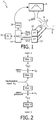
- the used FOT device 2 consists of a patient interface device 4 connected to an airway of a subject to create a pneumatic system that includes an airway of such a subject.
- Patient interface device 4 is any device suitable to provide a pneumatic connection with the airway of a subject, such a mask or mouthpiece.
- Patient interface device 4 is operatively coupled to an exitation source 6 that generates pressure waves, flow changes, or volume changes with relatively low frequencies, for example frequencies from 8 to 24 Hz.
- patient interface device 4 is a loudspeaker.
- a patient breathes air through a mesh-wired resistance 9 that is near to pneumotach head 8, which is located between the patient interface device 4 and exitation source 6.
- the forced waves are partly reflected in the airways and lungs of the patient and lead to oscillations in airflow and pressure which are measured in the FOT device 2.
- the airflow through the pneumotach head 8 is measured using a differential pressure transducer 10 and the pressure is measured using a second pressure transducer 12 near to the mouthpiece 4.
- An analog-to-digital convertor 12 yields respective time series of flow and pressure, ⁇ q t ⁇ and ⁇ p t ⁇ , where the integer t is the discrete time index, which are provided to a processor or computer 16 for analysis.
- the computer or processor 16 can also provide the signals for controlling the frequency of the acoustic waves generated by the loudspeaker 6 via the analog-to-digital convertor 14 and an amplifier 18. Further details of a specific embodiment of the apparatus 2 are provided in the section below entitled "The measurement apparatus".
- the present invention also contemplates that other gas flow delivery devices can be coupled to the airway of the subject in addition to excitation source 6.
- a pressure support system or ventilator can be coupled to patient interface device 4 to provide a flow of gas, for example, while excitation source 6 oscillates the airway of the subject.
- the flow and pressure measurements can be made at any location along the pneumatic system, including measuring the pressure and flow within the pressure support system or ventilator. The measured pressure and flow can then be used to determine the flow and pressure of the gas in the pneumatic system, such as at the airway of the patient, using any conventional technique.
- excitation source 6 can be a components of the pressure support system or the ventilator rather than a stand-alone apparatus.
- a pressure support system or ventilator may include a valve to control the flow/pressure of gas delivered to the patient.
- the present invention contemplates oscillating such a valve to produce the low frequency pressure waves, flow changes, or volume changes.
- any other device or system that is capable of generating the low frequency pressure waves, flow changes, or volume changes, such as a piston can be used as excitation source 6.
- the present invention also contemplates that the flow or the pressure can be set or controlled, such as by the pressure support system or ventilator.
- the set pressure or the set flow is used as the flow of pressure for present purposes rather than the output of differential pressure transducer 10 or second pressure transducer 12.
- x u-jN x u .
- the N ⁇ N matrix in this equation is a circulant (a square matrix whose rows are right-shifted versions of the previous row, with wraparound at the edges).
- the circulant may also be written as circ h qx H . .
- x ⁇ ⁇ x 0 , ...,x N- 1 ⁇ C qx ⁇ circ h qx H and q p ⁇ ⁇ q p, 0 ,...,q p,N- 1 ⁇ .
- q p C qx x .
- x is written as the weighted sum of N harmonic oscillations with frequencies f n .
- the complex number H qx,n is the transfer function from x to q for frequency f n , defined as H qx , n ⁇ h qx H f n .
- the impedance for frequency f n is z n ⁇ H px , n / H qx , n .
- Circulants are normal matrices (they commute with their Hermitian transpose). Eq. 18 is therefore in agreement with the spectral theorem, which says that an N ⁇ N normal matrix has N orthogonal eigenvectors (in this case, the N orthogonal column vectors f n ).
- ⁇ t 2 is the second moment of inertia of the set of point masses about an axis (perpendicular to the plane of the circle) through the reference point R (corresponding to time t R ). As depicted in Figure 3B , this moment of inertia is directly related to the center of gravity. Geometrically, ⁇ t equals the distance from R to one of the two points where the vertical line through the center of gravity intersects with the circle. So, ⁇ t is fully determined by the horizontal distance from the center of gravity to R. If the center of gravity coincides with R, then the weight of x is entirely concentrated at time t R and ⁇ t is zero.
- the components of F x are associated with frequencies f n ⁇ n / N. The same components would be obtained for frequencies n / N + j , where j is any integer (see Eqs. 9, 10 ) .
- the components of F x are therefore periodic in the frequency domain, with unit period. A comparable measure of uncertainty can thus be defined in the frequency domain, relative to a reference frequency f R .
- This ratio (a Rayleigh quotient) can take values in the range from the minimal to the maximal squared singular value of C. This yields the corresponding uncertainty principle for discrete time and frequency, ⁇ min 2 ⁇ ⁇ t 2 + N 2 ⁇ f 2 ⁇ ⁇ max 2 .
- ⁇ t and ⁇ f are both very small, since the total uncertainty ⁇ t 2 + N 2 ⁇ f 2 should at least be equal to ⁇ min 2 .
- the total uncertainty is minimal if x is an eigenvector of C H C that corresponds to ⁇ min 2 .
- the eigenvectors of C H C can be regarded as discrete Mathieu functions.
- An interesting property of C H C is that it commutes with F , so that C H C and F share the same eigenvectors.
- Figure 4 shows the time series for which the sum ⁇ t 2 + N 2 ⁇ f 2 is minimal.
- This is also an eigenvector of the Fourier matrix F (with unit eigenvalue), so that the time series remains unchanged after transformation to the discrete frequency domain (lower graph).
- both of the time and frequency axes are circularly shifted for visual reasons.
- the discrete time-frequency domain partitions a time series of N events into a set of oscillations with N different frequencies.
- the resulting uncertainty in time and frequency is minimal if each short-lasting oscillation is 'windowed' with the components of v min .
- v min m is in fact a circularly shifted version of v min in the frequency domain. As is illustrated in Figure 4 and proven in the "Derivation of the uncertainty principle" section below (see Eq. B19 ), it has the same uncertainty in time and frequency as the eigenvector v min (if f m is taken as reference frequency). Let the components of v min m be denoted by v min , t m . An N -vector that describes a short-lasting oscillation is then obtained by inserting zeros in the middle of v min m (so that the unimodal structure of the vector remains intact).
- N ⁇ N matrix M m be defined as M m ⁇ circ h m , 0 H .
- Premultiplication of x by M m gives an N -vector that may be denoted by a tilde or 'wave sign', x ⁇ m ⁇ M m x .
- the components of x ⁇ m are the inner products x ⁇ m , t ⁇ h m , t H x .
- TFT time-frequency transform
- Transformation to 'the' discrete time-frequency domain is performed by premultiplication of x by M (specific for a given M ). This gives the MN -vector x ⁇ ⁇ M x .
- M H x ⁇ M H M x .
- the time series is thus written as the weighted sum of MN short-lasting oscillations, each centered about time t and frequency f m (cf. Eq. 14 ) .
- these oscillations give an optimal time-frequency resolution according to the uncertainty principle of Eq. 25.
- f n ⁇ f N ⁇ n .
- a set of other oscillations can be added to the excitation source input of Eq. 35, provided that ⁇ f of the used TFT is small enough so that these oscillations are well separated in the time-frequency domain.
- the random variable ⁇ Q ⁇ e,m ⁇ 2 / N may be called the 'TFT sample power spectrum' of the noise Q e .
- the transfer function of filter 1 from noise 1 to Q e,t ( Figure 2 ) is relatively flat in the passband of the TFT filter about f m .
- Q ⁇ e,m is approximately distributed as if it were derived from white noise with zero mean and variance ⁇ Q , m 2 I .
- ⁇ Q ⁇ e , m ⁇ 2 / ⁇ Q , m 2 follows an approximate chi-square distribution with equivalent degrees of freedom ⁇ .
- the best-fitting estimators of b Q,t,m and b P,t,m can be derived from x ⁇ t,m , Q ⁇ t,m and P ⁇ t,m by minimizing the squared norm of the error vectors. This yields the least-squares estimators B ⁇ Q,t,m and B ⁇ P,t,m .
- the excitation source input x ⁇ t,m is a fixed variable
- the flow Q ⁇ t,m and pressure P ⁇ t,m are random variables.
- the vectors Q ⁇ p,t,m and P ⁇ p,t,m are the projections of Q ⁇ t,m and P ⁇ t,m onto the complex one-dimensional subspace spanned by x ⁇ t,m (the line l ).
- the error vectors Q ⁇ e,t,m and P ⁇ e,t,m are perpendicular to x ⁇ t,m .
- Each vector is represented by an arrow whose length equals the norm.
- the angles between the vectors are drawn so that cos 2 ⁇ and cos 2 ⁇ equal the squared coherences between x ⁇ t,m and, respectively, Q ⁇ t,m and P ⁇ t,m .
- the random variable x ⁇ t , m H Q ⁇ t , m / N may be called the 'TFT sample cross spectrum' from x to Q.
- K Qx , t , m 2 equals cos 2 ⁇ , where ⁇ is the angle from x ⁇ t,m to Q ⁇ t,m in Figure 5 .
- K Px , t , m 2 equals cos 2 ⁇ .
- B ⁇ Q,t,m is the ratio of the sample cross spectrum from x to Q to the sample power spectrum of x.
- the 'true' impedance z t,m has a real part r t,m ('resistance') and imaginary part x t,m ('reactance').
- the 100(1- ⁇ )% confidence region for b Q,t,m is delimited by a circle in the complex plane, centered about B ⁇ Q,t,m .
- the confidence region is given by b Q , t , m ⁇ B ⁇ Q , t , m 2 ⁇ B ⁇ Q , t , m 2 A Q , t , m 2 , where A Q , t , m 2 ⁇ F ⁇ ⁇ 2 1 ⁇ K Qx , t , m 2 / ⁇ ⁇ 2 K Qx , t , m 2 and F ⁇ is the upper 100(1- ⁇ )% point of the F -distribution (see the section entitled "Derivation of confidence limits" below).
- the relation will be rejected if the origin is within the circle (then B ⁇ Q,t,m is not significantly different from zero at the 100 ⁇ % confidence level).
- significance is obtained if A Q,t,m ⁇ 1.
- the confidence region for B ⁇ P,t,m is delimited by a comparable circle and the relation between x ⁇ t , m and P ⁇ t,m is considered significant if A P,t,m ⁇ 1.
- a conservative estimate of the confidence region for ⁇ t,m is derived in the section entitled "Derivation of confidence limits" below, under the assumption that Q ⁇ e,t,m and P ⁇ e,t,m are uncorrelated.
- the region is described by z t , m ⁇ Z ⁇ t , m 1 + A Q , t , m A P , t , m 1 ⁇ A Q , t , m 2 2 ⁇ Z ⁇ t , m A Q , t , m + A P , t , m 1 ⁇ A Q , t , m 2 2 2
- the limiting circle is not concentric about the estimator ⁇ t,m .
- the real and imaginary parts of ⁇ t,m are represented by R ⁇ t,m and X ⁇ t,m .
- the vertical arrow indicates the upper confidence limit for the real part and the horizontal arrow indicates the lower confidence limit for the imaginary part of the impedance.
- the distribution of 'true' z t,m for a given realization of ⁇ t,m is apparently skew-symmetric.
- the skewness is determined by the angle ⁇ .
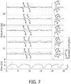
- Figure 7 shows the real and imaginary parts of the estimated impedance ⁇ t,m as a function of time and frequency for a normal subject.
- the blue lines represent the real part R ⁇ t,m and the red lines represent the imaginary part X ⁇ t,m .
- the grey lines represent the confidence limits as depicted in Figure 6B .
- the right hand axis of the 8 Hz frequency band indicates the scale of the components of impedance.
- the real part R ⁇ t,m is positive and fluctuates in the course of the respiratory cycle, while the imaginary part X ⁇ t,m is almost equal to zero and remains relatively constant.
- the confidence limits give an immediate impression of the statistical significance of the changes in R ⁇ t,m and X ⁇ t,m in the course of time.
- Figure 8 shows the impedance for a patient with COPD with large negative swings in X ⁇ t,m during expiration (which are obviously significantly different from the inspiratory values in view of the confidence limits).
- negative swings have previously been described in COPD and are related to flow limitation due to submaximal collapse of the airways during expiration.
- the confidence region is maximal at the turning points from inspiration to expiration and vice versa, probably due to the high-frequency content of the patient's own breathing, which disturbs the forced oscillations. See section “Derivation of confidence limits" below for the coherence spectra.
- FIG. 9 is a flow chart that summarizes the steps in the method according to the invention.
- pressure waves are generated using a loudspeaker connected to a mouthpiece as a patient interface device 4 that is in communication with an airway of a subject (step 101).
- the oscillations in flow and pressure of the gas passing through the mouthpiece 4 are measured to give a respective time series of measurements (step 103).
- the respiratory impedance can be inferred from forced pressure oscillations in the mouthpiece 4 of a quietly breathing subject. Since the mechanical properties of the respiratory system often change from inspiration to expiration, the method estimates the impedance under circumstances of temporary 'stability'.
- the main problem is that impedance is a frequency-dependent quantity and that a high time resolution inevitably leads to a low frequency resolution, thereby distorting the estimation. Since the data consists of discrete time series (sequential measurements of flow and pressure in the mouthpiece 4), this asks for an optimal time-frequency analysis of short time series.
- the present invention is based on the concept that a short time series can be stationary if time is assumed to be circular (see below).
- a new version of the uncertainty principle has been derived for such time series, which poses a lower limit to the total uncertainty in the time and frequency domain.
- this principle is used to partition the variance of each time series into components that are associated with a specific time and frequency (through transformation to the 'discrete time-frequency domain' or 'time-frequency domain').
- Least squares analysis in the time-frequency domain then gives an unbiased estimator of impedance with optimal time-frequency resolution (step 107).
- confidence limits for impedance have been constructed as a function of time and frequency. The main steps are summarized and discussed below.
- the linear model The estimation of respiratory impedance is based on a simple linear model ( Eq. 3, Figure 2 ). Oscillations in the mouthpiece 4 of the apparatus 2 are induced by a loudspeaker 6. The resulting changes in flow and pressure depend on the mechanical properties of the patient's respiratory system (the acoustics of that system). In the model, this is expressed by two linear time-invariant filters (2 and 3 in Figure 2 ) that modify the loudspeaker input. The resulting fluctuations in flow and pressure are disturbed by two independent sources of noise in both flow and pressure. The respiratory impedance is determined by the two linear filters (2 and 3).
- Possible sources of noise are: 1) components of the patient's breathing in the frequency range of the forced oscillations, which is probably the most important problem (see reference 2), 2) swallowing, coughing or other movements by the patient, 3) cardiogenic oscillations, in particular when the airway resistance is low, 4) time-dependent variations in respiratory impedance itself and 5) random measurement errors.
- the uncertainty principle. 'Uncertainty in time' is a property of a time series that expresses how much the components of the series are spread in time. For a discrete, finite and circular time series, this gives a figure as shown in Figure 3A .
- the components of the time series are represented by point masses placed at regular intervals around the time circle (each mass equals the squared absolute value of a component).
- the 'uncertainty in frequency ⁇ f expresses the spread in the frequency domain (Eq. 22 ).
- every time series with N components can be written as the sum of N harmonic oscillations with a given amplitude and frequency (representation in the discrete frequency domain).
- these frequencies are also circular.
- the spread in the frequency domain can be visualized by placing the squared amplitudes as N point masses around a circle comparable to that in Figure 3A (each point corresponding to a specific frequency).
- the discrete time-frequency domain The presented time-frequency transform (TFT) partitions a discrete and finite time series into a set of short-lasting oscillations of M components, with M ⁇ N (a transformation to the time-frequency domain). Each oscillation is centered about a specific time and frequency, with minimal uncertainty in both domains according to the principle of Eq. 55.
- the TFT amounts to a windowed 'short-term Fourier transform' or 'running Fourier transform'.
- the short-lasting oscillations maximally overlap each other in time so that the outcome is independent of the time at which the first oscillation starts. Only the oscillations that start before the beginning and end after the end of the time series are dependent on the circularity assumption (these are excluded in the analysis to avoid bias).
- the optimal ⁇ t and ⁇ f according to the uncertainty principle of Eq. 55 depends on M (substitute N by M in Eq. B8, see also Figure 11 ). Not surprisingly, the larger M, the larger the corresponding optimal ⁇ t and the smaller the corresponding ⁇ f . In the present analysis, M is chosen so that ⁇ f is small enough to be able to discern the different oscillations induced by the loudspeaker.
- Input to the loudspeaker a set of five harmonic oscillations we used as an input to the loudspeaker 6 (at frequencies of 8, 12, 16, 20 and 24 Hz respectively).
- M actually an effective value, see Eq. B6
- the TFT coefficients were only computed for these five frequencies, which amounts to band-pass filtering with five resonant frequencies.
- One prior art approach uses a single frequency for the loudspeaker input.
- a ventilator waveform was applied that was built up of nonharmonic sinusoids to ventilated patients to prevent interaction between oscillations at harmonic frequencies.
- Such an approach is however not applicable in freely breathing subjects.
- Some interference of the respiratory system at harmonic frequencies may indeed occur in the present invention, although this has not been observed in the frequency response of the system after broad-band stimulation.
- N S 500 successive values in the time-frequency domain are considered as a sample from this process (an episode of 0.625 s at a sample rate of 800 Hz). It was assumed that at every moment (800 times per second) a new stochastic process of this type starts with a variance that is not necessarily equal to the previous one. Thus, the measurements were subdivided into maximally overlapping episodes of 500 values, each of which was considered as a sample from a different stationary stochastic process. The sources of noise were not assumed to be 'white', but it was assumed that the power was constant in each frequency band of the TFT filter. The mean power during each episode of 500 values then follows an approximate chi-square distribution for which the equivalent degrees of freedom were derived.
- N depends on the time during which the system can be considered as stationary. For respiration, an episode of ⁇ 0.5 s seems plausible, assuming that the impedance is approximately stable in the midst of each inspiration and expiration. In the shown examples, this worked out well ( Figures 7 and 8 ). In most prior art techniques, however, spectra are averaged over a longer episode, usually of more than 10 s. Some averaged spectral values derived from non-overlapping segments of ⁇ 0.65 s over a total episode of 16 s. The use of non-overlapping segments, however, gives considerably less degrees of freedom for an episode of the same length as compared to the maximally overlapping segments used here (i.e., the segments of M values used in the TFT).
- the major problem is that the use of an episode of 16 s averages out possible physiological differences between inspiration and expiration, which are usually more pronounced in diseases such as COPD. In that case, a low coherence between flow and pressure over 16 s is not only a reflection of noise, but also of within-breath variability of impedance (which is part of the disease).
- the duration of the supposed stationarity should not be chosen too short, either.
- the confidence intervals for are relatively wide at the turning points from inspiration to expiration and vice versa. This may be due to high-frequency components of the patient's own breathing. These changes are apparently shorter than 0.5 s, so that they appear as noise in the estimation. The duration of the supposed stationarity should therefore be long enough to 'interpret' these changes as noise.
- time-frequency dependent confidence limits in embodiments of the present invention provide a continuous impression of the validity of the hypothesis that the short-lasting sequences are samples from a stationary stochastic process. They make it possible to test the significance of changes in impedance in the course of time and provide a basis to automatically reject unreliable estimates (like during swallowing in Figure 7 ), which is of practical interest in real-time monitoring.
- FIG 10 is a flow chart illustrating the method performed by the apparatus 2 according to the invention (and particularly the processing steps performed by the computer 16) in more detail.
- step 121 pressure waves are generated using a loudspeaker 6 connected to a mouthpiece 4 that is being used by a subject, and the oscillations in flow and pressure of the air passing through the mouthpiece 4 are measured and digitized to give a respective time series of measurements (step 123).
- flow and pressure are given as a function of discrete time t, q t and p t .
- the frequencies f m are chosen so that they match the frequencies of the imposed FOT frequencies.
- weighting factor w l is described here as being approximated by a Gaussian function, it is to be understood that other windows or weighting factors are contemplated by the present invention, such as a triangle window, a piece-wise linear approximation, or a polynomial function.
- step 127 the power and cross spectra are derived as a function of time and frequency.
- step 129 the power and cross spectra are used to determine the transfer functions from the loudspeaker input to flow and pressure respectively.
- step 133 confidence limits on the respiratory impedance can be derived (step 133) as follows.
- ⁇ tr P H P 2 tr P H P 2
- P is an N ⁇ N matrix
- H stands for the Hermitian transpose
- tr ⁇ for the trace of the matrix.
- F ⁇ is labeled as the upper 100(1 - ⁇ )% point of the F-distribution on 2, ⁇ - 2 degrees of freedom.
- K xq , t , m 2 C xq , t , m 2 P x , t , m ⁇ P q , t , m
- a q , t , m 2 F ⁇ 2 ⁇ ⁇ 2 1 ⁇ K xq , t , m 2 K xq , t , m 2
- a p , t , m 2 F ⁇ 2 ⁇ ⁇ 2 1 ⁇ K xp , t , m 2 K xp , t , m 2
- the estimates of respiratory impedance for a given time and frequency are rejected as not significant if either A q,t,m ⁇ a first threshold, or A p,t,m ⁇ a second threshold.
- the first threshold and the second threshold are set to 1 (one), so that the estimates of respiratory impedance for a given time and frequency are rejected as not significant if either A q,t,m ⁇ 1 or A p,t,m ⁇ 1.
- the algorithm contains several circular data buffers.
- the measurement apparatus The measurement apparatus
- the airflow can be measured with a pneumotach head 8 and built-in pressure transducer 10 (for example a Jaeger Masterscreen pneumotach type BF/IEC 601-1, Hoechberg, Germany).
- the pressure at the mouthpiece 4 can be measured with reference to ambient air with a differential pressure transducer 12 (for example a Hans Rudolph Pneumotach amplifier 1 series 1110, Shawnee, KS).
- the pressure oscillations can be generated in the FOT device 2 by a loudspeaker 6 (for example a Jaeger Masterscreen IOS, Hoechberg, Germany) that is controlled by an analog output signal from a personal computer 16 (for example a Hewlett Packard Compac dc 7600, Palo Alto, CA) through an analog-digital conversion card 14 (for example a National Instruments PCI-6221, Dallas, TX), which is amplified by an amplifier 18 (for example a Harman Kardon HK 970 amplifier, Washington DC)). Subjects can breathe in and out through the mesh-wired resistance 9 connected to the pneumotach head 8.
- a loudspeaker 6 for example a Jaeger Masterscreen IOS, Hoechberg, Germany
- an analog output signal from a personal computer 16 (for example a Hewlett Packard Compac dc 7600, Palo Alto, CA) through an analog-digital conversion card 14 (for example a National Instruments PCI-6221, Dallas, TX), which is
- Analog input signals can be converted to digital sequences through the same analog-digital conversion card 14 at a sample rate of 800 Hz and stored in the personal computer 16.
- the generation of the output signal and the analysis of the data can be performed by a computer or processor 16 executing appropriate computer software.
- Measurements can be made using the apparatus 2 during a period covering a number of breathing cycles, for example 90 seconds of quiet breathing.
- the uncertainty ⁇ t is directly related to the 'center of gravity of the time series x ⁇ ⁇ x t ⁇ .
- the events in the time series are represented as point masses with value
- Each event occurs at a point r t ⁇ t in the complex plane, with r t ⁇ N / (2 ⁇ ) and ⁇ ⁇ exp(2 ⁇ i / N ).
- the center of gravity is located at r t ⁇ t .
- ⁇ ⁇ t ⁇ x H ⁇ x / ⁇ x ⁇ 2 where ⁇ ⁇ diag ⁇ 1, ⁇ ,..., ⁇ N -1 ⁇ .
- the eigenvectors are mapped along the time circle in the complex plane with radius r t , centered about the origin.
- the centers of gravity of each eigenvector are depicted by black dots.
- the corresponding singular value of C is minimal for the center of gravity at the right (near to the reference point R) and gradually increases to the left of the Figure.
- the uncertainty ⁇ t for each eigenvector is the oblique distance from R to one of the intersection points of the vertical line through the center of gravity and the circle.
- the uncertainty ⁇ f can be geometrically interpreted in a similar manner.
- v be a unit eigenvector of C H C that corresponds to singular value ⁇ .
- Equation B5 is comparable to the Schrödinger equation for a quantum harmonic oscillator.
- the solutions can be regarded as discrete orthogonal Mathieu functions.
- the eigenvector v min that corresponds to ⁇ min is a unimodal function of time (as in Figure 4A ).
- the norm ⁇ d ⁇ can be taken as a measure for the error made by the approximation. Using appropriate mathematical software, it follows that the relative error ⁇ d ⁇ / ⁇ v ⁇ is less than 0.005 if N > 75.
- ⁇ t , min ⁇ min / 2 ⁇ r t / 2
- ⁇ t , max ⁇ max / 2 ⁇ 2 r t .
- the accessible region for all possible N -vectors x is bounded by the two circles with radius ⁇ min and ⁇ max (the minimal and maximal singular value of C).
- r t is the radius of the time circle
- the black dots belong to the eigenvectors of C H C
- v min and v max are eigenvectors corresponding to ⁇ min and ⁇ max
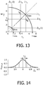
- Figure 13 shows N ⁇ f as a function of ⁇ t . Due to the uncertainty principle of Eq. 25, the accessible region is bounded by two circles centered about the origin, with radius ⁇ min and ⁇ max . This does not mean that all values between these circles are possible, but that all values outside the circles are impossible.
- the coordinates that belong to the eigenvectors of C H C are all located on the identity line (due to Eq. B7 ). Some extreme cases are also shown.
- the main difference between the inequalities of Eq. B11 and Eq. 25 lies in the fact that according to Gabor's uncertainty principle, the lower limit of ⁇ t ⁇ f is attained for Gaussian functions of t (of the same form as in Eq. B6 ) with any nonzero value of ⁇ t (see reference 5). This is a set of linearly independent (infinite) vectors.
- the lower limit of the total uncertainty ⁇ t 2 + N ⁇ f 2 according to Eq. 25, however, is attained for only one eigenspace of C H C (the complex one-dimensional subspace spanned by v min ), which corresponds to one single value of ⁇ t (equal to ⁇ min / 2 ).
- N a number of N -1 vectors can be derived by adding zeros to smaller M -dimensional v min vectors that are obtained from M ⁇ M matrices C H C.
- ⁇ f of these vectors is maximized without a change in ⁇ t .
- the points in zone VI are obtained from the vectors in zone I, premultiplied by T 8 , which circularly shifts the vectors in the time domain (thereby maximizing ⁇ t without a change in ⁇ f ).
- the vectors in zone V follow from those in zone II through premultiplication by T 8 .
- the vectors in zone VIII follow from those in zone I by taking the Fourier transform (premultiplication by F means reflection in the identity line).
- Premultiplying these vectors by ⁇ 8 gives the vectors in zone III
- premultiplying by T 8 gives the vectors in zone VII
- premultiplying the latter again by ⁇ 8 gives those in zone IV.
- Its components are g m , u ⁇ ⁇ h m H T ⁇ u h m , 0 ⁇ u ⁇ M ⁇ 1 , or N ⁇ M + 2 ⁇ u ⁇ N ⁇ 1 ; 0 , otherwise .
- N -vector h m Eqs. 26 and 27
- T k ⁇ n ⁇ - nk ⁇ n T k
- Time-frequency synthesis A direct corollary of the orthonormality property is that a given time series vector x can be written as the weighted sum of short-lasting oscillations ( Eq. 34 ).
- the quadratic form ⁇ X ⁇ 2 / ⁇ 2 follows a chi-square distribution on N degrees of freedom.
- ⁇ X ⁇ 2 can be partitioned into M frequency-dependent components ⁇ X ⁇ m ⁇ 2 .
- the quadratic form ⁇ X ⁇ m ⁇ 2 / N may be called the 'TFT sample power spectrum' of X for frequency f m .
- the sample power spectrum according to the definition above is however sensitive to bias due to the circularity assumption.
- the components of X ⁇ m ⁇ M m X are derived from X by circular convolution with a linear time-invariant filter with M nonzero elements ( Eqs. 26-31 ).
- the structure of this filter is such that the first M - K - 1 and the last K components of X ⁇ m are dependent on the circularity assumption (provided these integers are larger than zero), where K is the largest integer less than or equal to M /2 .
- a power estimator free of bias due to the circularity assumption is thus obtained with the 'selection matrix' S , defined as S ⁇ diag 0 , ... , 0 ⁇ M ⁇ K ⁇ 1 1 , ... , 1 ⁇ N ⁇ M + 1 0 , ... , 0 ⁇ K
- Premultiplication of X ⁇ m by S selects the components of X ⁇ m that are independent of the circularity assumption, which gives the unbiased quadratic form ⁇ S M m X ⁇ 2 .
- N S N - M + 1.
- B ⁇ Q,t,m is an unbiased estimator of b Q,t,m .
- ⁇ Q ⁇ e , t , m ⁇ 2 ⁇ x ⁇ t , m ⁇ 2 ⁇ B ⁇ Q , t , m ⁇ b Q , t , m 2 + ⁇ Q ⁇ e , t , m ⁇ 2
- the random variable ⁇ x ⁇ t , m ⁇ 2 B ⁇ Q , t , m ⁇ b Q , t , m 2 / ⁇ Q , m 2 has the form B ⁇ Q , t , m ⁇ E B ⁇ Q , t , m H var B ⁇ Q , t , m ⁇ 1 B ⁇ Q , t , m ⁇ E B ⁇ Q , t , m and is thus (exactly) distributed as a chi-square variable (on one degree of freedom).
- the 100(1 - ⁇ )% confidence region for B ⁇ Q,t,m is thus described by a circle in the complex plane with center B ⁇ Q,t,m and radius
- the confidence region for B ⁇ P,t,m is derived in a similar manner, B ⁇ P , t , m ⁇ b P , t , m 2 ⁇ B ⁇ P , t , m 2 A P , t , m 2
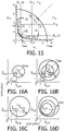
- U lies within a circle with center C u ⁇ Z ⁇ t , m / 1 ⁇ A Q , t , m 2 and radius r u ⁇ Z ⁇ t , m A Q , t , m / 1 ⁇ A Q , t , m 2 , on 100(1- ⁇ )% of occasions ( Figure 16A ).
- Q ⁇ e,t , m and P ⁇ e,t,m are uncorrelated.
- This region is delimited by the circle in Figures 16B and 16C with center C 2 ⁇ Z ⁇ t , m 1 + A Q , t , m A P , t , m / 1 ⁇ A Q , t , m 2 and radius r 2 ⁇ Z ⁇ t , m A Q , t , m + A P , t , m / 1 ⁇ A Q , t , m 2 .
- This circle is not concentric about ⁇ t,m .
- the distribution of possible values for z t,m for a given ⁇ t,m is skew-symmetric about ⁇ t,m ( Figure 16D ).
- the skewness parameter tan ⁇ equals A Q,t,m .
- FIG. 17 shows the squared coherences for the same recording as in Figure 7 .
- the coherence between loudspeaker input and flow was generally lower than the coherence between input and pressure.
- the coherences change as a function of both time and frequency. The smallest coherences are obtained at the turning points from inspiration to expiration and vice versa, and at the lowest frequencies. Swallowing has a deep impact on coherence, especially between input and flow.
- Figure 18 shows the squared coherences as a function of time and frequency for the estimated impedance shown in Figure 8 for a patient with COPD.
- the estimate of respiratory impedance may be made by a diagnostic tool that uses the estimate to assess obstruction of the airways or to estimate the severity of disease.
- the diagnostic tool may therefore also be used to assess the effectiveness of treatments (whether pharmacological or otherwise) that should affect the respiratory impedance.
- the estimates of respiratory impedance can be used to detect (i) expiratory flow limitation in chronic obstructive lung disease (COPD); (ii) the severity of airway obstruction in COPD or asthma, which itself be used to evaluate the effect of inhaled airway dilators (e.g. sympathicomimetic or parasympathicolytic drugs) over the course of time (this can be applicable to a research setting and also to a clinical setting where the patient is unable to perform the standard forced respiratory maneuvers; (iii) airway obstruction in asthma or COPD during sleep; or (iv) upper airway obstruction during sleep in patients suspected of sleep apnea-hypopnea syndrome.
- COPD chronic obstructive lung disease
- the estimates of respiratory impedance may also or alternatively be used to adapt the settings of machine used in the treatment of a medical condition.
- the estimates of respiratory impedance can be used in the adjustment of settings of noninvasive ventilation in COPD.
- the respiratory impedance can be used as an input to the ventilator to provide information on the severity of the airway impedance on a continuous basis (with unreliable values, as indicated by the confidence values, being discarded). This information can also be used to adjust the level of bilevel positive airway pressure with which the expiratory flow limitation is just overcome.
- the estimates of respiratory impedance can be used as an aid to guide the level of continuous positive airway pressure in patients with obstructive sleep apnea syndrome.
- a computer program may be stored/distributed on a suitable medium, such as an optical storage medium or a solid-state medium supplied together with or as part of other hardware, but may also be distributed in other forms, such as via the Internet or other wired or wireless telecommunication systems. Any reference signs in the claims should not be construed as limiting the scope.
Landscapes
- Health & Medical Sciences (AREA)
- Life Sciences & Earth Sciences (AREA)
- Pulmonology (AREA)
- Engineering & Computer Science (AREA)
- Physics & Mathematics (AREA)
- Surgery (AREA)
- General Health & Medical Sciences (AREA)
- Biophysics (AREA)
- Biomedical Technology (AREA)
- Heart & Thoracic Surgery (AREA)
- Medical Informatics (AREA)
- Molecular Biology (AREA)
- Physiology (AREA)
- Animal Behavior & Ethology (AREA)
- Pathology (AREA)
- Public Health (AREA)
- Veterinary Medicine (AREA)
- Mathematical Physics (AREA)
- Artificial Intelligence (AREA)
- Computer Vision & Pattern Recognition (AREA)
- Psychiatry (AREA)
- Signal Processing (AREA)
- Measurement Of The Respiration, Hearing Ability, Form, And Blood Characteristics Of Living Organisms (AREA)
- Measuring Pulse, Heart Rate, Blood Pressure Or Blood Flow (AREA)
Priority Applications (1)
| Application Number | Priority Date | Filing Date | Title |
|---|---|---|---|
| EP10800788.1A EP2506765B1 (en) | 2009-12-03 | 2010-11-24 | Method and apparatus for estimating respiratory impedance |
Applications Claiming Priority (3)
| Application Number | Priority Date | Filing Date | Title |
|---|---|---|---|
| EP09177892 | 2009-12-03 | ||
| EP10800788.1A EP2506765B1 (en) | 2009-12-03 | 2010-11-24 | Method and apparatus for estimating respiratory impedance |
| PCT/IB2010/055392 WO2011067698A2 (en) | 2009-12-03 | 2010-11-24 | Method and apparatus for estimating respiratory impedance |
Publications (2)
| Publication Number | Publication Date |
|---|---|
| EP2506765A2 EP2506765A2 (en) | 2012-10-10 |
| EP2506765B1 true EP2506765B1 (en) | 2021-01-06 |
Family
ID=43877324
Family Applications (1)
| Application Number | Title | Priority Date | Filing Date |
|---|---|---|---|
| EP10800788.1A Active EP2506765B1 (en) | 2009-12-03 | 2010-11-24 | Method and apparatus for estimating respiratory impedance |
Country Status (7)
| Country | Link |
|---|---|
| US (1) | US9649050B2 (enExample) |
| EP (1) | EP2506765B1 (enExample) |
| JP (1) | JP5868866B2 (enExample) |
| CN (1) | CN102639056B (enExample) |
| BR (1) | BR112012013000A2 (enExample) |
| RU (1) | RU2606107C2 (enExample) |
| WO (1) | WO2011067698A2 (enExample) |
Families Citing this family (20)
| Publication number | Priority date | Publication date | Assignee | Title |
|---|---|---|---|---|
| CN104023633B (zh) * | 2011-12-30 | 2017-05-24 | 皇家飞利浦有限公司 | 与呼吸处置设备整合的气道阻抗测量 |
| JP6031896B2 (ja) * | 2012-08-29 | 2016-11-24 | アイシン精機株式会社 | 呼吸信号推定装置及び呼吸信号推定方法 |
| WO2014097047A1 (en) * | 2012-12-19 | 2014-06-26 | Koninklijke Philips N.V. | Detection of respiratory disorders |
| US10064583B2 (en) * | 2013-08-07 | 2018-09-04 | Covidien Lp | Detection of expiratory airflow limitation in ventilated patient |
| WO2015106065A1 (en) * | 2014-01-10 | 2015-07-16 | Cgg Services (U.S.) Inc. | Device and method for mitigating cycle-skipping in full waveform inversion |
| EP2945084A1 (en) * | 2014-05-12 | 2015-11-18 | Electrosalus Biyomedikal Sanayi ve Ticaret Anonim Sirketi | Auscultation data acquisition, communication and evaluation system incorporating mobile facilities |
| US20170135603A1 (en) * | 2014-07-01 | 2017-05-18 | Kosmo Technologies, Inc. | Methods and devices for positioning of a mandible of a subject for determining an optimal airway opening |
| CN108136146B (zh) * | 2015-09-28 | 2021-05-11 | 皇家飞利浦有限公司 | 在存在泄漏的情况下估计患者回路的依从性的方法和系统 |
| US11357421B2 (en) | 2016-02-03 | 2022-06-14 | Cognita Labs, LLC | Forced oscillation technique based lung function testing |
| EP3658021B1 (en) * | 2017-07-26 | 2024-02-07 | Thorasys Thoracic Medical Systems Inc. | Method and system to acquire oscillometry measurements |
| US11433202B2 (en) * | 2017-12-18 | 2022-09-06 | Koninklijke Philips N.V. | Interactive guidance related to a subject's expiratory flow limitation results |
| WO2020093176A1 (en) * | 2018-11-09 | 2020-05-14 | Thorasys Thoracic Medical Systems Inc. | Modular oscillometry device with dynamic calibration |
| GB2583117B (en) * | 2019-04-17 | 2021-06-30 | Sonocent Ltd | Processing and visualising audio signals |
| US11872344B2 (en) * | 2019-09-30 | 2024-01-16 | Koninklijke Philips N.V. | Detecting and treating COPD-OSA overlap syndrome |
| CN116165539B (zh) * | 2023-03-23 | 2026-03-17 | 华北电力科学研究院有限责任公司 | 电力机组振荡检测方法和装置 |
| CN116458872B (zh) * | 2023-06-13 | 2023-09-05 | 汶上县人民医院 | 一种呼吸数据的分析方法及系统 |
| CN118830827B (zh) * | 2024-06-20 | 2025-11-28 | 中国医学科学院生物医学工程研究所 | 呼吸参数测量系统和方法 |
| CN118787336B (zh) * | 2024-06-20 | 2025-11-28 | 中国医学科学院生物医学工程研究所 | 呼吸参数动态测量方法、系统、存储介质及程序产品 |
| CN120093273B (zh) * | 2025-05-07 | 2025-09-02 | 南方科技大学 | 基于肺部二叉树模型的痰液阻塞检测方法、系统、终端及介质 |
| CN120820988B (zh) * | 2025-06-20 | 2026-08-04 | 中煤科工西安研究院(集团)有限公司 | 一种混合时频分析的钻孔雷达数据高分辨处理方法 |
Family Cites Families (12)
| Publication number | Priority date | Publication date | Assignee | Title |
|---|---|---|---|---|
| SU1635959A1 (ru) * | 1987-07-09 | 1991-03-23 | Петрозаводский государственный университет им.О.В.Куусинена | Способ определени нарушений бронхиальной проходимости |
| US5318038A (en) * | 1993-01-19 | 1994-06-07 | Trustees Of Boston University | Infant respiratory impedance measuring apparatus and methods using forced oscillations |
| US5555880A (en) * | 1994-01-31 | 1996-09-17 | Southwest Research Institute | High frequency oscillatory ventilator and respiratory measurement system |
| US5885225A (en) | 1996-01-23 | 1999-03-23 | Boys Town National Research Hospital | System and method for the measurement of evoked otoacoustic emissions |
| US5795304A (en) * | 1996-03-27 | 1998-08-18 | Drexel University | System and method for analyzing electrogastrophic signal |
| US6142952A (en) * | 1997-10-29 | 2000-11-07 | The Board Of Regents, The University Of Texas System | Method and apparatus for detection and diagnosis of airway obstruction degree |
| US6066101A (en) | 1998-04-20 | 2000-05-23 | University Of Maryland | Airflow perturbation device and method for measuring respiratory resistance |
| FR2791248B1 (fr) * | 1999-03-24 | 2001-08-24 | Georges Kehyayan | Dispositif d'analyse de bruits auscultatoires, en particulier de bruits respiratoires |
| ITMI20021273A1 (it) * | 2002-06-11 | 2003-12-11 | Milano Politecnico | Sistema e metodo per la rilevazione automatica della limitazione del flusso espiratorio |
| AU2004208574B2 (en) * | 2003-01-30 | 2007-08-30 | Compumedics Limited | Algorithm for automatic positive air pressure titration |
| AU2005237191A1 (en) * | 2004-05-04 | 2005-11-10 | Dalhousie University | Method of assessment of airway variability in airway hyperresponsiveness |
| JP5198162B2 (ja) * | 2008-03-10 | 2013-05-15 | チェスト株式会社 | 呼吸インピーダンス測定装置及びその測定方法 |
-
2010
- 2010-11-24 CN CN201080054374.1A patent/CN102639056B/zh active Active
- 2010-11-24 BR BR112012013000A patent/BR112012013000A2/pt not_active Application Discontinuation
- 2010-11-24 US US13/511,207 patent/US9649050B2/en active Active
- 2010-11-24 WO PCT/IB2010/055392 patent/WO2011067698A2/en not_active Ceased
- 2010-11-24 EP EP10800788.1A patent/EP2506765B1/en active Active
- 2010-11-24 RU RU2012127567A patent/RU2606107C2/ru active
- 2010-11-24 JP JP2012541607A patent/JP5868866B2/ja active Active
Non-Patent Citations (1)
| Title |
|---|
| None * |
Also Published As
| Publication number | Publication date |
|---|---|
| US20120289852A1 (en) | 2012-11-15 |
| CN102639056B (zh) | 2015-08-05 |
| WO2011067698A3 (en) | 2011-09-01 |
| JP2013512718A (ja) | 2013-04-18 |
| US9649050B2 (en) | 2017-05-16 |
| RU2012127567A (ru) | 2014-01-20 |
| RU2606107C2 (ru) | 2017-01-10 |
| WO2011067698A2 (en) | 2011-06-09 |
| JP5868866B2 (ja) | 2016-02-24 |
| CN102639056A (zh) | 2012-08-15 |
| EP2506765A2 (en) | 2012-10-10 |
| BR112012013000A2 (pt) | 2018-08-28 |
Similar Documents
| Publication | Publication Date | Title |
|---|---|---|
| US9649050B2 (en) | Method and apparatus for estimating respiratory impedance | |
| Bates et al. | Oscillation mechanics of the respiratory system | |
| US6435182B1 (en) | Enhanced ventilation waveform device | |
| Cohen et al. | Comparison of impedance and inductance ventilation sensors on adults during breathing, motion, and simulated airway obstruction | |
| Vicario et al. | Noninvasive estimation of respiratory mechanics in spontaneously breathing ventilated patients: a constrained optimization approach | |
| US20080082018A1 (en) | Systems and methods for respiratory event detection | |
| US20160135715A1 (en) | Method for respiratory measurement | |
| US20150164413A1 (en) | Method of creating anesthetic consciousness index with artificial neural network | |
| Houssein et al. | Estimation of respiratory variables from thoracoabdominal breathing distance: a review of different techniques and calibration methods | |
| Bates | CORP: Measurement of lung function in small animals | |
| EP3973866A1 (en) | A processor and method for determining a respiratory rate | |
| CN111353972B (zh) | 状态评估系统、诊疗系统及其操作方法 | |
| US10149647B2 (en) | Weaning readiness indicator, sleeping status recording device, and air providing system applying nonlinear time-frequency analysis | |
| Nguyen-Ky et al. | Measuring and reflecting depth of anesthesia using wavelet and power spectral density | |
| Sello et al. | Respiratory sound analysis in healthy and pathological subjects: A wavelet approach | |
| Ionescu et al. | A novel parametric model for the human respiratory system | |
| Campbell et al. | I Laryngeal Resistance to Air Flow | |
| Zannin et al. | Effect of stimulating waveform and of data processing on respiratory impedance measurement | |
| Matsiki et al. | Wavelet-based analysis of nocturnal snoring in apneic patients undergoing polysomnography | |
| Hasan et al. | Diagnosing COPD using mobile phones | |
| Muthusamy et al. | An overview of respiratory airflow estimation techniques: Acoustic vs non-acoustic | |
| Ionescu et al. | Respiratory impedance model with lumped fractional order diffusion compartment | |
| Alves de Mesquita et al. | Respiratory monitoring system based on the nasal pressure technique for the analysis of sleep breathing disorders: Reduction of static and dynamic errors, and comparisons with thermistors and pneumotachographs | |
| McErlean | Functional Estimation of Manifold-Valued Diffusion Processes with Applications | |
| Kochhar | Respirascan: Using Breathing Patterns As a Biomarker to Diagnose Restrictive Lung Diseases |
Legal Events
| Date | Code | Title | Description |
|---|---|---|---|
| PUAI | Public reference made under article 153(3) epc to a published international application that has entered the european phase |
Free format text: ORIGINAL CODE: 0009012 |
|
| AK | Designated contracting states |
Kind code of ref document: A2 Designated state(s): AL AT BE BG CH CY CZ DE DK EE ES FI FR GB GR HR HU IE IS IT LI LT LU LV MC MK MT NL NO PL PT RO RS SE SI SK SM TR |
|
| AX | Request for extension of the european patent |
Extension state: BA ME |
|
| 17P | Request for examination filed |
Effective date: 20120703 |
|
| R17D | Deferred search report published (corrected) |
Effective date: 20110901 |
|
| RBV | Designated contracting states (corrected) |
Designated state(s): AL AT BE BG CH CY CZ DE DK EE ES FI FR GB GR HR HU IE IS IT LI LT LU LV MC MK MT NL NO PL PT RO RS SE SI SK SM TR |
|
| DAX | Request for extension of the european patent (deleted) | ||
| 17Q | First examination report despatched |
Effective date: 20130627 |
|
| RAP1 | Party data changed (applicant data changed or rights of an application transferred) |
Owner name: KONINKLIJKE PHILIPS N.V. |
|
| STAA | Information on the status of an ep patent application or granted ep patent |
Free format text: STATUS: EXAMINATION IS IN PROGRESS |
|
| RAP1 | Party data changed (applicant data changed or rights of an application transferred) |
Owner name: KONINKLIJKE PHILIPS N.V. |
|
| GRAP | Despatch of communication of intention to grant a patent |
Free format text: ORIGINAL CODE: EPIDOSNIGR1 |
|
| STAA | Information on the status of an ep patent application or granted ep patent |
Free format text: STATUS: GRANT OF PATENT IS INTENDED |
|
| INTG | Intention to grant announced |
Effective date: 20200615 |
|
| GRAS | Grant fee paid |
Free format text: ORIGINAL CODE: EPIDOSNIGR3 |
|
| GRAA | (expected) grant |
Free format text: ORIGINAL CODE: 0009210 |
|
| STAA | Information on the status of an ep patent application or granted ep patent |
Free format text: STATUS: THE PATENT HAS BEEN GRANTED |
|
| AK | Designated contracting states |
Kind code of ref document: B1 Designated state(s): AL AT BE BG CH CY CZ DE DK EE ES FI FR GB GR HR HU IE IS IT LI LT LU LV MC MK MT NL NO PL PT RO RS SE SI SK SM TR |
|
| REG | Reference to a national code |
Ref country code: GB Ref legal event code: FG4D |
|
| REG | Reference to a national code |
Ref country code: AT Ref legal event code: REF Ref document number: 1351441 Country of ref document: AT Kind code of ref document: T Effective date: 20210115 Ref country code: CH Ref legal event code: EP |
|
| REG | Reference to a national code |
Ref country code: DE Ref legal event code: R096 Ref document number: 602010066316 Country of ref document: DE |
|
| REG | Reference to a national code |
Ref country code: IE Ref legal event code: FG4D |
|
| REG | Reference to a national code |
Ref country code: NL Ref legal event code: MP Effective date: 20210106 |
|
| REG | Reference to a national code |
Ref country code: AT Ref legal event code: MK05 Ref document number: 1351441 Country of ref document: AT Kind code of ref document: T Effective date: 20210106 |
|
| REG | Reference to a national code |
Ref country code: LT Ref legal event code: MG9D |
|
| PG25 | Lapsed in a contracting state [announced via postgrant information from national office to epo] |
Ref country code: LT Free format text: LAPSE BECAUSE OF FAILURE TO SUBMIT A TRANSLATION OF THE DESCRIPTION OR TO PAY THE FEE WITHIN THE PRESCRIBED TIME-LIMIT Effective date: 20210106 Ref country code: HR Free format text: LAPSE BECAUSE OF FAILURE TO SUBMIT A TRANSLATION OF THE DESCRIPTION OR TO PAY THE FEE WITHIN THE PRESCRIBED TIME-LIMIT Effective date: 20210106 Ref country code: GR Free format text: LAPSE BECAUSE OF FAILURE TO SUBMIT A TRANSLATION OF THE DESCRIPTION OR TO PAY THE FEE WITHIN THE PRESCRIBED TIME-LIMIT Effective date: 20210407 Ref country code: FI Free format text: LAPSE BECAUSE OF FAILURE TO SUBMIT A TRANSLATION OF THE DESCRIPTION OR TO PAY THE FEE WITHIN THE PRESCRIBED TIME-LIMIT Effective date: 20210106 Ref country code: PT Free format text: LAPSE BECAUSE OF FAILURE TO SUBMIT A TRANSLATION OF THE DESCRIPTION OR TO PAY THE FEE WITHIN THE PRESCRIBED TIME-LIMIT Effective date: 20210506 Ref country code: BG Free format text: LAPSE BECAUSE OF FAILURE TO SUBMIT A TRANSLATION OF THE DESCRIPTION OR TO PAY THE FEE WITHIN THE PRESCRIBED TIME-LIMIT Effective date: 20210406 Ref country code: NO Free format text: LAPSE BECAUSE OF FAILURE TO SUBMIT A TRANSLATION OF THE DESCRIPTION OR TO PAY THE FEE WITHIN THE PRESCRIBED TIME-LIMIT Effective date: 20210406 Ref country code: NL Free format text: LAPSE BECAUSE OF FAILURE TO SUBMIT A TRANSLATION OF THE DESCRIPTION OR TO PAY THE FEE WITHIN THE PRESCRIBED TIME-LIMIT Effective date: 20210106 |
|
| PG25 | Lapsed in a contracting state [announced via postgrant information from national office to epo] |
Ref country code: LV Free format text: LAPSE BECAUSE OF FAILURE TO SUBMIT A TRANSLATION OF THE DESCRIPTION OR TO PAY THE FEE WITHIN THE PRESCRIBED TIME-LIMIT Effective date: 20210106 Ref country code: PL Free format text: LAPSE BECAUSE OF FAILURE TO SUBMIT A TRANSLATION OF THE DESCRIPTION OR TO PAY THE FEE WITHIN THE PRESCRIBED TIME-LIMIT Effective date: 20210106 Ref country code: RS Free format text: LAPSE BECAUSE OF FAILURE TO SUBMIT A TRANSLATION OF THE DESCRIPTION OR TO PAY THE FEE WITHIN THE PRESCRIBED TIME-LIMIT Effective date: 20210106 Ref country code: AT Free format text: LAPSE BECAUSE OF FAILURE TO SUBMIT A TRANSLATION OF THE DESCRIPTION OR TO PAY THE FEE WITHIN THE PRESCRIBED TIME-LIMIT Effective date: 20210106 Ref country code: SE Free format text: LAPSE BECAUSE OF FAILURE TO SUBMIT A TRANSLATION OF THE DESCRIPTION OR TO PAY THE FEE WITHIN THE PRESCRIBED TIME-LIMIT Effective date: 20210106 |
|
| PG25 | Lapsed in a contracting state [announced via postgrant information from national office to epo] |
Ref country code: IS Free format text: LAPSE BECAUSE OF FAILURE TO SUBMIT A TRANSLATION OF THE DESCRIPTION OR TO PAY THE FEE WITHIN THE PRESCRIBED TIME-LIMIT Effective date: 20210506 |
|
| REG | Reference to a national code |
Ref country code: DE Ref legal event code: R097 Ref document number: 602010066316 Country of ref document: DE |
|
| PG25 | Lapsed in a contracting state [announced via postgrant information from national office to epo] |
Ref country code: CZ Free format text: LAPSE BECAUSE OF FAILURE TO SUBMIT A TRANSLATION OF THE DESCRIPTION OR TO PAY THE FEE WITHIN THE PRESCRIBED TIME-LIMIT Effective date: 20210106 Ref country code: EE Free format text: LAPSE BECAUSE OF FAILURE TO SUBMIT A TRANSLATION OF THE DESCRIPTION OR TO PAY THE FEE WITHIN THE PRESCRIBED TIME-LIMIT Effective date: 20210106 Ref country code: SM Free format text: LAPSE BECAUSE OF FAILURE TO SUBMIT A TRANSLATION OF THE DESCRIPTION OR TO PAY THE FEE WITHIN THE PRESCRIBED TIME-LIMIT Effective date: 20210106 |
|
| PLBE | No opposition filed within time limit |
Free format text: ORIGINAL CODE: 0009261 |
|
| STAA | Information on the status of an ep patent application or granted ep patent |
Free format text: STATUS: NO OPPOSITION FILED WITHIN TIME LIMIT |
|
| PG25 | Lapsed in a contracting state [announced via postgrant information from national office to epo] |
Ref country code: RO Free format text: LAPSE BECAUSE OF FAILURE TO SUBMIT A TRANSLATION OF THE DESCRIPTION OR TO PAY THE FEE WITHIN THE PRESCRIBED TIME-LIMIT Effective date: 20210106 Ref country code: SK Free format text: LAPSE BECAUSE OF FAILURE TO SUBMIT A TRANSLATION OF THE DESCRIPTION OR TO PAY THE FEE WITHIN THE PRESCRIBED TIME-LIMIT Effective date: 20210106 Ref country code: ES Free format text: LAPSE BECAUSE OF FAILURE TO SUBMIT A TRANSLATION OF THE DESCRIPTION OR TO PAY THE FEE WITHIN THE PRESCRIBED TIME-LIMIT Effective date: 20210106 Ref country code: DK Free format text: LAPSE BECAUSE OF FAILURE TO SUBMIT A TRANSLATION OF THE DESCRIPTION OR TO PAY THE FEE WITHIN THE PRESCRIBED TIME-LIMIT Effective date: 20210106 |
|
| 26N | No opposition filed |
Effective date: 20211007 |
|
| PG25 | Lapsed in a contracting state [announced via postgrant information from national office to epo] |
Ref country code: AL Free format text: LAPSE BECAUSE OF FAILURE TO SUBMIT A TRANSLATION OF THE DESCRIPTION OR TO PAY THE FEE WITHIN THE PRESCRIBED TIME-LIMIT Effective date: 20210106 |
|
| PG25 | Lapsed in a contracting state [announced via postgrant information from national office to epo] |
Ref country code: SI Free format text: LAPSE BECAUSE OF FAILURE TO SUBMIT A TRANSLATION OF THE DESCRIPTION OR TO PAY THE FEE WITHIN THE PRESCRIBED TIME-LIMIT Effective date: 20210106 |
|
| PG25 | Lapsed in a contracting state [announced via postgrant information from national office to epo] |
Ref country code: IT Free format text: LAPSE BECAUSE OF FAILURE TO SUBMIT A TRANSLATION OF THE DESCRIPTION OR TO PAY THE FEE WITHIN THE PRESCRIBED TIME-LIMIT Effective date: 20210106 |
|
| PG25 | Lapsed in a contracting state [announced via postgrant information from national office to epo] |
Ref country code: IS Free format text: LAPSE BECAUSE OF FAILURE TO SUBMIT A TRANSLATION OF THE DESCRIPTION OR TO PAY THE FEE WITHIN THE PRESCRIBED TIME-LIMIT Effective date: 20210506 |
|
| PG25 | Lapsed in a contracting state [announced via postgrant information from national office to epo] |
Ref country code: MC Free format text: LAPSE BECAUSE OF FAILURE TO SUBMIT A TRANSLATION OF THE DESCRIPTION OR TO PAY THE FEE WITHIN THE PRESCRIBED TIME-LIMIT Effective date: 20210106 |
|
| REG | Reference to a national code |
Ref country code: CH Ref legal event code: PL |
|
| GBPC | Gb: european patent ceased through non-payment of renewal fee |
Effective date: 20211124 |
|
| PG25 | Lapsed in a contracting state [announced via postgrant information from national office to epo] |
Ref country code: LU Free format text: LAPSE BECAUSE OF NON-PAYMENT OF DUE FEES Effective date: 20211124 Ref country code: BE Free format text: LAPSE BECAUSE OF NON-PAYMENT OF DUE FEES Effective date: 20211130 |
|
| REG | Reference to a national code |
Ref country code: BE Ref legal event code: MM Effective date: 20211130 |
|
| PG25 | Lapsed in a contracting state [announced via postgrant information from national office to epo] |
Ref country code: LI Free format text: LAPSE BECAUSE OF NON-PAYMENT OF DUE FEES Effective date: 20211130 Ref country code: CH Free format text: LAPSE BECAUSE OF NON-PAYMENT OF DUE FEES Effective date: 20211130 |
|
| PG25 | Lapsed in a contracting state [announced via postgrant information from national office to epo] |
Ref country code: IE Free format text: LAPSE BECAUSE OF NON-PAYMENT OF DUE FEES Effective date: 20211124 Ref country code: GB Free format text: LAPSE BECAUSE OF NON-PAYMENT OF DUE FEES Effective date: 20211124 |
|
| PG25 | Lapsed in a contracting state [announced via postgrant information from national office to epo] |
Ref country code: FR Free format text: LAPSE BECAUSE OF NON-PAYMENT OF DUE FEES Effective date: 20211130 |
|
| PG25 | Lapsed in a contracting state [announced via postgrant information from national office to epo] |
Ref country code: HU Free format text: LAPSE BECAUSE OF FAILURE TO SUBMIT A TRANSLATION OF THE DESCRIPTION OR TO PAY THE FEE WITHIN THE PRESCRIBED TIME-LIMIT; INVALID AB INITIO Effective date: 20101124 Ref country code: CY Free format text: LAPSE BECAUSE OF FAILURE TO SUBMIT A TRANSLATION OF THE DESCRIPTION OR TO PAY THE FEE WITHIN THE PRESCRIBED TIME-LIMIT Effective date: 20210106 |
|
| PG25 | Lapsed in a contracting state [announced via postgrant information from national office to epo] |
Ref country code: MK Free format text: LAPSE BECAUSE OF FAILURE TO SUBMIT A TRANSLATION OF THE DESCRIPTION OR TO PAY THE FEE WITHIN THE PRESCRIBED TIME-LIMIT Effective date: 20210106 |
|
| PG25 | Lapsed in a contracting state [announced via postgrant information from national office to epo] |
Ref country code: TR Free format text: LAPSE BECAUSE OF FAILURE TO SUBMIT A TRANSLATION OF THE DESCRIPTION OR TO PAY THE FEE WITHIN THE PRESCRIBED TIME-LIMIT Effective date: 20210106 |
|
| PG25 | Lapsed in a contracting state [announced via postgrant information from national office to epo] |
Ref country code: MT Free format text: LAPSE BECAUSE OF FAILURE TO SUBMIT A TRANSLATION OF THE DESCRIPTION OR TO PAY THE FEE WITHIN THE PRESCRIBED TIME-LIMIT Effective date: 20210106 |
|
| PGFP | Annual fee paid to national office [announced via postgrant information from national office to epo] |
Ref country code: DE Payment date: 20251126 Year of fee payment: 16 |