EP2506647A1 - Method for parameter reconfiguration in a wireless communications system - Google Patents
Method for parameter reconfiguration in a wireless communications system Download PDFInfo
- Publication number
- EP2506647A1 EP2506647A1 EP12172667A EP12172667A EP2506647A1 EP 2506647 A1 EP2506647 A1 EP 2506647A1 EP 12172667 A EP12172667 A EP 12172667A EP 12172667 A EP12172667 A EP 12172667A EP 2506647 A1 EP2506647 A1 EP 2506647A1
- Authority
- EP
- European Patent Office
- Prior art keywords
- short
- cycle mode
- drx
- timer
- mac
- Prior art date
- Legal status (The legal status is an assumption and is not a legal conclusion. Google has not performed a legal analysis and makes no representation as to the accuracy of the status listed.)
- Granted
Links
- 238000000034 method Methods 0.000 title claims abstract description 68
- 238000004891 communication Methods 0.000 title claims abstract description 34
- 230000011664 signaling Effects 0.000 claims abstract description 33
- 230000004913 activation Effects 0.000 claims abstract description 14
- 238000004590 computer program Methods 0.000 claims description 4
- 230000008569 process Effects 0.000 description 53
- 230000008859 change Effects 0.000 description 32
- 238000010586 diagram Methods 0.000 description 6
- 230000006870 function Effects 0.000 description 6
- 230000005540 biological transmission Effects 0.000 description 3
- 238000013500 data storage Methods 0.000 description 2
- 230000007774 longterm Effects 0.000 description 2
- 238000012937 correction Methods 0.000 description 1
- 230000001419 dependent effect Effects 0.000 description 1
- 238000011161 development Methods 0.000 description 1
- 230000018109 developmental process Effects 0.000 description 1
- 238000013507 mapping Methods 0.000 description 1
- 230000003287 optical effect Effects 0.000 description 1
- 238000005457 optimization Methods 0.000 description 1
- 238000012546 transfer Methods 0.000 description 1
Images


Classifications
-
- H—ELECTRICITY
- H04—ELECTRIC COMMUNICATION TECHNIQUE
- H04W—WIRELESS COMMUNICATION NETWORKS
- H04W72/00—Local resource management
- H04W72/20—Control channels or signalling for resource management
- H04W72/23—Control channels or signalling for resource management in the downlink direction of a wireless link, i.e. towards a terminal
-
- H—ELECTRICITY
- H04—ELECTRIC COMMUNICATION TECHNIQUE
- H04W—WIRELESS COMMUNICATION NETWORKS
- H04W28/00—Network traffic management; Network resource management
- H04W28/16—Central resource management; Negotiation of resources or communication parameters, e.g. negotiating bandwidth or QoS [Quality of Service]
- H04W28/18—Negotiating wireless communication parameters
-
- H—ELECTRICITY
- H04—ELECTRIC COMMUNICATION TECHNIQUE
- H04W—WIRELESS COMMUNICATION NETWORKS
- H04W76/00—Connection management
- H04W76/20—Manipulation of established connections
- H04W76/28—Discontinuous transmission [DTX]; Discontinuous reception [DRX]
Definitions
- the present invention relates to a method for reconfiguring parameters of a medium access control (MAC) layer in a wireless communication system according to the pre-characterizing clauses of independent claims.
- MAC medium access control
- an evolved universal terrestrial radio access network includes a plurality of evolved Node-Bs (eNBs) and communicates with a plurality of mobile stations, also referred as user equipments (UEs).
- eNBs evolved Node-Bs
- UEs user equipments
- a radio interface protocol of the LTE system includes three layers: the Physical Layer (L1), the Data Link Layer (L2), and the Network Layer (L3), wherein a control plane of L3 is a Radio Resource Control (RRC) layer, and L2 is further divided into a Packet Data Convergence Protocol (PDCP) layer, a Radio Link Control (RLC) layer and a Medium Access Control (MAC) layer.
- RRC Radio Resource Control
- PDCP Packet Data Convergence Protocol
- RLC Radio Link Control
- MAC Medium Access Control
- Main services and functions of the MAC layer include mapping between logical channels and transport channels; multiplexing/demultiplexing of PDUs (Packet Data Units) belonging to one or different radio bearers into/from transport blocks (TBs) delivered to/from the physical layer on transport channels; buffer status reporting; power headroom reporting; error correction through HARQ; priority handling between logical channels of one UE; discontinuous reception (DRX); priority handling between UEs by means of dynamic scheduling; and padding.
- PDUs Packet Data Units
- MAC parameters such as timers and counters
- RRC Re
- the MAC parameters are grouped into a "MAC-MainConfiguration" information element (IE).
- IE MAC-MainConfiguration information element
- the UE receives the MAC parameters from broadcasted system information and then receives MAC parameters from dedicated RRC signaling, e.g. a RRC CONNECTION RECONFIGURATION message.
- the UE only receives the MAC parameters from dedicated RRC signaling, e.g. a RRC CONNECTION RECONFIGURATION message.
- a short DRX parameter has choices of 'disable', 'NULL', and 'enable'.
- a short DRX cycle is possibly still configured with a value, and thereby the short DRX parameter is not substantially disabled, but only nominally. This causes a system error.
- the MAC parameters may be reconfigured when they are in use. According to the prior art, the reconfigured MAC parameters is required to be applied immediately. For example, a timer value is received for reconfiguration of a currently-running timer. The timer is immediately restarted with the reconfigured timer value. However, enforcing a newly-reconfigured value on an in-use MAC parameter can cause errors of corresponding function/system or impact communication system performance.
- the present invention aims at providing a method for reconfiguring parameters of a MAC layer in a wireless communication system to solve the abovementioned problems.
- the claimed method for reconfiguring a parameter of a MAC layer for a mobile device of a wireless communication system includes when a RRC dedicated signaling for reconfiguration of the parameter is received during activation of the parameter, starting to apply the reconfiguration of the parameter at next opportunity corresponding to the parameter.
- Fig. 1 illustrates a schematic diagram of a wireless communication system 10 according to an embodiment of the present invention.
- the wireless communication system 10 is composed of a network and a plurality of mobile devices.
- the network and the mobile devices are simply utilized for illustrating the structure of the wireless communication system 10.
- the wireless communication system 10 can be a UMTS (Universal Mobile Telecommunications System) or an LTE (long-term evolution) system.
- the network is referred as a EUTRAN (evolved-UTRAN) comprising a plurality of eNBs, whereas the mobile devices are referred as user equipments (UEs).
- EUTRAN evolved-UTRAN
- UEs user equipments
- the UEs can be devices such as mobile phones, computer systems, etc.
- the network and the UE can be seen as a transmitter or receiver according to transmission direction, e.g., for uplink (UL), the UE is the transmitter and the network is the receiver, and for downlink (DL), the network is the transmitter and the UE is the receiver.
- UL uplink
- DL downlink
- the communication device 20 can be the mobile devices shown in Fig. 1 and includes a processor 200, a computer readable recording medium 210 and a communication interfacing unit 220.
- the computer readable recording medium 210 is any data storage device that includes program code 214, thereafter read and processed by the processor 200. Examples of the computer readable recording medium 210 include a subscriber identity module (SIM), read-only memory (ROM), random-access memory (RAM), CD-ROMs, magnetic tapes, hard disks, optical data storage devices, and carrier waves (such as data transmission through the Internet).
- SIM subscriber identity module
- ROM read-only memory
- RAM random-access memory
- CD-ROMs compact discs
- magnetic tapes magnetic tapes
- hard disks hard disks
- optical data storage devices optical data storage devices
- carrier waves such as data transmission through the Internet
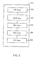
- the program code 214 includes program code of multiple communications protocol layers, which from top to bottom are a radio resource control (RRC) layer 300, a packet data convergence protocol (PDCP) layer 310, a radio link control (RLC) layer 320, a medium access control (MAC) layer 330 and a physical (PHY) layer 340.
- RRC radio resource control
- PDCP packet data convergence protocol
- RLC radio link control
- MAC medium access control
- PHY physical
- the MAC layer 330 is capable of performing various functions, such as packet transfer, discontinuous reception (DRX), power headroom reporting, buffer status reporting, TTI (Transmission Time Interval) bundling etc. Accordingly, the RRC layer 300 employs an "MAC-MainConfiguration” information element (IE) to configure/reconfigure the MAC layer 330.
- the "MAC-MainConfiguration” IE can be generated by the RRC layer 300 or the network. If the "MAC-MainConfiguration” IE is generated by the network, the "MAC-MainConfiguration” IE can be included in a RRC CONNECTION RECONFIGURATION message used as dedicated signaling and then sent to the communication device 20.
- the communication device 20 when the RRC layer 300 receives a RRC CONNECTION RECONFIGURATION message including a mobilitycontrollnformation IE, the communication device 20 is directed to perform a handover procedure.
- the mobilityControlInformation IE is considered a handover-featured IE.
- the "MAC-MainConfiguration" includes configuration of a DL-SCH (Downlink Shared Channel), a UL-SCH (Uplink Shared Channel), the DRX function, the power headroom reporting function, and the buffer status reporting function, and thereby has various timers, such as a time alignment timer, a periodicBSR timer, an onduration timer, etc.
- a process is provided as below to prevent errors in the MAC layer caused by enforcement of a timer value change.
- Fig. 4 illustrates a flowchart of a process 40 according to an embodiment of the present invention.
- the process 40 is utilized for reconfiguring MAC parameters for a UE of a wireless communication system.
- the process 40 can be compiled into the program code 214 and includes the following steps:
- the UE when the timer has been running and the UE receives the RRC dedicated signaling including the change value, the UE starts to use the change value at next time the timer is started or restarted. That is, after the timer expires and is started to run again, the change value is applied for the timer.
- the UE does not immediately change the value of the running timer, and therefore unexpected system errors are avoided.
- the RRC dedicated signaling is a RRC CONNECTION RECONFIGURATION message including a "MAC-MainConfiguration” information element (IE).
- IE MAC-MainConfiguration
- Fig. 5 illustrates a flowchart of a process 50 according to an embodiment of the present invention.
- the process 50 is utilized for reconfiguring MAC parameters for a UE of a wireless communication system.
- the process 50 can be compiled into the program code 214 and includes the following steps:
- the UE determines whether to continue the running of the timer or to restart the timer according to the change value, the current value and the expiry value when the change value included in the RRC dedicated signaling is received during the running of the timer.
- the current value is the value of the timer obtained when the change value is received; the expiry value is the value at which the timer stops running.
- FIG. 6 illustrates a flowchart of a process 60 according to an embodiment of the present invention.
- the process 60 is used for determining whether to continue the running of the timer or to restart the timer and includes the following steps:
- the UE continues the running of the timer when x is larger than or equal to y, restarts the timer with (x-(y-z)) when x is smaller than y and larger than (y-z), and restarts the timer with x when x is smaller than or equal to (y-z).
- the UE further starts/restarts the timer with x when next opportunity of starting/restarting the timer occurs.
- the UE When x is larger than y, the UE does not immediately change the timer to x and thereby avoids an erroneous situation that the current value of the timer is larger than the expiry value.
- (y-z) means a left time of the timer to expiry.
- the timer is reconfigured to an extent count time compared to the original total count time through Steps 650-660. Through the process 60, the running timer is properly reconfigured to avoid system errors.
- Fig. 7 illustrates a flowchart of a process 70 according to an embodiment of the present invention.
- the process 70 is utilized for reconfiguring MAC parameters for a UE of a wireless communication system.
- the process 70 can be compiled into the program code 214 and includes the following steps:
- the UE stops the running timer when the RRC dedicated signaling with the "infinity” change value is received. Since the "infinity" change value can cause severe system errors if the timer is immediately reconfigured to the "infinity” change value, the UE stops the timer to avoid the system errors.
- the "infinity" change value is a predetermined value or character.
- the RRC dedicated signaling is the RRC CONNECTION RECONFIGURATION message including the "MAC-MainConfiguration" IE.
- the UE mainly determines how to deal with the MAC parameter according to the change value.
- the DRX function of the MAC layer has short and long cycle modes.
- a Short DRX cycle timer is used for providing a time length in which the UE shall perform the short cycle mode. That is, running of the Short DRX cycle timer means that the short cycle mode is activated.
- following processes are provided to prevent DRX operation errors.
- Fig. 8 illustrates a flowchart of a process 80 according to an embodiment of the present invention.
- the process 80 is utilized for reconfiguring MAC DRX parameters for a UE of a wireless communication system.
- the process 80 can be compiled into the program code 214 and includes the following steps:
- the UE stops both the short DRX cycle and the Short DRX cycle Timer when the RRC dedicated signaling for disabling a short cycle mode is received and the short cycle mode is in-use. Furthermore, the UE can start to use the long cycle mode (e.g. employing a DRX long cycle) after the short cycle mode is deactivated, more specifically at next cycle after the short cycle mode is deactivated. The UE can further stop the Short DRX cycle Timer to deactivate the short cycle mode.
- the long cycle mode e.g. employing a DRX long cycle
- Fig. 9 illustrates a flowchart of a process 90 according to an embodiment of the present invention.
- the process 90 is utilized for reconfiguring MAC DRX parameters for a UE of a wireless communication system.
- the process 90 can be compiled into the program code 214 and includes the following steps:
- the UE receives the RRC dedicated signaling during the activation of the short cycle mode, and waits for expiry of the Short DRX cycle timer. After the Short DRX cycle timer expires, this means that the short cycle mode is deactivated, and the UE starts to use the long cycle mode from next DRX cycle. Through the process 90, the UE can avoid a sudden interruption of the short cycle mode.
- the UE starts to use the long cycle mode from next DRX cycle by applying a long DRX cycle for next DRX cycle.
- Step 920 can be replaced by a step of starting to use the long cycle mode immediately when a DRX Command MAC control element is received from the network. Since the DRX Command MAC control element directly corresponds to MAC DRX operation, the long cycle mode shall be immediately applied.
- FIG. 10 illustrates a flowchart of a process 1000 according to an embodiment of the present invention.
- the process 1000 is utilized for reconfiguring MAC DRX parameters for a UE of a wireless communication system.
- the process 1000 can be compiled into the program code 214 and includes the following steps:
- the UE extends an in-use DRX cycle to the long DRX cycle when the RRC dedicated signaling is received during activation of the short cycle mode.
- the process 1000 can be also applied when starting subframe numbers for the short and long DRX cycles are the same.
- the RRC dedicated signaling for disabling a short cycle mode can be the RRC CONNECTION RECONFIGURATION message including the "MAC-MainConfiguration", and a short DRX parameter of the "MAC-MainConfiguration" IE is set to 'disable'.
- FIG. 11 illustrates a flowchart of a process 1100 according to an embodiment of the present invention.
- the process 1100 is utilized for reconfiguring MAC DRX parameters for a UE of a wireless communication system.
- the process 1100 can be compiled into the program code 214 and includes the following steps:
- the UE starts to use the change value for the DRX cycle length/DRX cycle start offset from next DRX cycle when the change value of a DRX cycle length/DRX cycle start offset is received during activation of the DRX operation.
- the UE does not immediately reconfigure the current DRX cycle length/DRX cycle start offset to the change value during current DRX cycle, thereby avoiding unexpected system errors.
- Fig. 12 illustrates a flowchart of a process 1200 according to an embodiment of the present invention.
- the process 1200 is utilized for reconfiguring MAC DRX parameters for a UE of a wireless communication system.
- the process 1200 can be compiled into the program code 214 and includes the following steps:
- the UE stops the on-going DRX cycle and starts a new DRX cycle with the change value for the DRX cycle length/DRX cycle start offset when the change value is received during activation of the DRX operation. Therefore, the UE does not directly apply the change value for the on-going DRX cycle, thereby avoiding unexpected system errors.
- the RRC dedicated signaling can be the RRC CONNECTION RECONFIGURATION message including the "MAC-MainConfiguration"
- Fig. 13 illustrates a flowchart of a process 1300 according to an embodiment of the present invention.
- the process 1300 is utilized for reconfiguring MAC DRX parameters for a UE of a wireless communication system.
- the process 1300 can be compiled into the program code 214 and includes the following steps:
- the UE considers that the RRC dedicated signaling is invalid when the RRC dedicated signaling that does not include the handover-featured IE is received.
- the handover-featured IE can trigger a reset of the MAC layer, and therefore system errors can be avoided when the UE applies the MAC parameters reconfiguration included in the RRC dedicated signaling immediately after the reset of the MAC layer.
- the RRC dedicated signaling for reconfiguring the MAC parameters is a RRC CONNECTION RECONFIGURATION message;
- the handover-featured IE is a mobilitycontrollnformation IE.
- the UE further determines that a reconfiguration failure occurs and performs a RRC connection reestablishment procedure to recover the reconfiguration failure.
- the processes 40, 1100-1200 provide a method of starting to apply the reconfiguration of the parameter at next opportunity corresponding to the parameter when the RRC dedicated signaling for reconfiguration of the parameter is received during use of the parameter.
- the UE mainly determines how to deal with the MAC parameter according to the change value.
- the UE mainly switches from the short cycle mode to the long cycle mode with/without substantial stopping operation of the short cycle mode when the RRC dedicated signaling for disabling the short cycle mode is received during the activation of the short cycle mode.
- the embodiments of the present invention do not immediately apply a reconfigured value for an in-use MAC parameter (e.g. a timer), and for the DRX operation, properly stop the short cycle mode and switch to the long cycle mode. Therefore, unexpected system errors in the MAC operation can be avoided.
- an in-use MAC parameter e.g. a timer
Landscapes
- Engineering & Computer Science (AREA)
- Computer Networks & Wireless Communication (AREA)
- Signal Processing (AREA)
- Mobile Radio Communication Systems (AREA)
Abstract
Description
- The present invention relates to a method for reconfiguring parameters of a medium access control (MAC) layer in a wireless communication system according to the pre-characterizing clauses of independent claims.
- A long-term evolution (LTE) system, initiated by the third generation partnership project (3GPP), is now being regarded as a new radio interface and radio network architecture that provides a high data rate, low latency, packet optimization, and improved system capacity and coverage. In the LTE system, an evolved universal terrestrial radio access network (E-UTRAN) includes a plurality of evolved Node-Bs (eNBs) and communicates with a plurality of mobile stations, also referred as user equipments (UEs).
- A radio interface protocol of the LTE system includes three layers: the Physical Layer (L1), the Data Link Layer (L2), and the Network Layer (L3), wherein a control plane of L3 is a Radio Resource Control (RRC) layer, and L2 is further divided into a Packet Data Convergence Protocol (PDCP) layer, a Radio Link Control (RLC) layer and a Medium Access Control (MAC) layer.
- Main services and functions of the MAC layer include mapping between logical channels and transport channels; multiplexing/demultiplexing of PDUs (Packet Data Units) belonging to one or different radio bearers into/from transport blocks (TBs) delivered to/from the physical layer on transport channels; buffer status reporting; power headroom reporting; error correction through HARQ; priority handling between logical channels of one UE; discontinuous reception (DRX); priority handling between UEs by means of dynamic scheduling; and padding.
- Various MAC parameters, such as timers and counters, are employed for the abovementioned functions/services and are configured or reconfigured by the RRC layer. In RRC (re)configuration, the MAC parameters are grouped into a "MAC-MainConfiguration" information element (IE). When the MAC parameters of the UE are reconfigured by the RRC layer of the EUTRAN, two ways are used for reconfiguration of MAC parameters. In the first way, the UE receives the MAC parameters from broadcasted system information and then receives MAC parameters from dedicated RRC signaling, e.g. a RRC CONNECTION RECONFIGURATION message. In the second way, the UE only receives the MAC parameters from dedicated RRC signaling, e.g. a RRC CONNECTION RECONFIGURATION message.
- In DRX parameters of the "MAC-MainConfiguration" IE, a short DRX parameter has choices of 'disable', 'NULL', and 'enable'. When the short DRX parameter is set to 'disable', a short DRX cycle is possibly still configured with a value, and thereby the short DRX parameter is not substantially disabled, but only nominally. This causes a system error.
- The MAC parameters may be reconfigured when they are in use. According to the prior art, the reconfigured MAC parameters is required to be applied immediately. For example, a timer value is received for reconfiguration of a currently-running timer. The timer is immediately restarted with the reconfigured timer value. However, enforcing a newly-reconfigured value on an in-use MAC parameter can cause errors of corresponding function/system or impact communication system performance.
- This in mind, the present invention aims at providing a method for reconfiguring parameters of a MAC layer in a wireless communication system to solve the abovementioned problems.
- This is achieved by a method, a communication device and a computer program product for reconfiguring a parameter of a MAC layer for a mobile device of a wireless communication system according to claims 1, 5 and 6. The dependent claims pertain to corresponding further developments and improvements.
- As will be seen more clearly from the detailed description following below, the claimed method for reconfiguring a parameter of a MAC layer for a mobile device of a wireless communication system includes when a RRC dedicated signaling for reconfiguration of the parameter is received during activation of the parameter, starting to apply the reconfiguration of the parameter at next opportunity corresponding to the parameter.
- In the following, the invention is further illustrated by way of example, taking reference to the accompanying drawings. Thereof
-
Fig. 1 is a schematic diagram of a wireless communication system, -
Fig. 2 is a schematic diagram of a communication device according to an embodiment of the present invention, -
Fig. 3 is a schematic diagram of multiple communications protocol layers, and -
Figs. 4-13 are flowcharts of processes according to embodiments of the present invention. - Please refer to
Fig. 1 , which illustrates a schematic diagram of awireless communication system 10 according to an embodiment of the present invention. Briefly, thewireless communication system 10 is composed of a network and a plurality of mobile devices. InFig. 1 , the network and the mobile devices are simply utilized for illustrating the structure of thewireless communication system 10. Thewireless communication system 10 can be a UMTS (Universal Mobile Telecommunications System) or an LTE (long-term evolution) system. In the LTE system, the network is referred as a EUTRAN (evolved-UTRAN) comprising a plurality of eNBs, whereas the mobile devices are referred as user equipments (UEs). The UEs can be devices such as mobile phones, computer systems, etc. Besides, the network and the UE can be seen as a transmitter or receiver according to transmission direction, e.g., for uplink (UL), the UE is the transmitter and the network is the receiver, and for downlink (DL), the network is the transmitter and the UE is the receiver. - Please refer to
Fig. 2 , which illustrates a schematic diagram of acommunication device 20 according to an embodiment of the present invention. Thecommunication device 20 can be the mobile devices shown inFig. 1 and includes aprocessor 200, a computerreadable recording medium 210 and acommunication interfacing unit 220. The computerreadable recording medium 210 is any data storage device that includesprogram code 214, thereafter read and processed by theprocessor 200. Examples of the computerreadable recording medium 210 include a subscriber identity module (SIM), read-only memory (ROM), random-access memory (RAM), CD-ROMs, magnetic tapes, hard disks, optical data storage devices, and carrier waves (such as data transmission through the Internet). Thecommunication interfacing unit 220 is preferably a radio transceiver and accordingly exchanges wireless signals with the network. - Please refer to
Fig. 3 , which illustrates a schematic diagram of multiple communications protocol layers of the LTE system applied by theprogram code 214 according to an embodiment of the present invention. Theprogram code 214 includes program code of multiple communications protocol layers, which from top to bottom are a radio resource control (RRC)layer 300, a packet data convergence protocol (PDCP)layer 310, a radio link control (RLC)layer 320, a medium access control (MAC)layer 330 and a physical (PHY)layer 340. - The
MAC layer 330 is capable of performing various functions, such as packet transfer, discontinuous reception (DRX), power headroom reporting, buffer status reporting, TTI (Transmission Time Interval) bundling etc. Accordingly, theRRC layer 300 employs an "MAC-MainConfiguration" information element (IE) to configure/reconfigure theMAC layer 330. The "MAC-MainConfiguration" IE can be generated by theRRC layer 300 or the network. If the "MAC-MainConfiguration" IE is generated by the network, the "MAC-MainConfiguration" IE can be included in a RRC CONNECTION RECONFIGURATION message used as dedicated signaling and then sent to thecommunication device 20. In addition, when theRRC layer 300 receives a RRC CONNECTION RECONFIGURATION message including a mobilitycontrollnformation IE, thecommunication device 20 is directed to perform a handover procedure. The mobilityControlInformation IE is considered a handover-featured IE. - The "MAC-MainConfiguration" includes configuration of a DL-SCH (Downlink Shared Channel), a UL-SCH (Uplink Shared Channel), the DRX function, the power headroom reporting function, and the buffer status reporting function, and thereby has various timers, such as a time alignment timer, a periodicBSR timer, an onduration timer, etc.
- When any of the abovementioned timers has been activated to run, a process is provided as below to prevent errors in the MAC layer caused by enforcement of a timer value change. Please refer to
Fig. 4 , which illustrates a flowchart of aprocess 40 according to an embodiment of the present invention. Theprocess 40 is utilized for reconfiguring MAC parameters for a UE of a wireless communication system. Theprocess 40 can be compiled into theprogram code 214 and includes the following steps: - Step 400: : Start.
- Step 410: : When a RRC dedicated signaling including a change value of a timer is received during running of the timer, start to use the change value at next time the timer is started or restarted.
- Step 420: : End.
- According to the
process 40, when the timer has been running and the UE receives the RRC dedicated signaling including the change value, the UE starts to use the change value at next time the timer is started or restarted. That is, after the timer expires and is started to run again, the change value is applied for the timer. Through theprocess 40, the UE does not immediately change the value of the running timer, and therefore unexpected system errors are avoided. - Preferably, the RRC dedicated signaling is a RRC CONNECTION RECONFIGURATION message including a "MAC-MainConfiguration" information element (IE).
- Please refer to
Fig. 5 , which illustrates a flowchart of aprocess 50 according to an embodiment of the present invention. Theprocess 50 is utilized for reconfiguring MAC parameters for a UE of a wireless communication system. Theprocess 50 can be compiled into theprogram code 214 and includes the following steps: - Step 500: : Start.
- Step 510: : When a RRC dedicated signaling including a change value of a timer is received during running of the timer, determine whether to continue the running of the timer or to restart the timer according to the change value, a current value of the timer, and an expiry value of the timer related to the running of the timer.
- Step 520: : End.
- According to the
process 50, the UE determines whether to continue the running of the timer or to restart the timer according to the change value, the current value and the expiry value when the change value included in the RRC dedicated signaling is received during the running of the timer. The current value is the value of the timer obtained when the change value is received; the expiry value is the value at which the timer stops running. - Another embodiment based on the concept of the
process 50 is provided as follows. Assume that the current value is z, the expiry value is y, and the change value is x. In addition, the timer performs increasing time counting and thereby y is larger than z. Please refer toFig. 6 , which illustrates a flowchart of aprocess 60 according to an embodiment of the present invention. Theprocess 60 is used for determining whether to continue the running of the timer or to restart the timer and includes the following steps: - Step 600: : Start.
- Step 610: : Obtain x, y, and z.
- Step 620: : Determine whether x is smaller than y? If so, perform
Step 630, else performStep 640. - Step 630: : Determine whether x is larger than (y-z)? If so, perform
Step 650, else performStep 660. - Step 640: : Continue the running of the timer and then perform
Step 670. - Step 650: : Restart the timer with (x-(y-z)) and then perform
Step 670. - Step 660: : Restart the timer with x.
- Step 670: : End.
- As can be seen from the
process 60, the UE continues the running of the timer when x is larger than or equal to y, restarts the timer with (x-(y-z)) when x is smaller than y and larger than (y-z), and restarts the timer with x when x is smaller than or equal to (y-z). At any expiry of Steps 640-660, the UE further starts/restarts the timer with x when next opportunity of starting/restarting the timer occurs. - When x is larger than y, the UE does not immediately change the timer to x and thereby avoids an erroneous situation that the current value of the timer is larger than the expiry value. (y-z) means a left time of the timer to expiry. As a result, the timer is reconfigured to an extent count time compared to the original total count time through Steps 650-660. Through the
process 60, the running timer is properly reconfigured to avoid system errors. - Please refer to
Fig. 7 , which illustrates a flowchart of aprocess 70 according to an embodiment of the present invention. Theprocess 70 is utilized for reconfiguring MAC parameters for a UE of a wireless communication system. Theprocess 70 can be compiled into theprogram code 214 and includes the following steps: - Step 700: : Start.
- Step 710: : When a RRC dedicated signaling including a change value of a timer is received during running of the timer and the change value represents "infinity", stop the timer.
- Step 720: : End.
- According to the
process 70, the UE stops the running timer when the RRC dedicated signaling with the "infinity" change value is received. Since the "infinity" change value can cause severe system errors if the timer is immediately reconfigured to the "infinity" change value, the UE stops the timer to avoid the system errors. - Preferably, the "infinity" change value is a predetermined value or character. The RRC dedicated signaling is the RRC CONNECTION RECONFIGURATION message including the "MAC-MainConfiguration" IE.
- In the processes 50-70, the UE mainly determines how to deal with the MAC parameter according to the change value.
- The DRX function of the MAC layer has short and long cycle modes. In the short cycle mode, a Short DRX cycle timer is used for providing a time length in which the UE shall perform the short cycle mode. That is, running of the Short DRX cycle timer means that the short cycle mode is activated. In this situation, following processes are provided to prevent DRX operation errors. Please refer to
Fig. 8 , which illustrates a flowchart of aprocess 80 according to an embodiment of the present invention. Theprocess 80 is utilized for reconfiguring MAC DRX parameters for a UE of a wireless communication system. Theprocess 80 can be compiled into theprogram code 214 and includes the following steps: - Step 800: : Start.
- Step 810: : When a RRC dedicated signaling for disabling a short cycle mode is received during activation of the short cycle mode, stop both a short DRX cycle and a Short DRX cycle Timer.
- Step 820: : End.
- According to the
process 80, the UE stops both the short DRX cycle and the Short DRX cycle Timer when the RRC dedicated signaling for disabling a short cycle mode is received and the short cycle mode is in-use. Furthermore, the UE can start to use the long cycle mode (e.g. employing a DRX long cycle) after the short cycle mode is deactivated, more specifically at next cycle after the short cycle mode is deactivated. The UE can further stop the Short DRX cycle Timer to deactivate the short cycle mode. - Please refer to
Fig. 9 , which illustrates a flowchart of aprocess 90 according to an embodiment of the present invention. Theprocess 90 is utilized for reconfiguring MAC DRX parameters for a UE of a wireless communication system. Theprocess 90 can be compiled into theprogram code 214 and includes the following steps: - Step 900: : Start.
- Step 910: : Receive a RRC dedicated signaling for disabling a short cycle mode during activation of the short cycle mode.
- Step 920: : Start to use a long cycle mode from next DRX cycle after a Short DRX cycle timer expires.
- Step 930: : End.
- According to the
process 90, the UE receives the RRC dedicated signaling during the activation of the short cycle mode, and waits for expiry of the Short DRX cycle timer. After the Short DRX cycle timer expires, this means that the short cycle mode is deactivated, and the UE starts to use the long cycle mode from next DRX cycle. Through theprocess 90, the UE can avoid a sudden interruption of the short cycle mode. - Preferably, the UE starts to use the long cycle mode from next DRX cycle by applying a long DRX cycle for next DRX cycle.
- Alternatively, Step 920 can be replaced by a step of starting to use the long cycle mode immediately when a DRX Command MAC control element is received from the network. Since the DRX Command MAC control element directly corresponds to MAC DRX operation, the long cycle mode shall be immediately applied.
- Please refer to
Fig. 10 , which illustrates a flowchart of a process 1000 according to an embodiment of the present invention. The process 1000 is utilized for reconfiguring MAC DRX parameters for a UE of a wireless communication system. The process 1000 can be compiled into theprogram code 214 and includes the following steps: - Step 1010: : Start.
- Step 1020: : When a RRC dedicated signaling for disabling a short cycle mode is received during activation of the short cycle mode, extend an in-use DRX cycle to a long DRX cycle of the long cycle mode.
- Step 1030: : End.
- According to the process 1000, the UE extends an in-use DRX cycle to the long DRX cycle when the RRC dedicated signaling is received during activation of the short cycle mode. The process 1000 can be also applied when starting subframe numbers for the short and long DRX cycles are the same.
- In the
process - Please refer to
Fig. 11 , which illustrates a flowchart of a process 1100 according to an embodiment of the present invention. The process 1100 is utilized for reconfiguring MAC DRX parameters for a UE of a wireless communication system. The process 1100 can be compiled into theprogram code 214 and includes the following steps: - Step 1110: : Start.
- Step 1120: : When a RRC dedicated signaling indicating a change value of a DRX cycle length/DRX cycle start offset is received during activation of the DRX operation, start to use the change value for the DRX cycle length/DRX cycle start offset from next DRX cycle.
- Step 1130: : End.
- According to the process 1100, the UE starts to use the change value for the DRX cycle length/DRX cycle start offset from next DRX cycle when the change value of a DRX cycle length/DRX cycle start offset is received during activation of the DRX operation. In other words, the UE does not immediately reconfigure the current DRX cycle length/DRX cycle start offset to the change value during current DRX cycle, thereby avoiding unexpected system errors.
- Please refer to
Fig. 12 , which illustrates a flowchart of a process 1200 according to an embodiment of the present invention. The process 1200 is utilized for reconfiguring MAC DRX parameters for a UE of a wireless communication system. The process 1200 can be compiled into theprogram code 214 and includes the following steps: - Step 1210: : Start.
- Step 1220: : When a RRC dedicated signaling indicating a change value of a DRX cycle length/DRX cycle start offset is received during activation of the DRX operation, stop an on-going DRX cycle and starts a DRX cycle with the change value for the DRX cycle length/DRX cycle start offset.
- Step 1230: : End.
- According to the process 1200, the UE stops the on-going DRX cycle and starts a new DRX cycle with the change value for the DRX cycle length/DRX cycle start offset when the change value is received during activation of the DRX operation. Therefore, the UE does not directly apply the change value for the on-going DRX cycle, thereby avoiding unexpected system errors.
- In the process 1100 and 1200, the RRC dedicated signaling can be the RRC CONNECTION RECONFIGURATION message including the "MAC-MainConfiguration"
- Please refer to
Fig. 13 , which illustrates a flowchart of a process 1300 according to an embodiment of the present invention. The process 1300 is utilized for reconfiguring MAC DRX parameters for a UE of a wireless communication system. The process 1300 can be compiled into theprogram code 214 and includes the following steps: - Step 1310: : Start.
- Step 1320: : When a RRC dedicated signaling for reconfiguring MAC parameters is received and does not include a handover-featured information element (IE) triggering a MAC reset, determine that the RRC dedicated signaling is invalid.
- Step 1330: : End.
- According to the process 1300, the UE considers that the RRC dedicated signaling is invalid when the RRC dedicated signaling that does not include the handover-featured IE is received. The handover-featured IE can trigger a reset of the MAC layer, and therefore system errors can be avoided when the UE applies the MAC parameters reconfiguration included in the RRC dedicated signaling immediately after the reset of the MAC layer.
- Preferably, the RRC dedicated signaling for reconfiguring the MAC parameters is a RRC CONNECTION RECONFIGURATION message; the handover-featured IE is a mobilitycontrollnformation IE. In this situation, the UE further determines that a reconfiguration failure occurs and performs a RRC connection reestablishment procedure to recover the reconfiguration failure.
- As can be seen from the above, the
processes 40, 1100-1200 provide a method of starting to apply the reconfiguration of the parameter at next opportunity corresponding to the parameter when the RRC dedicated signaling for reconfiguration of the parameter is received during use of the parameter. In the processes 50-70, the UE mainly determines how to deal with the MAC parameter according to the change value. In theprocesses - In conclusion, the embodiments of the present invention do not immediately apply a reconfigured value for an in-use MAC parameter (e.g. a timer), and for the DRX operation, properly stop the short cycle mode and switch to the long cycle mode. Therefore, unexpected system errors in the MAC operation can be avoided.
Claims (6)
- A method for reconfiguring parameters of a discontinuous reception, hereinafter called DRX, operation of a medium access control layer (330) for a mobile device (20) of a wireless communication system (10), characterized by the method comprising:when a radio resource control dedicated signaling for disabling a short cycle mode of the discontinuous reception operation is received during activation of the short cycle mode, switching from the short cycle mode to a long cycle mode of the discontinuous reception operation.
- The method of claim 1, characterized by stopping a short DRX cycle of the short cycle mode when the radio resource control dedicated signaling for disabling the short cycle mode of the discontinuous reception operation is received during the activation of the short cycle mode.
- The method of claim 2, characterized by stopping a Short DRX cycle Timer of the short cycle mode.
- The method of any one of claims 1 to 3, characterized in that switching from the short cycle mode to the long cycle mode of the discontinuous reception operation comprises:starting to use the long cycle mode from the next DRX cycle after a Short DRX cycle timer of the short cycle mode expires,starting to use the long cycle mode immediately when a DRX command control element for the medium access control layer is received from the network, orextending an in-use DRX cycle to a long DRX cycle of the long cycle mode.
- A computer program product, comprising computer program code (214) configured to perform any of the preceding methods 1 to 4 when executed.
- A communication device (20), comprising:a processor (200);a computer readable recording medium (210) configured to store the computer program product of the claim 5, processed by the processor.
Applications Claiming Priority (2)
| Application Number | Priority Date | Filing Date | Title |
|---|---|---|---|
| US11095108P | 2008-11-03 | 2008-11-03 | |
| EP09013827A EP2182765A3 (en) | 2008-11-03 | 2009-11-03 | Method for parameter reconfiguration in a wireless communications system |
Related Parent Applications (1)
| Application Number | Title | Priority Date | Filing Date |
|---|---|---|---|
| EP09013827A Division EP2182765A3 (en) | 2008-11-03 | 2009-11-03 | Method for parameter reconfiguration in a wireless communications system |
Publications (2)
| Publication Number | Publication Date |
|---|---|
| EP2506647A1 true EP2506647A1 (en) | 2012-10-03 |
| EP2506647B1 EP2506647B1 (en) | 2014-07-16 |
Family
ID=41682491
Family Applications (2)
| Application Number | Title | Priority Date | Filing Date |
|---|---|---|---|
| EP09013827A Withdrawn EP2182765A3 (en) | 2008-11-03 | 2009-11-03 | Method for parameter reconfiguration in a wireless communications system |
| EP12172667.3A Active EP2506647B1 (en) | 2008-11-03 | 2009-11-03 | Method for parameter reconfiguration in a wireless communications system |
Family Applications Before (1)
| Application Number | Title | Priority Date | Filing Date |
|---|---|---|---|
| EP09013827A Withdrawn EP2182765A3 (en) | 2008-11-03 | 2009-11-03 | Method for parameter reconfiguration in a wireless communications system |
Country Status (4)
| Country | Link |
|---|---|
| US (2) | US8315182B2 (en) |
| EP (2) | EP2182765A3 (en) |
| CN (2) | CN102325379B (en) |
| TW (1) | TWI419593B (en) |
Families Citing this family (31)
| Publication number | Priority date | Publication date | Assignee | Title |
|---|---|---|---|---|
| US8750218B2 (en) * | 2008-09-29 | 2014-06-10 | Blackberry Limited | Message processing in communication systems |
| CN102217397B (en) | 2008-09-29 | 2015-08-26 | 黑莓有限公司 | The uplink resynchronization used in a communications system |
| CN101742618B (en) * | 2008-11-14 | 2013-04-24 | 华为技术有限公司 | Method and base station for determining discontinuous transmission mode |
| US8743896B2 (en) * | 2009-03-16 | 2014-06-03 | Htc Corporation | Method and related communication device for radio link control reconfiguration in a wireless communications system |
| US8817681B2 (en) * | 2009-04-20 | 2014-08-26 | Panasonic Intellectual Property Corporation Of America | Wireless communication apparatus and wireless communication method using a gap pattern |
| WO2011042869A1 (en) * | 2009-10-05 | 2011-04-14 | Nokia Corporation | Preventing mac activation with incorrect parameters during handover |
| CN102300321B (en) * | 2010-06-23 | 2015-07-22 | 电信科学技术研究院 | Power headroom reporting (PHR) method, system and device in multicarrier polymerization system |
| JP2012124603A (en) * | 2010-12-06 | 2012-06-28 | Sony Corp | Communication system and communication device |
| JP5720215B2 (en) * | 2010-12-06 | 2015-05-20 | ソニー株式会社 | Gateway apparatus and communication method |
| KR102247818B1 (en) | 2011-08-10 | 2021-05-04 | 삼성전자 주식회사 | Method and apparatus for transmitting data in mobile communication system with multiple carrier |
| KR101967721B1 (en) | 2011-08-10 | 2019-04-10 | 삼성전자 주식회사 | Method and appratus of applying extended access barring in mobile communication system |
| EP3429307B1 (en) | 2011-08-10 | 2022-06-15 | Samsung Electronics Co., Ltd. | Method and apparatus for transmitting data using a multi-carrier in a mobile communication system |
| KR101990134B1 (en) | 2011-08-10 | 2019-06-17 | 삼성전자주식회사 | Method and apparatus for reporting capability information of dual mode user equipment |
| US10321419B2 (en) * | 2011-08-10 | 2019-06-11 | Samsung Electronics Co., Ltd. | Method and apparatus for transmitting data using a multi-carrier in a mobile communication system |
| KR102092579B1 (en) | 2011-08-22 | 2020-03-24 | 삼성전자 주식회사 | Method and apparatus for support multiple frequency band in a mobile communication system |
| CN103139920B (en) | 2011-11-24 | 2016-06-29 | 华为技术有限公司 | A kind of method for discontinuous reception configuration and subscriber equipment |
| EP2621242A1 (en) | 2012-01-26 | 2013-07-31 | Panasonic Corporation | Improved discontinuous reception operation with additional wake up opportunities |
| US9414409B2 (en) | 2012-02-06 | 2016-08-09 | Samsung Electronics Co., Ltd. | Method and apparatus for transmitting/receiving data on multiple carriers in mobile communication system |
| CN103260225B (en) * | 2012-02-20 | 2017-04-26 | 华为技术有限公司 | Discontinuous reception (DRX) control method and device |
| CN104620515B (en) | 2012-11-29 | 2018-02-16 | Lg电子株式会社 | Method and apparatus for the DRX operations in radio communication |
| US9565631B2 (en) | 2013-01-18 | 2017-02-07 | Telefonaktiebolaget Lm Ericsson (Publ) | Method and arrangement for controlling discontinuous reception by a user equipment |
| WO2014112918A1 (en) * | 2013-01-18 | 2014-07-24 | Telefonaktiebolaget L M Ericsson (Publ) | Method and arrangement in a telecommunication system |
| CN104066113A (en) * | 2013-03-21 | 2014-09-24 | 中兴通讯股份有限公司 | Method and apparatus for sending power headroom report |
| US10542450B2 (en) * | 2013-09-30 | 2020-01-21 | Alcatel-Lucent Usa, Inc | Techniques for improving discontinuous reception in wideband wireless networks |
| TWI484850B (en) * | 2013-11-14 | 2015-05-11 | Univ Nat Chiao Tung | Power-saving data scheduling system in lte and method thereof |
| GB2537181A (en) * | 2015-04-10 | 2016-10-12 | Nec Corp | Communication system |
| US10609758B2 (en) | 2016-08-12 | 2020-03-31 | Motorola Mobility Llc | Methods, devices, and systems for discontinuous reception for a shortened transmission time interval and processing time |
| CN108632884B (en) * | 2017-03-17 | 2020-06-30 | 维沃移动通信有限公司 | Reconfiguration method and device of buffer status report timer |
| GB2563584B (en) * | 2017-06-16 | 2022-05-04 | Tcl Communication Ltd | Bearer control |
| CN111436165B (en) * | 2019-03-27 | 2022-06-03 | 维沃移动通信有限公司 | Information configuration method, network equipment and terminal equipment |
| CN111955049B (en) * | 2020-06-24 | 2023-12-22 | 北京小米移动软件有限公司 | State control method, device, communication equipment and storage medium |
Citations (1)
| Publication number | Priority date | Publication date | Assignee | Title |
|---|---|---|---|---|
| US20070291728A1 (en) * | 2006-06-20 | 2007-12-20 | Lars Dalsgaard | Method and system for providing interim discontinuous reception/transmission |
Family Cites Families (15)
| Publication number | Priority date | Publication date | Assignee | Title |
|---|---|---|---|---|
| DE60311574T2 (en) * | 2003-08-14 | 2007-11-15 | Matsushita Electric Industrial Co., Ltd., Kadoma | Time monitoring of packet re-transmissions during a soft handoff |
| GB2447299A (en) * | 2007-03-09 | 2008-09-10 | Nec Corp | Control of discontinuous Rx/Tx in a mobile communication system |
| US20080232310A1 (en) * | 2007-03-19 | 2008-09-25 | Shugong Xu | Flexible user equipment-specified discontinuous reception |
| EP2144452A1 (en) * | 2007-04-24 | 2010-01-13 | NTT DoCoMo, Inc. | Mobile communication method, wireless base station, mobile station, and processor |
| WO2008133310A1 (en) * | 2007-04-24 | 2008-11-06 | Ntt Docomo, Inc. | Mobile communication method and radio base station |
| US8023467B2 (en) * | 2007-04-27 | 2011-09-20 | Research In Motion Limited | Method and system for efficient DRX operation during handover in LTE |
| KR20080097338A (en) * | 2007-05-01 | 2008-11-05 | 엘지전자 주식회사 | Discontinuous data transmittion/reception method |
| AU2007353893B2 (en) * | 2007-05-23 | 2011-01-27 | Telefonaktiebolaget Lm Ericsson (Publ) | Method and arrangement for reducing battery power consumption of a user equipment |
| KR101441138B1 (en) * | 2007-09-28 | 2014-09-18 | 엘지전자 주식회사 | Method of performing uplink time alignment in wireless communication system |
| KR101514079B1 (en) * | 2008-01-07 | 2015-04-21 | 엘지전자 주식회사 | Method for reconfiguring time alignment timer |
| JP4991942B2 (en) * | 2008-01-17 | 2012-08-08 | テレフオンアクチーボラゲット エル エム エリクソン(パブル) | Method and arrangement for processing a wireless receiver in a wireless communication network |
| US20090253470A1 (en) * | 2008-04-02 | 2009-10-08 | Shugong Xu | Control of user equipment discontinuous reception setting via mac lcid |
| KR101206084B1 (en) * | 2008-04-25 | 2012-11-28 | 리서치 인 모션 리미티드 | Method and system for the control of discontinuous reception in a wireless network |
| US8489950B2 (en) * | 2008-08-06 | 2013-07-16 | Nokia Siemens Networks Oy | Discontinuous reception retransmission timer and method |
| US8625486B2 (en) * | 2008-08-08 | 2014-01-07 | Interdigital Patent Holdings, Inc. | MAC reset and reconfiguration |
-
2009
- 2009-10-26 US US12/605,385 patent/US8315182B2/en active Active
- 2009-11-02 TW TW098137114A patent/TWI419593B/en active
- 2009-11-03 CN CN201110340774.5A patent/CN102325379B/en active Active
- 2009-11-03 CN CN200910221027A patent/CN101730152A/en active Pending
- 2009-11-03 EP EP09013827A patent/EP2182765A3/en not_active Withdrawn
- 2009-11-03 EP EP12172667.3A patent/EP2506647B1/en active Active
-
2012
- 2012-02-10 US US13/370,328 patent/US8693364B2/en active Active
Patent Citations (1)
| Publication number | Priority date | Publication date | Assignee | Title |
|---|---|---|---|---|
| US20070291728A1 (en) * | 2006-06-20 | 2007-12-20 | Lars Dalsgaard | Method and system for providing interim discontinuous reception/transmission |
Non-Patent Citations (2)
| Title |
|---|
| ERICSSON: "Details of MAC DRX Control", 3GPP DRAFT; R2-080934, 3RD GENERATION PARTNERSHIP PROJECT (3GPP), MOBILE COMPETENCE CENTRE ; 650, ROUTE DES LUCIOLES ; F-06921 SOPHIA-ANTIPOLIS CEDEX ; FRANCE, vol. RAN WG2, no. Sorrento, Italy; 20080204, 4 February 2008 (2008-02-04), XP050138737 * |
| RESEARCH IN MOTION LTD: "Go to Long Sleep Command for LTE DRX", 3GPP DRAFT; R2-081868, 3RD GENERATION PARTNERSHIP PROJECT (3GPP), MOBILE COMPETENCE CENTRE ; 650, ROUTE DES LUCIOLES ; F-06921 SOPHIA-ANTIPOLIS CEDEX ; FRANCE, vol. RAN WG2, no. Shenzhen, China; 20080325, 25 March 2008 (2008-03-25), XP050139558 * |
Also Published As
| Publication number | Publication date |
|---|---|
| US20100111019A1 (en) | 2010-05-06 |
| EP2182765A2 (en) | 2010-05-05 |
| US20120140691A1 (en) | 2012-06-07 |
| EP2506647B1 (en) | 2014-07-16 |
| CN102325379A (en) | 2012-01-18 |
| US8315182B2 (en) | 2012-11-20 |
| US8693364B2 (en) | 2014-04-08 |
| TW201019779A (en) | 2010-05-16 |
| CN102325379B (en) | 2014-07-02 |
| TWI419593B (en) | 2013-12-11 |
| EP2182765A3 (en) | 2010-08-25 |
| CN101730152A (en) | 2010-06-09 |
Similar Documents
| Publication | Publication Date | Title |
|---|---|---|
| EP2506647B1 (en) | Method for parameter reconfiguration in a wireless communications system | |
| JP7273056B2 (en) | Method for enhanced mobility in wireless systems | |
| EP3925154B1 (en) | Uplink transmission with uplink grant processing prioritization | |
| US12101782B2 (en) | Downlink control information for supporting multiple services | |
| US11025331B2 (en) | Timing in beam failure recovery procedure | |
| EP3866540B1 (en) | Methods and apparatuses for cell selection in rrc-inactive | |
| EP4224737A1 (en) | Beam failure recovery procedure in carrier aggregation | |
| EP3821538B1 (en) | Cell grouping in beam failure recovery procedure | |
| EP3573406A1 (en) | Random access procedures using multiple active bandwidth parts | |
| CN110463316B (en) | Method for handling bandwidth part operation in wireless communication system and apparatus therefor | |
| CN110622608B (en) | Resource management in a wireless communication system | |
| EP2230878B1 (en) | Method and related communication device for radio link control reconfiguration in a wireless communications system | |
| CN116347650A (en) | Two-step random access procedure in unlicensed band | |
| JP2022524384A (en) | Methods and equipment for sidelink communication management | |
| CN118055466A (en) | Method and apparatus for LBT failure detection | |
| WO2017023444A1 (en) | Method, apparatuses and computer readable medium for packet data convergence protocol (pdcp) reordering with enhanced component carriers | |
| KR101147664B1 (en) | Method and related communication device for radio link control reconfiguration in a wireless communications system | |
| CN113678568A (en) | Managing MCG fast recovery | |
| WO2020225100A1 (en) | Dynamic scheduling offset adaptation in ue power saving | |
| CN115119341A (en) | User equipment and method for small data transmission process | |
| WO2021144096A1 (en) | Communications device and method | |
| CN116848920A (en) | Physical downlink control channel for monitoring small data transmissions | |
| WO2021204835A1 (en) | Handling of uplink listen-before-talk failures for handover | |
| CN114557111A (en) | User equipment and scheduling node | |
| US20230292314A1 (en) | Method of uplink resource allocation and user equipment thereof |
Legal Events
| Date | Code | Title | Description |
|---|---|---|---|
| PUAI | Public reference made under article 153(3) epc to a published international application that has entered the european phase |
Free format text: ORIGINAL CODE: 0009012 |
|
| 17P | Request for examination filed |
Effective date: 20120620 |
|
| AC | Divisional application: reference to earlier application |
Ref document number: 2182765 Country of ref document: EP Kind code of ref document: P |
|
| AK | Designated contracting states |
Kind code of ref document: A1 Designated state(s): AT BE BG CH CY CZ DE DK EE ES FI FR GB GR HR HU IE IS IT LI LT LU LV MC MK MT NL NO PL PT RO SE SI SK SM TR |
|
| GRAP | Despatch of communication of intention to grant a patent |
Free format text: ORIGINAL CODE: EPIDOSNIGR1 |
|
| RIC1 | Information provided on ipc code assigned before grant |
Ipc: H04W 72/12 20090101AFI20140110BHEP Ipc: H04W 76/04 20090101ALN20140110BHEP |
|
| RIC1 | Information provided on ipc code assigned before grant |
Ipc: H04W 72/12 20090101AFI20140122BHEP Ipc: H04W 76/04 20090101ALN20140122BHEP |
|
| INTG | Intention to grant announced |
Effective date: 20140207 |
|
| GRAS | Grant fee paid |
Free format text: ORIGINAL CODE: EPIDOSNIGR3 |
|
| GRAA | (expected) grant |
Free format text: ORIGINAL CODE: 0009210 |
|
| AC | Divisional application: reference to earlier application |
Ref document number: 2182765 Country of ref document: EP Kind code of ref document: P |
|
| AK | Designated contracting states |
Kind code of ref document: B1 Designated state(s): AT BE BG CH CY CZ DE DK EE ES FI FR GB GR HR HU IE IS IT LI LT LU LV MC MK MT NL NO PL PT RO SE SI SK SM TR |
|
| REG | Reference to a national code |
Ref country code: GB Ref legal event code: FG4D |
|
| REG | Reference to a national code |
Ref country code: CH Ref legal event code: EP |
|
| REG | Reference to a national code |
Ref country code: IE Ref legal event code: FG4D |
|
| REG | Reference to a national code |
Ref country code: AT Ref legal event code: REF Ref document number: 678281 Country of ref document: AT Kind code of ref document: T Effective date: 20140815 |
|
| REG | Reference to a national code |
Ref country code: DE Ref legal event code: R096 Ref document number: 602009025430 Country of ref document: DE Effective date: 20140828 |
|
| REG | Reference to a national code |
Ref country code: NL Ref legal event code: T3 |
|
| REG | Reference to a national code |
Ref country code: AT Ref legal event code: MK05 Ref document number: 678281 Country of ref document: AT Kind code of ref document: T Effective date: 20140716 |
|
| REG | Reference to a national code |
Ref country code: LT Ref legal event code: MG4D |
|
| PG25 | Lapsed in a contracting state [announced via postgrant information from national office to epo] |
Ref country code: PT Free format text: LAPSE BECAUSE OF FAILURE TO SUBMIT A TRANSLATION OF THE DESCRIPTION OR TO PAY THE FEE WITHIN THE PRESCRIBED TIME-LIMIT Effective date: 20141117 Ref country code: FI Free format text: LAPSE BECAUSE OF FAILURE TO SUBMIT A TRANSLATION OF THE DESCRIPTION OR TO PAY THE FEE WITHIN THE PRESCRIBED TIME-LIMIT Effective date: 20140716 Ref country code: BG Free format text: LAPSE BECAUSE OF FAILURE TO SUBMIT A TRANSLATION OF THE DESCRIPTION OR TO PAY THE FEE WITHIN THE PRESCRIBED TIME-LIMIT Effective date: 20141016 Ref country code: LT Free format text: LAPSE BECAUSE OF FAILURE TO SUBMIT A TRANSLATION OF THE DESCRIPTION OR TO PAY THE FEE WITHIN THE PRESCRIBED TIME-LIMIT Effective date: 20140716 Ref country code: ES Free format text: LAPSE BECAUSE OF FAILURE TO SUBMIT A TRANSLATION OF THE DESCRIPTION OR TO PAY THE FEE WITHIN THE PRESCRIBED TIME-LIMIT Effective date: 20140716 Ref country code: NO Free format text: LAPSE BECAUSE OF FAILURE TO SUBMIT A TRANSLATION OF THE DESCRIPTION OR TO PAY THE FEE WITHIN THE PRESCRIBED TIME-LIMIT Effective date: 20141016 Ref country code: SE Free format text: LAPSE BECAUSE OF FAILURE TO SUBMIT A TRANSLATION OF THE DESCRIPTION OR TO PAY THE FEE WITHIN THE PRESCRIBED TIME-LIMIT Effective date: 20140716 Ref country code: GR Free format text: LAPSE BECAUSE OF FAILURE TO SUBMIT A TRANSLATION OF THE DESCRIPTION OR TO PAY THE FEE WITHIN THE PRESCRIBED TIME-LIMIT Effective date: 20141017 |
|
| PG25 | Lapsed in a contracting state [announced via postgrant information from national office to epo] |
Ref country code: IS Free format text: LAPSE BECAUSE OF FAILURE TO SUBMIT A TRANSLATION OF THE DESCRIPTION OR TO PAY THE FEE WITHIN THE PRESCRIBED TIME-LIMIT Effective date: 20141116 Ref country code: AT Free format text: LAPSE BECAUSE OF FAILURE TO SUBMIT A TRANSLATION OF THE DESCRIPTION OR TO PAY THE FEE WITHIN THE PRESCRIBED TIME-LIMIT Effective date: 20140716 Ref country code: LV Free format text: LAPSE BECAUSE OF FAILURE TO SUBMIT A TRANSLATION OF THE DESCRIPTION OR TO PAY THE FEE WITHIN THE PRESCRIBED TIME-LIMIT Effective date: 20140716 Ref country code: PL Free format text: LAPSE BECAUSE OF FAILURE TO SUBMIT A TRANSLATION OF THE DESCRIPTION OR TO PAY THE FEE WITHIN THE PRESCRIBED TIME-LIMIT Effective date: 20140716 Ref country code: CY Free format text: LAPSE BECAUSE OF FAILURE TO SUBMIT A TRANSLATION OF THE DESCRIPTION OR TO PAY THE FEE WITHIN THE PRESCRIBED TIME-LIMIT Effective date: 20140716 |
|
| REG | Reference to a national code |
Ref country code: CH Ref legal event code: PCOW Free format text: NEW ADDRESS: NO. 23, XINGHUA ROAD TAOYUAN DISTRICT, TAOYUAN CITY 330 (TW) |
|
| RAP2 | Party data changed (patent owner data changed or rights of a patent transferred) |
Owner name: HTC CORPORATION |
|
| REG | Reference to a national code |
Ref country code: DE Ref legal event code: R097 Ref document number: 602009025430 Country of ref document: DE |
|
| PG25 | Lapsed in a contracting state [announced via postgrant information from national office to epo] |
Ref country code: CZ Free format text: LAPSE BECAUSE OF FAILURE TO SUBMIT A TRANSLATION OF THE DESCRIPTION OR TO PAY THE FEE WITHIN THE PRESCRIBED TIME-LIMIT Effective date: 20140716 Ref country code: DK Free format text: LAPSE BECAUSE OF FAILURE TO SUBMIT A TRANSLATION OF THE DESCRIPTION OR TO PAY THE FEE WITHIN THE PRESCRIBED TIME-LIMIT Effective date: 20140716 Ref country code: IT Free format text: LAPSE BECAUSE OF FAILURE TO SUBMIT A TRANSLATION OF THE DESCRIPTION OR TO PAY THE FEE WITHIN THE PRESCRIBED TIME-LIMIT Effective date: 20140716 Ref country code: SK Free format text: LAPSE BECAUSE OF FAILURE TO SUBMIT A TRANSLATION OF THE DESCRIPTION OR TO PAY THE FEE WITHIN THE PRESCRIBED TIME-LIMIT Effective date: 20140716 Ref country code: RO Free format text: LAPSE BECAUSE OF FAILURE TO SUBMIT A TRANSLATION OF THE DESCRIPTION OR TO PAY THE FEE WITHIN THE PRESCRIBED TIME-LIMIT Effective date: 20140716 Ref country code: EE Free format text: LAPSE BECAUSE OF FAILURE TO SUBMIT A TRANSLATION OF THE DESCRIPTION OR TO PAY THE FEE WITHIN THE PRESCRIBED TIME-LIMIT Effective date: 20140716 |
|
| PLBE | No opposition filed within time limit |
Free format text: ORIGINAL CODE: 0009261 |
|
| STAA | Information on the status of an ep patent application or granted ep patent |
Free format text: STATUS: NO OPPOSITION FILED WITHIN TIME LIMIT |
|
| 26N | No opposition filed |
Effective date: 20150417 |
|
| PG25 | Lapsed in a contracting state [announced via postgrant information from national office to epo] |
Ref country code: BE Free format text: LAPSE BECAUSE OF NON-PAYMENT OF DUE FEES Effective date: 20141130 Ref country code: MC Free format text: LAPSE BECAUSE OF FAILURE TO SUBMIT A TRANSLATION OF THE DESCRIPTION OR TO PAY THE FEE WITHIN THE PRESCRIBED TIME-LIMIT Effective date: 20140716 Ref country code: LU Free format text: LAPSE BECAUSE OF FAILURE TO SUBMIT A TRANSLATION OF THE DESCRIPTION OR TO PAY THE FEE WITHIN THE PRESCRIBED TIME-LIMIT Effective date: 20141103 |
|
| REG | Reference to a national code |
Ref country code: CH Ref legal event code: PL |
|
| REG | Reference to a national code |
Ref country code: DE Ref legal event code: R082 Ref document number: 602009025430 Country of ref document: DE Representative=s name: MURGITROYD & COMPANY, DE Ref country code: DE Ref legal event code: R081 Ref document number: 602009025430 Country of ref document: DE Owner name: HTC CORPORATION, TAOYUAN CITY, TW Free format text: FORMER OWNER: HTC CORP., TAOYUAN, TW Ref country code: DE Ref legal event code: R081 Ref document number: 602009025430 Country of ref document: DE Owner name: HTC CORPORATION, TW Free format text: FORMER OWNER: HTC CORP., TAOYUAN, TW |
|
| PG25 | Lapsed in a contracting state [announced via postgrant information from national office to epo] |
Ref country code: LI Free format text: LAPSE BECAUSE OF NON-PAYMENT OF DUE FEES Effective date: 20141130 Ref country code: CH Free format text: LAPSE BECAUSE OF NON-PAYMENT OF DUE FEES Effective date: 20141130 |
|
| REG | Reference to a national code |
Ref country code: IE Ref legal event code: MM4A |
|
| PG25 | Lapsed in a contracting state [announced via postgrant information from national office to epo] |
Ref country code: IE Free format text: LAPSE BECAUSE OF NON-PAYMENT OF DUE FEES Effective date: 20141103 |
|
| REG | Reference to a national code |
Ref country code: FR Ref legal event code: PLFP Year of fee payment: 7 |
|
| PG25 | Lapsed in a contracting state [announced via postgrant information from national office to epo] |
Ref country code: SI Free format text: LAPSE BECAUSE OF FAILURE TO SUBMIT A TRANSLATION OF THE DESCRIPTION OR TO PAY THE FEE WITHIN THE PRESCRIBED TIME-LIMIT Effective date: 20140716 |
|
| PG25 | Lapsed in a contracting state [announced via postgrant information from national office to epo] |
Ref country code: SM Free format text: LAPSE BECAUSE OF FAILURE TO SUBMIT A TRANSLATION OF THE DESCRIPTION OR TO PAY THE FEE WITHIN THE PRESCRIBED TIME-LIMIT Effective date: 20140716 |
|
| PG25 | Lapsed in a contracting state [announced via postgrant information from national office to epo] |
Ref country code: HU Free format text: LAPSE BECAUSE OF FAILURE TO SUBMIT A TRANSLATION OF THE DESCRIPTION OR TO PAY THE FEE WITHIN THE PRESCRIBED TIME-LIMIT; INVALID AB INITIO Effective date: 20091103 Ref country code: HR Free format text: LAPSE BECAUSE OF FAILURE TO SUBMIT A TRANSLATION OF THE DESCRIPTION OR TO PAY THE FEE WITHIN THE PRESCRIBED TIME-LIMIT Effective date: 20140716 Ref country code: TR Free format text: LAPSE BECAUSE OF FAILURE TO SUBMIT A TRANSLATION OF THE DESCRIPTION OR TO PAY THE FEE WITHIN THE PRESCRIBED TIME-LIMIT Effective date: 20140716 Ref country code: MT Free format text: LAPSE BECAUSE OF FAILURE TO SUBMIT A TRANSLATION OF THE DESCRIPTION OR TO PAY THE FEE WITHIN THE PRESCRIBED TIME-LIMIT Effective date: 20140716 Ref country code: BE Free format text: LAPSE BECAUSE OF FAILURE TO SUBMIT A TRANSLATION OF THE DESCRIPTION OR TO PAY THE FEE WITHIN THE PRESCRIBED TIME-LIMIT Effective date: 20140716 |
|
| REG | Reference to a national code |
Ref country code: FR Ref legal event code: PLFP Year of fee payment: 8 |
|
| REG | Reference to a national code |
Ref country code: FR Ref legal event code: PLFP Year of fee payment: 9 |
|
| PG25 | Lapsed in a contracting state [announced via postgrant information from national office to epo] |
Ref country code: MK Free format text: LAPSE BECAUSE OF FAILURE TO SUBMIT A TRANSLATION OF THE DESCRIPTION OR TO PAY THE FEE WITHIN THE PRESCRIBED TIME-LIMIT Effective date: 20140716 |
|
| REG | Reference to a national code |
Ref country code: FR Ref legal event code: PLFP Year of fee payment: 10 |
|
| REG | Reference to a national code |
Ref country code: DE Ref legal event code: R082 Ref document number: 602009025430 Country of ref document: DE Representative=s name: WAGNER & GEYER PARTNERSCHAFT MBB PATENT- UND R, DE |
|
| P01 | Opt-out of the competence of the unified patent court (upc) registered |
Effective date: 20230602 |
|
| PGFP | Annual fee paid to national office [announced via postgrant information from national office to epo] |
Ref country code: NL Payment date: 20230915 Year of fee payment: 15 Ref country code: GB Payment date: 20230914 Year of fee payment: 15 |
|
| PGFP | Annual fee paid to national office [announced via postgrant information from national office to epo] |
Ref country code: FR Payment date: 20230911 Year of fee payment: 15 |
|
| PGFP | Annual fee paid to national office [announced via postgrant information from national office to epo] |
Ref country code: DE Payment date: 20230906 Year of fee payment: 15 |