EP2506465A2 - System for controlling a mixer via external controller - Google Patents
System for controlling a mixer via external controller Download PDFInfo
- Publication number
- EP2506465A2 EP2506465A2 EP12161750A EP12161750A EP2506465A2 EP 2506465 A2 EP2506465 A2 EP 2506465A2 EP 12161750 A EP12161750 A EP 12161750A EP 12161750 A EP12161750 A EP 12161750A EP 2506465 A2 EP2506465 A2 EP 2506465A2
- Authority
- EP
- European Patent Office
- Prior art keywords
- channels
- faders
- controller
- channel
- assigned
- Prior art date
- Legal status (The legal status is an assumption and is not a legal conclusion. Google has not performed a legal analysis and makes no representation as to the accuracy of the status listed.)
- Withdrawn
Links
- 230000009849 deactivation Effects 0.000 claims abstract description 56
- 230000004913 activation Effects 0.000 claims abstract description 51
- 238000004891 communication Methods 0.000 claims abstract description 16
- 230000004044 response Effects 0.000 claims abstract description 15
- 230000006870 function Effects 0.000 claims description 33
- 230000001174 ascending effect Effects 0.000 claims description 16
- 230000008520 organization Effects 0.000 claims description 10
- 238000003860 storage Methods 0.000 claims description 9
- 238000000034 method Methods 0.000 claims description 8
- 230000001052 transient effect Effects 0.000 claims 1
- 230000005236 sound signal Effects 0.000 description 21
- 238000010586 diagram Methods 0.000 description 15
- 230000000694 effects Effects 0.000 description 7
- 238000004519 manufacturing process Methods 0.000 description 7
- 230000003247 decreasing effect Effects 0.000 description 5
- 238000010276 construction Methods 0.000 description 2
- 230000000881 depressing effect Effects 0.000 description 2
- 238000001514 detection method Methods 0.000 description 2
- 230000008569 process Effects 0.000 description 2
- 241001342895 Chorus Species 0.000 description 1
- HAORKNGNJCEJBX-UHFFFAOYSA-N cyprodinil Chemical compound N=1C(C)=CC(C2CC2)=NC=1NC1=CC=CC=C1 HAORKNGNJCEJBX-UHFFFAOYSA-N 0.000 description 1
- 230000000994 depressogenic effect Effects 0.000 description 1
- 238000005516 engineering process Methods 0.000 description 1
- 239000004973 liquid crystal related substance Substances 0.000 description 1
- 238000012986 modification Methods 0.000 description 1
- 230000004048 modification Effects 0.000 description 1
- 238000004091 panning Methods 0.000 description 1
- 230000002093 peripheral effect Effects 0.000 description 1
- 230000000717 retained effect Effects 0.000 description 1
Images




Classifications
-
- H—ELECTRICITY
- H04—ELECTRIC COMMUNICATION TECHNIQUE
- H04H—BROADCAST COMMUNICATION
- H04H60/00—Arrangements for broadcast applications with a direct linking to broadcast information or broadcast space-time; Broadcast-related systems
- H04H60/02—Arrangements for generating broadcast information; Arrangements for generating broadcast-related information with a direct linking to broadcast information or to broadcast space-time; Arrangements for simultaneous generation of broadcast information and broadcast-related information
- H04H60/04—Studio equipment; Interconnection of studios
Definitions
- the present invention relates to a system in which an external controller is connected to a computer having installed therein an application program, called "DAW" (Digital Audio Workstation) software, for implementing audio processing functions, such as recording and reproduction, effect impartment, mixing etc. of audio signals, and in which the DAW software is remote-controlled via the external controller.
- DAW Digital Audio Workstation
- the audio signal processing apparatus employs a general-purpose computer, such as a PC (Personal Computer), and various types of hardware devices, such as an audio interface and MIDI (Musical Instrument Digital Interface) interface, necessary for the audio signal processing. Further, an application program for performing audio signal processing functions is installed in the computer. With such arrangements, audio signal processing functions, such as recording and reproduction, effect impartment, mixing etc. of audio signals, are implemented by the computer. Such audio signal processing apparatus are called “digital audio workstations" (DAWs). In the following description, the application program for the computer to perform such DAW functions will be referred to as "DAW software".
- DAW software digital audio workstations
- the DAW software operating on a PC is well-developed such that even an individual person can easily perform music production by installing the DAW software in the PC.
- necessary parameters have increased, so that it has become difficult to manipulate all of the parameters through operation of a mouse alone.
- a dedicated external controller for manipulating the DAW software is connected to a PC having the DAW software installed therein so that the DAW software is controlled via the external controller.
- designated parameters of channels set on the DAW software (or controller) can be remote-controlled.
- controllers for manipulating the DAW software are for professional use and high-priced. Although there are also inexpensive controllers for personal use, they have only a small number of physical controls (or operators), and it is difficult to simultaneously manipulate a plurality of parameters and a plurality of tracks by use of such an inexpensive controller. Further, because, in many cases, the PC having the DAW software installed therein is for personal use and other external devices are connected to the PC, the controller does not always stay in a same physical connection state. Therefore, on occasion, there is a need to reset a connection state between the DAW software and the controller. Further, many of the types of controllers are designed on the premise that they are used on a stand-alone basis, and these types of controllers cannot be used simultaneously and in an interlocked fashion.
- an object of the present invention to provide an improved system which can eliminate a need for resetting a connection state between an external controller (controller device) and application software and which allows a plurality of external controllers (controller devices) to be connected to a computer and to operate in an interlocked fashion.
- the present invention provides an improved system including at least one controller device connectable to a computer where a mixer function is implemented by application software, the controller device comprising: a communication interface connectable to the computer; a plurality of faders each capable of remote-controlling parameters of one of a plurality of channels assigned thereto, the plurality of channels having consecutive channel numbers; a channel shift button operable to give an instruction for collectively shifting, by one channel, the channels assigned to the plurality of faders; and a bank shift button operable to give an instruction for collectively shifting, by one bank, the channels assigned to the plurality of faders, the one bank comprising a number of channels equal to a total number of the plurality of faders, the system comprising a control section which, upon activation of the application software, assigns channels, which are to be mixed by a mixer function, to the plurality of faders in ascending order of channel numbers starting with a predetermined first channel number, and which collectively shifts, by one
- the control section When a plurality of the controller devices are connected to the computer, the control section not only assigns the channels to the faders, considering that a single controller device provided with a given number of faders, equal to a product between the total number of the controller devices connected to the computer and the total number of the faders provided in each of the controller devices, is connected to the computer, but also stores controller information including respective identification information of the controller devices connected to the computer and information indicative of a predetermined first channel of all of the channels assigned to the faders.
- the control section handles a plurality of the controller devices connected to the computer as a single controller device provided with a given number of faders, equal to a product between the total number of the controller devices connected to the computer and the total number of the faders provided in each of the controller devices, but also stores the controller information including the respective identification information of the controller devices connected to the computer and information indicative of the predetermined first channel of all of the channels assigned to the faders.
- the controller information includes the respective identification information of the controller devices connected to the computer, it is possible to eliminate a need for resetting (setting again) connection states of the controller devices with the application software.
- the present invention may be constructed and implemented not only as the apparatus invention discussed above but also as a method invention.
- the present invention may be arranged and implemented as a software program for execution by a processor, such as a computer or DSP, as well as a non-transitory storage medium storing such a software program.
- the program may be provided to a user in the storage medium and then installed into a computer of the user, or delivered from a server apparatus to a computer of a client via a communication network and then installed into the client's computer.
- the processor used in the present invention may comprise a dedicated processor with dedicated logic built in hardware, not to mention a computer or other general-purpose processor capable of running a desired software program.
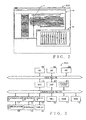
- Fig. 1 shows an embodiment of a system of the present invention where at least one controller device (external remote controller) is connected to a PC (Personal Computer) 1.
- the PC 1 has installed therein DAW (Digital Audio Workstation) software that is application software for implementing audio processing functions, such as recording and reproduction, effect impartment, mixing etc. of audio signals.
- DAW Digital Audio Workstation
- Two external remote controllers 2 and 3 each of which is a dedicated controller device for manipulating the DAW software, are connected to the PC 1.
- the PC 1 includes a plurality of USB (Universal Serial Bus) terminals of a USB interface that is one of serial interface standards for interconnecting peripheral devices and a PC, and the external remote controllers 2 and 3 too include USB terminals.
- the PC 1 and the external remote controllers 2 and 3 are communicatively interconnected via USB cables interconnecting their respective USB terminals.
- the external remote controllers 2 and 3 can remote-control parameters of individual channels in the DAW software.
- n e.g., four
- the external remote controllers 2 and 3 are of a same construction, and thus, the following describe representatively the construction of the external remote controller 2.
- the external remote controller 2 includes four faders Fd2a, Fd2b, Fd2c and Fd2d.
- Each of the four faders Fd2a to Fd2d is in the form of a vertically elongated touch panel and is capable of adjusting a fader level of a channel assigned thereto by a human operator or user sliding its finger or the like on and along the touch panel.
- a display section Lv2a, Lv2b, Lv2c or Lv2d that comprises a plurality of LEDs disposed at substantially equal intervals along the longitudinal axis of the touch panel.
- each of the display sections Lv2a - Lv2d one of the LEDs which corresponds to a current position of a fader knob (i.e., fader level) of the channel assigned thereto (i.e., corresponding channel) is lit or illuminated.
- a fader knob i.e., fader level
- the position of the corresponding fader knob is moved, so that the LED illuminated in the corresponding display section Lv2a - Lv2d is moved in accordance with, i.e. in an interlocked relation to, the moved fader knob position.
- the position of the fader knob represents a fader level
- the fader level can be adjusted by the user sliding its finger or the like on and along the fader Fd2a - Fd2d.
- Fig. 2 shows a GUI (Graphical User Interface) screen of the DAW software displayed on the PC 1 which has the external remote controllers 2 and 3 connected thereto as shown in Fig. 1 and on which the DAW software is running.
- a window Wa of a sequencer and a window Wb of a mixer are being displayed on the GUI screen of the DAW software.
- the window Wa is a GUI permitting production of a music piece, on which information of a plurality of tracks of performance data and track-by-track performance data are time-serially displayed in horizontally elongated rectangles.
- a cursor c gradually moves rightward at a speed corresponding to a tempo, during which the performance data of the individual tracks at each cursor position are reproduced.
- a mixer function is performed or implemented such that, at the time of reproduction, audio signals of the individual tracks are output after being mixed by the mixer.
- the window Wb which is a GUI of the mixer that mixes audio signals of the individual tracks, are displayed at least the faders of the plurality of channels for adjusting mixing levels of the individual tracks. The user can adjust the mixing levels by moving or dragging the corresponding fader knobs on the screen to thereby adjust fader levels of the channels (tracks) assigned to the faders.
- the faders of, for example, twelve channels are being displayed on the window Wb, and the displayed channels, comprising the tracks, can be assigned to the individual faders.
- a control section that controls the channel assignment and stores the controlled results is included in the PC 1 (i.e., incorporated as application software).
- Positions of the fader knobs can be remote-controlled with the external remote controller 2 in place of the faders displayed on the window Wb.
- positions of the fader knobs of channels assigned to the four faders Fd2a to Fd2d of the external remote controllers 2 are remote-controlled.
- four channels of desired increasing or ascending consecutive channel numbers can be assigned to the faders Fd2a to Fd2d (namely, the four channels can be assigned to the faders Fd2a to Fd2d in ascending order of the channel numbers); channels of random non-consecutive channel numbers cannot be assigned to the faders Fd2a to Fd2d.
- the assigned four channels can be changed by the user depressing a channel shift button provided in a "Channel” section or a bank shift button provided in a "Bank” section of the external remote controller 2 shown in Fig. 1 .
- a channel shift button provided in a "Channel” section or a bank shift button provided in a "Bank” section of the external remote controller 2 shown in Fig. 1 .
- the channels assigned to the faders Fd2a to Fd2d are shifted by one channel in a channel-No. decreasing or descending direction.
- the " ⁇ " button Cd2 with channels of channel Nos.
- channels ch3 to ch6 assigned to the faders Fd2a to Fd2d
- channels ch2 to ch5 are assigned to the faders Fd2a to Fd2d.
- the channels assigned to the faders Fd2a to Fd2d are shifted by one channel in a channel-No. increasing or ascending direction.
- channels ch4 to ch7 are assigned to the faders Fd2a to Fd2d.
- the channels assigned to the faders Fd2a to Fd2d are shifted by one bank (in this case, four channels) in the channel-No. decreasing or descending direction.
- the channels ch2 to ch5 are assigned to the faders Fd2a to Fd2d.
- the channels assigned to the faders Fd2a to Fd2d are shifted by one bank (four channels) in the channel-No. increasing or descending direction.
- the " ⁇ " button Bd2 may be called “leftward bank shift button”
- the ">” button Bu2 may be called “rightward bank shift button”.
- four channels of desired ascending consecutive channel numbers can be assigned to the faders Fd2a to Fd2d (namely, the four channels can be assigned to the faders Fd2a to Fd2d in ascending order of the channel numbers) independently of a channel selected on the window Wb of the PC1.
- the function of the button Cd2 is switched to a "Select" function so that four channels of desired ascending consecutive channel numbers, starting with the channel currently selected on the window Wb of the PC 1, are assigned to the faders Fd2a to Fd2d.
- channels ch3 to ch6 are assigned to the faders Fd2a to Fd2d.
- the function of the button Cu2 is switched to a "Meter” function (i.e., level meter display function) so that input levels of four channels assigned to the faders Fd2a to Fd2d are displayed on the corresponding display sections Lv2a to Lv2d. If the user operates, i.e.
- the external remote controller 3 has the same functions as the external remote controller 2; namely, the external remote controllers 2 and 3 are constructed to behave in the same manner.
- Fig. 3 is a block diagram showing an example hardware setup of the PC 1 in which the DAW software is installed.
- a CPU Central Processing Unit
- the PC 1 also includes a non-volatile ROM (Read-Only Memory) 11 in which are stored various programs and various data, and a RAM (Random Access Memory) 11 in which are stored a working area of the CPU 10 and various data.
- ROM Read-Only Memory
- RAM Random Access Memory
- the PC 1 includes a storage device 21 that may be a drive device provided with any of various recording media, such as a hard disk HD, compact disk CD and flexible disk FD, and various applications, such as the DAW software, are stored in the hard disk HD.
- the PC 1 implements the audio processing functions, such as recording and reproduction, effect impartment, mixing etc. of audio signals, so that desired music production can be readily performed by use of the PC 1.
- a display IF 13 is a display interface for displaying, on a display section 14 such as a liquid crystal display, various GUI screens of currently operating applications.
- a detection IF 15 is an interface for scanning controls (operators) 16, such as switches, provided on the PC 1 to detect operation of any of the controls 16, so that an operation signal corresponding to the operated control 16.
- a communication IF 17 is a communication interface for performing communication with an external device, such as a controller device, via a communication I/O 18, and the communication IF 17 is, for example, a USB or Ethernet (registered trademark) interface.
- An effecter (EFX) 19 imparts, under the control of the CPU 10, effects, such as reverberation, echo and chorus, to audio signals having been mixed by the DAW software.
- a DSP 20 performs audio signal processing for mixing input audio signals after adjusting sound volume levels and frequency characteristics of the audio signals on the basis of respective parameters and then controlling audio characteristics, such as sound volume, panning and effect, of the mixed audio signals on the basis of respective parameters.
- the above-mentioned CPU 10, ROM 11, RAM 12, display IF 13, detection IF 15, communication IF 17, EFX 19, DSP 20 and storage device 21 communicate data with one another via a communication bus 22.
- An AD 23 comprises a plurality of analog input ports for inputting analog signals to the PC 1, and the analog signals thus input are converted via the AD 23 into digital signals and then sent to an audio bus 26.
- a DA 24 comprises a plurality of analog output ports for outputting mixed analog signals from the PC 1, and digital signals received via the audio bus 24 are converted by the DA 24 into audio signals and output from the DA 24.
- a DD 25 comprises a plurality of input/output ports for not only inputting digital signals to the PC 1 but also outputting mixed digital signals to the outside. Digital input signals input via the DD 25 are sent to the audio bus 26, and digital output signals received via the audio bus 26 are output to a digital recorder or the like.
- the EFX 19 and the DSP 20 communicate data etc. with the AD 23, DA 24 and DD 25 via the audio bus 26. Note that the digital signals sent from the AD 23 and DD 25 are received by the DSP 20 so that the aforementioned digital signal processing is performed by the DSP 20 on the received audio signals.
- AD 23, DA24 and DD 25 may be provided in the PC 1
- the AD 23, DA24 and DD 25 may be implemented by software in the PC 1. Further, if the CPU 10 is constructed to perform the audio signal processing in place of the DSP 20, the DSP 20 can be dispensed with.
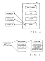
- Fig. 4 shows a hierarchical structure of the PC to which are connected the external remote controllers according to an embodiment of the invention connected thereto.
- three external remote controllers 2, 3 and 4 are connected to the PC 1 via USB cables connected to their respective USB terminals.
- the external remote controllers 2, 3 and 4 are connected to ports 1a of different port numbers of the PC 1 under the control of the OS 1c.
- the port numbers depend on a driver 1b used, and correspondence relationship between the ports numbers and the external remote controllers 2, 3 and 4 is stored by the OS 1c.
- the external remote controllers 2, 3 and 4 are logically connected to different port names of MIDI ports of the DAW software under the control of the OS 1c. Correspondence relationship between the port names and the external remote controllers 2, 3 and 4 is determined and stored by the DAW software. In this way, communication between the DAW software 1d and the external remote controllers 2, 3 and 4 can be performed under the control of the OS 1c.
- the external remote controllers 2, 3 and 4 When the external remote controllers 2, 3 and 4 have been connected to the PC 1 and the DAW software 1d has been activated for the first time, the external remote controllers 2, 3 and 4 are newly registered into the DAW software in order of indexes allocated to the port names of the MIDI ports.
- the indexes allocated to the port names depend on the driver 1b and are, for example, in the form of MAC (Media Access Control) addresses or serial numbers, such as manufacturer's serial numbers, of the external remote controllers 2, 3 and 4 connected to the ports.
- controller IDs are allocated to the external remote controllers 2, 3 and 4, using the indexes of the individual port names, such that each of the external remote controllers 2, 3 and 4 can be uniquely identified.
- the DAW software manages and stores respective properties of the external remote controllers 2, 3 and 4 registered in the DAW software. The properties include the names of the ports, having the external remote controllers 2, 3 and 4 connected thereto, and the allocated controller IDs.
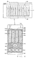
- Fig. 5 is a conceptual diagram explanatory of controller information of the external remote controllers that is stored in the working area of the RAM 12 used by the DAW software.
- the controller information includes information indicative of a channel number of a first (or leading) one of all of the channels last assigned to the external remote controllers and properties of external remote controllers A, B, ... registered in the DAW software in the order of the indexes allocated to the port names.
- the properties of each of the external remote controllers A, B, ... include the port name of the port, having the external remote controller connected thereto, allocated controller ID, channel number of a first one of the channels assigned to the external remote controller and the (total) number of faders provided in the external remote controller.
- controller information shown in Fig. 5 is stored into the non-volatile storage device 21 when the DAW software has been deactivated, so that it can be read out from the storage device 21 and set into the RAM 12 upon subsequent activation of the DAW software (i.e., next activation of the DAW software following the last deactivation).
- the channels last assigned to the external remote controllers can be restored even when the external remote controllers are connected to the port names of MIDI ports different from those which they were connected to last time.
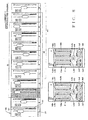
- Fig. 6 shows a basic form of channel assignment to the external remote controller.
- the mixer function is implemented, so that a "mixer" screen is displayed on the window Wb as shown in Fig. 6 .
- On the "mixer” screen are displayed twelve channel faders 30 of channels ch1 to ch12 that sequentially increase in channel number one by one in the left-to-right direction.
- the external remote controller 2 on the other hand, is provided with four faders Fd2a to Fd2d to which different channels can be assigned. Let's now consider a case where four channels ch3 to ch6, enclosed by broken line on the window Wb shown in Fig. 6 , have been assigned to the faders Fd2a to Fd2d.
- the position of the fader knob of channel ch3 can be remote-controlled to move by the user sliding its finger or the like on the corresponding fader Fd2a, and the LED illuminated on the display section Lv2a is moved in interlocked relation to the moved (i.e., moved-to) position of the fader knob.
- the other faders Fd2b, Fd2c and Fd2d are also possible.
- the position of the fader knob of channel ch4 - ch6 assigned to the fader can be remote-controlled to move, and the LED illuminated on the display section Lv2b - Lv2d is moved in interlocked relation to the moved-to position of the fader knob.
- the fader knob 31 of the corresponding channel fader 30 displayed on the mixer screen is moved in interlocked relation to the user's sliding operation.
- Fig. 7 a detailed example manner in which channels are assigned to the external remote controller 2 when the external remote controller 2 is connected to the PC 1.
- the DAW software is running on the PC 1
- twelve channel faders 30 of channels ch1 to ch12 are displayed on the mixer screen of the window Wb.
- just one external remote controller 2 is connected to the PC 1.
- Each of the channel faders 30 includes the fader knob 31, level meter 33, mute button "m" and solo button “s”.
- an input level of the assigned channel is displayed on the level meter 33, and switching can be made between mute ON and mute OFF states of the channel via the mute button "m". Further, switching can be made between solo ON and solo OFF states of the channel via the solo button "s". Furthermore, the channel number 32 of each of the channel faders 30 is displayed at the bottom of the channel fader 30. Also, in the illustrated example of Fig. 7 , the channel fader 30 of channel ch3, whose background is displayed in a gray color, is a currently selected channel fader.
- channels ch3 to ch6 in a "current assigned range 40" are channels currently assigned to the faders Fd2a to Fd2d. If the user depresses the channel rightward button Cu2 (">") of the external remote controller 2 in a state as indicated by such a current assigned range 40, the channels assigned to the faders Fd2a to Fd2d are shifted by one channel in the rightward direction, as a result of which channels ch4 to ch7 are assigned to the faders Fd2a to Fd2d as indicated by a "channel-shifted assigned range 41".
- the channels assigned to the faders Fd2a to Fd2d are shifted by one bank in the rightward direction, as a result of which channels ch8 to ch11 are assigned to the faders Fd2a to Fd2d as indicated by a "bank-shifted assigned range 42".
- one bank has a size of four channels that is equal to the number of the faders provided in the external remote controller 2.
- the channels assigned to the faders Fd2a to Fd2d are shifted by one channel in the leftward direction, as a result of which channels ch2 to ch5 are assigned to the faders Fd2a to Fd2d.
- the bank leftward button Bd2 (" ⁇ ") of the external remote controller 2 in the state as indicated by the channel-shifted assigned range 41 the channels assigned to the faders Fd2a to Fd2d are shifted by one bank in the leftward direction.
- the channels assigned to the faders Fd2a to Fd2d are shifted by only three channels in the leftward direction because there are only three channels, less than the one bank size, to the left of the channel-shifted assigned state 41, so that channel ch1 that is of the smallest channel number is assigned to the leftmost-end fader Fd2a and the channels of ascending consecutive channel numbers ch2 to ch4 are assigned to the faders Fd2b to Fd2d following the leftmost-end fader Fd2a; in the aforementioned manner, channels ch1 to ch4 are assigned to the faders Fd2a to Fd2d.
- Fig. 8 a detailed manner in which channels are assigned to the eternal remote controllers 2 and 3 when the two external remote controllers 2 and 3 are connected to the PC 1.
- the DAW software is running on the PC 1
- twelve channel faders 30 of channels ch1 to ch12 are displayed on the mixer screen of the window Wb.
- one bank size is eight channels that is equal to the total number of the faders provided on the two external remote controllers 2 and 3.
- the channel fader 30 of channel ch3, whose background is displayed in a gray color is a currently selected channel fader.
- channels ch3 to ch10 in a "current assigned range” 45 are currently assigned to the faders Fd2a to Fd2d and faders Fd3a to Fd3d. If the user depresses the channel rightward button Cu2 (">") of the external remote controller 2 or the channel rightward button Cu3 (">") of the external remote controller 3 in a state as indicated by such a current assigned range 45, the channels assigned to the faders Fd2a to Fd2d and Fd3a to Fd3d are shifted by one channel in the rightward direction, as a result of which channels ch4 to ch11 are assigned to the faders Fd2a to Fd2d and Fd3a to Fd3d as indicated by a "channel-sifted assigned range 46".
- the channels assigned to the faders Fd2a to Fd2d and Fd3a to Fd3d are shifted by one bank, i.e. eight channels, in the rightward direction.
- the channels are shifted by one channel in the rightward direction, as a result of which channel ch12 of the greatest channel number is assigned to the rightmost-end fader Fd3d and channels ch11 to ch5 of the preceding descending consecutive channel numbers are assigned to the faders Fd3c to Fd3a and the faders Fd2d to Fd2a (namely, channels ch11 to ch5 are assigned to the faders Fd2a to Fd2d in descending order of the channel numbers) as indicated by a bank-shifted assigned state 47.
- the channels assigned to the faders Fd2a to Fd2d are shifted by one channel in the leftward direction, as a result of which channels ch2 to ch9 are assigned to the faders Fd2a to Fd2d and Fd3a to Fd3d.
- the channels assigned to the faders Fd2a to Fd2d and Fd3a to Fd3d are shifted by one bank, i.e. eight channels, in the leftward direction.
- the channels are shifted by only three channels in the leftward direction, as a result of which channel ch1 of the smallest channel number is assigned to the leftmost-end fader Fd2a and channels ch2 to ch8 of the following ascending consecutive channel numbers are assigned to the faders Fd2b to Fd2d and the faders Fd3a to Fd3d.
- the DAW software performs the channel assignment process, regarding or considering the product (n * m) as the number of channels constituting one bank size. Namely, even where n external remote controllers are connected to the PC 1, the DAW software considers that only one external remote controller provided with the (n * m) faders is logically connected to the PC 1.
- the indexes are MAC addresses or serial numbers, such as manufacturer's serial numbers, of the external remote controllers connected to the ports of the port names. If the order of the indexes of the port names is "(A) ⁇ (B) ⁇ (C)", then the three external remote controllers are registered into the DAW software upon the initial activation of the DAW software in the order of the indexes, i.e. "Controller A ⁇ Controller B ⁇ controller C", as shown in Fig. 9B . Note that the indexes of the port names depend on the driver 1b.
- Unique controller IDs are allocated, under the control of the DAW software, to the three external remote controllers, Controller A, Controller B and Controller C, newly registered upon the initial activation of the DAW software, and channels are assigned to the external remote controllers in the order of the indexes of the port names starting with the first channel number as indicated in Fig. 9B .
- channels of ascending consecutive channel numbers starting with channel ch1 that is the leading or first channel of various channels currently handled in the DAW software, are assigned to the external remote controllers in the order of Controller A ⁇ Controller B ⁇ Controller C.
- channels ch1 to ch4 are assigned to Controller A
- channels ch5 to ch8 are assigned to Controller B
- channels ch9 to ch12 are assigned to Controller C.
- the DAW software considers that one logical external remote control provided with sixteen faders is connected to the PC 1, sets sixteen channels as one bank size, and assigns sixteen channels ch1 to ch16, constituting one bank size, to the four external remote controllers. In this case, channels ch13 to ch16 are assigned to the fourth external remote controller.
- the controller information to be stored upon the initial activation of the DAW software includes the channel number of the first channel ch1 of all the channels assigned to the external remote controllers, and profiles of Controller A, Controller B and Controller C.
- the profile of each of Controller A, Controller B and Controller C includes the respective port name, controller ID, channel number of the first channel of the channels assigned to the external remote controller and the number of faders provided in the external remote controller.
- Fig. 10A shows channel assignment to external remote controllers at the time of last deactivation of the DAW software
- Fig. 10B shows channel assignment to external remote controllers at the time of next activation of the DAW software following the last deactivation.
- three external remote controllers, Controller A, Controller B and Controller C were (had been) registered in the DAW software, and channels ch1 to ch4 were assigned to Controller A, channels ch5 to ch8 assigned to Controller B, and channels ch9 to ch12 assigned to Controller C.
- the DAW software stores the above-mentioned controller information.
- the DAW software identifies the controller IDs of the external remote controllers, determined to be currently connected to the PC 1, on the basis of the MAC addresses or serial numbers, such as the manufacture's serial numbers, of the external remote controllers.
- the controller IDs of Controller A, Controller B and Controller C are identified by the DAW software.
- the DAW software reads out the stored controller information and determines, on the basis of the controller IDs identified upon the next activation, whether the connected external remote controllers have already been registered in the DAW software and whether the organization (i.e., combination and arrangement) of the connected external remote controllers is the same as that at the time of the last deactivation.
- the DAW software determines that the connected Controller A, Controller B and Controller C have been registered and the organization of the connected controllers is the same as that at the time of the last deactivation.
- the DAW software performs the channel assignment, considering twelve channels as the number of channels constituting one bank size.
- the DAW software assigns twelve channels ch1. to ch12 to Controller A, Controller B and Controller C logically considered as a single external remote controller provided with twelve faders. Namely, channels ch1 to ch4 are assigned to Controller A, channels ch5 to ch8 are assigned to Controller B, and channels ch9 to ch12 are assigned to Controller C, and in this way, the same assignment state as at the time of the last deactivation is restored.
- the DAW software determines whether the currently connected external remote controllers are the same as those connected at the time of the last deactivation, on the basis of the controller IDs of the external remote controllers in place of the port names. Thus, even where the port names to which the external remote controllers have been connected at the time of the next activation are different (have changed) from those at the time of the last deactivation, the DAW software can accurately determine whether the connected external remote controllers have already been registered.
- channels ch13 to ch16 are assigned to the fourth external remote controller, and in this way, the same assignment state as at the time of the last deactivation is restored.
- Fig. 11A shows channel assignment to external remote controllers at the time of the last deactivation of the DAW software
- Fig. 11B shows channel assignment to external remote controllers in a case where the number of external remote controllers connected to the PC 1 at the time of the next activation has decreased from that at the time of the last deactivation.
- three external remote controllers, Controller A, Controller B and controller C were (had been) registered in the DAW software, and channels ch1 to ch4 were assigned to Controller A, channels ch5 to ch8 assigned to Controller B, and channels ch9 to ch12 assigned to Controller C.
- the DAW software stores the above-mentioned controller information. Then, once the thus-deactivated DAW software is activated again (i.e., upon the next activation), the DAW software identifies the controller IDs of the external remote controllers, determined to be currently connected to the PC 1, on the basis of the MAC addresses or serial numbers, such as the manufacture's serial numbers, of the external remote controllers. In the illustrated example of Fig. 11B , the controller IDs of two external remote controllers, Controller A and Controller B, are identified by the DAW software.
- the DAW software reads out the stored controller information and determines, on the basis of the controller IDs identified upon the next activation, whether the connected external remote controllers have been registered and whether the organization of the connected external remote controllers is the same as that at the time of the last deactivation.
- the DAW software determines that the connected controllers have been registered, but determines that the organization of the external remote controllers is different from that at the time of the last deactivation where Controller B was connected to the PC 1. Because, in this case, only two external remote controllers are connected to the PC 1, the DAW software performs the channel assignment, considering eight channels as the number of channels constituting one bank size.
- the DAW software assigns eight channels ch1 to ch8 to Controller A and controller C logically considered as a single external remote controller provided with eight faders. Namely, channels ch1 to ch4 are assigned to Controller A, and channels ch5 to ch8 are assigned to Controller C, as shown in Fig. 11B . Then, the DAW software stores controller information reflecting therein the changed assignment state.
- the DAW software determines whether the currently connected external remote controllers are the same as those connected at the time of the last deactivation, on the basis of the controller IDs of the external remote controllers in place of the port names. Thus, even where the port names to which the external remote controllers have been connected at the time of the next activation are different (have changed) from those at the time of the last deactivation, the DAW software can accurately determine whether the connected external remote controllers have been registered.
- channels ch9 to ch12 are assigned to the third the external remote controller and channels ch13 to ch16 are assigned to the fourth external remote controller.
- Fig. 12A shows channel assignment to external remote controllers at the time of the last deactivation of the DAW software
- Fig. 12B shows channel assignment to external remote controllers in a case where the number of external remote controllers connected to the PC 1 at the time of the next activation has increased from that at the time of the last deactivation.
- three external remote controllers, Controller A, Controller B and Controller C were registered in the DAW software, and channels ch1 to ch4 were assigned to Controller A, channels ch5 to ch8 assigned to Controller B, and channels ch9 to ch12 assigned to Controller C.
- the DAW software stores the above-mentioned controller information. Then, once the thus-deactivated DAW software is activated again (i.e., upon the next activation), the DAW software identifies the controller IDs of the external remote controllers, determined to be currently connected to the PC 1, on the basis of the MAC addresses or serial numbers, such as the manufacture's serial numbers, of the external remote controllers. In the illustrated example of Fig. 12B , the controller IDs of three external remote controllers, Controller A, Controller B and Controller C, are identified by the DAW software, but the controller ID of the fourth external remote controller is not identified because the fourth external remote controller (Controller D) has not yet been registered.
- the DAW software reads out the stored controller information and determines, on the basis of the controller IDs identified upon the next activation, whether the connected external remote controllers have already been registered and whether the organization of the connected external remote controllers is the same as that the time of the last deactivation.
- the DAW software determines that the connected controllers, Controller A, Controller B and Controller C, have already been registered, but determines that the fourth external remote controller (Controller D) has not yet been registered. Also, the DAW software determines that the organization of the external remote controllers is different (has changed) from that at the time of the last deactivation because the fourth external remote controller (Controller D) has been newly connected. In this case, the DAW software creates controller information including the controller ID of the newly connected fourth external remote controller and registers Controller D immediately following the registered position of Controller C. Because four external remote controllers are connected to the PC 1, the DAW software performs the channel assignment, considering sixteen channels as the number of channels constituting one bank size.
- the DAW software assigns sixteen channels ch1 to ch16 to Controller A , Controller B, controller C and Controller D logically considered as a single external remote controller provided with sixteen faders.
- channels ch1 to ch16 are assigned with higher priority on the earlier registered external remote controllers, i.e. Controller A , Controller B and controller C.
- channels ch1 to ch4 are assigned to Controller A, channels ch5 to ch8 assigned to Controller B, channels ch9 to ch12 assigned to Controller C, and channels ch13 to ch16 assigned to Controller D, as shown in Fig. 12B .
- the DAW software stores controller information reflecting therein the changed assigned state.
- the DAW software determines whether the currently connected external remote controllers are the same as those connected at the time of the last deactivation, on the basis of the controller IDs of the external remote controllers in place of the port names. Thus, even where the port names to which the external remote controllers have been connected at the time of the next activation are different (has changed) from those at the time of the last deactivation, the DAW software can accurately determine whether the connected external remote controllers have been registered.
- channels ch13 to ch16 are assigned to the fourth the external remote controller, and in this way, the same assignment state as at the time of the last deactivation is restored.
- Fig. 13A shows channel assignment to external remote controllers at the time of the last deactivation of the DAW software
- Fig. 13B shows channel assignment to external remote controllers in a case where different external remote controllers from those at the time of the last deactivation have been connected at the time of the next activation.
- three external remote controllers, Controller A, Controller B and controller C were registered in the DAW software, and channels ch1 to ch4 were assigned to Controller A, channels ch5 to ch8 assigned to Controller B, and channels ch9 to ch12 assigned to Controller C.
- the DAW software stores the above-mentioned controller information.
- the DAW software identifies the controller IDs of the external remote controllers, determined to be currently connected to the PC 1, on the basis of the MAC addresses or serial numbers, such as the manufacture's serial numbers, of the external remote controllers.
- the controller ID of Controller C is identified by the DAW software, but the controllers ID of newly connected external remote controllers (second and third connected controllers in Fig. 13B , i.e. Controller D and Controller F) are not identified because the newly connected external remote controllers, Controller D and Controller F, have not yet been registered.
- the DAW software reads out the stored controller information and determines, on the basis of the controller ID identified upon the next activation, whether the connected external remote controllers have been registered and whether the organization of the connected external remote controllers is the same as that at the time of the last deactivation.
- the DAW software determines that Controller C currently connected to the DAW software has been registered, but determines that the newly connected external remote controllers, Controller D and Controller F, have not yet been registered. Also, the DAW software determines that the organization of the external remote controllers is different from that at the time of the last deactivation because (Controller D and Controller F) have been newly connected. In this case, the DAW software creates controller information including the controller IDs of the newly connected external remote controllers, i.e. Controller D and Controller F, and newly registers Controller D and Controller F in the order mentioned here. Because three external remote controllers are currently connected to the PC 1, the DAW software performs the channel assignment, considering twelve channels as the number of channels constituting one bank size.
- the DAW software assigns twelve channels ch1 to ch12 to Controller C, Controller D and Controller F logically considered as a single external remote controller provided with twelve faders.
- channels ch1 to ch12 are assigned with higher priority on the earlier registered external remote controller. Namely, channels ch1 to ch4 are assigned to Controller C, channels ch5 to ch8 assigned to Controller D, and channels ch9 to ch12 assigned to Controller F, as shown in Fig. 13B .
- the DAW software stores controller information reflecting therein the changed assignment state. If another new remote controller (i.e., fourth remote controller) has been connected to the PC 1 at the time of the next activation, channels ch13 to ch16 are assigned to the fourth remote controller.
- the DAW software determines whether the currently connected external remote controllers are the same as those connected at the time of the last deactivation, on the basis of the controller IDs of the external remote controllers in place of the port names. Thus, even where the port names to which the external remote controllers have been connected at the time of the next activation are different (has changed) from those at the time of the last deactivation, the DAW software can accurately determine whether the connected external remote controllers have been registered.
- the personal computer (PC) 1 having the DAW software installed therein includes a control section for controlling the assignment, storage of assigned results, etc. as described above with reference to Figs. 6 to 13B ; namely, application software for implementing the functions of the control section is incorporated in the PC 1.
- the present invention is not so limited, and another computer in the system may perform the functions of the control section.
- a control section for controlling the assignment, storage of assigned results, etc. as described above with reference to Figs. 6 to 13B may be included in each of the external remote controllers (controller devices) 2 and 3; namely, the application software for implementing the functions of the control section may be incorporated in each of the external remote controllers (controller devices) 2 and 3.
- the controller information indicative of an assignment state of channels to the controller devices at the time of the last deactivation of the DAW software is automatically stored, and channels are assigned to the controller devices at the time of the next activation (following the last deactivation) on the basis of the stored controller information.
- the present invention permits a seamless connection between the controller devices and the DAW software without the user caring about connecting and setting states of the controller devices. In this way, if only a desired controller device is physically connected to the DAW software, the controller device can be used in the same states as at the time of the last deactivation of the DAW software.
- the present invention can eliminate a need for resetting logical connection states in accordance with physical connection states.
- the controller device of the present invention may be practiced as a controller device for remote-controlling parameters of audio processing functions, such as recording and reproduction, effect impartment, mixing etc. of audio signals.
- the controller device of the present invention has been described as connected to a computer via a USB-based scheme, the scheme for physically connecting the controller device to the computer is not limited to the USB-based scheme and may be one using any other suitable communication interface.
- the maximum number of controller devices connectable to the computer is not necessarily limited to four and may be more than four.
Landscapes
- Engineering & Computer Science (AREA)
- Signal Processing (AREA)
- Circuit For Audible Band Transducer (AREA)
Abstract
Description
- The present invention relates to a system in which an external controller is connected to a computer having installed therein an application program, called "DAW" (Digital Audio Workstation) software, for implementing audio processing functions, such as recording and reproduction, effect impartment, mixing etc. of audio signals, and in which the DAW software is remote-controlled via the external controller.
- In the field of audio signal processing apparatus using a computer, it has heretofore been known to perform audio processing, such as recording, editing, mixing etc. of performance data, through digital signal processing. The audio signal processing apparatus employs a general-purpose computer, such as a PC (Personal Computer), and various types of hardware devices, such as an audio interface and MIDI (Musical Instrument Digital Interface) interface, necessary for the audio signal processing. Further, an application program for performing audio signal processing functions is installed in the computer. With such arrangements, audio signal processing functions, such as recording and reproduction, effect impartment, mixing etc. of audio signals, are implemented by the computer. Such audio signal processing apparatus are called "digital audio workstations" (DAWs). In the following description, the application program for the computer to perform such DAW functions will be referred to as "DAW software".
- The DAW software operating on a PC is well-developed such that even an individual person can easily perform music production by installing the DAW software in the PC. However, along with a recent increase in the number of functions of the DAW software, necessary parameters have increased, so that it has become difficult to manipulate all of the parameters through operation of a mouse alone. Thus, in some cases today, a dedicated external controller for manipulating the DAW software is connected to a PC having the DAW software installed therein so that the DAW software is controlled via the external controller. In such cases, designated parameters of channels set on the DAW software (or controller) can be remote-controlled.
- Examples of such techniques are disclosed in:
- Euphonix, Inc. MC Control User Guide, pp. 29 - 49, [online], Internet <http://connect.euphonix.com/documants/MC_Control_User_Guide_rC_Jap.pdf>, and
- Steinberg Media Technologies GmbH CC121 Operation Manual [online],Internet <ftp://ftp/steinberg.net/Download/Hardware/CC121/CC121_OperationManual_ja.pdf>
- Many of the dedicated controllers for manipulating the DAW software are for professional use and high-priced. Although there are also inexpensive controllers for personal use, they have only a small number of physical controls (or operators), and it is difficult to simultaneously manipulate a plurality of parameters and a plurality of tracks by use of such an inexpensive controller. Further, because, in many cases, the PC having the DAW software installed therein is for personal use and other external devices are connected to the PC, the controller does not always stay in a same physical connection state. Therefore, on occasion, there is a need to reset a connection state between the DAW software and the controller. Further, many of the types of controllers are designed on the premise that they are used on a stand-alone basis, and these types of controllers cannot be used simultaneously and in an interlocked fashion.
- In view of the foregoing prior art problems, it is an object of the present invention to provide an improved system which can eliminate a need for resetting a connection state between an external controller (controller device) and application software and which allows a plurality of external controllers (controller devices) to be connected to a computer and to operate in an interlocked fashion.
- In order to accomplish the above-mentioned object, the present invention provides an improved system including at least one controller device connectable to a computer where a mixer function is implemented by application software, the controller device comprising: a communication interface connectable to the computer; a plurality of faders each capable of remote-controlling parameters of one of a plurality of channels assigned thereto, the plurality of channels having consecutive channel numbers; a channel shift button operable to give an instruction for collectively shifting, by one channel, the channels assigned to the plurality of faders; and a bank shift button operable to give an instruction for collectively shifting, by one bank, the channels assigned to the plurality of faders, the one bank comprising a number of channels equal to a total number of the plurality of faders, the system comprising a control section which, upon activation of the application software, assigns channels, which are to be mixed by a mixer function, to the plurality of faders in ascending order of channel numbers starting with a predetermined first channel number, and which collectively shifts, by one channel, the channels assigned to the plurality of faders in response to the instruction given via the channel shift button or collectively shifts, by the one bank, the channels assigned to the plurality of faders in response to the instruction given via the bank shift button. When a plurality of the controller devices are connected to the computer, the control section not only assigns the channels to the faders, considering that a single controller device provided with a given number of faders, equal to a product between the total number of the controller devices connected to the computer and the total number of the faders provided in each of the controller devices, is connected to the computer, but also stores controller information including respective identification information of the controller devices connected to the computer and information indicative of a predetermined first channel of all of the channels assigned to the faders.
- According to the present invention, the control section handles a plurality of the controller devices connected to the computer as a single controller device provided with a given number of faders, equal to a product between the total number of the controller devices connected to the computer and the total number of the faders provided in each of the controller devices, but also stores the controller information including the respective identification information of the controller devices connected to the computer and information indicative of the predetermined first channel of all of the channels assigned to the faders. Thus, once the application software is activated with a plurality of the controller devices connected to the computer, settings of the channels at the time of last deactivation of the application software can be restored by reading out the stored controller information. Further, because the controller information includes the respective identification information of the controller devices connected to the computer, it is possible to eliminate a need for resetting (setting again) connection states of the controller devices with the application software.
- The present invention may be constructed and implemented not only as the apparatus invention discussed above but also as a method invention. Also, the present invention may be arranged and implemented as a software program for execution by a processor, such as a computer or DSP, as well as a non-transitory storage medium storing such a software program. In this case, the program may be provided to a user in the storage medium and then installed into a computer of the user, or delivered from a server apparatus to a computer of a client via a communication network and then installed into the client's computer. Further, the processor used in the present invention may comprise a dedicated processor with dedicated logic built in hardware, not to mention a computer or other general-purpose processor capable of running a desired software program.
- The following will describe embodiments of the present invention, but it should be appreciated that the present invention is not limited to the described embodiments and various modifications of the invention are possible without departing from the basic principles. The scope of the present invention is therefore to be determined solely by the appended claims.
- Certain preferred embodiments of the present invention will hereinafter be described in detail, by way of example only, with reference to the accompanying drawings, in which:
-
Fig. 1 a diagram showing an embodiment of a system of the present invention where controller devices are connected to a PC; -
Fig. 2 is a diagram showing a GUI screen of DAW software running on the PC which has the controller devices of the present invention connected thereto; -
Fig. 3 is a block diagram showing an example hardware setup of the PC to which the controller devices of the present invention are connected; -
Fig. 4 is a diagram showing a hierarchical structure of the PC having the controller devices of the present invention connected thereto; -
Fig. 5 is a conceptual diagram explanatory of controller information of the controller devices of the present invention; -
Fig. 6 is a diagram showing a basic form of assignment, to the controller device, of channels; -
Fig. 7 is a diagram showing an example detailed manner in which channels are assigned to one controller device of the present invention; -
Fig. 8 is a diagram showing an example detailed manner in which channels are assigned to two controller devices of the present invention; -
Figs. 9A and 9B are diagrams showing connection states of a plurality of controller devices of the present invention and channel assignments of the controller devices at the time of first activation of DAW software; -
Figs. 10A and 10B are diagrams showing an example of channel assignments of a plurality of controller devices of the present invention at the time of last deactivation and next activation, following the last deactivation, of the DAW software; -
Figs. 11A and 11B are diagrams showing another example of channel assignments of a plurality of controller devices of the present invention at the time of last deactivation and next activation of the DAW software; -
Figs. 12A and 12B are diagrams showing still another example of channel assignments of a plurality of controller devices of the present invention at the time of last deactivation and next activation of the DAW software; and -
Figs. 13A and 13B are diagrams showing still another example of channel assignments of a plurality of controller devices of the present invention at the time of last deactivation and next activation of the DAW software. -
Fig. 1 shows an embodiment of a system of the present invention where at least one controller device (external remote controller) is connected to a PC (Personal Computer) 1. InFig. 1 , the PC 1 has installed therein DAW (Digital Audio Workstation) software that is application software for implementing audio processing functions, such as recording and reproduction, effect impartment, mixing etc. of audio signals. Twoexternal remote controllers external remote controllers external remote controllers external remote controllers - Whereas, in the illustrated example of
Fig. 1 , twoexternal remote controllers PC 1, up to n (e.g., four) external remote controllers are connectable to thePC 1. The externalremote controllers remote controller 2. - As shown in
Fig. 1 , the externalremote controller 2 includes four faders Fd2a, Fd2b, Fd2c and Fd2d. Each of the four faders Fd2a to Fd2d is in the form of a vertically elongated touch panel and is capable of adjusting a fader level of a channel assigned thereto by a human operator or user sliding its finger or the like on and along the touch panel. In each of the faders Fd2a to Fd2d is incorporated a display section Lv2a, Lv2b, Lv2c or Lv2d that comprises a plurality of LEDs disposed at substantially equal intervals along the longitudinal axis of the touch panel. In each of the display sections Lv2a - Lv2d, one of the LEDs which corresponds to a current position of a fader knob (i.e., fader level) of the channel assigned thereto (i.e., corresponding channel) is lit or illuminated. As the user slides its finger or the like on and along any one of the faders Fd2a to Fd2d, the position of the corresponding fader knob is moved, so that the LED illuminated in the corresponding display section Lv2a - Lv2d is moved in accordance with, i.e. in an interlocked relation to, the moved fader knob position. Namely, because the position of the fader knob represents a fader level, the fader level can be adjusted by the user sliding its finger or the like on and along the fader Fd2a - Fd2d. -
Fig. 2 shows a GUI (Graphical User Interface) screen of the DAW software displayed on thePC 1 which has the externalremote controllers Fig. 1 and on which the DAW software is running. In the illustrated example ofFig. 2 , a window Wa of a sequencer and a window Wb of a mixer are being displayed on the GUI screen of the DAW software. The window Wa is a GUI permitting production of a music piece, on which information of a plurality of tracks of performance data and track-by-track performance data are time-serially displayed in horizontally elongated rectangles. Once a reproduction (play) button is depressed, a cursor c gradually moves rightward at a speed corresponding to a tempo, during which the performance data of the individual tracks at each cursor position are reproduced. Further, with the DAW software, a mixer function is performed or implemented such that, at the time of reproduction, audio signals of the individual tracks are output after being mixed by the mixer. On the window Wb, which is a GUI of the mixer that mixes audio signals of the individual tracks, are displayed at least the faders of the plurality of channels for adjusting mixing levels of the individual tracks. The user can adjust the mixing levels by moving or dragging the corresponding fader knobs on the screen to thereby adjust fader levels of the channels (tracks) assigned to the faders. - The faders of, for example, twelve channels are being displayed on the window Wb, and the displayed channels, comprising the tracks, can be assigned to the individual faders. As an example, a control section that controls the channel assignment and stores the controlled results is included in the PC 1 (i.e., incorporated as application software).
- Positions of the fader knobs can be remote-controlled with the external
remote controller 2 in place of the faders displayed on the window Wb. In this case, positions of the fader knobs of channels assigned to the four faders Fd2a to Fd2d of the externalremote controllers 2 are remote-controlled. In this case, four channels of desired increasing or ascending consecutive channel numbers can be assigned to the faders Fd2a to Fd2d (namely, the four channels can be assigned to the faders Fd2a to Fd2d in ascending order of the channel numbers); channels of random non-consecutive channel numbers cannot be assigned to the faders Fd2a to Fd2d. The assigned four channels can be changed by the user depressing a channel shift button provided in a "Channel" section or a bank shift button provided in a "Bank" section of the externalremote controller 2 shown inFig. 1 . Namely, if the user depresses a "<" button Cd2, the channels assigned to the faders Fd2a to Fd2d are shifted by one channel in a channel-No. decreasing or descending direction. For example, if the user depresses the "<" button Cd2 with channels of channel Nos. 3 to 6 (i.e., channels ch3 to ch6) assigned to the faders Fd2a to Fd2d, then channels ch2 to ch5 are assigned to the faders Fd2a to Fd2d. If the user depresses the ">" button Cu2 in the "Channel" section, the channels assigned to the faders Fd2a to Fd2d are shifted by one channel in a channel-No. increasing or ascending direction. For example, if the user depresses the ">" button Cu2 with channels ch3 to ch6 assigned to the faders Fd2a to Fd2d, then channels ch4 to ch7 are assigned to the faders Fd2a to Fd2d. Because the channels displayed on the window Wb sequentially increase in channel number in a left-to-right direction, the "<" button Cd2 may be called "leftward channel shift button", while the ">" button Cu2 may be called "rightward channel shift button". - Further, if the user depresses a "<" button Bd2 in the "Bank" section, the channels assigned to the faders Fd2a to Fd2d are shifted by one bank (in this case, four channels) in the channel-No. decreasing or descending direction. For example, if the user depresses the "<" button Bd2 with channels ch6 to ch9 assigned to the faders Fd2a to Fd2d, then channels ch2 to ch5 are assigned to the faders Fd2a to Fd2d. If the user depresses the ">" button Bu2 in the "Bank" section, the channels assigned to the faders Fd2a to Fd2d are shifted by one bank (four channels) in the channel-No. increasing or descending direction. For example, if the user depresses the ">" button Bu2 with channels ch6 to ch9 assigned to the faders Fd2a to Fd2d, then channels ch10 to ch13 are assigned to the faders Fd2a to Fd2d. Thus, the "<" button Bd2 may be called "leftward bank shift button", while the ">" button Bu2 may be called "rightward bank shift button".
- Namely, by the user depressing the channel shift button Cd2 or Cu2 or bank shift button Bd2 or Bu2, four channels of desired consecutive channel numbers can be assigned to the Fd2a to Fd2d.
- As noted above, four channels of desired ascending consecutive channel numbers can be assigned to the faders Fd2a to Fd2d (namely, the four channels can be assigned to the faders Fd2a to Fd2d in ascending order of the channel numbers) independently of a channel selected on the window Wb of the PC1. Note, however, that, if the user simultaneously depresses the "<" button Cd2 and a "Shift" button Sh2 of the external
remote controller 2, the function of the button Cd2 is switched to a "Select" function so that four channels of desired ascending consecutive channel numbers, starting with the channel currently selected on the window Wb of thePC 1, are assigned to the faders Fd2a to Fd2d. For example, if channel ch3 is currently selected on the window Wb, channels ch3 to ch6 are assigned to the faders Fd2a to Fd2d. Further, if the user simultaneously depresses the ">" button Cu2 and the "Shift" button Sh2, the function of the button Cu2 is switched to a "Meter" function (i.e., level meter display function) so that input levels of four channels assigned to the faders Fd2a to Fd2d are displayed on the corresponding display sections Lv2a to Lv2d. If the user operates, i.e. slides its finger on, any one of the faders Fd2a to Fd2d while level meters are displayed in response to the depression of the ">" button Cu2 and the "Shift" button Sh2, the display section of the operated fader displays a position of the fader knob for a given time and then returns back to the level meter display. Note that the above-mentioned level meter display function is in an OFF state when the externalremote controller 2 is activated. - The external
remote controller 3 has the same functions as the externalremote controller 2; namely, the externalremote controllers -
Fig. 3 is a block diagram showing an example hardware setup of thePC 1 in which the DAW software is installed. As shown inFig. 3 , a CPU (Central Processing Unit) 10 in thePC 1 executes a management program (Operating System or OS) so that general behavior of thePC 1 is controlled by the OS. ThePC 1 also includes a non-volatile ROM (Read-Only Memory) 11 in which are stored various programs and various data, and a RAM (Random Access Memory) 11 in which are stored a working area of theCPU 10 and various data. ThePC 1 includes astorage device 21 that may be a drive device provided with any of various recording media, such as a hard disk HD, compact disk CD and flexible disk FD, and various applications, such as the DAW software, are stored in the hard disk HD. By executing the DAW software, thePC 1 implements the audio processing functions, such as recording and reproduction, effect impartment, mixing etc. of audio signals, so that desired music production can be readily performed by use of thePC 1. - A display IF 13 is a display interface for displaying, on a
display section 14 such as a liquid crystal display, various GUI screens of currently operating applications. A detection IF 15 is an interface for scanning controls (operators) 16, such as switches, provided on thePC 1 to detect operation of any of thecontrols 16, so that an operation signal corresponding to the operatedcontrol 16. A communication IF 17 is a communication interface for performing communication with an external device, such as a controller device, via a communication I/O 18, and the communication IF 17 is, for example, a USB or Ethernet (registered trademark) interface. An effecter (EFX) 19 imparts, under the control of theCPU 10, effects, such as reverberation, echo and chorus, to audio signals having been mixed by the DAW software. Further, under the control of theCPU 10, aDSP 20 performs audio signal processing for mixing input audio signals after adjusting sound volume levels and frequency characteristics of the audio signals on the basis of respective parameters and then controlling audio characteristics, such as sound volume, panning and effect, of the mixed audio signals on the basis of respective parameters. The above-mentionedCPU 10,ROM 11,RAM 12, display IF 13, detection IF 15, communication IF 17, EFX 19,DSP 20 andstorage device 21 communicate data with one another via a communication bus 22. - An
AD 23 comprises a plurality of analog input ports for inputting analog signals to thePC 1, and the analog signals thus input are converted via theAD 23 into digital signals and then sent to an audio bus 26. ADA 24 comprises a plurality of analog output ports for outputting mixed analog signals from thePC 1, and digital signals received via theaudio bus 24 are converted by theDA 24 into audio signals and output from theDA 24. ADD 25 comprises a plurality of input/output ports for not only inputting digital signals to thePC 1 but also outputting mixed digital signals to the outside. Digital input signals input via theDD 25 are sent to the audio bus 26, and digital output signals received via the audio bus 26 are output to a digital recorder or the like. The EFX 19 and theDSP 20 communicate data etc. with theAD 23,DA 24 andDD 25 via the audio bus 26. Note that the digital signals sent from theAD 23 andDD 25 are received by theDSP 20 so that the aforementioned digital signal processing is performed by theDSP 20 on the received audio signals. - Whereas hardware of the
AD 23, DA24 andDD 25 may be provided in thePC 1, theAD 23, DA24 andDD 25 may be implemented by software in thePC 1. Further, if theCPU 10 is constructed to perform the audio signal processing in place of theDSP 20, theDSP 20 can be dispensed with. -
Fig. 4 shows a hierarchical structure of the PC to which are connected the external remote controllers according to an embodiment of the invention connected thereto. In the illustrated example ofFig. 4 , three externalremote controllers PC 1 via USB cables connected to their respective USB terminals. The externalremote controllers ports 1a of different port numbers of thePC 1 under the control of theOS 1c. The port numbers depend on adriver 1b used, and correspondence relationship between the ports numbers and the externalremote controllers OS 1c. Further, the externalremote controllers OS 1c. Correspondence relationship between the port names and the externalremote controllers DAW software 1d and the externalremote controllers OS 1c. - When the external
remote controllers PC 1 and theDAW software 1d has been activated for the first time, the externalremote controllers driver 1b and are, for example, in the form of MAC (Media Access Control) addresses or serial numbers, such as manufacturer's serial numbers, of the externalremote controllers DAW software 1d, controller IDs are allocated to the externalremote controllers remote controllers remote controllers remote controllers -
Fig. 5 is a conceptual diagram explanatory of controller information of the external remote controllers that is stored in the working area of theRAM 12 used by the DAW software. The controller information includes information indicative of a channel number of a first (or leading) one of all of the channels last assigned to the external remote controllers and properties of external remote controllers A, B, ... registered in the DAW software in the order of the indexes allocated to the port names. The properties of each of the external remote controllers A, B, ... include the port name of the port, having the external remote controller connected thereto, allocated controller ID, channel number of a first one of the channels assigned to the external remote controller and the (total) number of faders provided in the external remote controller. Note that the properties themselves are retained even after the registered external remote controller is detached or disconnected from thePC 1. Further, the controller information shown inFig. 5 is stored into thenon-volatile storage device 21 when the DAW software has been deactivated, so that it can be read out from thestorage device 21 and set into theRAM 12 upon subsequent activation of the DAW software (i.e., next activation of the DAW software following the last deactivation). - By using such controller information when the DAW software is activated next time, the channels last assigned to the external remote controllers can be restored even when the external remote controllers are connected to the port names of MIDI ports different from those which they were connected to last time.
-
Fig. 6 shows a basic form of channel assignment to the external remote controller. Upon activation of the DAW software, at least the mixer function is implemented, so that a "mixer" screen is displayed on the window Wb as shown inFig. 6 . On the "mixer" screen are displayed twelvechannel faders 30 of channels ch1 to ch12 that sequentially increase in channel number one by one in the left-to-right direction. The externalremote controller 2, on the other hand, is provided with four faders Fd2a to Fd2d to which different channels can be assigned. Let's now consider a case where four channels ch3 to ch6, enclosed by broken line on the window Wb shown inFig. 6 , have been assigned to the faders Fd2a to Fd2d. In this case, the position of the fader knob of channel ch3 can be remote-controlled to move by the user sliding its finger or the like on the corresponding fader Fd2a, and the LED illuminated on the display section Lv2a is moved in interlocked relation to the moved (i.e., moved-to) position of the fader knob. The same is true with the other faders Fd2b, Fd2c and Fd2d. Namely, by the user sliding its finger or the like on any one of the faders Fd2b to Fd2d, the position of the fader knob of channel ch4 - ch6 assigned to the fader can be remote-controlled to move, and the LED illuminated on the display section Lv2b - Lv2d is moved in interlocked relation to the moved-to position of the fader knob. - As the user slides its finger or the like on any one of the faders Fd2a to Fd2d of the external
remote controller 2, thefader knob 31 of thecorresponding channel fader 30 displayed on the mixer screen is moved in interlocked relation to the user's sliding operation. - The following describe, with reference to
Fig. 7 , a detailed example manner in which channels are assigned to the externalremote controller 2 when the externalremote controller 2 is connected to thePC 1. In the illustrated example ofFig. 7 , the DAW software is running on thePC 1, and twelvechannel faders 30 of channels ch1 to ch12 are displayed on the mixer screen of the window Wb. In this example, just one externalremote controller 2 is connected to thePC 1. Each of thechannel faders 30 includes thefader knob 31,level meter 33, mute button "m" and solo button "s". By the user dragging or moving thefader knob 31 of thechannel fader 30 via a pointing device, the fader level of the channel assigned to thechannel fader 30 can be adjusted. Further, an input level of the assigned channel is displayed on thelevel meter 33, and switching can be made between mute ON and mute OFF states of the channel via the mute button "m". Further, switching can be made between solo ON and solo OFF states of the channel via the solo button "s". Furthermore, thechannel number 32 of each of thechannel faders 30 is displayed at the bottom of thechannel fader 30. Also, in the illustrated example ofFig. 7 , thechannel fader 30 of channel ch3, whose background is displayed in a gray color, is a currently selected channel fader. - Let it also be assumed here that channels ch3 to ch6 in a "current assigned
range 40" are channels currently assigned to the faders Fd2a to Fd2d. If the user depresses the channel rightward button Cu2 (">") of the externalremote controller 2 in a state as indicated by such a current assignedrange 40, the channels assigned to the faders Fd2a to Fd2d are shifted by one channel in the rightward direction, as a result of which channels ch4 to ch7 are assigned to the faders Fd2a to Fd2d as indicated by a "channel-shifted assignedrange 41". If the user depresses the bank rightward button Bu2 (">") of the externalremote controller 2 in a state as indicated by the channel-shifted assignedstate 41, the channels assigned to the faders Fd2a to Fd2d are shifted by one bank in the rightward direction, as a result of which channels ch8 to ch11 are assigned to the faders Fd2a to Fd2d as indicated by a "bank-shifted assignedrange 42". In this case, because only one externalremote controller 2 is currently connected to thePC 1, one bank has a size of four channels that is equal to the number of the faders provided in the externalremote controller 2. - Further, if the user depresses the channel leftward button Cd2 ("<") of the external
remote controller 2 in the state as indicated by the current assignedrange 40, the channels assigned to the faders Fd2a to Fd2d are shifted by one channel in the leftward direction, as a result of which channels ch2 to ch5 are assigned to the faders Fd2a to Fd2d. If the user depresses the bank leftward button Bd2 ("<") of the externalremote controller 2 in the state as indicated by the channel-shifted assignedrange 41, the channels assigned to the faders Fd2a to Fd2d are shifted by one bank in the leftward direction. However, in this case, the channels assigned to the faders Fd2a to Fd2d are shifted by only three channels in the leftward direction because there are only three channels, less than the one bank size, to the left of the channel-shifted assignedstate 41, so that channel ch1 that is of the smallest channel number is assigned to the leftmost-end fader Fd2a and the channels of ascending consecutive channel numbers ch2 to ch4 are assigned to the faders Fd2b to Fd2d following the leftmost-end fader Fd2a; in the aforementioned manner, channels ch1 to ch4 are assigned to the faders Fd2a to Fd2d. - The following describe, with reference to
Fig. 8 , a detailed manner in which channels are assigned to the eternalremote controllers remote controllers PC 1. In the illustrated example ofFig. 8 , the DAW software is running on thePC 1, and twelvechannel faders 30 of channels ch1 to ch12 are displayed on the mixer screen of the window Wb. Because the externalremote controllers PC 1, one bank size is eight channels that is equal to the total number of the faders provided on the two externalremote controllers Fig. 8 , thechannel fader 30 of channel ch3, whose background is displayed in a gray color, is a currently selected channel fader. - Let it be assumed here that channels ch3 to ch10 in a "current assigned range" 45 are currently assigned to the faders Fd2a to Fd2d and faders Fd3a to Fd3d. If the user depresses the channel rightward button Cu2 (">") of the external
remote controller 2 or the channel rightward button Cu3 (">") of the externalremote controller 3 in a state as indicated by such a current assignedrange 45, the channels assigned to the faders Fd2a to Fd2d and Fd3a to Fd3d are shifted by one channel in the rightward direction, as a result of which channels ch4 to ch11 are assigned to the faders Fd2a to Fd2d and Fd3a to Fd3d as indicated by a "channel-sifted assignedrange 46". If the user depresses the bank rightward button Bu2 (">") of the externalremote controller 2 or the bank rightward button Bu3 (">") of the externalremote controller 3 in a state indicated by the channel-shifted assignedrange 46, the channels assigned to the faders Fd2a to Fd2d and Fd3a to Fd3d are shifted by one bank, i.e. eight channels, in the rightward direction. Actually, however, because the greatest channel number is "12" and thus there is only one channel, less than one bank size, to the right of the channel-shifted assignedrange 46, the channels are shifted by one channel in the rightward direction, as a result of which channel ch12 of the greatest channel number is assigned to the rightmost-end fader Fd3d and channels ch11 to ch5 of the preceding descending consecutive channel numbers are assigned to the faders Fd3c to Fd3a and the faders Fd2d to Fd2a (namely, channels ch11 to ch5 are assigned to the faders Fd2a to Fd2d in descending order of the channel numbers) as indicated by a bank-shifted assigned state 47. - Further, if the user depresses the channel leftward button Cd2 ("<") of the external
remote controller 2 or the channel leftward button Cd3 ("<") of the externalremote controller 3 in the state as indicated by the current assignedrange 45, the channels assigned to the faders Fd2a to Fd2d are shifted by one channel in the leftward direction, as a result of which channels ch2 to ch9 are assigned to the faders Fd2a to Fd2d and Fd3a to Fd3d. If the user depresses the bank leftward button Bd2 ("<") of the externalremote controller 2 or the bank leftward button Bd3 ("<") of the externalremote controller 3 in the state indicated by the channel-shifted assignedstate 46, the channels assigned to the faders Fd2a to Fd2d and Fd3a to Fd3d are shifted by one bank, i.e. eight channels, in the leftward direction. Actually, however, because the smallest channel number is "1" and there are only three channels, less than one bank size, to the left of the assignedrange 46, the channels are shifted by only three channels in the leftward direction, as a result of which channel ch1 of the smallest channel number is assigned to the leftmost-end fader Fd2a and channels ch2 to ch8 of the following ascending consecutive channel numbers are assigned to the faders Fd2b to Fd2d and the faders Fd3a to Fd3d. - As set forth above, in the case where n external remote controllers are connected to the
PC 1, no matter which one of the channel shift buttons and bank shift buttons of the n external remote controllers is operated, all channels assigned to these external remote controllers are shifted in response to the operated channel shift button or bank shift button. However, in a case where the user instructs, through shift button operation, that a shift be effected beyond the channel of the smallest or greatest channel number, a channel shift is effected only up to the channel of the smallest or greatest channel number, i.e. a channel shift beyond the channel of the smallest or greatest channel number is inhibited. Namely, if the assigned range cannot be shifted by the number of channels as instructed through the user's operation of any one of the shift buttons, an exceptional channel assignment process is performed in which a channel shift is effected only up to the channel of the smallest or greatest channel number and then terminated. - Further, in the case where n external remote controllers are connected to the
PC 1 and m faders are provided in each of the external remote controllers, the DAW software performs the channel assignment process, regarding or considering the product (n * m) as the number of channels constituting one bank size. Namely, even where n external remote controllers are connected to thePC 1, the DAW software considers that only one external remote controller provided with the (n * m) faders is logically connected to thePC 1. -
Fig. 9A shows a connection state in which three external remote controllers are connected to thePC 1, andFig. 9B shows an example manner in which channels are assigned upon initial activation of the DAW software in the connection state ofFig. 9A . Once the DAW software is activated for the first time (i.e., upon initial activation of the DAW software) in the connection state ofFig. 9A , the DAW software determines which external remote controllers are currently connected to which port names of the MIDI ports, and the external remote controllers are newly registered into the DAW software in the order of the indexes of the port names to which the external remote controllers are connected. The indexes are MAC addresses or serial numbers, such as manufacturer's serial numbers, of the external remote controllers connected to the ports of the port names. If the order of the indexes of the port names is "(A)→(B)→(C)", then the three external remote controllers are registered into the DAW software upon the initial activation of the DAW software in the order of the indexes, i.e. "Controller A→Controller B→controller C", as shown inFig. 9B . Note that the indexes of the port names depend on thedriver 1b. - Unique controller IDs are allocated, under the control of the DAW software, to the three external remote controllers, Controller A, Controller B and Controller C, newly registered upon the initial activation of the DAW software, and channels are assigned to the external remote controllers in the order of the indexes of the port names starting with the first channel number as indicated in
Fig. 9B . Namely, upon the initial activation of the DAW software, channels of ascending consecutive channel numbers, starting with channel ch1 that is the leading or first channel of various channels currently handled in the DAW software, are assigned to the external remote controllers in the order of Controller A→Controller B→ Controller C. In the case where the three external remote controllers, Controller A, Controller B and Controller C, are connected to thePC 1 as noted above, the DAW software performs the channel assignment, considering the product (n * m) as the number of channels constituting one bank size. In this case, because each of the external remote controllers has four faders, the DAW software assigns twelve channels ch1 to ch12 (3 * 4 = 12) to Controller A, Controller B and controller C logically regarded or considered as a single external remote controller provided with twelve faders. - As a consequence, channels ch1 to ch4 are assigned to Controller A, channels ch5 to ch8 are assigned to Controller B, and channels ch9 to ch12 are assigned to Controller C. Further, in a case where the fourth external remote controller in addition to the first to third external remote controller is connected to the
PC 1, the DAW software considers that one logical external remote control provided with sixteen faders is connected to thePC 1, sets sixteen channels as one bank size, and assigns sixteen channels ch1 to ch16, constituting one bank size, to the four external remote controllers. In this case, channels ch13 to ch16 are assigned to the fourth external remote controller. - The controller information to be stored upon the initial activation of the DAW software includes the channel number of the first channel ch1 of all the channels assigned to the external remote controllers, and profiles of Controller A, Controller B and Controller C. The profile of each of Controller A, Controller B and Controller C includes the respective port name, controller ID, channel number of the first channel of the channels assigned to the external remote controller and the number of faders provided in the external remote controller.
-
Fig. 10A shows channel assignment to external remote controllers at the time of last deactivation of the DAW software, andFig. 10B shows channel assignment to external remote controllers at the time of next activation of the DAW software following the last deactivation. Namely, at the time of the last deactivation of the DAW software shown inFig. 10A , three external remote controllers, Controller A, Controller B and Controller C, were (had been) registered in the DAW software, and channels ch1 to ch4 were assigned to Controller A, channels ch5 to ch8 assigned to Controller B, and channels ch9 to ch12 assigned to Controller C. Also, at the time of the deactivation, the DAW software stores the above-mentioned controller information. Then, once the thus-deactivated DAW software is activated again (i.e., upon the next activation), the DAW software identifies the controller IDs of the external remote controllers, determined to be currently connected to thePC 1, on the basis of the MAC addresses or serial numbers, such as the manufacture's serial numbers, of the external remote controllers. In the illustrated example ofFig. 10B , the controller IDs of Controller A, Controller B and Controller C are identified by the DAW software. Then, the DAW software reads out the stored controller information and determines, on the basis of the controller IDs identified upon the next activation, whether the connected external remote controllers have already been registered in the DAW software and whether the organization (i.e., combination and arrangement) of the connected external remote controllers is the same as that at the time of the last deactivation. In the illustrated example ofFig. 10B , where Controller A, Controller B and Controller C are connected to thePC 1, the DAW software determines that the connected Controller A, Controller B and Controller C have been registered and the organization of the connected controllers is the same as that at the time of the last deactivation. Then, the DAW software performs the channel assignment, considering twelve channels as the number of channels constituting one bank size. Here, because the leading or first channel in the controller information is of channel number ch1, the DAW software assigns twelve channels ch1. to ch12 to Controller A, Controller B and Controller C logically considered as a single external remote controller provided with twelve faders. Namely, channels ch1 to ch4 are assigned to Controller A, channels ch5 to ch8 are assigned to Controller B, and channels ch9 to ch12 are assigned to Controller C, and in this way, the same assignment state as at the time of the last deactivation is restored. - At the time of the next activation, the DAW software determines whether the currently connected external remote controllers are the same as those connected at the time of the last deactivation, on the basis of the controller IDs of the external remote controllers in place of the port names. Thus, even where the port names to which the external remote controllers have been connected at the time of the next activation are different (have changed) from those at the time of the last deactivation, the DAW software can accurately determine whether the connected external remote controllers have already been registered. Further, in the case where the fourth external remote controller was connected and channels ch13 to ch16 were assigned at the time of the last deactivation and where the fourth external remote controller has been determined to be currently connected to the
PC 1 at the time of the next activation, channels ch13 to ch16 are assigned to the fourth external remote controller, and in this way, the same assignment state as at the time of the last deactivation is restored. -
Fig. 11A shows channel assignment to external remote controllers at the time of the last deactivation of the DAW software, andFig. 11B shows channel assignment to external remote controllers in a case where the number of external remote controllers connected to thePC 1 at the time of the next activation has decreased from that at the time of the last deactivation. Namely, at the time of the last deactivation of the DAW software shown inFig. 11A , three external remote controllers, Controller A, Controller B and controller C, were (had been) registered in the DAW software, and channels ch1 to ch4 were assigned to Controller A, channels ch5 to ch8 assigned to Controller B, and channels ch9 to ch12 assigned to Controller C. Also, at the time of the deactivation, the DAW software stores the above-mentioned controller information. Then, once the thus-deactivated DAW software is activated again (i.e., upon the next activation), the DAW software identifies the controller IDs of the external remote controllers, determined to be currently connected to thePC 1, on the basis of the MAC addresses or serial numbers, such as the manufacture's serial numbers, of the external remote controllers. In the illustrated example ofFig. 11B , the controller IDs of two external remote controllers, Controller A and Controller B, are identified by the DAW software. Then, the DAW software reads out the stored controller information and determines, on the basis of the controller IDs identified upon the next activation, whether the connected external remote controllers have been registered and whether the organization of the connected external remote controllers is the same as that at the time of the last deactivation. - In the illustrated example of
Fig. 11B , where Controller A and Controller C are connected to thePC 1 without Controller B being connected to thePC 1, the DAW software determines that the connected controllers have been registered, but determines that the organization of the external remote controllers is different from that at the time of the last deactivation where Controller B was connected to thePC 1. Because, in this case, only two external remote controllers are connected to thePC 1, the DAW software performs the channel assignment, considering eight channels as the number of channels constituting one bank size. Here, because the first channel in the controller information is of channel number ch1, the DAW software assigns eight channels ch1 to ch8 to Controller A and controller C logically considered as a single external remote controller provided with eight faders. Namely, channels ch1 to ch4 are assigned to Controller A, and channels ch5 to ch8 are assigned to Controller C, as shown inFig. 11B . Then, the DAW software stores controller information reflecting therein the changed assignment state. - At the time of the next activation, the DAW software determines whether the currently connected external remote controllers are the same as those connected at the time of the last deactivation, on the basis of the controller IDs of the external remote controllers in place of the port names. Thus, even where the port names to which the external remote controllers have been connected at the time of the next activation are different (have changed) from those at the time of the last deactivation, the DAW software can accurately determine whether the connected external remote controllers have been registered. Further, in the case where the fourth external remote controller was connected and channels ch13 to
ch1 6 were assigned at the time of the last deactivation and where the same third and fourth external remote controllers have been determined to be currently connected to thePC 1 at the time of the next activation, channels ch9 to ch12 are assigned to the third the external remote controller and channels ch13 to ch16 are assigned to the fourth external remote controller. -
Fig. 12A shows channel assignment to external remote controllers at the time of the last deactivation of the DAW software, andFig. 12B shows channel assignment to external remote controllers in a case where the number of external remote controllers connected to thePC 1 at the time of the next activation has increased from that at the time of the last deactivation. Namely, at the time of the last deactivation of the DAW software shown inFig.12A , three external remote controllers, Controller A, Controller B and Controller C, were registered in the DAW software, and channels ch1 to ch4 were assigned to Controller A, channels ch5 to ch8 assigned to Controller B, and channels ch9 to ch12 assigned to Controller C. Also, at the time of the deactivation, the DAW software stores the above-mentioned controller information. Then, once the thus-deactivated DAW software is activated again (i.e., upon the next activation), the DAW software identifies the controller IDs of the external remote controllers, determined to be currently connected to thePC 1, on the basis of the MAC addresses or serial numbers, such as the manufacture's serial numbers, of the external remote controllers. In the illustrated example ofFig. 12B , the controller IDs of three external remote controllers, Controller A, Controller B and Controller C, are identified by the DAW software, but the controller ID of the fourth external remote controller is not identified because the fourth external remote controller (Controller D) has not yet been registered. Then, the DAW software reads out the stored controller information and determines, on the basis of the controller IDs identified upon the next activation, whether the connected external remote controllers have already been registered and whether the organization of the connected external remote controllers is the same as that the time of the last deactivation. - In the illustrated example of
Fig. 12B , the DAW software determines that the connected controllers, Controller A, Controller B and Controller C, have already been registered, but determines that the fourth external remote controller (Controller D) has not yet been registered. Also, the DAW software determines that the organization of the external remote controllers is different (has changed) from that at the time of the last deactivation because the fourth external remote controller (Controller D) has been newly connected. In this case, the DAW software creates controller information including the controller ID of the newly connected fourth external remote controller and registers Controller D immediately following the registered position of Controller C. Because four external remote controllers are connected to thePC 1, the DAW software performs the channel assignment, considering sixteen channels as the number of channels constituting one bank size. Here, because the first channel in the controller information is of channel number ch1, the DAW software assigns sixteen channels ch1 to ch16 to Controller A , Controller B, controller C and Controller D logically considered as a single external remote controller provided with sixteen faders. In this case, channels ch1 to ch16 are assigned with higher priority on the earlier registered external remote controllers, i.e. Controller A , Controller B and controller C. Namely, channels ch1 to ch4 are assigned to Controller A, channels ch5 to ch8 assigned to Controller B, channels ch9 to ch12 assigned to Controller C, and channels ch13 to ch16 assigned to Controller D, as shown inFig. 12B . Then, the DAW software stores controller information reflecting therein the changed assigned state. - At the time of the next activation, the DAW software determines whether the currently connected external remote controllers are the same as those connected at the time of the last deactivation, on the basis of the controller IDs of the external remote controllers in place of the port names. Thus, even where the port names to which the external remote controllers have been connected at the time of the next activation are different (has changed) from those at the time of the last deactivation, the DAW software can accurately determine whether the connected external remote controllers have been registered. Further, in the case where the fourth external remote controller was connected and channels ch13 to ch16 were assigned at the time of the last deactivation and where the same fourth external remote controller has been determined to be currently connected to the
PC 1 at the time of the next activation, channels ch13 to ch16 are assigned to the fourth the external remote controller, and in this way, the same assignment state as at the time of the last deactivation is restored. -
Fig. 13A shows channel assignment to external remote controllers at the time of the last deactivation of the DAW software, andFig. 13B shows channel assignment to external remote controllers in a case where different external remote controllers from those at the time of the last deactivation have been connected at the time of the next activation. Namely, at the time of the last deactivation of the DAW software shown inFig. 13A , three external remote controllers, Controller A, Controller B and controller C, were registered in the DAW software, and channels ch1 to ch4 were assigned to Controller A, channels ch5 to ch8 assigned to Controller B, and channels ch9 to ch12 assigned to Controller C. Also, at the time of the deactivation, the DAW software stores the above-mentioned controller information. Then, once the thus-deactivated DAW software is activated again (i.e., upon the next activation), the DAW software identifies the controller IDs of the external remote controllers, determined to be currently connected to thePC 1, on the basis of the MAC addresses or serial numbers, such as the manufacture's serial numbers, of the external remote controllers. In the illustrated example ofFig. 13B , the controller ID of Controller C is identified by the DAW software, but the controllers ID of newly connected external remote controllers (second and third connected controllers inFig. 13B , i.e. Controller D and Controller F) are not identified because the newly connected external remote controllers, Controller D and Controller F, have not yet been registered. Then, the DAW software reads out the stored controller information and determines, on the basis of the controller ID identified upon the next activation, whether the connected external remote controllers have been registered and whether the organization of the connected external remote controllers is the same as that at the time of the last deactivation. - In the illustrated example of
Fig. 13B , the DAW software determines that Controller C currently connected to the DAW software has been registered, but determines that the newly connected external remote controllers, Controller D and Controller F, have not yet been registered. Also, the DAW software determines that the organization of the external remote controllers is different from that at the time of the last deactivation because (Controller D and Controller F) have been newly connected. In this case, the DAW software creates controller information including the controller IDs of the newly connected external remote controllers, i.e. Controller D and Controller F, and newly registers Controller D and Controller F in the order mentioned here. Because three external remote controllers are currently connected to thePC 1, the DAW software performs the channel assignment, considering twelve channels as the number of channels constituting one bank size. Here, because the first channel in the controller information is of channel number ch1, the DAW software assigns twelve channels ch1 to ch12 to Controller C, Controller D and Controller F logically considered as a single external remote controller provided with twelve faders. In this case, channels ch1 to ch12 are assigned with higher priority on the earlier registered external remote controller. Namely, channels ch1 to ch4 are assigned to Controller C, channels ch5 to ch8 assigned to Controller D, and channels ch9 to ch12 assigned to Controller F, as shown inFig. 13B . Then, the DAW software stores controller information reflecting therein the changed assignment state. If another new remote controller (i.e., fourth remote controller) has been connected to thePC 1 at the time of the next activation, channels ch13 to ch16 are assigned to the fourth remote controller. - At the time of the next activation, the DAW software determines whether the currently connected external remote controllers are the same as those connected at the time of the last deactivation, on the basis of the controller IDs of the external remote controllers in place of the port names. Thus, even where the port names to which the external remote controllers have been connected at the time of the next activation are different (has changed) from those at the time of the last deactivation, the DAW software can accurately determine whether the connected external remote controllers have been registered.
- Further, in the above-described embodiment, the personal computer (PC) 1 having the DAW software installed therein includes a control section for controlling the assignment, storage of assigned results, etc. as described above with reference to
Figs. 6 to 13B ; namely, application software for implementing the functions of the control section is incorporated in thePC 1. However, the present invention is not so limited, and another computer in the system may perform the functions of the control section. Alternatively, a control section for controlling the assignment, storage of assigned results, etc. as described above with reference toFigs. 6 to 13B may be included in each of the external remote controllers (controller devices) 2 and 3; namely, the application software for implementing the functions of the control section may be incorporated in each of the external remote controllers (controller devices) 2 and 3. - In each of the above-described controller devices of the present invention, the controller information indicative of an assignment state of channels to the controller devices at the time of the last deactivation of the DAW software is automatically stored, and channels are assigned to the controller devices at the time of the next activation (following the last deactivation) on the basis of the stored controller information. Thus, the present invention permits a seamless connection between the controller devices and the DAW software without the user caring about connecting and setting states of the controller devices. In this way, if only a desired controller device is physically connected to the DAW software, the controller device can be used in the same states as at the time of the last deactivation of the DAW software. In this case, even where the number of the controller devices connected to the DAW software is different from that at the time of the last deactivation of the DAW software, the first channel to be assigned is the same as at the time of the last deactivation. Further, if the number of the controller devices connected to the DAW software has decreased, the channels to be assigned is decreased, while, if the number of the controller devices connected to the DAW software has increased, the number of the channels to be assigned is increased. Also, the present invention can eliminate a need for resetting logical connection states in accordance with physical connection states.
- Whereas the preceding paragraphs have described the controller device of the present invention as limited to a fader unit, the present invention may be practiced as a controller device for remote-controlling parameters of audio processing functions, such as recording and reproduction, effect impartment, mixing etc. of audio signals. Further, whereas the controller device of the present invention has been described as connected to a computer via a USB-based scheme, the scheme for physically connecting the controller device to the computer is not limited to the USB-based scheme and may be one using any other suitable communication interface. Furthermore, the maximum number of controller devices connectable to the computer is not necessarily limited to four and may be more than four.
- This application is based on, and claims priority to,
JP PA 2011-069816 filed on 28 March 2011
Claims (10)
- A system including at least one controller device (2, 3, 4) connectable to a computer (1) where a mixer function is implemented by application software,
each said controller device (2) comprising:a communication interface connectable to the computer;a plurality of faders (Fd2a - Fd2d) each capable of remote-controlling a parameter of one of a plurality of channels assigned thereto, the plurality of channels having consecutive channel numbers;a channel shift button (Cd2, Cu2) operable to give an instruction for collectively shifting, by one channel, the channels assigned to the plurality of faders; anda bank shift button (Bd2, Bu2) operable to give an instruction for collectively shifting, by one bank, the channels assigned to the plurality of faders, the one bank comprising a number of channels equal to a total number of the plurality of faders,said system comprisinga control section (10) which, upon activation of the application software, assigns channels, which are to be mixed by a mixer function, to the plurality of faders in ascending order of channel numbers starting with a predetermined first channel number, and which collectively shifts, by one channel, the channels assigned to the plurality of faders in response to the instruction given via the channel shift button or collectively shifts, by the one bank, the channels assigned to the plurality of faders in response to the instruction given via the bank shift button,wherein, when a plurality of the controller devices (2, 3, 4) are connected to the computer (1), said control section not only assigns the channels to the faders, considering that a single controller device provided with a given number of faders, equal to a product between a total number of the controller devices connected to the computer and a total number of the faders provided in each of the controller devices, is connected to the computer, but also stores controller information including respective identification information of the controller devices connected to the computer and information indicative of a predetermined first channel of all of the channels assigned to the faders. - The system as claimed in claim 1, wherein, when the channels assigned to the plurality of faders are to be collectively shifted by the one bank, in response to the instruction given via the bank shift button, beyond a smallest or greatest channel number among the channel numbers of the assigned channels, said control section stops shifting the channels once the smallest or greatest channel number is reached.
- The system as claimed in claim 1 or 2, wherein, upon next activation of the application software following last deactivation of the application software, said control section reads out the stored controller information, and wherein, when said control section determines, on the basis of the identification information of the read-out controller information, that organization of said controller devices connected to the computer is same between at a time of the last deactivation and at a time of the next activation of the application software, an assignment state of the channels that had been assigned to the faders at the time of the last deactivation is restored at the time of the next activation.
- The system as claimed in any one of claims 1 - 3, wherein, when said control section determines that the organization of said controller devices connected to the computer at the time of the next activation is different from that at the time of the last deactivation, said control section assigns the channels, in the ascending order of the channel numbers starting with the predetermined first channel number included in the controller information, to the controller devices with higher priority on the controller devices that had previously been connected to the computer at the time of the last deactivation, and wherein, if there is any controller device newly connected to the computer at the time of the next activation, said control section assigns, to the newly connected controller device, channels of ascending channels numbers following the channel numbers of the channels already assigned to the previously connected controller devices.
- The system as claimed in any one of claims 1 - 4, wherein said control section is included in said computer where the mixer function is implemented by the application software, or included in another computer within said system.
- The system as claimed in any one of claims 1 - 4, wherein a function of said control section is implemented by application software installed in said computer where the mixer function is implemented by the application software, or installed in another computer within said system.
- The system as claimed in any one of claims 1 - 4, wherein said control section is included in said at least one controller.
- A computer-implemented method for assisting at least one controller device connectable to a computer system where a mixer function is implemented by application software,
each said controller device comprising:a communication interface connectable to the computer system;a plurality of faders each capable of remote-controlling a parameter of one of a plurality of channels assigned thereto, the plurality of channels having consecutive channel numbers;;a channel shift button operable to give an instruction for collectively shifting, by one channel, the channels assigned to the plurality of faders; anda bank shift button operable to give an instruction for collectively shifting, by one bank, the channels assigned to the plurality of faders, the one bank comprising a number of channels equal to a total number of the plurality of fader,said method comprising:an assignment step of, upon activation of the application software, assigning channels, which are to be mixed by a mixer function, to the plurality of faders in ascending order of channel numbers starting with a predetermined first channel number; anda step of collectively shifting, by one channel, the channels assigned to the plurality of faders in response to the instruction given via the channel shift button, or collectively shifting, by the one bank, the channels assigned to the plurality of faders in response to the instruction given via the bank shift button,wherein, when a plurality of the controller devices are connected to the computer system, said assignment step not only assigns the channels to the faders, considering that a single controller device provided with a given number of faders, equal to a product between a total number of the controller devices connected to the computer system and a total number of the faders provided in each of the controller devices, is connected to the computer, but also stores controller information including respective identification information of the controller devices connected to the computer system and information indicative of a predetermined first channel of all of the channels assigned to the faders. - A computer-readable non-transient storage medium containing a group of instructions for causing a processor to perform a method for assisting at least one controller device connectable to a computer system where a mixer function is implemented by application software,
each said controller device comprising:a communication interface connectable to the computer system;a plurality of faders each capable of remote-controlling a parameter of one of a plurality of channels assigned thereto, the plurality of channels having consecutive channel numbers;a channel shift button operable to give an instruction for collectively shifting, by one channel, the channels assigned to the plurality of faders; anda bank shift button operable to give an instruction for collectively shifting, by one bank, the channels assigned to the plurality of faders, the one bank comprising a number of channels equal to a total number of the plurality of fader,said method comprising:an assignment step of, upon activation of the application software, assigning channels, which are to be mixed by a mixer function, to the plurality of faders in ascending order of channel numbers starting with a predetermined first channel number; anda step of collectively shifting, by one channel, the channels assigned to the plurality of faders in response to the instruction given via the channel shift button, or collectively shifting, by the one bank, the channels assigned to the plurality of faders in response to the instruction given via the bank shift button,wherein, when a plurality of the controller devices are connected to the computer system, said assignment step not only assigns the channels to the faders, considering that a single controller device provided with a given number of faders, equal to a product between a total number of the controller devices connected to the computer system and a total number of the faders provided in each of the controller devices, is connected to the computer, but also stores controller information including respective identification information of the controller devices connected to the computer system and information indicative of a predetermined first channel of all of the channels assigned to the faders. - A controller device connectable to a computer where a mixer function is implemented by application software, said controller device (2) comprising:a communication interface connectable to the computer;a plurality of faders (Fd2a - Fd2d) each capable of remote-controlling a parameter of one of a plurality of channels assigned thereto, the plurality of channels having consecutive channel numbers;a channel shift button (Cd2, Cu2) operable to give an instruction for collectively shifting, by one channel, the channels assigned to the plurality af faders; anda bank shift button (Bd2, Bu2) operable to give an instruction for collectively shifting, by one bank, the channels assigned to the plurality of faders, the one bank comprising a number of channels equal to a total number of the plurality of faders,wherein, upon activation of the application software, channels to be mixed by a mixer function are assigned to the plurality of faders in ascending order of channel numbers starting with a predetermined first channel number, and wherein the channels assigned to the plurality of faders are collectively shifted by one channel in response to the instruction given via the channel shift button, or collectively shifted by the one bank in response to the instruction given via the bank shift button.
Applications Claiming Priority (1)
| Application Number | Priority Date | Filing Date | Title |
|---|---|---|---|
| JP2011069816A JP5948726B2 (en) | 2011-03-28 | 2011-03-28 | Controller device |
Publications (2)
| Publication Number | Publication Date |
|---|---|
| EP2506465A2 true EP2506465A2 (en) | 2012-10-03 |
| EP2506465A3 EP2506465A3 (en) | 2014-05-21 |
Family
ID=46000735
Family Applications (1)
| Application Number | Title | Priority Date | Filing Date |
|---|---|---|---|
| EP12161750.0A Withdrawn EP2506465A3 (en) | 2011-03-28 | 2012-03-28 | System for controlling a mixer via external controller |
Country Status (4)
| Country | Link |
|---|---|
| US (1) | US8849436B2 (en) |
| EP (1) | EP2506465A3 (en) |
| JP (1) | JP5948726B2 (en) |
| CN (1) | CN102724009B (en) |
Cited By (1)
| Publication number | Priority date | Publication date | Assignee | Title |
|---|---|---|---|---|
| EP2731281A1 (en) * | 2012-11-08 | 2014-05-14 | Yamaha Corporation | Means for controlling a device, in particular an audio fader device |
Families Citing this family (6)
| Publication number | Priority date | Publication date | Assignee | Title |
|---|---|---|---|---|
| JP5846101B2 (en) * | 2012-11-08 | 2016-01-20 | ヤマハ株式会社 | Operating device and program |
| US10191607B2 (en) * | 2013-03-15 | 2019-01-29 | Avid Technology, Inc. | Modular audio control surface |
| CN105280191A (en) * | 2015-10-09 | 2016-01-27 | 北京竞业达数码科技有限公司 | Network audio mixing method and device |
| WO2018226418A1 (en) | 2017-06-07 | 2018-12-13 | iZotope, Inc. | Systems and methods for identifying and remediating sound masking |
| CN113727122A (en) * | 2020-12-28 | 2021-11-30 | 广州市裕达电子有限公司 | Control method, system and equipment for live broadcast software |
| CN113098439B (en) * | 2021-03-22 | 2024-02-02 | Oppo广东移动通信有限公司 | Attenuator control method and device, chip and storage medium |
Family Cites Families (3)
| Publication number | Priority date | Publication date | Assignee | Title |
|---|---|---|---|---|
| JP4089335B2 (en) * | 2002-07-30 | 2008-05-28 | ヤマハ株式会社 | Mixing system control method, mixing system control apparatus, and program |
| JP4353113B2 (en) * | 2005-03-14 | 2009-10-28 | ヤマハ株式会社 | Audio mixer parameter setting device |
| JP2009246487A (en) * | 2008-03-28 | 2009-10-22 | Sharp Corp | Remote operation device, device to be operated, control method for remote operation device, control method for device to be operated, and remote operation system |
-
2011
- 2011-03-28 JP JP2011069816A patent/JP5948726B2/en not_active Expired - Fee Related
-
2012
- 2012-03-28 EP EP12161750.0A patent/EP2506465A3/en not_active Withdrawn
- 2012-03-28 CN CN201210086714.XA patent/CN102724009B/en not_active Expired - Fee Related
- 2012-03-28 US US13/432,180 patent/US8849436B2/en not_active Expired - Fee Related
Non-Patent Citations (1)
| Title |
|---|
| "MC Control User Guide", EUPHONIX, INC., pages: 29 - 49 |
Cited By (3)
| Publication number | Priority date | Publication date | Assignee | Title |
|---|---|---|---|---|
| EP2731281A1 (en) * | 2012-11-08 | 2014-05-14 | Yamaha Corporation | Means for controlling a device, in particular an audio fader device |
| US9368156B2 (en) | 2012-11-08 | 2016-06-14 | Yamaha Corporation | Operation device |
| CN103809968B (en) * | 2012-11-08 | 2017-04-12 | 雅马哈株式会社 | Operation device |
Also Published As
| Publication number | Publication date |
|---|---|
| EP2506465A3 (en) | 2014-05-21 |
| US20130060364A1 (en) | 2013-03-07 |
| JP5948726B2 (en) | 2016-07-06 |
| US8849436B2 (en) | 2014-09-30 |
| CN102724009A (en) | 2012-10-10 |
| JP2012205200A (en) | 2012-10-22 |
| CN102724009B (en) | 2015-05-13 |
Similar Documents
| Publication | Publication Date | Title |
|---|---|---|
| US8849436B2 (en) | System for controlling a mixer via external controller | |
| US8098850B2 (en) | Digital mixer | |
| JP5961980B2 (en) | Acoustic signal processing device | |
| US7689307B2 (en) | Digital audio mixer | |
| CN101421952A (en) | Mixer | |
| EP2568630A2 (en) | Sound signal processing apparatus | |
| JP2013058967A5 (en) | ||
| US20110009990A1 (en) | Digital mixer | |
| JP5326214B2 (en) | Digital mixer | |
| CN102737672B (en) | Audio signal controller | |
| EP2784955A2 (en) | Digital audio mixing device | |
| JP2005004082A (en) | Remote control method of application soft and electronic keyboard instrument | |
| JP4210952B2 (en) | Digital mixer | |
| JP5326215B2 (en) | Digital mixer | |
| JP5765358B2 (en) | Digital audio mixing apparatus and program | |
| JP2016027760A (en) | Application program | |
| JP2016181122A (en) | Parameter control device and program | |
| JP5028738B2 (en) | Acoustic signal processing apparatus and program | |
| JP5817171B2 (en) | Controller for sound control | |
| JP2014187638A (en) | Digital audio mixing device and program | |
| JP2020123803A (en) | Sound signal processing device, sound signal processing method and program | |
| JP5861986B2 (en) | Mixing system | |
| JP2006311513A (en) | Digital mixer | |
| JP2016040964A (en) | Acoustic signal processing device and parameter adjustment method | |
| JP2013138358A (en) | Controller and acoustic signal processing system |
Legal Events
| Date | Code | Title | Description |
|---|---|---|---|
| PUAI | Public reference made under article 153(3) epc to a published international application that has entered the european phase |
Free format text: ORIGINAL CODE: 0009012 |
|
| AK | Designated contracting states |
Kind code of ref document: A2 Designated state(s): AL AT BE BG CH CY CZ DE DK EE ES FI FR GB GR HR HU IE IS IT LI LT LU LV MC MK MT NL NO PL PT RO RS SE SI SK SM TR |
|
| AX | Request for extension of the european patent |
Extension state: BA ME |
|
| PUAL | Search report despatched |
Free format text: ORIGINAL CODE: 0009013 |
|
| AK | Designated contracting states |
Kind code of ref document: A3 Designated state(s): AL AT BE BG CH CY CZ DE DK EE ES FI FR GB GR HR HU IE IS IT LI LT LU LV MC MK MT NL NO PL PT RO RS SE SI SK SM TR |
|
| AX | Request for extension of the european patent |
Extension state: BA ME |
|
| RIC1 | Information provided on ipc code assigned before grant |
Ipc: H04H 60/04 20080101AFI20140416BHEP |
|
| 17P | Request for examination filed |
Effective date: 20141110 |
|
| RBV | Designated contracting states (corrected) |
Designated state(s): AL AT BE BG CH CY CZ DE DK EE ES FI FR GB GR HR HU IE IS IT LI LT LU LV MC MK MT NL NO PL PT RO RS SE SI SK SM TR |
|
| STAA | Information on the status of an ep patent application or granted ep patent |
Free format text: STATUS: THE APPLICATION IS DEEMED TO BE WITHDRAWN |
|
| 18D | Application deemed to be withdrawn |
Effective date: 20171003 |