EP2506360A1 - Battery pack having liquid leak detection system - Google Patents
Battery pack having liquid leak detection system Download PDFInfo
- Publication number
- EP2506360A1 EP2506360A1 EP20120162506 EP12162506A EP2506360A1 EP 2506360 A1 EP2506360 A1 EP 2506360A1 EP 20120162506 EP20120162506 EP 20120162506 EP 12162506 A EP12162506 A EP 12162506A EP 2506360 A1 EP2506360 A1 EP 2506360A1
- Authority
- EP
- European Patent Office
- Prior art keywords
- liquid
- electrically conductive
- conductive wire
- foam layer
- open
- Prior art date
- Legal status (The legal status is an assumption and is not a legal conclusion. Google has not performed a legal analysis and makes no representation as to the accuracy of the status listed.)
- Granted
Links
Images



Classifications
-
- H—ELECTRICITY
- H01—ELECTRIC ELEMENTS
- H01M—PROCESSES OR MEANS, e.g. BATTERIES, FOR THE DIRECT CONVERSION OF CHEMICAL ENERGY INTO ELECTRICAL ENERGY
- H01M50/00—Constructional details or processes of manufacture of the non-active parts of electrochemical cells other than fuel cells, e.g. hybrid cells
- H01M50/50—Current conducting connections for cells or batteries
- H01M50/572—Means for preventing undesired use or discharge
-
- H—ELECTRICITY
- H01—ELECTRIC ELEMENTS
- H01M—PROCESSES OR MEANS, e.g. BATTERIES, FOR THE DIRECT CONVERSION OF CHEMICAL ENERGY INTO ELECTRICAL ENERGY
- H01M10/00—Secondary cells; Manufacture thereof
- H01M10/42—Methods or arrangements for servicing or maintenance of secondary cells or secondary half-cells
- H01M10/48—Accumulators combined with arrangements for measuring, testing or indicating the condition of cells, e.g. the level or density of the electrolyte
- H01M10/482—Accumulators combined with arrangements for measuring, testing or indicating the condition of cells, e.g. the level or density of the electrolyte for several batteries or cells simultaneously or sequentially
-
- H—ELECTRICITY
- H01—ELECTRIC ELEMENTS
- H01M—PROCESSES OR MEANS, e.g. BATTERIES, FOR THE DIRECT CONVERSION OF CHEMICAL ENERGY INTO ELECTRICAL ENERGY
- H01M10/00—Secondary cells; Manufacture thereof
- H01M10/42—Methods or arrangements for servicing or maintenance of secondary cells or secondary half-cells
- H01M10/4228—Leak testing of cells or batteries
-
- H—ELECTRICITY
- H01—ELECTRIC ELEMENTS
- H01M—PROCESSES OR MEANS, e.g. BATTERIES, FOR THE DIRECT CONVERSION OF CHEMICAL ENERGY INTO ELECTRICAL ENERGY
- H01M10/00—Secondary cells; Manufacture thereof
- H01M10/60—Heating or cooling; Temperature control
- H01M10/61—Types of temperature control
- H01M10/613—Cooling or keeping cold
-
- H—ELECTRICITY
- H01—ELECTRIC ELEMENTS
- H01M—PROCESSES OR MEANS, e.g. BATTERIES, FOR THE DIRECT CONVERSION OF CHEMICAL ENERGY INTO ELECTRICAL ENERGY
- H01M10/00—Secondary cells; Manufacture thereof
- H01M10/60—Heating or cooling; Temperature control
- H01M10/62—Heating or cooling; Temperature control specially adapted for specific applications
- H01M10/625—Vehicles
-
- H—ELECTRICITY
- H01—ELECTRIC ELEMENTS
- H01M—PROCESSES OR MEANS, e.g. BATTERIES, FOR THE DIRECT CONVERSION OF CHEMICAL ENERGY INTO ELECTRICAL ENERGY
- H01M10/00—Secondary cells; Manufacture thereof
- H01M10/60—Heating or cooling; Temperature control
- H01M10/64—Heating or cooling; Temperature control characterised by the shape of the cells
- H01M10/647—Prismatic or flat cells, e.g. pouch cells
-
- H—ELECTRICITY
- H01—ELECTRIC ELEMENTS
- H01M—PROCESSES OR MEANS, e.g. BATTERIES, FOR THE DIRECT CONVERSION OF CHEMICAL ENERGY INTO ELECTRICAL ENERGY
- H01M10/00—Secondary cells; Manufacture thereof
- H01M10/60—Heating or cooling; Temperature control
- H01M10/65—Means for temperature control structurally associated with the cells
- H01M10/656—Means for temperature control structurally associated with the cells characterised by the type of heat-exchange fluid
- H01M10/6567—Liquids
-
- H—ELECTRICITY
- H01—ELECTRIC ELEMENTS
- H01M—PROCESSES OR MEANS, e.g. BATTERIES, FOR THE DIRECT CONVERSION OF CHEMICAL ENERGY INTO ELECTRICAL ENERGY
- H01M50/00—Constructional details or processes of manufacture of the non-active parts of electrochemical cells other than fuel cells, e.g. hybrid cells
- H01M50/20—Mountings; Secondary casings or frames; Racks, modules or packs; Suspension devices; Shock absorbers; Transport or carrying devices; Holders
- H01M50/204—Racks, modules or packs for multiple batteries or multiple cells
- H01M50/207—Racks, modules or packs for multiple batteries or multiple cells characterised by their shape
- H01M50/209—Racks, modules or packs for multiple batteries or multiple cells characterised by their shape adapted for prismatic or rectangular cells
-
- H—ELECTRICITY
- H01—ELECTRIC ELEMENTS
- H01M—PROCESSES OR MEANS, e.g. BATTERIES, FOR THE DIRECT CONVERSION OF CHEMICAL ENERGY INTO ELECTRICAL ENERGY
- H01M50/00—Constructional details or processes of manufacture of the non-active parts of electrochemical cells other than fuel cells, e.g. hybrid cells
- H01M50/70—Arrangements for stirring or circulating the electrolyte
- H01M50/77—Arrangements for stirring or circulating the electrolyte with external circulating path
-
- Y—GENERAL TAGGING OF NEW TECHNOLOGICAL DEVELOPMENTS; GENERAL TAGGING OF CROSS-SECTIONAL TECHNOLOGIES SPANNING OVER SEVERAL SECTIONS OF THE IPC; TECHNICAL SUBJECTS COVERED BY FORMER USPC CROSS-REFERENCE ART COLLECTIONS [XRACs] AND DIGESTS
- Y02—TECHNOLOGIES OR APPLICATIONS FOR MITIGATION OR ADAPTATION AGAINST CLIMATE CHANGE
- Y02E—REDUCTION OF GREENHOUSE GAS [GHG] EMISSIONS, RELATED TO ENERGY GENERATION, TRANSMISSION OR DISTRIBUTION
- Y02E60/00—Enabling technologies; Technologies with a potential or indirect contribution to GHG emissions mitigation
- Y02E60/10—Energy storage using batteries
-
- Y—GENERAL TAGGING OF NEW TECHNOLOGICAL DEVELOPMENTS; GENERAL TAGGING OF CROSS-SECTIONAL TECHNOLOGIES SPANNING OVER SEVERAL SECTIONS OF THE IPC; TECHNICAL SUBJECTS COVERED BY FORMER USPC CROSS-REFERENCE ART COLLECTIONS [XRACs] AND DIGESTS
- Y02—TECHNOLOGIES OR APPLICATIONS FOR MITIGATION OR ADAPTATION AGAINST CLIMATE CHANGE
- Y02P—CLIMATE CHANGE MITIGATION TECHNOLOGIES IN THE PRODUCTION OR PROCESSING OF GOODS
- Y02P70/00—Climate change mitigation technologies in the production process for final industrial or consumer products
- Y02P70/50—Manufacturing or production processes characterised by the final manufactured product
-
- Y—GENERAL TAGGING OF NEW TECHNOLOGICAL DEVELOPMENTS; GENERAL TAGGING OF CROSS-SECTIONAL TECHNOLOGIES SPANNING OVER SEVERAL SECTIONS OF THE IPC; TECHNICAL SUBJECTS COVERED BY FORMER USPC CROSS-REFERENCE ART COLLECTIONS [XRACs] AND DIGESTS
- Y10—TECHNICAL SUBJECTS COVERED BY FORMER USPC
- Y10T—TECHNICAL SUBJECTS COVERED BY FORMER US CLASSIFICATION
- Y10T29/00—Metal working
- Y10T29/49—Method of mechanical manufacture
- Y10T29/49826—Assembling or joining
Definitions
- Battery packs have been developed that receive a liquid for cooling the battery packs.
- the inventor herein has recognized that it would be desirable to detect liquid leaking from the battery pack if such a leak occurs.
- a battery pack in accordance with an exemplary embodiment includes at least one battery module configured to receive a liquid therein for cooling the battery module.
- the battery pack further includes a liquid leak detection system disposed adjacent to the at least one battery module.
- the liquid leak detection system includes first and second electrically conductive wire grids, and an open-cell foam layer having a first side and a second side.
- the first electrically conductive wire grid is disposed on the first side
- the second electrically conductive wire grid is disposed on the second side.
- the open-cell foam layer has a predetermined thickness to allow at least a portion of the liquid contacting the open-cell foam layer to migrate from the first side to the second side.
- the liquid leak detection system further includes an insulating mat disposed between the second electrically conductive wire grid and a tray.
- the tray is configured to hold the insulating mat, the open-cell foam layer, and the first and second electrically conductive wire grids therein.
- the liquid leak detection system further includes a resistance measuring device configured to output a first signal indicative of a resistance level between the first and second electrically conductive wire grids.
- the liquid leak detection system further includes a microprocessor configured to compare an amplitude of the first signal to a threshold value. The microprocessor is further configured to output a second signal if the comparison of the amplitude of the first signal and the threshold value indicates that the liquid is detected.
- the liquid leak detection system includes first and second electrically conductive wire grids.
- the liquid leak detection system further includes an open-cell foam layer having a first side and a second side.
- the first electrically conductive wire grid disposed on the first side, and the second electrically conductive wire grid is disposed on the second side.
- the open-cell foam layer has a predetermined thickness to allow at least a portion of liquid contacting the open-cell foam layer to migrate from the first side to the second side.
- the liquid leak detection system further includes an insulating mat disposed between the second electrically conductive wire grid and a tray. The tray is configured to hold the insulating mat, the open-cell foam layer, and the first and second electrically conductive wire grids therein.
- the liquid leak detection system further includes a resistance measuring device configured to output a first signal indicative of a resistance level between the first and second electrically conductive wire grids.
- the liquid leak detection system further includes a microprocessor configured to compare an amplitude of the first signal to a threshold value.
- the microprocessor is further configured to output a second signal if the comparison of the amplitude of the first signal and the threshold value indicates that the liquid is detected.
- a method for manufacturing a battery pack in accordance with another exemplary embodiment includes disposing an insulating mat in a tray.
- the method further includes disposing a first electrically conductive wire grid on the insulating mat.
- the method further includes disposing an open-cell foam layer on the first electrically conductive wire grid.
- the method further includes disposing a second electrically conductive wire grid on the open-cell foam layer.
- the open-cell foam layer has a predetermined thickness to allow at least a portion of a liquid contacting the open-cell foam layer to migrate from the first side to the second side.
- the method further includes coupling the first and second electrically conductive wire grids to a resistance measuring device configured to output a first signal indicative of a resistance level between the first and second electrically conductive wire grids.
- the method further includes disposing at least one battery module on the first electrically conductive wire grid.
- the at least one battery module is configured to receive liquid therein for cooling the battery module.
- the battery pack 10 includes battery modules 20, 22, 24, 26, 28, 30, 32, 34, 36, 38, 40, a liquid coolant system 50, and the liquid detection system 60.
- the liquid coolant system 50 is configured to provide a liquid 81 to the battery modules 20-40 for cooling the battery modules 20-40.
- the liquid leak detection system 60 is configured to detect when a portion of the liquid 81 has leaked from the battery modules 20-40.
- the liquid detection system 60 includes electrically conductive wire grids 70, 72, an open cell foam layer 80, an insulating mat 90, a tray 100, a resistance measuring device 110, a microprocessor 120, an electrical speaker 130, and a display device 140.
- the electrically conductive wire grid 70 has a generally rectangular shape and is constructed of an electrically conductive material.
- the electrically conductive wire grid 70 is constructed of copper.
- the electrically conductive wire grid 70 could be constructed of other metals or metal alloys known to those skilled in the art.
- the shape of the electrically conductive wire grid 70 could vary based upon a desired application. As shown, the battery modules 20-40 are disposed on a top portion of the electrically conductive wire grid 70.
- the open-cell foam layer 80 is disposed between the electrically conductive wire grids 70, 72.
- the open-cell foam layer 80 has a first side 150 and a second side 152.
- the electrically conductive wire grid 70 is disposed on the first side 150
- the electrically conductive wire grid 72 is disposed on the second side 152.
- the open-cell foam layer 80 has a predetermined thickness to allow at least a portion of the liquid 81 contacting the open-cell foam layer 80 to migrate from the first side 150 to the second side 152.
- the open cell foam layer 80 has a rectangular shape and defines an area substantially equal to an area of each of the electrically conductive wire grids 70, 72.
- the electrically conductive wire grid 72 has a generally rectangular shape and is constructed of an electrically conductive material.
- the electrically conductive wire grid 72 is constructed of copper.
- the electrically conductive wire grid 72 could be constructed of other metals or metal alloys known to those skilled in the art.
- the shape of the electrically conductive wire grid 72 could vary based upon a desired application. As shown, the electrically conductive wire grid 72 is disposed between the open-cell foam layer 80 and the insulating mat 90.
- the insulating mat 90 is disposed between the electrically conductive wire grid 72 and the tray 100.
- the insulating mat 90 is constructed of a rubber compound.
- the insulating mat 90 could be constructed of other non-electrically conductive materials known to those skilled in the art.
- the tray 100 is configured to hold the insulating mat 90, the open-cell foam layer 80, and the electrically conductive wire grids 70, 72 therein.
- the tray 100 has side walls 160, 161, 162, 163 coupled to a base plate 164.
- a height of each of the side walls 160, 161,162, 163 is at least equal to or greater than a height of a stacked assembly of the insulating matt 90, the open-cell foam layer 80, and the electrically conductive wire grids 70, 72.
- the tray 100 is constructed of plastic.
- the resistance measuring device 110 is electrically coupled to the electrically conductive wire grids 70, 72 utilizing the electrical conductors 170, 172, respectively.
- the resistance measuring device 110 is configured to output a first signal indicative of a resistance level between the electrically conductive wire grids 170, 172.
- a predetermined amount of liquid 81 flows through apertures in the electrically conductive wire grid 70, the liquid 81 propagates through the open-cell foam layer 80 to the electrically conductive wire grid 72 and forms a conductive path between the grids 70, 72.
- a resistance level between the grids 70, 72 is reduced to a resistance level less than or equal to a threshold resistance value. Otherwise, when the open-cell foam layer is dry, a resistance level between the grids 70, 72 is greater than the threshold resistance value.
- the threshold resistance value is an empirically determined value. In one exemplary embodiment, however, the threshold resistance value could be in a range of 1-1000 Ohms for example.
- the microprocessor 120 is operably coupled to the resistance measuring device 110, an electrical speaker 130, and a display device 140.
- the microprocessor 120 monitors an output signal from the resistance measuring device 110 to detect a liquid 81 as will be explained in greater detail below.
- FIGS. 1 , 2 and 4 a flowchart of a method for detecting a liquid 81 leaking from a battery module in accordance with another exemplary embodiment will now be explained.
- the resistance measuring device 110 that is disposed below at least one battery module outputs a first signal indicative of a resistance level between electrically conductive wire grids 70, 72.
- the electrically conductive wire grids 70, 72 are separated by the open-cell foam layer 80.
- step 192 the microprocessor 120 makes a determination as to whether an amplitude of the first signal is less than or equal to a threshold value, indicating a liquid 81 is detected. If the value of step 192 equals "yes", the method advances to step 194. Otherwise, the method returns to step 190.
- the microprocessor 120 outputs a second signal to induce the electrical speaker 130 to emit a sound indicating that a liquid 81 is detected.
- the microprocessor 120 outputs a third signal to induce the display device 140 to display a first message indicating that the liquid 81 is detected.
- FIGS. 1 , 2 and 5 a flowchart of a method for manufacturing the battery pack 10 in accordance with another exemplary embodiment will now be explained.
- an operator disposes the insulating mat 90 in the tray 100.
- the operator disposes the electrically conductive wire grid 72 on the insulating mat 90.
- the operator disposes the open-cell foam layer 80 on the electrically conductive wire grid 72.
- the operator disposes the electrically conductive wire grid 70 on the open-cell foam layer 80.
- the open-cell foam layer 80 has a predetermined thickness to allow at least a portion of the liquid 81 contacting the open-cell foam layer 80 to migrate from the first side 150 to the second side 152.
- the operator couples the electrically conductive wire grids 70, 72 to the resistance measuring device 110 which is configured to output a first signal indicative of a resistance level between the electrically conductive wire grids 70, 72.
- the operator disposes at least one battery module on the electrically conductive wire grid 70.
- the at least one battery module is configured to receive liquid 81 therein for cooling the battery module.
- the operator couples the microprocessor 120 to the resistance measuring device 110.
- the operator couples the electrical speaker 130 and the display device 140 to the microprocessor 120.
- the battery pack 10 and the liquid detection system 60 provide a substantial advantage over other battery packs and liquid detection systems.
- the liquid detection system 60 provides a technical effect of detecting liquid leaking from a battery module utilizing a pair of electrically conductive wire grids separated by an open-cell foam layer.
Landscapes
- Chemical & Material Sciences (AREA)
- Chemical Kinetics & Catalysis (AREA)
- Electrochemistry (AREA)
- General Chemical & Material Sciences (AREA)
- Engineering & Computer Science (AREA)
- Manufacturing & Machinery (AREA)
- Secondary Cells (AREA)
- Connection Of Batteries Or Terminals (AREA)
- Battery Mounting, Suspending (AREA)
- Examining Or Testing Airtightness (AREA)
Abstract
Description
- Battery packs have been developed that receive a liquid for cooling the battery packs. The inventor herein has recognized that it would be desirable to detect liquid leaking from the battery pack if such a leak occurs.
- A battery pack in accordance with an exemplary embodiment is provided. The battery pack includes at least one battery module configured to receive a liquid therein for cooling the battery module. The battery pack further includes a liquid leak detection system disposed adjacent to the at least one battery module. The liquid leak detection system includes first and second electrically conductive wire grids, and an open-cell foam layer having a first side and a second side. The first electrically conductive wire grid is disposed on the first side, and the second electrically conductive wire grid is disposed on the second side. The open-cell foam layer has a predetermined thickness to allow at least a portion of the liquid contacting the open-cell foam layer to migrate from the first side to the second side. The liquid leak detection system further includes an insulating mat disposed between the second electrically conductive wire grid and a tray. The tray is configured to hold the insulating mat, the open-cell foam layer, and the first and second electrically conductive wire grids therein. The liquid leak detection system further includes a resistance measuring device configured to output a first signal indicative of a resistance level between the first and second electrically conductive wire grids. The liquid leak detection system further includes a microprocessor configured to compare an amplitude of the first signal to a threshold value. The microprocessor is further configured to output a second signal if the comparison of the amplitude of the first signal and the threshold value indicates that the liquid is detected.
- A liquid leak detection system in accordance with another exemplary embodiment is provided. The liquid leak detection system includes first and second electrically conductive wire grids. The liquid leak detection system further includes an open-cell foam layer having a first side and a second side. The first electrically conductive wire grid disposed on the first side, and the second electrically conductive wire grid is disposed on the second side. The open-cell foam layer has a predetermined thickness to allow at least a portion of liquid contacting the open-cell foam layer to migrate from the first side to the second side. The liquid leak detection system further includes an insulating mat disposed between the second electrically conductive wire grid and a tray. The tray is configured to hold the insulating mat, the open-cell foam layer, and the first and second electrically conductive wire grids therein. The liquid leak detection system further includes a resistance measuring device configured to output a first signal indicative of a resistance level between the first and second electrically conductive wire grids. The liquid leak detection system further includes a microprocessor configured to compare an amplitude of the first signal to a threshold value. The microprocessor is further configured to output a second signal if the comparison of the amplitude of the first signal and the threshold value indicates that the liquid is detected.
- A method for manufacturing a battery pack in accordance with another exemplary embodiment is provided. The method includes disposing an insulating mat in a tray. The method further includes disposing a first electrically conductive wire grid on the insulating mat. The method further includes disposing an open-cell foam layer on the first electrically conductive wire grid. The method further includes disposing a second electrically conductive wire grid on the open-cell foam layer. The open-cell foam layer has a predetermined thickness to allow at least a portion of a liquid contacting the open-cell foam layer to migrate from the first side to the second side. The method further includes coupling the first and second electrically conductive wire grids to a resistance measuring device configured to output a first signal indicative of a resistance level between the first and second electrically conductive wire grids. The method further includes disposing at least one battery module on the first electrically conductive wire grid. The at least one battery module is configured to receive liquid therein for cooling the battery module.
-
-
FIG. 1 is a schematic of a battery pack in accordance with an exemplary embodiment; -
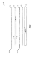
FIG. 2 is a schematic of a liquid leak detection system utilized in the battery pack of -
FIG. 1 in accordance with another exemplary embodiment; -
FIG. 3 is an exploded view of the liquid leak detection system ofFIG. 2 ; -
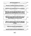
FIG. 4 is a flowchart of a method for detecting a liquid utilizing the liquid leak detection system ofFIG. 2 in accordance with another exemplary embodiment; -
FIG. 5 is a flowchart of a method for manufacturing the battery pack ofFIG. 1 in accordance with another exemplary embodiment; and -
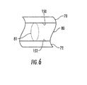
FIG. 6 is a cross-sectional schematic of a portion of the leak detection system ofFIG. 1 . - Referring to
FIG. 1 , abattery pack 10 having aliquid detection system 60 in accordance with an exemplary embodiment is provided. Thebattery pack 10 includesbattery modules liquid coolant system 50, and theliquid detection system 60. - The
liquid coolant system 50 is configured to provide aliquid 81 to the battery modules 20-40 for cooling the battery modules 20-40. - The liquid
leak detection system 60 is configured to detect when a portion of theliquid 81 has leaked from the battery modules 20-40. Referring toFigs. 1 to 3 and6 , theliquid detection system 60 includes electricallyconductive wire grids cell foam layer 80, aninsulating mat 90, atray 100, aresistance measuring device 110, amicroprocessor 120, anelectrical speaker 130, and adisplay device 140. - The electrically
conductive wire grid 70 has a generally rectangular shape and is constructed of an electrically conductive material. In one exemplary embodiment, the electricallyconductive wire grid 70 is constructed of copper. Of course, in alternative embodiments, the electricallyconductive wire grid 70 could be constructed of other metals or metal alloys known to those skilled in the art. Also, in alternative embodiments, the shape of the electricallyconductive wire grid 70 could vary based upon a desired application. As shown, the battery modules 20-40 are disposed on a top portion of the electricallyconductive wire grid 70. - The open-
cell foam layer 80 is disposed between the electricallyconductive wire grids cell foam layer 80 has afirst side 150 and asecond side 152. The electricallyconductive wire grid 70 is disposed on thefirst side 150, and the electricallyconductive wire grid 72 is disposed on thesecond side 152. The open-cell foam layer 80 has a predetermined thickness to allow at least a portion of theliquid 81 contacting the open-cell foam layer 80 to migrate from thefirst side 150 to thesecond side 152. Also, the opencell foam layer 80 has a rectangular shape and defines an area substantially equal to an area of each of the electricallyconductive wire grids - The electrically
conductive wire grid 72 has a generally rectangular shape and is constructed of an electrically conductive material. In one exemplary embodiment, the electricallyconductive wire grid 72 is constructed of copper. Of course, in alternative embodiments, the electricallyconductive wire grid 72 could be constructed of other metals or metal alloys known to those skilled in the art. Also, in alternative embodiments, the shape of the electricallyconductive wire grid 72 could vary based upon a desired application. As shown, the electricallyconductive wire grid 72 is disposed between the open-cell foam layer 80 and theinsulating mat 90. - The insulating
mat 90 is disposed between the electricallyconductive wire grid 72 and thetray 100. In one exemplary embodiment, the insulatingmat 90 is constructed of a rubber compound. Of course, in an alternative embodiment, the insulatingmat 90 could be constructed of other non-electrically conductive materials known to those skilled in the art. - The
tray 100 is configured to hold the insulatingmat 90, the open-cell foam layer 80, and the electricallyconductive wire grids tray 100 hasside walls base plate 164. A height of each of theside walls 160, 161,162, 163 is at least equal to or greater than a height of a stacked assembly of the insulatingmatt 90, the open-cell foam layer 80, and the electricallyconductive wire grids tray 100 is constructed of plastic. - The
resistance measuring device 110 is electrically coupled to the electricallyconductive wire grids electrical conductors resistance measuring device 110 is configured to output a first signal indicative of a resistance level between the electricallyconductive wire grids liquid 81 flows through apertures in the electricallyconductive wire grid 70, the liquid 81 propagates through the open-cell foam layer 80 to the electricallyconductive wire grid 72 and forms a conductive path between thegrids conductive wire grid 70 and propagates through the open-cell foam layer 80 to the electricallyconductive wire grid 72, a resistance level between thegrids grids - The
microprocessor 120 is operably coupled to theresistance measuring device 110, anelectrical speaker 130, and adisplay device 140. Themicroprocessor 120 monitors an output signal from theresistance measuring device 110 to detect a liquid 81 as will be explained in greater detail below. - Referring to
FIGS. 1 ,2 and4 , a flowchart of a method for detecting a liquid 81 leaking from a battery module in accordance with another exemplary embodiment will now be explained. - At
step 190, theresistance measuring device 110 that is disposed below at least one battery module outputs a first signal indicative of a resistance level between electricallyconductive wire grids conductive wire grids cell foam layer 80. - At
step 192, themicroprocessor 120 makes a determination as to whether an amplitude of the first signal is less than or equal to a threshold value, indicating a liquid 81 is detected. If the value ofstep 192 equals "yes", the method advances to step 194. Otherwise, the method returns to step 190. - At
step 194, themicroprocessor 120 outputs a second signal to induce theelectrical speaker 130 to emit a sound indicating that a liquid 81 is detected. - At
step 196, themicroprocessor 120 outputs a third signal to induce thedisplay device 140 to display a first message indicating that the liquid 81 is detected. - Referring to
FIGS. 1 ,2 and5 , a flowchart of a method for manufacturing thebattery pack 10 in accordance with another exemplary embodiment will now be explained. - At
step 210, an operator disposes the insulatingmat 90 in thetray 100. - At
step 212, the operator disposes the electricallyconductive wire grid 72 on the insulatingmat 90. - At
step 214, the operator disposes the open-cell foam layer 80 on the electricallyconductive wire grid 72. - At
step 216, the operator disposes the electricallyconductive wire grid 70 on the open-cell foam layer 80. The open-cell foam layer 80 has a predetermined thickness to allow at least a portion of the liquid 81 contacting the open-cell foam layer 80 to migrate from thefirst side 150 to thesecond side 152. - At
step 218, the operator couples the electricallyconductive wire grids resistance measuring device 110 which is configured to output a first signal indicative of a resistance level between the electricallyconductive wire grids - At
step 220, the operator disposes at least one battery module on the electricallyconductive wire grid 70. The at least one battery module is configured to receive liquid 81 therein for cooling the battery module. - At
step 222, the operator couples themicroprocessor 120 to theresistance measuring device 110. - At
step 224, the operator couples theelectrical speaker 130 and thedisplay device 140 to themicroprocessor 120. - The
battery pack 10 and theliquid detection system 60 provide a substantial advantage over other battery packs and liquid detection systems. In particular, theliquid detection system 60 provides a technical effect of detecting liquid leaking from a battery module utilizing a pair of electrically conductive wire grids separated by an open-cell foam layer. - While the claimed invention has been described in detail in connection with only a limited number of embodiments, it should be readily understood that the invention is not limited to such disclosed embodiments. Rather, the claimed invention can be modified to incorporate any number of variations, alterations, substitutions or equivalent arrangements not heretofore described, but which are commensurate with the spirit and scope of the invention. Additionally, while various embodiments of the claimed invention have been described, it is to be understood that aspects of the invention may include only some of the described embodiments. Accordingly, the claimed invention is not to be seen as limited by the foregoing description.
Claims (12)
- A battery pack, comprising:at least one battery module configured to receive a liquid therein for cooling the battery module; anda liquid leak detection system disposed adjacent to the at least one battery module, the liquid leak detection system comprising:first and second electrically conductive wire grids;an open-cell foam layer having a first side and a second side, the first electrically conductive wire grid disposed on the first side, the second electrically conductive wire grid disposed on the second side, the open-cell foam layer has a predetermined thickness to allow at least a portion of the liquid contacting the open-cell foam layer to migrate from the first side to the second side;an insulating mat disposed between the second electrically conductive wire grid and a tray, the tray being configured to hold the insulating mat, the open-cell foam layer, and the first and second electrically conductive wire grids therein;a resistance measuring device configured to output a first signal indicative of a resistance level between the first and second electrically conductive wire grids; anda microprocessor configured to compare an amplitude of the first signal to a threshold value, the microprocessor further configured to output a second signal if the comparison of the amplitude of the first signal and the threshold value indicates that the liquid is detected.
- The battery pack of claim 1, wherein the comparison of the amplitude of the first signal and the threshold value indicates that the liquid is detected if the amplitude of the first signal is less than or equal to the threshold value.
- The battery pack of claim 1 or 2, wherein the liquid leak detection system further comprises an electrical speaker configured to emit a sound indicating that the liquid is detected in response to receiving the second signal.
- The battery pack of claim 1, 2 or 3, wherein the microprocessor of the liquid leak detection system is further configured to induce a display device to display a first message indicating that the liquid is detected if the comparison of the amplitude of the first signal and the threshold value indicates that the liquid is detected.
- The battery pack of any one of the preceding claims, wherein the open-cell foam layer is an open-cell polyurethane foam layer.
- A liquid leak detection system, comprising:first and second electrically conductive wire grids;an open-cell foam layer having a first side and a second side, the first electrically conductive wire grid disposed on the first side, the second electrically conductive wire grid disposed on the second side, the open-cell foam layer has a predetermined thickness to allow at least a portion of liquid contacting the open-cell foam layer to migrate from the first side to the second side;an insulating mat disposed between the second electrically conductive wire grid and a tray, the tray being configured to hold the insulating mat, the open-cell foam layer, and the first and second electrically conductive wire grids therein;a resistance measuring device configured to output a first signal indicative of a resistance level between the first and second electrically conductive wire grids; anda microprocessor configured to compare an amplitude of the first signal to a threshold value, the microprocessor further configured to output a second signal if the comparison of the amplitude of the first signal and the threshold value indicates that the liquid is detected.
- The liquid leak detection system of claim 6, wherein the comparison of the amplitude of the first signal and the threshold value indicates that the liquid is detected if the amplitude of the first signal is less than or equal to the threshold value.
- The liquid leak detection system of claim 6 or 7, further comprising an electrical speaker configured to emit a sound indicating that the liquid is detected in response to receiving the second signal.
- The liquid leak detection system of claim 6, 7 or 8, wherein the microprocessor is further configured to induce a display device to display a first message indicating that the liquid is detected if the comparison of the amplitude of the first signal and the threshold value indicates that the liquid is detected.
- The liquid leak detection system of any one of the preceding claims 6 to 9, wherein the open-cell foam layer is an open-cell polyurethane foam layer.
- A method for manufacturing a battery pack, comprising:disposing an insulating mat in a tray;disposing a first electrically conductive wire grid on the insulating mat;disposing an open-cell foam layer on the first electrically conductive wire grid;disposing a second electrically conductive wire grid on the open-cell foam layer, the open-cell foam layer has a predetermined thickness to allow at least a portion of a liquid contacting the open-cell foam layer to migrate from the first side to the second side;coupling the first and second electrically conductive wire grids to a resistance measuring device configured to output a first signal indicative of a resistance level between the first and second electrically conductive wire grids; anddisposing at least one battery module on the first electrically conductive wire grid, the at least one battery module configured to receive liquid therein for cooling the battery module.
- The method of claim 11, further comprising coupling a microprocessor to the resistance measuring device.
Applications Claiming Priority (1)
| Application Number | Priority Date | Filing Date | Title |
|---|---|---|---|
| US13/076,774 US20120251859A1 (en) | 2011-03-31 | 2011-03-31 | Battery pack having liquid leak detection system |
Publications (2)
| Publication Number | Publication Date |
|---|---|
| EP2506360A1 true EP2506360A1 (en) | 2012-10-03 |
| EP2506360B1 EP2506360B1 (en) | 2014-06-18 |
Family
ID=46027580
Family Applications (1)
| Application Number | Title | Priority Date | Filing Date |
|---|---|---|---|
| EP20120162506 Active EP2506360B1 (en) | 2011-03-31 | 2012-03-30 | Battery pack having liquid leak detection system |
Country Status (5)
| Country | Link |
|---|---|
| US (1) | US20120251859A1 (en) |
| EP (1) | EP2506360B1 (en) |
| JP (1) | JP5651633B2 (en) |
| KR (1) | KR101306201B1 (en) |
| CN (1) | CN102738532A (en) |
Cited By (4)
| Publication number | Priority date | Publication date | Assignee | Title |
|---|---|---|---|---|
| WO2015097281A1 (en) * | 2013-12-26 | 2015-07-02 | Commissariat à l'énergie atomique et aux énergies alternatives | Electrochemical battery with improved operating safety in moist environments |
| US10050245B2 (en) | 2013-12-26 | 2018-08-14 | Commissariat A L'energie Atomique Et Aux Energies Alternatives | Electrochemical battery module having improved resistance in moist environments and method for producing at least one such module |
| EP3872889A1 (en) | 2020-02-25 | 2021-09-01 | Samsung SDI Co., Ltd. | A battery system, a method for leakage detection inside a battery system and a vehicle including a battery system |
| US11764409B2 (en) | 2020-02-25 | 2023-09-19 | Samsung Sdi Co., Ltd. | Battery system, method for leakage detection inside the battery system, and vehicle including the battery system |
Families Citing this family (26)
| Publication number | Priority date | Publication date | Assignee | Title |
|---|---|---|---|---|
| JP6050814B2 (en) * | 2012-06-15 | 2016-12-21 | 日本碍子株式会社 | Insulated container for assembled battery, controller for assembled battery, and failure detection method for assembled battery |
| US9853330B2 (en) * | 2012-07-10 | 2017-12-26 | GM Global Technology Operations LLC | Enhanced conductive fluid sensor for HV liquid cooled battery packs |
| US10634579B1 (en) | 2013-07-12 | 2020-04-28 | Hill-Rom Services, Inc. | Methods and apparatus for detecting position of a liquid |
| US9719951B1 (en) | 2013-07-12 | 2017-08-01 | Helvetia Wireless Llc | Method and apparatus for moisture detection |
| US11313757B2 (en) | 2013-07-12 | 2022-04-26 | Hill-Rom Services, Inc. | Methods and apparatus for detecting a position of liquid |
| US9448131B2 (en) | 2013-08-27 | 2016-09-20 | Ford Global Technologies, Llc | Battery pack leak detection assembly and method |
| US9625530B2 (en) * | 2014-03-26 | 2017-04-18 | Ford Global Technologies, Llc | Resistance based method and system to assess vehicle component integrity |
| JP2016030246A (en) * | 2014-07-30 | 2016-03-07 | 株式会社イノアックコーポレーション | Liquid absorber |
| US9910003B1 (en) | 2014-12-18 | 2018-03-06 | Helvetia Wireless, Llc | Methods and apparatus for a moisture detector |
| CA2961094A1 (en) | 2016-03-16 | 2017-09-16 | Tti (Macao Commercial Offshore) Limited | Power tool battery pack with wireless communication |
| US10564064B2 (en) * | 2017-02-16 | 2020-02-18 | GM Global Technology Operations LLC | Method of leak testing a low conductivity part |
| KR102324254B1 (en) * | 2017-08-31 | 2021-11-08 | 주식회사 엘지에너지솔루션 | Apparatus for detecting leak and battery pack including the same, vehicle including the same |
| CN108151976A (en) * | 2017-12-12 | 2018-06-12 | 常州普莱德新能源电池科技有限公司 | Apparatus for testing weeping and battery system |
| CN110071310A (en) * | 2018-01-23 | 2019-07-30 | 北京普能世纪科技有限公司 | A kind of conducting liquid battery and its leak detecting device |
| CN110126172A (en) * | 2018-02-09 | 2019-08-16 | 比亚迪股份有限公司 | Pallet production method, pallet and battery pack |
| KR102381655B1 (en) * | 2018-03-21 | 2022-03-31 | 주식회사 엘지에너지솔루션 | Apparatus for detecting coolant leakage |
| DE102018110967A1 (en) * | 2018-05-08 | 2019-11-14 | Dr. Ing. H.C. F. Porsche Aktiengesellschaft | Battery arrangement with cooling unit |
| TWI725422B (en) * | 2018-05-31 | 2021-04-21 | 技嘉科技股份有限公司 | Liquid cooling device, coolant circulation system , and liquid leaking detection method |
| CN109269733B (en) * | 2018-09-14 | 2021-01-05 | 惠州亿纬锂能股份有限公司 | Battery box leakage detection method and system |
| CN109813507B (en) * | 2019-01-30 | 2024-06-11 | 无锡格林司通自动化设备股份有限公司 | Soft package battery leakage inspection method and mechanism |
| KR102051251B1 (en) * | 2019-03-04 | 2019-12-02 | 암페놀센싱코리아 유한회사 | Liquid detection sensor of battery pack for electric vehicles |
| US10859461B2 (en) * | 2019-05-01 | 2020-12-08 | Dell Products, L.P. | Method and apparatus for digital leak detection in liquid-cooled information handling systems |
| CN110207913A (en) * | 2019-07-03 | 2019-09-06 | 北京嘀嘀无限科技发展有限公司 | Hermetization testing method, device and storage medium, the automobile of battery pack |
| FR3109443A1 (en) | 2020-04-16 | 2021-10-22 | Psa Automobiles Sa | FLUID LEAK DETECTION SYSTEM |
| CN113776745A (en) * | 2021-09-14 | 2021-12-10 | 深圳市英维克科技股份有限公司 | Liquid leakage detection sensor and detection system |
| CN218472170U (en) * | 2022-09-30 | 2023-02-10 | 比亚迪股份有限公司 | Battery tray assembly, battery pack and vehicle |
Citations (3)
| Publication number | Priority date | Publication date | Assignee | Title |
|---|---|---|---|---|
| GB776240A (en) * | 1950-06-08 | 1957-06-05 | Chloride Electrical Storage Co | Improvements relating to electric accumulators |
| US4503710A (en) * | 1983-06-08 | 1985-03-12 | Conoco Inc. | Crack detection by electrical resistance |
| GB2442015A (en) * | 2006-09-19 | 2008-03-26 | Francis Bernard Sheehan | Liquid leak detection system |
Family Cites Families (20)
| Publication number | Priority date | Publication date | Assignee | Title |
|---|---|---|---|---|
| JP2777954B2 (en) * | 1992-12-24 | 1998-07-23 | 富士通電装株式会社 | Electrolytic capacitor liquid leak detector |
| JPH0957270A (en) * | 1995-08-30 | 1997-03-04 | Funai Electric Co Ltd | Strongly acidic water generator |
| JP3340983B2 (en) * | 1999-07-27 | 2002-11-05 | 花王株式会社 | Liquid leak inspection system |
| JP2002098610A (en) * | 2000-09-26 | 2002-04-05 | Toto Ltd | Sheet shape detection part of water leakage detector |
| US6731215B2 (en) * | 2000-11-30 | 2004-05-04 | Frederick H. Harms | Moisture monitoring system |
| JP3689053B2 (en) * | 2002-02-20 | 2005-08-31 | 株式会社エヌ・ティ・ティ ファシリティーズ | Battery leakage sensor |
| JP3641258B2 (en) * | 2002-08-26 | 2005-04-20 | 株式会社東芝 | Electronics |
| JP2004247217A (en) * | 2003-02-14 | 2004-09-02 | Toshiba Corp | Electronic equipment and fuel cells used in the equipment |
| JP4843900B2 (en) * | 2004-02-04 | 2011-12-21 | パナソニック株式会社 | Fuel container for fuel cell and fuel cell pack |
| WO2005083410A1 (en) * | 2004-02-26 | 2005-09-09 | Origin Electric Company, Limited | Acid liquid leak sensor |
| JP2005285455A (en) * | 2004-03-29 | 2005-10-13 | Sanyo Electric Co Ltd | Power supply apparatus |
| JP4358170B2 (en) * | 2005-08-30 | 2009-11-04 | 株式会社東芝 | Liquid leak detection structure |
| JP2007273353A (en) * | 2006-03-31 | 2007-10-18 | Toyota Motor Corp | Battery structure |
| US7629067B2 (en) * | 2006-05-22 | 2009-12-08 | Idatech, Llc | Hydrogen-producing fuel processing systems and fuel cell systems with a liquid leak detection system |
| JP5137480B2 (en) * | 2007-06-29 | 2013-02-06 | 三洋電機株式会社 | Power supply for vehicle |
| JP4788674B2 (en) * | 2007-07-05 | 2011-10-05 | トヨタ自動車株式会社 | Power supply |
| JP2009176917A (en) * | 2008-01-24 | 2009-08-06 | Fdk Corp | Nonaqueous electrolyte storage device |
| JP4669533B2 (en) * | 2008-07-02 | 2011-04-13 | 須賀工業株式会社 | Water leakage detection device and water leakage detection system |
| KR101130043B1 (en) * | 2009-07-27 | 2012-03-28 | 주식회사 엘지화학 | Battery Module of Improved Cooling Efficiency |
| US20110217573A1 (en) * | 2010-03-02 | 2011-09-08 | Carl Freudenberg Kg | Sensor for Selectively Detecting Liquids in Apparatuses for Storing and Generating Energy |
-
2011
- 2011-03-31 US US13/076,774 patent/US20120251859A1/en not_active Abandoned
-
2012
- 2012-02-21 KR KR1020120017624A patent/KR101306201B1/en active Active
- 2012-03-30 EP EP20120162506 patent/EP2506360B1/en active Active
- 2012-03-30 JP JP2012079287A patent/JP5651633B2/en active Active
- 2012-03-31 CN CN2012100928726A patent/CN102738532A/en active Pending
Patent Citations (3)
| Publication number | Priority date | Publication date | Assignee | Title |
|---|---|---|---|---|
| GB776240A (en) * | 1950-06-08 | 1957-06-05 | Chloride Electrical Storage Co | Improvements relating to electric accumulators |
| US4503710A (en) * | 1983-06-08 | 1985-03-12 | Conoco Inc. | Crack detection by electrical resistance |
| GB2442015A (en) * | 2006-09-19 | 2008-03-26 | Francis Bernard Sheehan | Liquid leak detection system |
Cited By (5)
| Publication number | Priority date | Publication date | Assignee | Title |
|---|---|---|---|---|
| WO2015097281A1 (en) * | 2013-12-26 | 2015-07-02 | Commissariat à l'énergie atomique et aux énergies alternatives | Electrochemical battery with improved operating safety in moist environments |
| FR3016086A1 (en) * | 2013-12-26 | 2015-07-03 | Commissariat Energie Atomique | ELECTROCHEMICAL BATTERY WITH IMPROVED OPERATING SAFETY IN A WET ENVIRONMENT |
| US10050245B2 (en) | 2013-12-26 | 2018-08-14 | Commissariat A L'energie Atomique Et Aux Energies Alternatives | Electrochemical battery module having improved resistance in moist environments and method for producing at least one such module |
| EP3872889A1 (en) | 2020-02-25 | 2021-09-01 | Samsung SDI Co., Ltd. | A battery system, a method for leakage detection inside a battery system and a vehicle including a battery system |
| US11764409B2 (en) | 2020-02-25 | 2023-09-19 | Samsung Sdi Co., Ltd. | Battery system, method for leakage detection inside the battery system, and vehicle including the battery system |
Also Published As
| Publication number | Publication date |
|---|---|
| JP5651633B2 (en) | 2015-01-14 |
| EP2506360B1 (en) | 2014-06-18 |
| US20120251859A1 (en) | 2012-10-04 |
| KR20120111999A (en) | 2012-10-11 |
| JP2012216541A (en) | 2012-11-08 |
| CN102738532A (en) | 2012-10-17 |
| KR101306201B1 (en) | 2013-09-09 |
Similar Documents
| Publication | Publication Date | Title |
|---|---|---|
| EP2506360A1 (en) | Battery pack having liquid leak detection system | |
| EP3211708B1 (en) | Battery module | |
| JP5489797B2 (en) | Battery system | |
| US9853330B2 (en) | Enhanced conductive fluid sensor for HV liquid cooled battery packs | |
| JP6798982B2 (en) | Battery system and car | |
| US9786894B2 (en) | Battery pack | |
| US20150023392A1 (en) | Battery pack | |
| US11712968B2 (en) | Method for detecting damage to battery pack enclosure during a crash event | |
| CN102680191B (en) | Leakage detection device for power cells | |
| CN103575454B (en) | It is determined that sensor device and method, the electrochemical energy accumulator and its manufacture method of the pressure of medium inside electrochemical energy accumulator | |
| KR102029422B1 (en) | Battery pack temperature detection sensor unit and Monitoring device of energy storage system with the same | |
| CN210723152U (en) | Battery modules, battery packs and vehicles | |
| US9627725B2 (en) | Battery pack | |
| KR101808769B1 (en) | Battery module | |
| KR101750488B1 (en) | Abnormal-temperature Sensing Assembly Comprising Series-connected PTC Thermistors and Battery Pack Comprising the Same | |
| CN202710276U (en) | Power cell liquid leakage detection apparatus | |
| KR102497448B1 (en) | Apparatus and method for determining error of a battery cell | |
| KR20230096912A (en) | Battery module and battery pack and vehicle including the same | |
| US20140242425A1 (en) | Chassis for rechargeable battery | |
| KR101504244B1 (en) | An Apparatus for Detection of Battery swelling and Battery Case Therefor | |
| JP2010114012A (en) | Detecting device of burr of battery electrode plate | |
| JP2015138623A (en) | Method for detecting abnormality of power-storage module, and power-storage module | |
| JP6409389B2 (en) | Power storage device abnormality detection method and power storage device abnormality detection device | |
| CN119779134A (en) | Collision detection device and detection method, battery pack, and electrical equipment | |
| JP2016031891A (en) | Load estimation system |
Legal Events
| Date | Code | Title | Description |
|---|---|---|---|
| PUAI | Public reference made under article 153(3) epc to a published international application that has entered the european phase |
Free format text: ORIGINAL CODE: 0009012 |
|
| 17P | Request for examination filed |
Effective date: 20120330 |
|
| AK | Designated contracting states |
Kind code of ref document: A1 Designated state(s): AL AT BE BG CH CY CZ DE DK EE ES FI FR GB GR HR HU IE IS IT LI LT LU LV MC MK MT NL NO PL PT RO RS SE SI SK SM TR |
|
| AX | Request for extension of the european patent |
Extension state: BA ME |
|
| GRAP | Despatch of communication of intention to grant a patent |
Free format text: ORIGINAL CODE: EPIDOSNIGR1 |
|
| INTG | Intention to grant announced |
Effective date: 20130916 |
|
| RAP1 | Party data changed (applicant data changed or rights of an application transferred) |
Owner name: LG CHEM, LTD. |
|
| GRAS | Grant fee paid |
Free format text: ORIGINAL CODE: EPIDOSNIGR3 |
|
| REG | Reference to a national code |
Ref country code: DE Ref legal event code: R079 Ref document number: 602012002100 Country of ref document: DE Free format text: PREVIOUS MAIN CLASS: H01M0010500000 Ipc: H01M0010600000 |
|
| GRAA | (expected) grant |
Free format text: ORIGINAL CODE: 0009210 |
|
| AK | Designated contracting states |
Kind code of ref document: B1 Designated state(s): AL AT BE BG CH CY CZ DE DK EE ES FI FR GB GR HR HU IE IS IT LI LT LU LV MC MK MT NL NO PL PT RO RS SE SI SK SM TR |
|
| REG | Reference to a national code |
Ref country code: GB Ref legal event code: FG4D |
|
| RIC1 | Information provided on ipc code assigned before grant |
Ipc: H01M 10/60 20140101AFI20140509BHEP Ipc: H01M 2/10 20060101ALI20140509BHEP Ipc: H01M 10/48 20060101ALI20140509BHEP Ipc: H01M 10/42 20060101ALI20140509BHEP |
|
| REG | Reference to a national code |
Ref country code: CH Ref legal event code: EP |
|
| REG | Reference to a national code |
Ref country code: AT Ref legal event code: REF Ref document number: 673824 Country of ref document: AT Kind code of ref document: T Effective date: 20140715 |
|
| REG | Reference to a national code |
Ref country code: IE Ref legal event code: FG4D |
|
| REG | Reference to a national code |
Ref country code: DE Ref legal event code: R096 Ref document number: 602012002100 Country of ref document: DE Effective date: 20140731 |
|
| PG25 | Lapsed in a contracting state [announced via postgrant information from national office to epo] |
Ref country code: CY Free format text: LAPSE BECAUSE OF FAILURE TO SUBMIT A TRANSLATION OF THE DESCRIPTION OR TO PAY THE FEE WITHIN THE PRESCRIBED TIME-LIMIT Effective date: 20140618 Ref country code: LT Free format text: LAPSE BECAUSE OF FAILURE TO SUBMIT A TRANSLATION OF THE DESCRIPTION OR TO PAY THE FEE WITHIN THE PRESCRIBED TIME-LIMIT Effective date: 20140618 Ref country code: FI Free format text: LAPSE BECAUSE OF FAILURE TO SUBMIT A TRANSLATION OF THE DESCRIPTION OR TO PAY THE FEE WITHIN THE PRESCRIBED TIME-LIMIT Effective date: 20140618 Ref country code: NO Free format text: LAPSE BECAUSE OF FAILURE TO SUBMIT A TRANSLATION OF THE DESCRIPTION OR TO PAY THE FEE WITHIN THE PRESCRIBED TIME-LIMIT Effective date: 20140918 Ref country code: GR Free format text: LAPSE BECAUSE OF FAILURE TO SUBMIT A TRANSLATION OF THE DESCRIPTION OR TO PAY THE FEE WITHIN THE PRESCRIBED TIME-LIMIT Effective date: 20140919 |
|
| REG | Reference to a national code |
Ref country code: NL Ref legal event code: VDEP Effective date: 20140618 |
|
| REG | Reference to a national code |
Ref country code: AT Ref legal event code: MK05 Ref document number: 673824 Country of ref document: AT Kind code of ref document: T Effective date: 20140618 |
|
| REG | Reference to a national code |
Ref country code: LT Ref legal event code: MG4D |
|
| PG25 | Lapsed in a contracting state [announced via postgrant information from national office to epo] |
Ref country code: LV Free format text: LAPSE BECAUSE OF FAILURE TO SUBMIT A TRANSLATION OF THE DESCRIPTION OR TO PAY THE FEE WITHIN THE PRESCRIBED TIME-LIMIT Effective date: 20140618 Ref country code: RS Free format text: LAPSE BECAUSE OF FAILURE TO SUBMIT A TRANSLATION OF THE DESCRIPTION OR TO PAY THE FEE WITHIN THE PRESCRIBED TIME-LIMIT Effective date: 20140618 Ref country code: HR Free format text: LAPSE BECAUSE OF FAILURE TO SUBMIT A TRANSLATION OF THE DESCRIPTION OR TO PAY THE FEE WITHIN THE PRESCRIBED TIME-LIMIT Effective date: 20140618 Ref country code: SE Free format text: LAPSE BECAUSE OF FAILURE TO SUBMIT A TRANSLATION OF THE DESCRIPTION OR TO PAY THE FEE WITHIN THE PRESCRIBED TIME-LIMIT Effective date: 20140618 |
|
| PG25 | Lapsed in a contracting state [announced via postgrant information from national office to epo] |
Ref country code: ES Free format text: LAPSE BECAUSE OF FAILURE TO SUBMIT A TRANSLATION OF THE DESCRIPTION OR TO PAY THE FEE WITHIN THE PRESCRIBED TIME-LIMIT Effective date: 20140618 Ref country code: RO Free format text: LAPSE BECAUSE OF FAILURE TO SUBMIT A TRANSLATION OF THE DESCRIPTION OR TO PAY THE FEE WITHIN THE PRESCRIBED TIME-LIMIT Effective date: 20140618 Ref country code: EE Free format text: LAPSE BECAUSE OF FAILURE TO SUBMIT A TRANSLATION OF THE DESCRIPTION OR TO PAY THE FEE WITHIN THE PRESCRIBED TIME-LIMIT Effective date: 20140618 Ref country code: SK Free format text: LAPSE BECAUSE OF FAILURE TO SUBMIT A TRANSLATION OF THE DESCRIPTION OR TO PAY THE FEE WITHIN THE PRESCRIBED TIME-LIMIT Effective date: 20140618 Ref country code: CZ Free format text: LAPSE BECAUSE OF FAILURE TO SUBMIT A TRANSLATION OF THE DESCRIPTION OR TO PAY THE FEE WITHIN THE PRESCRIBED TIME-LIMIT Effective date: 20140618 Ref country code: PT Free format text: LAPSE BECAUSE OF FAILURE TO SUBMIT A TRANSLATION OF THE DESCRIPTION OR TO PAY THE FEE WITHIN THE PRESCRIBED TIME-LIMIT Effective date: 20141020 |
|
| PG25 | Lapsed in a contracting state [announced via postgrant information from national office to epo] |
Ref country code: AT Free format text: LAPSE BECAUSE OF FAILURE TO SUBMIT A TRANSLATION OF THE DESCRIPTION OR TO PAY THE FEE WITHIN THE PRESCRIBED TIME-LIMIT Effective date: 20140618 Ref country code: PL Free format text: LAPSE BECAUSE OF FAILURE TO SUBMIT A TRANSLATION OF THE DESCRIPTION OR TO PAY THE FEE WITHIN THE PRESCRIBED TIME-LIMIT Effective date: 20140618 Ref country code: NL Free format text: LAPSE BECAUSE OF FAILURE TO SUBMIT A TRANSLATION OF THE DESCRIPTION OR TO PAY THE FEE WITHIN THE PRESCRIBED TIME-LIMIT Effective date: 20140618 Ref country code: IS Free format text: LAPSE BECAUSE OF FAILURE TO SUBMIT A TRANSLATION OF THE DESCRIPTION OR TO PAY THE FEE WITHIN THE PRESCRIBED TIME-LIMIT Effective date: 20141018 |
|
| REG | Reference to a national code |
Ref country code: DE Ref legal event code: R097 Ref document number: 602012002100 Country of ref document: DE |
|
| PLBE | No opposition filed within time limit |
Free format text: ORIGINAL CODE: 0009261 |
|
| STAA | Information on the status of an ep patent application or granted ep patent |
Free format text: STATUS: NO OPPOSITION FILED WITHIN TIME LIMIT |
|
| PG25 | Lapsed in a contracting state [announced via postgrant information from national office to epo] |
Ref country code: DK Free format text: LAPSE BECAUSE OF FAILURE TO SUBMIT A TRANSLATION OF THE DESCRIPTION OR TO PAY THE FEE WITHIN THE PRESCRIBED TIME-LIMIT Effective date: 20140618 Ref country code: IT Free format text: LAPSE BECAUSE OF FAILURE TO SUBMIT A TRANSLATION OF THE DESCRIPTION OR TO PAY THE FEE WITHIN THE PRESCRIBED TIME-LIMIT Effective date: 20140618 |
|
| 26N | No opposition filed |
Effective date: 20150319 |
|
| PG25 | Lapsed in a contracting state [announced via postgrant information from national office to epo] |
Ref country code: BE Free format text: LAPSE BECAUSE OF FAILURE TO SUBMIT A TRANSLATION OF THE DESCRIPTION OR TO PAY THE FEE WITHIN THE PRESCRIBED TIME-LIMIT Effective date: 20140618 |
|
| PG25 | Lapsed in a contracting state [announced via postgrant information from national office to epo] |
Ref country code: SI Free format text: LAPSE BECAUSE OF FAILURE TO SUBMIT A TRANSLATION OF THE DESCRIPTION OR TO PAY THE FEE WITHIN THE PRESCRIBED TIME-LIMIT Effective date: 20140618 |
|
| PG25 | Lapsed in a contracting state [announced via postgrant information from national office to epo] |
Ref country code: LU Free format text: LAPSE BECAUSE OF FAILURE TO SUBMIT A TRANSLATION OF THE DESCRIPTION OR TO PAY THE FEE WITHIN THE PRESCRIBED TIME-LIMIT Effective date: 20150330 Ref country code: MC Free format text: LAPSE BECAUSE OF FAILURE TO SUBMIT A TRANSLATION OF THE DESCRIPTION OR TO PAY THE FEE WITHIN THE PRESCRIBED TIME-LIMIT Effective date: 20140618 |
|
| REG | Reference to a national code |
Ref country code: CH Ref legal event code: PL |
|
| REG | Reference to a national code |
Ref country code: IE Ref legal event code: MM4A |
|
| PG25 | Lapsed in a contracting state [announced via postgrant information from national office to epo] |
Ref country code: CH Free format text: LAPSE BECAUSE OF NON-PAYMENT OF DUE FEES Effective date: 20150331 Ref country code: IE Free format text: LAPSE BECAUSE OF NON-PAYMENT OF DUE FEES Effective date: 20150330 Ref country code: LI Free format text: LAPSE BECAUSE OF NON-PAYMENT OF DUE FEES Effective date: 20150331 |
|
| REG | Reference to a national code |
Ref country code: FR Ref legal event code: PLFP Year of fee payment: 5 |
|
| PG25 | Lapsed in a contracting state [announced via postgrant information from national office to epo] |
Ref country code: MT Free format text: LAPSE BECAUSE OF FAILURE TO SUBMIT A TRANSLATION OF THE DESCRIPTION OR TO PAY THE FEE WITHIN THE PRESCRIBED TIME-LIMIT Effective date: 20140618 |
|
| REG | Reference to a national code |
Ref country code: FR Ref legal event code: PLFP Year of fee payment: 6 |
|
| PG25 | Lapsed in a contracting state [announced via postgrant information from national office to epo] |
Ref country code: HU Free format text: LAPSE BECAUSE OF FAILURE TO SUBMIT A TRANSLATION OF THE DESCRIPTION OR TO PAY THE FEE WITHIN THE PRESCRIBED TIME-LIMIT; INVALID AB INITIO Effective date: 20120330 Ref country code: BG Free format text: LAPSE BECAUSE OF FAILURE TO SUBMIT A TRANSLATION OF THE DESCRIPTION OR TO PAY THE FEE WITHIN THE PRESCRIBED TIME-LIMIT Effective date: 20140618 Ref country code: SM Free format text: LAPSE BECAUSE OF FAILURE TO SUBMIT A TRANSLATION OF THE DESCRIPTION OR TO PAY THE FEE WITHIN THE PRESCRIBED TIME-LIMIT Effective date: 20140618 |
|
| PG25 | Lapsed in a contracting state [announced via postgrant information from national office to epo] |
Ref country code: TR Free format text: LAPSE BECAUSE OF FAILURE TO SUBMIT A TRANSLATION OF THE DESCRIPTION OR TO PAY THE FEE WITHIN THE PRESCRIBED TIME-LIMIT Effective date: 20140618 |
|
| REG | Reference to a national code |
Ref country code: FR Ref legal event code: PLFP Year of fee payment: 7 |
|
| PG25 | Lapsed in a contracting state [announced via postgrant information from national office to epo] |
Ref country code: MK Free format text: LAPSE BECAUSE OF FAILURE TO SUBMIT A TRANSLATION OF THE DESCRIPTION OR TO PAY THE FEE WITHIN THE PRESCRIBED TIME-LIMIT Effective date: 20140618 |
|
| PG25 | Lapsed in a contracting state [announced via postgrant information from national office to epo] |
Ref country code: AL Free format text: LAPSE BECAUSE OF FAILURE TO SUBMIT A TRANSLATION OF THE DESCRIPTION OR TO PAY THE FEE WITHIN THE PRESCRIBED TIME-LIMIT Effective date: 20140618 |
|
| REG | Reference to a national code |
Ref country code: DE Ref legal event code: R081 Ref document number: 602012002100 Country of ref document: DE Owner name: LG ENERGY SOLUTION LTD., KR Free format text: FORMER OWNER: LG CHEM. LTD., SEOUL, KR Ref country code: DE Ref legal event code: R081 Ref document number: 602012002100 Country of ref document: DE Owner name: LG ENERGY SOLUTION, LTD., KR Free format text: FORMER OWNER: LG CHEM. LTD., SEOUL, KR |
|
| P01 | Opt-out of the competence of the unified patent court (upc) registered |
Effective date: 20230408 |
|
| REG | Reference to a national code |
Ref country code: GB Ref legal event code: 732E Free format text: REGISTERED BETWEEN 20230824 AND 20230831 |
|
| REG | Reference to a national code |
Ref country code: DE Ref legal event code: R081 Ref document number: 602012002100 Country of ref document: DE Owner name: LG ENERGY SOLUTION, LTD., KR Free format text: FORMER OWNER: LG ENERGY SOLUTION LTD., SEOUL, KR |
|
| PGFP | Annual fee paid to national office [announced via postgrant information from national office to epo] |
Ref country code: GB Payment date: 20260224 Year of fee payment: 15 |
|
| PGFP | Annual fee paid to national office [announced via postgrant information from national office to epo] |
Ref country code: DE Payment date: 20260220 Year of fee payment: 15 |
|
| PGFP | Annual fee paid to national office [announced via postgrant information from national office to epo] |
Ref country code: FR Payment date: 20260224 Year of fee payment: 15 |