EP2506337A1 - Arrangement of battery compartments in a container - Google Patents
Arrangement of battery compartments in a container Download PDFInfo
- Publication number
- EP2506337A1 EP2506337A1 EP12161670A EP12161670A EP2506337A1 EP 2506337 A1 EP2506337 A1 EP 2506337A1 EP 12161670 A EP12161670 A EP 12161670A EP 12161670 A EP12161670 A EP 12161670A EP 2506337 A1 EP2506337 A1 EP 2506337A1
- Authority
- EP
- European Patent Office
- Prior art keywords
- bays
- feet
- length
- storage
- rows
- Prior art date
- Legal status (The legal status is an assumption and is not a legal conclusion. Google has not performed a legal analysis and makes no representation as to the accuracy of the status listed.)
- Granted
Links
- 238000003780 insertion Methods 0.000 claims abstract description 31
- 230000037431 insertion Effects 0.000 claims abstract description 31
- 238000009434 installation Methods 0.000 claims abstract description 21
- HBBGRARXTFLTSG-UHFFFAOYSA-N Lithium ion Chemical compound [Li+] HBBGRARXTFLTSG-UHFFFAOYSA-N 0.000 claims abstract description 5
- 229910001416 lithium ion Inorganic materials 0.000 claims abstract description 5
- 238000006243 chemical reaction Methods 0.000 claims abstract description 4
- 230000000284 resting effect Effects 0.000 claims description 2
- 239000002184 metal Substances 0.000 description 4
- 235000021028 berry Nutrition 0.000 description 3
- 241001080024 Telles Species 0.000 description 2
- 239000004567 concrete Substances 0.000 description 2
- 238000010438 heat treatment Methods 0.000 description 2
- 239000000463 material Substances 0.000 description 2
- 239000002253 acid Substances 0.000 description 1
- 230000032683 aging Effects 0.000 description 1
- 238000004378 air conditioning Methods 0.000 description 1
- 230000007423 decrease Effects 0.000 description 1
- 230000018109 developmental process Effects 0.000 description 1
- 238000004146 energy storage Methods 0.000 description 1
- 238000000605 extraction Methods 0.000 description 1
- RSNHXDVSISOZOB-UHFFFAOYSA-N lithium nickel Chemical compound [Li].[Ni] RSNHXDVSISOZOB-UHFFFAOYSA-N 0.000 description 1
- 230000003137 locomotive effect Effects 0.000 description 1
- 229910052987 metal hydride Inorganic materials 0.000 description 1
- 239000004033 plastic Substances 0.000 description 1
- 230000002787 reinforcement Effects 0.000 description 1
- 239000013589 supplement Substances 0.000 description 1
- 239000002023 wood Substances 0.000 description 1
Images


Classifications
-
- H—ELECTRICITY
- H01—ELECTRIC ELEMENTS
- H01M—PROCESSES OR MEANS, e.g. BATTERIES, FOR THE DIRECT CONVERSION OF CHEMICAL ENERGY INTO ELECTRICAL ENERGY
- H01M10/00—Secondary cells; Manufacture thereof
- H01M10/05—Accumulators with non-aqueous electrolyte
- H01M10/052—Li-accumulators
- H01M10/0525—Rocking-chair batteries, i.e. batteries with lithium insertion or intercalation in both electrodes; Lithium-ion batteries
-
- H—ELECTRICITY
- H01—ELECTRIC ELEMENTS
- H01M—PROCESSES OR MEANS, e.g. BATTERIES, FOR THE DIRECT CONVERSION OF CHEMICAL ENERGY INTO ELECTRICAL ENERGY
- H01M10/00—Secondary cells; Manufacture thereof
- H01M10/42—Methods or arrangements for servicing or maintenance of secondary cells or secondary half-cells
- H01M10/4207—Methods or arrangements for servicing or maintenance of secondary cells or secondary half-cells for several batteries or cells simultaneously or sequentially
-
- H—ELECTRICITY
- H01—ELECTRIC ELEMENTS
- H01M—PROCESSES OR MEANS, e.g. BATTERIES, FOR THE DIRECT CONVERSION OF CHEMICAL ENERGY INTO ELECTRICAL ENERGY
- H01M10/00—Secondary cells; Manufacture thereof
- H01M10/42—Methods or arrangements for servicing or maintenance of secondary cells or secondary half-cells
- H01M10/46—Accumulators structurally combined with charging apparatus
-
- H—ELECTRICITY
- H01—ELECTRIC ELEMENTS
- H01M—PROCESSES OR MEANS, e.g. BATTERIES, FOR THE DIRECT CONVERSION OF CHEMICAL ENERGY INTO ELECTRICAL ENERGY
- H01M50/00—Constructional details or processes of manufacture of the non-active parts of electrochemical cells other than fuel cells, e.g. hybrid cells
- H01M50/20—Mountings; Secondary casings or frames; Racks, modules or packs; Suspension devices; Shock absorbers; Transport or carrying devices; Holders
- H01M50/204—Racks, modules or packs for multiple batteries or multiple cells
-
- Y—GENERAL TAGGING OF NEW TECHNOLOGICAL DEVELOPMENTS; GENERAL TAGGING OF CROSS-SECTIONAL TECHNOLOGIES SPANNING OVER SEVERAL SECTIONS OF THE IPC; TECHNICAL SUBJECTS COVERED BY FORMER USPC CROSS-REFERENCE ART COLLECTIONS [XRACs] AND DIGESTS
- Y02—TECHNOLOGIES OR APPLICATIONS FOR MITIGATION OR ADAPTATION AGAINST CLIMATE CHANGE
- Y02E—REDUCTION OF GREENHOUSE GAS [GHG] EMISSIONS, RELATED TO ENERGY GENERATION, TRANSMISSION OR DISTRIBUTION
- Y02E60/00—Enabling technologies; Technologies with a potential or indirect contribution to GHG emissions mitigation
- Y02E60/10—Energy storage using batteries
Definitions
- the invention relates to the field of transport containers and transportable prefabricated shelters used as a battery storage facility for the use of these batteries as a backup power source, in particular for electrical / electronic equipment in the field. telecommunications field.
- IEC 60297 sets the width of a bay for 482.6 mm (19 inches) to accommodate various electrical / electronic devices, eg batteries.
- the bay has two parallel vertical metal uprights spaced 457.2 mm (18 inches) apart. Holes are drilled at regular intervals on the front of each stud so that they are spaced 18.3 inches (464.82 mm) apart, resulting in a total rack width of 482.6 mm ( 19 inches).
- Devices intended to be installed in such a storage are often referred to as "rack-mountable".
- Their height is usually a multiple of a length named U (for unit) whose dimension has been developed for the Eurocard system.
- a U is 44.45 mm (or 1.75 inches). 1U, 2U, 3U, 4U are common sizes.
- An array with batteries forms an autonomous power source that can be moved and installed near electronic systems that will be powered by these batteries in the event of a mains power failure.
- Several bays may be associated in order to be able to deliver a greater amount of energy to the electronic system.
- the berries can be grouped in a container that is placed on the chassis of a freight train or on a boat to be transported to a given place.
- the document US 2009/0126293 describes a prefabricated shelter with a length between 2.4 and 4.2 m (8 and 14 feet) housing a plurality of racks supporting electronic equipment.
- the bays are arranged along the length of the container in one or two rows.
- DPR TM 15-100C system equipped with lead-acid batteries marketed by Xtreme Power, Inc.
- A123 systems equipped with lithium-ion batteries marketed by A123 Systems, Inc.
- BESS energy storage battery system
- the invention proposes a transportable storage facility (1) having a length of at least 6 m comprising a plurality of bays (2), each bay being intended to contain batteries (3), each bay comprising at least one insertion face of the batteries, at least half of the bays being arranged in such a way that the at least one insertion face is arranged perpendicular to the direction defined by the length of the storage installation, said installation optionally comprising at least one electrical energy conversion device and / or an electronic device for managing a battery.
- the container is a transport container of standardized dimensions, in particular by the ISO TC-104 standard.
- the length can be selected from the following values: 6.1 m (20 feet), 12.2 m (40 feet), 13.7 m (45 feet) and 16.2 m (53 feet).
- the width is 2,438 m (8 feet).
- the height can be chosen from the following values: 2.591 m (8.5 feet), 2.743 m (9 feet) and 2.9 m (9.6 feet).
- At least 75% of the bays are arranged so that said at least one insertion face is disposed perpendicular to the direction defined by the length of the storage facility.
- the Figure 4 is a schematic representation of a container according to the prior art, wherein all the bays are arranged so that their faces for the insertion of the batteries are arranged in the direction along the length of the container.
Abstract
Description
L'invention se rapporte au domaine des conteneurs de transport et des abris préfabriqués transportables utilisés comme installation de stockage de batteries en vue de l'utilisation de ces batteries comme source d'alimentation de secours, en particulier pour des équipements électriques/électroniques dans le domaine des télécommunications.The invention relates to the field of transport containers and transportable prefabricated shelters used as a battery storage facility for the use of these batteries as a backup power source, in particular for electrical / electronic equipment in the field. telecommunications field.
On connaît des batteries conçues à partir d'éléments électrochimiques de type lithium-ion ou nickel-hydrure métallique destinées à servir de source d'alimentation de secours pour les réseaux de télécommunication basse tension (24 à 48 V). Ces batteries peuvent être disposées dans un bâti modulaire, encore appelé baie ou « rack », dont la largeur est normalisée à 482,6 mm (19 pouces). Chaque baie peut contenir plusieurs batteries délivrant chacune 48 V. Un convertisseur de courant continu en courant alternatif (DC/AC) permet de convertir le courant continu généré par les batteries en un courant alternatif utilisable pour l'alimentation des systèmes électroniques des réseaux de télécommunication. On pourra se reporter au site www.saftbatteries.com qui donne de plus amples informations sur ce type de sources d'alimentation de secours, en particulier les systèmes batteries de la gamme Intensium.Batteries designed from lithium-ion or nickel-metal hydride electrochemical cells are known for use as back-up power sources for low-voltage telecommunication networks (24 to 48 V). These batteries can be arranged in a modular frame, also called rack or "rack", whose width is normalized to 482.6 mm (19 inches). Each rack can contain several batteries, each delivering 48 V. A DC converter (DC / AC) is used to convert the direct current generated by the batteries into an alternating current that can be used to power the electronic systems of telecommunication networks. . See www.saftbatteries.com for more information on this type of back-up power source, particularly the Intensium range of battery systems.
La norme CEI 60297 fixe à 482,6 mm (19 pouces) la largeur d'une baie destinée à recevoir divers appareils électriques/électroniques, par exemples des batteries. La baie comprend deux montants verticaux parallèles en métal espacés de 457,2 mm (soit 18 pouces). Des trous sont forés à intervalles réguliers sur la partie frontale de chaque montant de manière à ce qu'ils soient espacés de 464,82 mm (soit 18,3 pouces), ce qui donne une largeur totale de baie de 482,6 mm (soit 19 pouces). Les appareils destinés à être installés dans un tel rangement sont souvent qualifiés de « rackables ». Leur hauteur est habituellement un multiple d'une longueur nommée U (pour unité) dont la dimension a été développée pour le système Eurocard. Un U vaut 44,45 mm (soit 1,75 pouces). 1U, 2U, 3U, 4U sont des tailles courantes.IEC 60297 sets the width of a bay for 482.6 mm (19 inches) to accommodate various electrical / electronic devices, eg batteries. The bay has two parallel vertical metal uprights spaced 457.2 mm (18 inches) apart. Holes are drilled at regular intervals on the front of each stud so that they are spaced 18.3 inches (464.82 mm) apart, resulting in a total rack width of 482.6 mm ( 19 inches). Devices intended to be installed in such a storage are often referred to as "rack-mountable". Their height is usually a multiple of a length named U (for unit) whose dimension has been developed for the Eurocard system. A U is 44.45 mm (or 1.75 inches). 1U, 2U, 3U, 4U are common sizes.
Une baie équipée de batteries forme une source d'énergie autonome qui peut être déplacée et installée à proximité de systèmes électroniques qui seront alimentés par ces batteries en cas de coupure de courant du secteur. Plusieurs baies peuvent être associées afin de pouvoir délivrer une plus forte quantité d'énergie au système électronique. Les baies peuvent être regroupées dans un conteneur qui est placé sur le châssis d'un train de marchandises ou sur un bateau afin d'être transporté vers un lieu donné.An array with batteries forms an autonomous power source that can be moved and installed near electronic systems that will be powered by these batteries in the event of a mains power failure. Several bays may be associated in order to be able to deliver a greater amount of energy to the electronic system. The berries can be grouped in a container that is placed on the chassis of a freight train or on a boat to be transported to a given place.
Dans le domaine du transport, un conteneur est un caisson métallique, en forme de parallélépipède, conçu pour le transport de marchandises par différents modes de transport, tel que le transport par voie maritime. Ses dimensions ont été normalisées au niveau international. Selon la norme ISO, il existe trois grandes séries de conteneurs de largeur et de hauteur fixées mais de longueur variable. Les dimensions extérieures standards sont :
- longueurs de 6,058 m (20 pieds), 9,087 m (30 pieds), 12,192 m (40 pieds) ;
- largeur de 2,438 m (8 pieds) ;
- hauteurs de 2,591 m (8,5 pieds), 2,743 m (9 pieds) et 2,9 m (9,6 pieds).
- lengths of 6.058 m (20 feet), 9.087 m (30 feet), 12.192 m (40 feet);
- width of 2,438 m (8 feet);
- heights of 2.591 m (8.5 feet), 2.763 m (9 feet) and 2.9 m (9.6 feet).
Tous les conteneurs de ces trois séries ont la même largeur, 2,438 m (8 pieds), ce qui a permis le développement de navires porte-conteneurs. Les dimensions intérieures standards sont :
- longueur de 5,905 m (20 pieds), 12,04 m (40 pieds) ;
- largeur de 2,33 m ;
- hauteur de 2,38 m ;
- hauteur passage de
porte 2,30 m.
- length of 5.905 m (20 feet), 12.04 m (40 feet);
- width of 2.33 m;
- height of 2.38 m;
- door passage height 2.30 m.
Le document
Le document
Dans les systèmes d'alimentation de secours utilisant un conteneur comme installation de stockage de batteries, les baies sont disposées dans le sens de la longueur du conteneur sur une ou deux rangées. On pourra par exemple se référer au système DPR™ 15-100C équipé de batteries au plomb, commercialisé par la société Xtreme Power, Inc., aux systèmes A123 équipés de batteries de type lithium-ion, commercialisés par la société A123 Systems, Inc. et au système de stockage d'énergie par batteries (BESS) présenté au 11ème congrès ELBC (European Lead Battery Conference) à Istanbul, le 24 septembre 2010. Or, une telle disposition des baies ne permet pas d'obtenir une densité énergétique suffisante.In backup power systems using a container as a battery storage facility, the bays are arranged along the length of the container in one or two rows. For example, reference can be made to the DPR ™ 15-100C system equipped with lead-acid batteries, marketed by Xtreme Power, Inc., to A123 systems equipped with lithium-ion batteries, marketed by A123 Systems, Inc. and energy storage battery system (BESS) presented at the 11th Congress ELBC (European Lead battery Conference) in Istanbul on 24 September 2010. However, such a provision berries do not provide sufficient energy density .
On cherche donc une disposition de baies dans une installation de stockage transportable qui permette d'augmenter le nombre de baies par unité de surface dans ladite installation de stockage transportable. L'augmentation du nombre de baies permet d'augmenter l'énergie surfacique. En particulier, on cherche à augmenter le nombre de baies par unité de surface d'un conteneur de dimensions normalisées. En particulier, on cherche à augmenter le nombre de baies d'une largeur de 482,6 mm (19 pouces) dans un conteneur de dimensions normalisées, par exemple de 6,1 m (20 pieds), de 12,2 m (40 pieds), de 13,7 m (45 pieds) ou de 16,2 m (53 pieds) de longueur.We are therefore looking for an arrangement of bays in a transportable storage facility that increases the number of bays per unit area in said transportable storage facility. The increase in the number of bays makes it possible to increase the surface energy. In particular, it is sought to increase the number of bays per unit area of a container of standardized dimensions. In particular, it is sought to increase the number of racks with a width of 482.6 mm (19 inches) in a container of standardized dimensions, for example of 6.1 m (20 feet), 12.2 m (40 feet), 13.7 m (45 feet) or 16.2 m (53 feet) in length.
A cet effet, l'invention propose une installation de stockage (1) transportable d'une longueur d'au moins 6 m comprenant une pluralité de baies (2), chaque baie étant destinée à contenir des batteries (3), chaque baie comprenant au moins une face d'insertion des batteries, la moitié au moins des baies étant disposées de manière à ce que ladite au moins une face d'insertion soit disposée perpendiculairement à la direction définie par la longueur de l'installation de stockage, ladite installation comprenant éventuellement au moins un dispositif de conversion d'énergie électrique et/ou un dispositif électronique de gestion d'une batterie.For this purpose, the invention proposes a transportable storage facility (1) having a length of at least 6 m comprising a plurality of bays (2), each bay being intended to contain batteries (3), each bay comprising at least one insertion face of the batteries, at least half of the bays being arranged in such a way that the at least one insertion face is arranged perpendicular to the direction defined by the length of the storage installation, said installation optionally comprising at least one electrical energy conversion device and / or an electronic device for managing a battery.
On entend par face d'insertion de la baie, le côté de la baie par lequel on introduit une batterie pour la loger à l'intérieur de la baie. La face d'insertion est généralement définie par le plan formé par les deux montants verticaux qui servent à fixer la batterie à la baie. La face d'insertion sert aussi de face d'extraction de la batterie.By insertion side of the bay is meant the side of the bay by which a battery is inserted to house it inside the bay. The insertion face is generally defined by the plane formed by the two vertical uprights which serve to fix the battery to the bay. The insertion face also serves as the extraction face of the battery.
La baie peut ne pas comprendre de montants verticaux servant d'armature et être essentiellement constituée d'un plateau horizontal à la surface duquel sont disposés des moyens de fixation de la batterie au plateau horizontal. Dans ce cas, la face d'insertion est le côté du plateau qui permet d'amener la batterie en contact des éléments de fixation.The bay may not include vertical uprights for armature and consist essentially of a horizontal plate on the surface of which are arranged means for fixing the battery to the horizontal plate. In this case, the insertion face is the side of the plate which makes it possible to bring the battery into contact with the fixing elements.
Autrement dit, l'invention consiste à disposer les baies dans le sens transversal de l'installation de stockage. L'installation de stockage transportable est de préférence un conteneur de transport ou un abri préfabriqué.In other words, the invention consists in arranging the bays in the transverse direction of the storage facility. The transportable storage facility is preferably a transport container or prefabricated shelter.
Selon un mode de réalisation, le conteneur est un conteneur de transport de dimensions normalisées, en particulier par la norme ISO TC-104. La longueur peut être choisie parmi les valeurs suivantes : 6,1 m (20 pieds), 12,2 m (40 pieds), 13,7 m (45 pieds) et 16,2 m (53 pieds). La largeur est de 2,438 m (8 pieds). La hauteur peut être choisie parmi les valeurs suivantes : 2,591 m (8,5 pieds), 2,743 m (9 pieds) et 2,9 m (9,6 pieds).According to one embodiment, the container is a transport container of standardized dimensions, in particular by the ISO TC-104 standard. The length can be selected from the following values: 6.1 m (20 feet), 12.2 m (40 feet), 13.7 m (45 feet) and 16.2 m (53 feet). The width is 2,438 m (8 feet). The height can be chosen from the following values: 2.591 m (8.5 feet), 2.743 m (9 feet) and 2.9 m (9.6 feet).
Selon un mode de réalisation, au moins 75% des baies sont disposées de manière à ce que ladite au moins une face d'insertion soit disposée perpendiculairement à la direction définie par la longueur de l'installation de stockage.According to one embodiment, at least 75% of the bays are arranged so that said at least one insertion face is disposed perpendicular to the direction defined by the length of the storage facility.
Selon un mode de réalisation, toutes les baies sont disposées de manière à ce que ladite au moins une face d'insertion soit disposée perpendiculairement à la direction définie par la longueur de l'installation de stockage.According to one embodiment, all the bays are arranged so that said at least one insertion face is disposed perpendicular to the direction defined by the length of the storage facility.
Selon un mode de réalisation, les dimensions de chaque baie sont normalisées, en particulier par la norme CEI 60297. La largeur de chaque baie est de 482,6 mm (19 pouces).According to one embodiment, the dimensions of each bay are standardized, in particular by the IEC 60297 standard. The width of each bay is 482.6 mm (19 inches).
Selon un mode de réalisation, l'installation de stockage comprend au moins deux rangées de baies disposées perpendiculairement à la direction définie par la longueur de l'installation de stockage et il existe au moins un couloir de circulation entre ces deux rangées de baies.According to one embodiment, the storage facility comprises at least two rows of bays arranged perpendicularly to the direction defined by the length of the storage facility and there is at least one traffic corridor between these two rows of bays.
Selon un mode de réalisation, l'installation de stockage transportable comprend au moins une rangée de 4 baies.According to one embodiment, the transportable storage installation comprises at least one row of 4 bays.
Selon un mode de réalisation, l'installation de stockage a une longueur de 6,1 m (20 pieds) et comprend 6 rangées de 4 baies.According to one embodiment, the storage facility has a length of 6.1 m (20 feet) and comprises 6 rows of 4 bays.
Selon un mode de réalisation, l'installation de stockage a une longueur de 6,1 m (20 pieds) et comprend 4 rangées de 4 baies et 2 rangées de 2 baies.According to one embodiment, the storage facility has a length of 6.1 m (20 feet) and comprises 4 rows of 4 bays and 2 rows of 2 bays.
Selon un mode de réalisation, l'installation de stockage a une longueur de 12,2 m (40 pieds) et comprend 12 rangées de 4 baies.According to one embodiment, the storage facility is 12.2 m (40 feet) long and comprises 12 rows of 4 bays.
Selon un mode de réalisation, l'installation de stockage a une longueur de 12,2 m (40 pieds) et comprend 8 rangées de 4 baies, deux rangées de 2 baies et deux rangées de 3 baies dont au moins une face pour l'insertion des batteries est disposée selon la direction de la longueur de l'installation.According to one embodiment, the storage facility has a length of 12.2 m (40 feet) and comprises 8 rows of 4 bays, two rows of 2 bays and two rows of 3 bays, at least one side for the insertion of the batteries is arranged in the direction of the length of the installation.
Selon un mode de réalisation, l'installation de stockage est de format parallélépipédique, et au moins une paroi latérale située dans la direction définie par la longueur de l'installation de stockage comprend au moins une ouverture.According to one embodiment, the storage facility is of parallelepipedal format, and at least one side wall in the direction defined by the length of the storage facility comprises at least one opening.
Selon un mode de réalisation, l'installation de stockage comprend des batteries, de préférence de type lithium-ion.According to one embodiment, the storage installation comprises batteries, preferably of lithium-ion type.
L'invention a également pour objet un ensemble formé par un empilement d'au moins deux installations de stockage selon l'invention.The invention also relates to an assembly formed by a stack of at least two storage facilities according to the invention.
L'invention a également pour objet un ensemble formé par la juxtaposition d'au moins deux installations de stockage reposant sur une même surface.The invention also relates to an assembly formed by the juxtaposition of at least two storage facilities resting on the same surface.
-
La
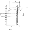
Figure 1 est une représentation schématique d'une batterie (3) et son montage sur une baie (2) de 482,6 mm (19 pouces).TheFigure 1 is a schematic representation of a battery (3) and its mounting on a rack (2) of 482.6 mm (19 inches). -
La
Figure 2 est une représentation schématique d'un conteneur (1) de 6,1 m (20 pieds) dans lequel la disposition des baies (2) est selon l'invention. Le conteneur présente 4 rangées de 4 baies et 2 rangées de 2 baies.TheFigure 2 is a schematic representation of a container (1) of 6.1 m (20 feet) in which the arrangement of the racks (2) is according to the invention. The container has 4 rows of 4 bays and 2 rows of 2 bays. -
La
Figure 3 est une représentation schématique d'un conteneur (1) de 12,2 m (40 pieds) dans lequel la disposition des baies (2) est selon l'invention. Il présente 8 rangées de 4 baies, 2 rangées de 2 baies et 2 rangées de 3 baies disposées contre la paroi latérale du conteneur.TheFigure 3 is a schematic representation of a container (1) 12.2 m (40 feet) in which the arrangement of the racks (2) is according to the invention. It has 8 rows of 4 bays, 2 rows of 2 bays and 2 rows of 3 bays arranged against the side wall of the container. -
La
Figure 4 est une représentation schématique d'un conteneur (1) selon l'art antérieur vu de dessus, dans lequel toutes les baies (2) sont disposées de manière à ce que leurs faces d'insertion des batteries soient disposées selon la longueur du conteneur (disposition A).TheFigure 4 is a schematic representation of a container (1) according to the prior art seen from above, in which all the bays (2) are arranged in such a way that their insertion faces of the batteries are arranged along the length of the container ( provision A). -
La
Figure 5 est une représentation schématique d'un conteneur (1) selon l'invention vu de dessus, dans lequel toutes les baies (2) sont disposées de manière à ce que les faces pour l'insertion des batteries soient disposées selon la largeur du conteneur (disposition B). La largeur des baies est de 482,6 mm (19 pouces).TheFigure 5 is a diagrammatic representation of a container (1) according to the invention seen from above, in which all the bays (2) are arranged in such a way that the faces for the insertion of the batteries are arranged according to the width of the container ( provision B). The width of the racks is 482.6 mm (19 inches). -
La
Figure 6 est une représentation schématique d'un conteneur (1) selon l'invention vu de dessus, dans lequel :- 75% des baies (2) sont disposées de manière à ce que les faces pour l'insertion des batteries soient disposées selon la largeur du conteneur;
- 25% des baies (2) sont disposées de manière à ce que les faces pour l'insertion des batteries soient disposées selon la longueur du conteneur. (disposition C).
Figure 6 is a schematic representation of a container (1) according to the invention seen from above, in which:- 75% of the bays (2) are arranged so that the faces for the insertion of the batteries are arranged according to the width of the container;
- 25% of the bays (2) are arranged so that the faces for the insertion of the batteries are arranged along the length of the container. (provision C).
Dans les
- La
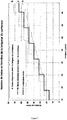
Figure 7 représente le nombre de baies qu'il est possible de loger dans un conteneur en fonction de leur disposition : disposition A selon l'art antérieur telle que représentée à laFigure 4 ; dispositions B et C selon l'invention telles que représentées auxFigures 5 et 6 . - La
Figure 8 représente une vue de dessus d'un champ d'exploitation dans lequel sont installés six conteneurs selon l'invention d'une longueur de 6,1 m (20 pieds), pouvant délivrer chacun une énergie de 560 kW.h. - La
Figure 9 représente une vue de dessus d'un champ d'exploitation dans lequel sont installés trois conteneurs selon l'invention d'une longueur de 12,2 m (40 pieds), pouvant délivrer chacun une énergie de 1200 kW.h. - La
Figure 10 représente une vue de dessus d'un champ d'exploitation dans lequel sont installés six conteneurs selon l'art antérieur d'une longueur de 16,2 m (53 pieds), pouvant délivrer chacun une énergie de 500 kW.h.
- The
Figure 7 represents the number of bays that can be accommodated in a container according to their disposition: arrangement A according to the prior art as represented in FIG.Figure 4 ; provisions B and C according to the invention as represented inFigures 5 and 6 . - The
Figure 8 represents a top view of an operating field in which six containers according to the invention of a length of 6.1 m (20 feet) are installed, each capable of delivering an energy of 560 kW.h. - The
Figure 9 represents a top view of an operating field in which are installed three containers according to the invention of a length of 12.2 m (40 feet), each capable of delivering an energy of 1200 kW.h. - The
Figure 10 represents a top view of an operating field in which are installed six containers according to the prior art of a length of 16.2 m (53 feet), each capable of delivering an energy of 500 kW.h.
Dans l'invention, on désigne par le terme de batterie l'association de plusieurs générateurs électrochimiques en une configuration série et/ou parallèle, déterminée en fonction de la tension nominale et de la quantité d'énergie (W.h) désirées pour alimenter l'application électrique. Les générateurs électrochimiques sont placés dans un boîtier commun et l'on désigne l'ensemble par le terme de batterie. Plusieurs batteries peuvent être empilées dans une baie. Des normes définissent les dimensions des baies pouvant recevoir les batteries. On peut citer sans être limitatif, les normes CEI 60297, CEI 60917, CEI 61969 et ETS 300 119-3 (European Telecommunication Standard).In the invention, the term "battery" refers to the combination of several electrochemical generators in a series and / or parallel configuration, determined as a function of the nominal voltage and the quantity of energy (Wh) desired to power the generator. electrical application. The electrochemical generators are placed in a common housing and is designated together by the term battery. Several batteries can be stacked in a bay. Standards define the dimensions of the bays that can receive the batteries. The following can be cited without limitation: IEC 60297, IEC 60917, IEC 61969 and ETS 300 119-3 (European Telecommunication Standard).
Par exemple, la norme CEI 60297 spécifie une largeur de baie de 482,6 mm (19 pouces).For example, IEC 60297 specifies a rack width of 482.6 mm (19 inches).
La
La batterie présente la forme d'un parallélépipède. Sa largeur L' peut être égale à 482,6 mm (19 pouces) moins la largeur des deux montants verticaux qui servent d'armature de la baie, soit dans la plage allant généralement de 406,4 à 457,2 mm (16 à 18 pouces). Une largeur égale à la moitié de la largeur de la baie est également envisageable, soit une largeur dans la plage allant de 203,2 à 228,6 mm (8 à 9 pouces).The battery has the shape of a parallelepiped. Its width L 'may be equal to 482.6 mm (19 inches) less the width of the two vertical uprights which serve as reinforcement of the bay, or in the range generally from 406.4 to 457.2 mm (16 to 18 inches). A width equal to half the width of the bay is also conceivable, a width in the range of 203.2 to 228.6 mm (8 to 9 inches).
La batterie comporte typiquement sur une de ses faces une plaque de largeur 482,6 mm (19 pouces) qui comprend généralement un interrupteur, des voyants indiquant à l'opérateur l'état de charge de la batterie, l'état de vieillissement de la batterie, ainsi que des connecteurs pour l'acquisition de données relatives au fonctionnement de la batterie. La plaque peut comprendre à chacune de ses extrémités un moyen de fixation de la batterie aux deux montants verticaux de la baie.The battery typically has on one of its faces a plate of width 482.6 mm (19 inches) which generally comprises a switch, lights indicating to the operator the state of charge of the battery, the state of aging of the battery. battery, as well as connectors for acquiring data relating to the operation of the battery. The plate may comprise at each of its ends a means of fixing the battery to the two vertical uprights of the bay.
Comme indiqué plus haut, la face d'insertion est constituée par le plan passant par les deux montants verticaux de la baie. Une fois la batterie fixée aux deux montants verticaux, la plaque comprenant les indicateurs donnant les informations sur le fonctionnement de la batterie est donc située sur la face d'insertion de la batterie.As indicated above, the insertion face is constituted by the plane passing through the two vertical uprights of the bay. Once the battery is attached to the two uprights, the plate including the indicators giving the information on the operation of the battery is located on the insertion side of the battery.
La hauteur H de la batterie est généralement un multiple d'une longueur nommée U (pour unité) dont la dimension a été développée pour le système Eurocard. Un U vaut 44,45 mm (1,75 pouces). 1U (44,45 mm), 2U (88,9 mm), 3U (133,35 mm) et 4U (177,8 mm) sont des hauteurs possibles.The height H of the battery is generally a multiple of a length named U (for unit) whose dimension has been developed for the Eurocard system. A U is 44.45 mm (1.75 inches). 1U (44.45mm), 2U (88.9mm), 3U (133.35mm) and 4U (177.8mm) are possible heights.
La profondeur P de la batterie ne répond pas à des limitations particulières. Les baies équipées des batteries sont ensuite installées dans une installation de stockage transportable, telle qu'un conteneur ou un abri préfabriqué. Un conteneur est généralement constitué de l'assemblage de plusieurs panneaux de métal ce qui lui confère une grande solidité. En raison de leur solidité, plusieurs conteneurs peuvent être superposés. Les dimensions du conteneur satisfont de préférence aux exigences de la norme ISO TC-104. La longueur du conteneur peut prendre les valeurs suivantes : 6,1 m (20 pieds), 12,2 m (40 pieds), 13,7 m (45 pieds) et 16,2 m (53 pieds). La largeur est de 2,438 m (8 pieds). La hauteur du conteneur peut prendre les valeurs suivantes 2,591 m (8,5 pieds), 2,743 m (9 pieds) et 2,9 m (9,6 pieds).The depth P of the battery does not respond to particular limitations. The bays equipped with the batteries are then installed in a transportable storage facility, such as a container or a prefabricated shelter. A container is generally made of the assembly of several metal panels which gives it great strength. Because of their strength, several containers can be stacked. The dimensions of the container preferably meet the requirements of ISO TC-104. The length of the container can be as follows: 6.1 m (20 feet), 12.2 m (40 feet), 13.7 m (45 feet) and 16.2 m (53 feet). The width is 2,438 m (8 feet). The height of the container may be 2.591 m (8.5 feet), 2.743 m (9 feet) and 2.9 m (9.6 feet).
Un abri préfabriqué est obtenu par l'assemblage de panneaux de matériaux divers, tels que le béton, le métal, le bois, et les matériaux plastiques. Ses dimensions peuvent être normalisées. Par exemple, la largeur peut être normalisée à 2,4 m, ce qui correspond au gabarit routier. Il est précisé que l'installation de stockage transportable peut être déplacée d'un lieu à un autre, par exemple par voie routière, par voie ferrée ou par voie maritime et que lors du transport, les batteries sont stockées dans l'installation et sont disposées selon l'invention. L'installation de stockage transportable peut être un abri préfabriqué en béton, aux normes du transport routier, qui se transporte et contient pendant le transport, des batteries agencées selon la disposition décrite ci-après.A prefabricated shelter is obtained by assembling panels of various materials, such as concrete, metal, wood, and plastic materials. Its dimensions can be standardized. For example, the width can be normalized to 2.4 m, which corresponds to the road gauge. It is specified that the transportable storage facility may be moved from one place to another, for example by road, rail or sea and that during transport the batteries are stored in the installation and are disposed according to the invention. The transportable storage facility may be a prefabricated concrete shelter, to road transport standards, which is transported and contains during transport, batteries arranged in the arrangement described below.
Selon l'invention, on installe chaque baie dans l'installation de stockage transportable de manière à ce que les faces d'insertion des batteries soient disposées perpendiculairement à la direction définie par la longueur de l'installation de stockage. Cette disposition permet une densité d'énergie plus importante que pour une disposition dans la direction selon la longueur de l'installation de stockage.According to the invention, each rack is installed in the transportable storage installation so that the insertion faces of the batteries are arranged perpendicular to the direction defined by the length of the storage facility. This arrangement allows a higher energy density than for a disposition in the direction according to the length of the storage facility.
Plusieurs installations de stockage peuvent être soit empilées les unes sur les autres, soient accolées et reposer sur une même surface.Several storage facilities can be stacked on top of each other, contiguous and rest on the same surface.
Pour un conteneur d'une largeur normalisée à 2,4 m (8 pieds), on peut regrouper les baies pour former une rangée de 4 baies dont la longueur totale est de 4×19 pouces = 76 pouces soit 1,93 m. Un tel alignement occupe pratiquement toute la largeur interne du conteneur qui est normalisée à 2,33 m.For a container with a standard width of 2.4 m (8 feet), the racks can be grouped together to form a row of 4 bays with a total length of 4 × 19 inches = 76 inches or 1.93 m. Such alignment occupies virtually the entire internal width of the container which is normalized to 2.33 m.
Un conteneur long de 6,1 m (20 pieds) peut recevoir par exemple 6 rangées de 4 baies. On peut également prévoir de ménager un espace libre pour le stockage par exemple d'un équipement anti-incendie, en créant 4 rangées de 4 baies et 2 rangées de 2 baies tel qu'illustré à la
Un conteneur long de 12,2 m (40 pieds) peut recevoir par exemple :
- 12 rangées de 4 baies ou
- 8 rangées de 4 baies, 2 rangées de 2 baies et 2 rangées de 3 baies disposées contre la paroi latérale du conteneur dans le sens de la longueur du conteneur. Ce mode de réalisation est illustré
Figure 3 .
- 12 rows of 4 bays or
- 8 rows of 4 bays, 2 rows of 2 bays and 2 rows of 3 bays arranged against the side wall of the container in the direction of the length of the container. This embodiment is illustrated
Figure 3 .
De préférence, l'installation de stockage comprend au moins un dispositif de conversion d'énergie tel qu'un tel qu'un onduleur, un transformateur, un chargeur, un convertisseur tel qu'un convertisseur de courant continu - courant continu (DC/DC), un convertisseur de courant continu - courant alternatif (DC/AC), un convertisseur de courant alternatif - courant continu (AC/DC) ou un convertisseur de courant alternatif - courant alternatif (AC/AC).Preferably, the storage facility comprises at least one energy conversion device such as an inverter, a transformer, a charger, a converter such as a DC-DC converter (DC / DC), AC / DC converter, AC / DC converter or AC / AC converter.
Ces dispositifs peuvent être de dimensions diverses. Dans certains cas, ces dispositifs sont dans des armoires qui peuvent être disposées comme les baies de l'invention. Dans d'autres cas, leurs dimensions ne sont pas normalisées.These devices can be of various sizes. In some cases, these devices are in cabinets that can be arranged as the bays of the invention. In other cases, their dimensions are not standardized.
La
La
La
- 75% des baies sont disposées de manière à ce que leurs faces pour l'insertion des batteries soient disposées perpendiculairement à la direction définie par la longueur du conteneur;
- 25% des batteries sont disposées de manière à ce que leurs faces pour l'insertion des batteries soient disposées selon la direction définie par la longueur du conteneur.
- 75% of the bays are arranged so that their faces for the insertion of the batteries are arranged perpendicular to the direction defined by the length of the container;
- 25% of the batteries are arranged so that their faces for the insertion of the batteries are arranged in the direction defined by the length of the container.
La
Un des avantages de l'invention est que chaque face de la baie est disponible à l'opérateur, ce qui n'est pas le cas dans la disposition de l'art antérieur dans laquelle l'une des deux faces de la baie repose contre une des parois latérales du conteneur. Selon l'invention, comme les deux faces de la baie sont disponibles, on réduit le nombre de baies et donc leur coût.One of the advantages of the invention is that each face of the bay is available to the operator, which is not the case in the provision of the prior art in which one of the two faces of the bay rests against one of the side walls of the container. According to the invention, as the two faces of the bay are available, it reduces the number of bays and therefore their cost.
Un avantage supplémentaire de la disposition selon l'invention est que des couloirs de circulation sont crées entre deux rangées de baies disposées dans le sens de la largeur du conteneur. Ils sont de la largeur minimale autorisée par les normes et nécessitent l'ouverture de portes dans la paroi latérale du conteneur. Ils permettent à un opérateur de contrôler le fonctionnement des batteries.An additional advantage of the arrangement according to the invention is that traffic corridors are created between two rows of bays arranged in the width direction of the container. They are of the minimum width allowed by the standards and require the opening of doors in the side wall of the container. They allow an operator to control the operation of the batteries.
Un avantage supplémentaire de la disposition selon l'invention est la réduction de l'échauffement à l'intérieur du conteneur. En effet, à quantité d'énergie égale, la réduction de la taille du conteneur à 12,2 m (20 pieds) permet de réduire l'échauffement du conteneur par le soleil. On peut donc réduire la puissance de climatisation de l'intérieur du conteneur. Le transport du conteneur est également plus facile.An additional advantage of the arrangement according to the invention is the reduction of the heating inside the container. Indeed, for equal amount of energy, reducing the size of the container to 12.2 m (20 feet) reduces the heating of the container by the sun. It is therefore possible to reduce the air conditioning power of the interior of the container. Transport of the container is also easier.
Un avantage supplémentaire de la disposition selon l'invention est qu'en raison de la diminution de la taille conteneur, il est possible d'installer celui-ci dans une zone difficile d'accès, par exemple un chemin de montagne.An additional advantage of the arrangement according to the invention is that due to the reduction of the container size, it is possible to install it in a difficult access area, for example a mountain path.
L'installation d'un champ de conteneurs nécessite des espaces libres autour des conteneurs. Ces espaces doivent être suffisants pour :
- permettre la circulation des hommes et des véhicules ;
- permettre la circulation d'engins de levage ;
- empêcher la propagation d'un éventuel sinistre ;
- pouvoir implanter des réseaux électriques de puissance desservant les conteneurs.
- allow the movement of people and vehicles;
- allow the circulation of lifting equipment;
- prevent the spread of a possible disaster;
- ability to implement power grids serving containers.
Pour un ensemble donné de conteneurs d'une capacité énergétique totale de 3 MW.h, le champ d'exploitation nécessaire a été établi et l'énergie surfacique pour trois distances type entre conteneurs a été calculée. La comparaison a été menée entre deux types de conteneur selon l'invention et un exemple de conteneur représentatif de l'art antérieur.For a given set of containers with a total energy capacity of 3 MW.h, the necessary field of operation has been established and the surface energy for three standard container distances has been calculated. The comparison was made between two types of container according to the invention and an exemplary container representative of the prior art.
Les tableaux ci-dessous résument les densités d'énergie des différentes configurations selon l'espace entre conteneur (paramètre "a")
Ces calculs montrent que l'avantage de densité d'énergie d'un conteneur unitaire est conservé sur un champ d'exploitation même si cet avantage diminue à mesure que l'espace libre augmente entre les conteneurs.These calculations show that the energy density advantage of a unitary container is maintained on an operating field even though this advantage decreases as the free space increases between the containers.
Claims (16)
Applications Claiming Priority (1)
| Application Number | Priority Date | Filing Date | Title |
|---|---|---|---|
| FR1152845A FR2973579B1 (en) | 2011-04-01 | 2011-04-01 | IMPLANTATION OF BATTERY RACKS IN CONTAINER |
Publications (2)
| Publication Number | Publication Date |
|---|---|
| EP2506337A1 true EP2506337A1 (en) | 2012-10-03 |
| EP2506337B1 EP2506337B1 (en) | 2015-09-23 |
Family
ID=45872871
Family Applications (1)
| Application Number | Title | Priority Date | Filing Date |
|---|---|---|---|
| EP12161670.0A Active EP2506337B1 (en) | 2011-04-01 | 2012-03-28 | Arrangement of battery compartments in a container |
Country Status (3)
| Country | Link |
|---|---|
| US (1) | US20120251259A1 (en) |
| EP (1) | EP2506337B1 (en) |
| FR (1) | FR2973579B1 (en) |
Cited By (4)
| Publication number | Priority date | Publication date | Assignee | Title |
|---|---|---|---|---|
| WO2019020787A1 (en) | 2017-07-28 | 2019-01-31 | Blue Solutions | Transportable stationary shelter for storing electrical energy storage modules |
| WO2019020788A1 (en) * | 2017-07-28 | 2019-01-31 | Blue Solutions | Transportable stationary enclosure, for storing electrical energy storage modules |
| FR3084969A1 (en) | 2018-08-13 | 2020-02-14 | Saft | MODULAR AND COMPACT LAYOUT OF BATTERY MODULES IN A CONTAINER |
| FR3135833A1 (en) * | 2022-05-23 | 2023-11-24 | Nidec Asi | Electrical energy storage device |
Families Citing this family (4)
| Publication number | Priority date | Publication date | Assignee | Title |
|---|---|---|---|---|
| KR101807350B1 (en) * | 2014-11-19 | 2017-12-08 | 주식회사 엘지화학 | Container for energy storage system |
| EP3176849A1 (en) * | 2015-12-03 | 2017-06-07 | Basf Se | Device for storing electrical energy |
| TWI619426B (en) * | 2016-02-24 | 2018-03-21 | 台達電子工業股份有限公司 | Container energy storage system |
| CN113830444A (en) * | 2021-09-30 | 2021-12-24 | 宁波曙翔新材料股份有限公司 | Spare part storage and transportation shelter system |
Citations (4)
| Publication number | Priority date | Publication date | Assignee | Title |
|---|---|---|---|---|
| US20070144804A1 (en) * | 2005-10-19 | 2007-06-28 | Railpower Technologies, Corp. | Design of a large low maintenance battery pack for a hybrid locomotive |
| US20090126293A1 (en) | 2007-11-16 | 2009-05-21 | Rocky Research | Telecommunications shelter with emergency cooling and air distribution assembly |
| US20090293759A1 (en) | 2008-05-29 | 2009-12-03 | Rudolf Hardy Schmitz | Recuperative Hybrid Trains using Batteries in an intermodal Container |
| WO2010042659A1 (en) * | 2008-10-07 | 2010-04-15 | Premium Power Corporation | System and method for transporting energy |
Family Cites Families (1)
| Publication number | Priority date | Publication date | Assignee | Title |
|---|---|---|---|---|
| US8116080B2 (en) * | 2009-12-28 | 2012-02-14 | International Business Machines Corporation | Container-based data center having greater rack density |
-
2011
- 2011-04-01 FR FR1152845A patent/FR2973579B1/en active Active
-
2012
- 2012-03-28 EP EP12161670.0A patent/EP2506337B1/en active Active
- 2012-03-30 US US13/436,431 patent/US20120251259A1/en not_active Abandoned
Patent Citations (4)
| Publication number | Priority date | Publication date | Assignee | Title |
|---|---|---|---|---|
| US20070144804A1 (en) * | 2005-10-19 | 2007-06-28 | Railpower Technologies, Corp. | Design of a large low maintenance battery pack for a hybrid locomotive |
| US20090126293A1 (en) | 2007-11-16 | 2009-05-21 | Rocky Research | Telecommunications shelter with emergency cooling and air distribution assembly |
| US20090293759A1 (en) | 2008-05-29 | 2009-12-03 | Rudolf Hardy Schmitz | Recuperative Hybrid Trains using Batteries in an intermodal Container |
| WO2010042659A1 (en) * | 2008-10-07 | 2010-04-15 | Premium Power Corporation | System and method for transporting energy |
Non-Patent Citations (1)
| Title |
|---|
| PRINCETON POWER SYSTEMS: "Energy Storage System", 28 January 2011 (2011-01-28), XP002678712, Retrieved from the Internet <URL:http://princetonpower.com/prod_esm.shtml> [retrieved on 20120627] * |
Cited By (7)
| Publication number | Priority date | Publication date | Assignee | Title |
|---|---|---|---|---|
| WO2019020787A1 (en) | 2017-07-28 | 2019-01-31 | Blue Solutions | Transportable stationary shelter for storing electrical energy storage modules |
| WO2019020788A1 (en) * | 2017-07-28 | 2019-01-31 | Blue Solutions | Transportable stationary enclosure, for storing electrical energy storage modules |
| FR3069710A1 (en) * | 2017-07-28 | 2019-02-01 | Blue Solutions | TRANSPORTABLE STATIONARY SHELTER FOR THE STORAGE OF ELECTRIC ENERGY STORAGE MODULES |
| FR3069564A1 (en) * | 2017-07-28 | 2019-02-01 | Blue Solutions | TRANSPORTABLE STATIONARY SHELTER FOR THE STORAGE OF ELECTRIC ENERGY STORAGE MODULES |
| FR3084969A1 (en) | 2018-08-13 | 2020-02-14 | Saft | MODULAR AND COMPACT LAYOUT OF BATTERY MODULES IN A CONTAINER |
| WO2020035311A1 (en) | 2018-08-13 | 2020-02-20 | Saft | Modular and compact implantation of battery modules in a container |
| FR3135833A1 (en) * | 2022-05-23 | 2023-11-24 | Nidec Asi | Electrical energy storage device |
Also Published As
| Publication number | Publication date |
|---|---|
| FR2973579A1 (en) | 2012-10-05 |
| US20120251259A1 (en) | 2012-10-04 |
| EP2506337B1 (en) | 2015-09-23 |
| FR2973579B1 (en) | 2014-04-18 |
Similar Documents
| Publication | Publication Date | Title |
|---|---|---|
| EP2506337B1 (en) | Arrangement of battery compartments in a container | |
| US9157418B2 (en) | Sustainable power supply unit for ISO containers | |
| FR2692403A1 (en) | Element receiving module for a console assembly for sealed and large lead-acid elements. | |
| US20120255710A1 (en) | Modular Data Center | |
| US10651496B2 (en) | Modular pad for a fuel cell system | |
| EP3951119A1 (en) | Portable facility provided with natural energy power generation unit | |
| US9723743B2 (en) | Electrical service interface system | |
| FR3042093A1 (en) | ELECTRIC ENERGY STORAGE MODULE AND METHOD FOR MANUFACTURING THE SAME | |
| EP2900045A1 (en) | Data-centre enclosure and installation implementing such an enclosure | |
| WO2013069356A1 (en) | Stationary power system | |
| WO2018224430A1 (en) | Electrical substation, installation and method of implemention | |
| EP2364075B1 (en) | Computer module for transportable IT hosting centre | |
| FR3069564B1 (en) | TRANSPORTABLE STATIONARY SHELTER FOR THE STORAGE OF ELECTRIC ENERGY STORAGE MODULES | |
| GB2587407A (en) | Containerized electric power supply | |
| US20220294055A1 (en) | Battery bank with unitary battery terminal connector straps | |
| WO2020035311A1 (en) | Modular and compact implantation of battery modules in a container | |
| FR3069710A1 (en) | TRANSPORTABLE STATIONARY SHELTER FOR THE STORAGE OF ELECTRIC ENERGY STORAGE MODULES | |
| FR3091037A1 (en) | Installation of battery racks in a container by moving the racks, according to the principle of the game of Teasing | |
| EP2192663B1 (en) | High voltage metal enclosed electrical switchgear | |
| JP6801992B2 (en) | Power storage system | |
| FR3057287A1 (en) | CONSTRUCTION ELEMENT HAVING A BATTERY | |
| EP3662522B1 (en) | Multi-battery assembly and container comprising the same | |
| EP1166376B1 (en) | Box for set of electric storage batteries | |
| JP2020174508A (en) | Container storage mobile power generator | |
| US20230207896A1 (en) | Board type ess battery pack |
Legal Events
| Date | Code | Title | Description |
|---|---|---|---|
| PUAI | Public reference made under article 153(3) epc to a published international application that has entered the european phase |
Free format text: ORIGINAL CODE: 0009012 |
|
| AK | Designated contracting states |
Kind code of ref document: A1 Designated state(s): AL AT BE BG CH CY CZ DE DK EE ES FI FR GB GR HR HU IE IS IT LI LT LU LV MC MK MT NL NO PL PT RO RS SE SI SK SM TR |
|
| AX | Request for extension of the european patent |
Extension state: BA ME |
|
| 17P | Request for examination filed |
Effective date: 20130403 |
|
| GRAP | Despatch of communication of intention to grant a patent |
Free format text: ORIGINAL CODE: EPIDOSNIGR1 |
|
| INTG | Intention to grant announced |
Effective date: 20150417 |
|
| GRAS | Grant fee paid |
Free format text: ORIGINAL CODE: EPIDOSNIGR3 |
|
| GRAA | (expected) grant |
Free format text: ORIGINAL CODE: 0009210 |
|
| AK | Designated contracting states |
Kind code of ref document: B1 Designated state(s): AL AT BE BG CH CY CZ DE DK EE ES FI FR GB GR HR HU IE IS IT LI LT LU LV MC MK MT NL NO PL PT RO RS SE SI SK SM TR |
|
| REG | Reference to a national code |
Ref country code: GB Ref legal event code: FG4D Free format text: NOT ENGLISH |
|
| REG | Reference to a national code |
Ref country code: CH Ref legal event code: EP |
|
| REG | Reference to a national code |
Ref country code: AT Ref legal event code: REF Ref document number: 751650 Country of ref document: AT Kind code of ref document: T Effective date: 20151015 |
|
| REG | Reference to a national code |
Ref country code: IE Ref legal event code: FG4D Free format text: LANGUAGE OF EP DOCUMENT: FRENCH |
|
| REG | Reference to a national code |
Ref country code: DE Ref legal event code: R096 Ref document number: 602012010874 Country of ref document: DE |
|
| REG | Reference to a national code |
Ref country code: NL Ref legal event code: MP Effective date: 20150923 |
|
| PG25 | Lapsed in a contracting state [announced via postgrant information from national office to epo] |
Ref country code: GR Free format text: LAPSE BECAUSE OF FAILURE TO SUBMIT A TRANSLATION OF THE DESCRIPTION OR TO PAY THE FEE WITHIN THE PRESCRIBED TIME-LIMIT Effective date: 20151224 Ref country code: LV Free format text: LAPSE BECAUSE OF FAILURE TO SUBMIT A TRANSLATION OF THE DESCRIPTION OR TO PAY THE FEE WITHIN THE PRESCRIBED TIME-LIMIT Effective date: 20150923 Ref country code: LT Free format text: LAPSE BECAUSE OF FAILURE TO SUBMIT A TRANSLATION OF THE DESCRIPTION OR TO PAY THE FEE WITHIN THE PRESCRIBED TIME-LIMIT Effective date: 20150923 Ref country code: FI Free format text: LAPSE BECAUSE OF FAILURE TO SUBMIT A TRANSLATION OF THE DESCRIPTION OR TO PAY THE FEE WITHIN THE PRESCRIBED TIME-LIMIT Effective date: 20150923 Ref country code: NO Free format text: LAPSE BECAUSE OF FAILURE TO SUBMIT A TRANSLATION OF THE DESCRIPTION OR TO PAY THE FEE WITHIN THE PRESCRIBED TIME-LIMIT Effective date: 20151223 |
|
| REG | Reference to a national code |
Ref country code: LT Ref legal event code: MG4D |
|
| REG | Reference to a national code |
Ref country code: AT Ref legal event code: MK05 Ref document number: 751650 Country of ref document: AT Kind code of ref document: T Effective date: 20150923 |
|
| PG25 | Lapsed in a contracting state [announced via postgrant information from national office to epo] |
Ref country code: HR Free format text: LAPSE BECAUSE OF FAILURE TO SUBMIT A TRANSLATION OF THE DESCRIPTION OR TO PAY THE FEE WITHIN THE PRESCRIBED TIME-LIMIT Effective date: 20150923 Ref country code: SE Free format text: LAPSE BECAUSE OF FAILURE TO SUBMIT A TRANSLATION OF THE DESCRIPTION OR TO PAY THE FEE WITHIN THE PRESCRIBED TIME-LIMIT Effective date: 20150923 Ref country code: RS Free format text: LAPSE BECAUSE OF FAILURE TO SUBMIT A TRANSLATION OF THE DESCRIPTION OR TO PAY THE FEE WITHIN THE PRESCRIBED TIME-LIMIT Effective date: 20150923 |
|
| REG | Reference to a national code |
Ref country code: FR Ref legal event code: PLFP Year of fee payment: 5 |
|
| PG25 | Lapsed in a contracting state [announced via postgrant information from national office to epo] |
Ref country code: NL Free format text: LAPSE BECAUSE OF FAILURE TO SUBMIT A TRANSLATION OF THE DESCRIPTION OR TO PAY THE FEE WITHIN THE PRESCRIBED TIME-LIMIT Effective date: 20150923 |
|
| PG25 | Lapsed in a contracting state [announced via postgrant information from national office to epo] |
Ref country code: IT Free format text: LAPSE BECAUSE OF FAILURE TO SUBMIT A TRANSLATION OF THE DESCRIPTION OR TO PAY THE FEE WITHIN THE PRESCRIBED TIME-LIMIT Effective date: 20150923 Ref country code: SK Free format text: LAPSE BECAUSE OF FAILURE TO SUBMIT A TRANSLATION OF THE DESCRIPTION OR TO PAY THE FEE WITHIN THE PRESCRIBED TIME-LIMIT Effective date: 20150923 Ref country code: CZ Free format text: LAPSE BECAUSE OF FAILURE TO SUBMIT A TRANSLATION OF THE DESCRIPTION OR TO PAY THE FEE WITHIN THE PRESCRIBED TIME-LIMIT Effective date: 20150923 Ref country code: EE Free format text: LAPSE BECAUSE OF FAILURE TO SUBMIT A TRANSLATION OF THE DESCRIPTION OR TO PAY THE FEE WITHIN THE PRESCRIBED TIME-LIMIT Effective date: 20150923 Ref country code: ES Free format text: LAPSE BECAUSE OF FAILURE TO SUBMIT A TRANSLATION OF THE DESCRIPTION OR TO PAY THE FEE WITHIN THE PRESCRIBED TIME-LIMIT Effective date: 20150923 Ref country code: IS Free format text: LAPSE BECAUSE OF FAILURE TO SUBMIT A TRANSLATION OF THE DESCRIPTION OR TO PAY THE FEE WITHIN THE PRESCRIBED TIME-LIMIT Effective date: 20160123 |
|
| PG25 | Lapsed in a contracting state [announced via postgrant information from national office to epo] |
Ref country code: PT Free format text: LAPSE BECAUSE OF FAILURE TO SUBMIT A TRANSLATION OF THE DESCRIPTION OR TO PAY THE FEE WITHIN THE PRESCRIBED TIME-LIMIT Effective date: 20160125 Ref country code: PL Free format text: LAPSE BECAUSE OF FAILURE TO SUBMIT A TRANSLATION OF THE DESCRIPTION OR TO PAY THE FEE WITHIN THE PRESCRIBED TIME-LIMIT Effective date: 20150923 Ref country code: AT Free format text: LAPSE BECAUSE OF FAILURE TO SUBMIT A TRANSLATION OF THE DESCRIPTION OR TO PAY THE FEE WITHIN THE PRESCRIBED TIME-LIMIT Effective date: 20150923 Ref country code: RO Free format text: LAPSE BECAUSE OF FAILURE TO SUBMIT A TRANSLATION OF THE DESCRIPTION OR TO PAY THE FEE WITHIN THE PRESCRIBED TIME-LIMIT Effective date: 20150923 |
|
| REG | Reference to a national code |
Ref country code: DE Ref legal event code: R097 Ref document number: 602012010874 Country of ref document: DE |
|
| PLBE | No opposition filed within time limit |
Free format text: ORIGINAL CODE: 0009261 |
|
| STAA | Information on the status of an ep patent application or granted ep patent |
Free format text: STATUS: NO OPPOSITION FILED WITHIN TIME LIMIT |
|
| 26N | No opposition filed |
Effective date: 20160624 |
|
| PG25 | Lapsed in a contracting state [announced via postgrant information from national office to epo] |
Ref country code: DK Free format text: LAPSE BECAUSE OF FAILURE TO SUBMIT A TRANSLATION OF THE DESCRIPTION OR TO PAY THE FEE WITHIN THE PRESCRIBED TIME-LIMIT Effective date: 20150923 Ref country code: BE Free format text: LAPSE BECAUSE OF NON-PAYMENT OF DUE FEES Effective date: 20160331 |
|
| PG25 | Lapsed in a contracting state [announced via postgrant information from national office to epo] |
Ref country code: LU Free format text: LAPSE BECAUSE OF FAILURE TO SUBMIT A TRANSLATION OF THE DESCRIPTION OR TO PAY THE FEE WITHIN THE PRESCRIBED TIME-LIMIT Effective date: 20160328 Ref country code: MC Free format text: LAPSE BECAUSE OF FAILURE TO SUBMIT A TRANSLATION OF THE DESCRIPTION OR TO PAY THE FEE WITHIN THE PRESCRIBED TIME-LIMIT Effective date: 20150923 |
|
| REG | Reference to a national code |
Ref country code: CH Ref legal event code: PL |
|
| PG25 | Lapsed in a contracting state [announced via postgrant information from national office to epo] |
Ref country code: SI Free format text: LAPSE BECAUSE OF FAILURE TO SUBMIT A TRANSLATION OF THE DESCRIPTION OR TO PAY THE FEE WITHIN THE PRESCRIBED TIME-LIMIT Effective date: 20150923 |
|
| REG | Reference to a national code |
Ref country code: IE Ref legal event code: MM4A |
|
| PG25 | Lapsed in a contracting state [announced via postgrant information from national office to epo] |
Ref country code: IE Free format text: LAPSE BECAUSE OF NON-PAYMENT OF DUE FEES Effective date: 20160328 Ref country code: CH Free format text: LAPSE BECAUSE OF NON-PAYMENT OF DUE FEES Effective date: 20160331 Ref country code: LI Free format text: LAPSE BECAUSE OF NON-PAYMENT OF DUE FEES Effective date: 20160331 |
|
| REG | Reference to a national code |
Ref country code: FR Ref legal event code: PLFP Year of fee payment: 6 |
|
| PG25 | Lapsed in a contracting state [announced via postgrant information from national office to epo] |
Ref country code: MT Free format text: LAPSE BECAUSE OF FAILURE TO SUBMIT A TRANSLATION OF THE DESCRIPTION OR TO PAY THE FEE WITHIN THE PRESCRIBED TIME-LIMIT Effective date: 20150923 |
|
| REG | Reference to a national code |
Ref country code: FR Ref legal event code: PLFP Year of fee payment: 7 |
|
| PG25 | Lapsed in a contracting state [announced via postgrant information from national office to epo] |
Ref country code: HU Free format text: LAPSE BECAUSE OF FAILURE TO SUBMIT A TRANSLATION OF THE DESCRIPTION OR TO PAY THE FEE WITHIN THE PRESCRIBED TIME-LIMIT; INVALID AB INITIO Effective date: 20120328 Ref country code: CY Free format text: LAPSE BECAUSE OF FAILURE TO SUBMIT A TRANSLATION OF THE DESCRIPTION OR TO PAY THE FEE WITHIN THE PRESCRIBED TIME-LIMIT Effective date: 20150923 Ref country code: SM Free format text: LAPSE BECAUSE OF FAILURE TO SUBMIT A TRANSLATION OF THE DESCRIPTION OR TO PAY THE FEE WITHIN THE PRESCRIBED TIME-LIMIT Effective date: 20150923 |
|
| PG25 | Lapsed in a contracting state [announced via postgrant information from national office to epo] |
Ref country code: MK Free format text: LAPSE BECAUSE OF FAILURE TO SUBMIT A TRANSLATION OF THE DESCRIPTION OR TO PAY THE FEE WITHIN THE PRESCRIBED TIME-LIMIT Effective date: 20150923 Ref country code: TR Free format text: LAPSE BECAUSE OF FAILURE TO SUBMIT A TRANSLATION OF THE DESCRIPTION OR TO PAY THE FEE WITHIN THE PRESCRIBED TIME-LIMIT Effective date: 20150923 |
|
| PG25 | Lapsed in a contracting state [announced via postgrant information from national office to epo] |
Ref country code: BG Free format text: LAPSE BECAUSE OF FAILURE TO SUBMIT A TRANSLATION OF THE DESCRIPTION OR TO PAY THE FEE WITHIN THE PRESCRIBED TIME-LIMIT Effective date: 20150923 |
|
| PG25 | Lapsed in a contracting state [announced via postgrant information from national office to epo] |
Ref country code: AL Free format text: LAPSE BECAUSE OF FAILURE TO SUBMIT A TRANSLATION OF THE DESCRIPTION OR TO PAY THE FEE WITHIN THE PRESCRIBED TIME-LIMIT Effective date: 20150923 |
|
| REG | Reference to a national code |
Ref country code: DE Ref legal event code: R079 Ref document number: 602012010874 Country of ref document: DE Free format text: PREVIOUS MAIN CLASS: H01M0002100000 Ipc: H01M0050200000 |
|
| PGFP | Annual fee paid to national office [announced via postgrant information from national office to epo] |
Ref country code: GB Payment date: 20220406 Year of fee payment: 11 |
|
| PGFP | Annual fee paid to national office [announced via postgrant information from national office to epo] |
Ref country code: FR Payment date: 20230321 Year of fee payment: 12 |
|
| P01 | Opt-out of the competence of the unified patent court (upc) registered |
Effective date: 20230506 |
|
| PGFP | Annual fee paid to national office [announced via postgrant information from national office to epo] |
Ref country code: DE Payment date: 20230530 Year of fee payment: 12 |
|
| GBPC | Gb: european patent ceased through non-payment of renewal fee |
Effective date: 20230328 |
|
| PG25 | Lapsed in a contracting state [announced via postgrant information from national office to epo] |
Ref country code: GB Free format text: LAPSE BECAUSE OF NON-PAYMENT OF DUE FEES Effective date: 20230328 |
|
| PG25 | Lapsed in a contracting state [announced via postgrant information from national office to epo] |
Ref country code: GB Free format text: LAPSE BECAUSE OF NON-PAYMENT OF DUE FEES Effective date: 20230328 |