EP2506276A1 - Farbstoffsensibilisierte Solarzelle mit stickstoffdotierten Kohlenstoffnanoröhren - Google Patents
Farbstoffsensibilisierte Solarzelle mit stickstoffdotierten Kohlenstoffnanoröhren Download PDFInfo
- Publication number
- EP2506276A1 EP2506276A1 EP11160619A EP11160619A EP2506276A1 EP 2506276 A1 EP2506276 A1 EP 2506276A1 EP 11160619 A EP11160619 A EP 11160619A EP 11160619 A EP11160619 A EP 11160619A EP 2506276 A1 EP2506276 A1 EP 2506276A1
- Authority
- EP
- European Patent Office
- Prior art keywords
- dyes
- nitrogen
- solar cell
- carbon nanotubes
- doped carbon
- Prior art date
- Legal status (The legal status is an assumption and is not a legal conclusion. Google has not performed a legal analysis and makes no representation as to the accuracy of the status listed.)
- Withdrawn
Links
Images
Classifications
-
- H—ELECTRICITY
- H01—ELECTRIC ELEMENTS
- H01G—CAPACITORS; CAPACITORS, RECTIFIERS, DETECTORS, SWITCHING DEVICES, LIGHT-SENSITIVE OR TEMPERATURE-SENSITIVE DEVICES OF THE ELECTROLYTIC TYPE
- H01G9/00—Electrolytic capacitors, rectifiers, detectors, switching devices, light-sensitive or temperature-sensitive devices; Processes of their manufacture
- H01G9/20—Light-sensitive devices
-
- H—ELECTRICITY
- H01—ELECTRIC ELEMENTS
- H01G—CAPACITORS; CAPACITORS, RECTIFIERS, DETECTORS, SWITCHING DEVICES, LIGHT-SENSITIVE OR TEMPERATURE-SENSITIVE DEVICES OF THE ELECTROLYTIC TYPE
- H01G9/00—Electrolytic capacitors, rectifiers, detectors, switching devices, light-sensitive or temperature-sensitive devices; Processes of their manufacture
- H01G9/20—Light-sensitive devices
- H01G9/2004—Light-sensitive devices characterised by the electrolyte, e.g. comprising an organic electrolyte
- H01G9/2018—Light-sensitive devices characterised by the electrolyte, e.g. comprising an organic electrolyte characterised by the ionic charge transport species, e.g. redox shuttles
-
- B—PERFORMING OPERATIONS; TRANSPORTING
- B82—NANOTECHNOLOGY
- B82Y—SPECIFIC USES OR APPLICATIONS OF NANOSTRUCTURES; MEASUREMENT OR ANALYSIS OF NANOSTRUCTURES; MANUFACTURE OR TREATMENT OF NANOSTRUCTURES
- B82Y10/00—Nanotechnology for information processing, storage or transmission, e.g. quantum computing or single electron logic
-
- H—ELECTRICITY
- H01—ELECTRIC ELEMENTS
- H01G—CAPACITORS; CAPACITORS, RECTIFIERS, DETECTORS, SWITCHING DEVICES, LIGHT-SENSITIVE OR TEMPERATURE-SENSITIVE DEVICES OF THE ELECTROLYTIC TYPE
- H01G9/00—Electrolytic capacitors, rectifiers, detectors, switching devices, light-sensitive or temperature-sensitive devices; Processes of their manufacture
- H01G9/20—Light-sensitive devices
- H01G9/2004—Light-sensitive devices characterised by the electrolyte, e.g. comprising an organic electrolyte
-
- H—ELECTRICITY
- H01—ELECTRIC ELEMENTS
- H01G—CAPACITORS; CAPACITORS, RECTIFIERS, DETECTORS, SWITCHING DEVICES, LIGHT-SENSITIVE OR TEMPERATURE-SENSITIVE DEVICES OF THE ELECTROLYTIC TYPE
- H01G9/00—Electrolytic capacitors, rectifiers, detectors, switching devices, light-sensitive or temperature-sensitive devices; Processes of their manufacture
- H01G9/20—Light-sensitive devices
- H01G9/2022—Light-sensitive devices characterized by he counter electrode
-
- H—ELECTRICITY
- H10—SEMICONDUCTOR DEVICES; ELECTRIC SOLID-STATE DEVICES NOT OTHERWISE PROVIDED FOR
- H10F—INORGANIC SEMICONDUCTOR DEVICES SENSITIVE TO INFRARED RADIATION, LIGHT, ELECTROMAGNETIC RADIATION OF SHORTER WAVELENGTH OR CORPUSCULAR RADIATION
- H10F10/00—Individual photovoltaic cells, e.g. solar cells
-
- H—ELECTRICITY
- H01—ELECTRIC ELEMENTS
- H01G—CAPACITORS; CAPACITORS, RECTIFIERS, DETECTORS, SWITCHING DEVICES, LIGHT-SENSITIVE OR TEMPERATURE-SENSITIVE DEVICES OF THE ELECTROLYTIC TYPE
- H01G9/00—Electrolytic capacitors, rectifiers, detectors, switching devices, light-sensitive or temperature-sensitive devices; Processes of their manufacture
- H01G9/20—Light-sensitive devices
- H01G9/2027—Light-sensitive devices comprising an oxide semiconductor electrode
- H01G9/2031—Light-sensitive devices comprising an oxide semiconductor electrode comprising titanium oxide, e.g. TiO2
-
- H—ELECTRICITY
- H01—ELECTRIC ELEMENTS
- H01G—CAPACITORS; CAPACITORS, RECTIFIERS, DETECTORS, SWITCHING DEVICES, LIGHT-SENSITIVE OR TEMPERATURE-SENSITIVE DEVICES OF THE ELECTROLYTIC TYPE
- H01G9/00—Electrolytic capacitors, rectifiers, detectors, switching devices, light-sensitive or temperature-sensitive devices; Processes of their manufacture
- H01G9/20—Light-sensitive devices
- H01G9/2059—Light-sensitive devices comprising an organic dye as the active light absorbing material, e.g. adsorbed on an electrode or dissolved in solution
-
- H—ELECTRICITY
- H10—SEMICONDUCTOR DEVICES; ELECTRIC SOLID-STATE DEVICES NOT OTHERWISE PROVIDED FOR
- H10K—ORGANIC ELECTRIC SOLID-STATE DEVICES
- H10K30/00—Organic devices sensitive to infrared radiation, light, electromagnetic radiation of shorter wavelength or corpuscular radiation
- H10K30/80—Constructional details
- H10K30/81—Electrodes
- H10K30/82—Transparent electrodes, e.g. indium tin oxide [ITO] electrodes
- H10K30/821—Transparent electrodes, e.g. indium tin oxide [ITO] electrodes comprising carbon nanotubes
-
- H—ELECTRICITY
- H10—SEMICONDUCTOR DEVICES; ELECTRIC SOLID-STATE DEVICES NOT OTHERWISE PROVIDED FOR
- H10K—ORGANIC ELECTRIC SOLID-STATE DEVICES
- H10K85/00—Organic materials used in the body or electrodes of devices covered by this subclass
- H10K85/20—Carbon compounds, e.g. carbon nanotubes or fullerenes
- H10K85/221—Carbon nanotubes
-
- H—ELECTRICITY
- H10—SEMICONDUCTOR DEVICES; ELECTRIC SOLID-STATE DEVICES NOT OTHERWISE PROVIDED FOR
- H10K—ORGANIC ELECTRIC SOLID-STATE DEVICES
- H10K85/00—Organic materials used in the body or electrodes of devices covered by this subclass
- H10K85/20—Carbon compounds, e.g. carbon nanotubes or fullerenes
- H10K85/221—Carbon nanotubes
- H10K85/225—Carbon nanotubes comprising substituents
-
- Y—GENERAL TAGGING OF NEW TECHNOLOGICAL DEVELOPMENTS; GENERAL TAGGING OF CROSS-SECTIONAL TECHNOLOGIES SPANNING OVER SEVERAL SECTIONS OF THE IPC; TECHNICAL SUBJECTS COVERED BY FORMER USPC CROSS-REFERENCE ART COLLECTIONS [XRACs] AND DIGESTS
- Y02—TECHNOLOGIES OR APPLICATIONS FOR MITIGATION OR ADAPTATION AGAINST CLIMATE CHANGE
- Y02E—REDUCTION OF GREENHOUSE GAS [GHG] EMISSIONS, RELATED TO ENERGY GENERATION, TRANSMISSION OR DISTRIBUTION
- Y02E10/00—Energy generation through renewable energy sources
- Y02E10/50—Photovoltaic [PV] energy
- Y02E10/542—Dye sensitized solar cells
Definitions
- the present invention relates to a dye-sensitized solar cell comprising a metal oxide electrode, a counter electrode facing the metal oxide electrode and an electrolyte disposed between the metal oxide electrode and the counter electrode, the metal oxide electrode comprising a dye thereon and the electrolyte comprising an electrochemical redox couple.
- the invention further relates to a method for obtaining electrical energy by means of inventive dye-sensitized solar cells and the use of nitrogen-doped carbon nanotubes as a catalyst in the reaction of an electrochemical redox couple.
- a dye-sensitized solar cell or dye-sensitized nanocrystalline solar cell is essentially composed of two electrodes between which a photoelectrochemical process for obtaining electricity takes place.
- An important component of this solar cell is the counter electrode, on which a redox pair (I - / I 3 - ) is reduced to maintain the process.
- this counter electrode should contain an efficient catalyst for this redox reaction.
- a noble metal based catalyst such as a metallic platinum catalyst.
- the use of precious metals is always associated with high costs, so that alternatives are desired.
- EP 2 061 049 A2 mentions in one embodiment of the dye-sensitized solar cell described there that its second electrode comprises a conductive substrate which is coated with a platinum layer and / or with a layer of carbon nanotubes.
- the dye-sensitized solar cell itself comprises a first electrode and a second electrode facing the first electrode with an electrolyte layer located between the first and second electrodes.
- the first electrode includes a transparent and porous conductive layer and a layer of semiconductor oxide nanoparticles in the pores of the transparent porous conductive layer facing the second electrode.
- Dye molecules are adsorbed into the nanoparticle semiconductor oxide layer.
- EP 2 256 764 A2 discloses a dye-sensitized solar cell with an organic solvent-free electrolyte capable of very efficient photoelectric conversion. Further, this patent application discloses a new and practical electrolyte free of organic solvents for such a dye-sensitized solar cell.
- An electrolyte that is free of organic solvents contains a conductive carbon material, water and an inorganic iodine compound. This electrolyte is preferably a quasi-solid electrolyte and the conductive carbon material in the electrolyte preferably has a surface area of 30 to 300 m 2 / g. According to this patent application can then be dispensed with the use of platinum in the counter electrode. In the examples of this patent application, a commercial form of carbon black is used as the carbon material. The highest reported photochemical efficiency is 1.82%.
- the present invention has the object to provide a way to reduce or avoid the use of expensive precious metal catalysts in dye-sensitized solar cells, which has a higher efficiency than previously described.
- nitrogen-doped carbon nanotubes can catalyze the reaction of the electrochemical redox pair present in the solar cell, in particular the redox pair iodide / triiodide, and thus a high efficiency can be achieved even without a noble metal as a catalyst.
- N-CNTs Nitrogen-doped carbon nanotubes
- nitrogen atoms comprising carbon nanotubes (CNTs) and in particular those in which graphene layers additional nitrogen atoms are incorporated.
- nitrogen-doped CNTs it is possible, for example, for nitrogen-doped CNTs to have primary, secondary, tertiary and / or quaternary amino groups which are bonded directly or via further molecule fragments ("spacers”) to the CNTs.
- the binding states can be determined by X-ray photoelectron spectroscopy recognize for the N1 s line.
- binding energies between 398 and 405 eV are obtained: for example for pyridinium-bound nitrogen, a binding energy of 398.7 +/- 0.2 eV, for pyrrolidically bound nitrogen Binding energy of 400.7 eV, for quaternary nitrogen a binding energy of 401.9 eV.
- the oxidized nitrogen groups are visible in the N 1s line at 403 to 405 eV.
- the nitrogen-doped CNTs may be in agglomerated form, in partially agglomerated form or in deagglomerated form.
- Suitable carbon nanotubes as starting material are in particular all single-walled or multi-walled carbon nanotubes of the cylinder type (for example according to US Pat US 5,747,161 and WO 86/03455 A1 ), Scroll type, multiscroll type, cup-stacked type consisting of closed-end or open-sided conical cups (for example according to US Pat EP 0 198 558 A2 and US 7,018,601 ), or onion-like structure.
- Preference is given to using multi-walled carbon nanotubes of the cylinder type, scroll type, multiscroll type and cup-stacked type or mixtures thereof.
- the carbon nanotubes have a ratio of length to outer diameter of ⁇ 5, preferably ⁇ 100.
- Particularly preferred as carbon nanotubes are multi-walled carbon nanotubes having an average outer diameter of ⁇ 3 nm to ⁇ 100 nm and a length to diameter ratio of ⁇ 5.
- WO 2010/127767 A1 discloses a process for producing graphitic carbon materials comprising pyridinic, pyrrolic and / or quaternary nitrogen groups at least at their surface starting from carbon nanotubes, wherein the carbon nanotubes are milled under a nitrogen atmosphere.
- suitable metal oxide electrodes are electrodes made of titanium dioxide, SnO 2 and / or InO 3 .
- the dye may be attached or coated directly on the metal oxide electrode. However, it is also possible for one or more suitable intermediate layers to be present between the metal oxide electrode and the dye.
- the metal oxide electrode may be wholly or partly in particle or nanoparticle form.
- substrates on which the metal oxide electrode can be arranged are indium zinc oxide (IZO), indium tin oxide (ITO) and / or FTO, which is obtained by doping SnO 2 with fluorine.
- the counterelectrode may in the simplest case be an electrically conductive material on which the nitrogen-doped CNTs are supported.
- the electrolyte may be an aqueous or nonaqueous electrolyte. Furthermore, it is possible that the electrolyte comprises an ionic liquid.
- the dye may be a Ru-based metal complex and / or an organic dye, in particular a dye selected from the group consisting of azo dyes, oligoenes, merocyanines or mixtures thereof.
- the electrochemical redox pair is a reversible redox couple whose redox reaction is catalyzed by the nitrogen-doped CNTs. After light absorption by the dye, it is excited and releases electrons into the (semiconductive) metal oxide electrode to form an oxidized form. After passing through an electrical circuit, they pass to the counter electrode where, catalyzed by the nitrogen-doped CNTs, they reduce the oxidized form of the redox pair. The reduced form of the redox couple is then available to deliver electrons directly or indirectly to the oxidized form of the dye.
- the electrochemical redox couple comprises an inorganic iodine compound.
- the electrochemical redox couple is preferably the redox couple I - / I 3 - .
- Such redox couples can be obtained for example by the addition of iodide, elemental iodine, iodate and / or periodate to the electrolyte.
- the counterelectrode is free of metals from the group cobalt, rhodium, iridium, nickel, palladium, platinum, copper, silver and gold.
- free from in the context of the present invention includes the presence of technically unavoidable traces of said metals, which may have been introduced by the production of CNTs.
- the counter electrode in this embodiment does not include macroscopic surfaces of these metals in elemental form, such as are found in the prior art as, for example, platinum electrodes.
- the nitrogen-doped carbon nanotubes are connected to the counterelectrode.
- the connection can be made, for example mechanically or by means of a binder.
- the nitrogen-doped CNTs are then no longer freely arranged in the electrolyte between the two electrodes, but are only on and in electrical contact with the counter electrode.
- the nitrogen-doped carbon nanotubes have a nitrogen content of ⁇ 0.1 atom% to ⁇ 10 atom%.
- the atomic content can be detected by X-ray photoelectron spectroscopy by integration of the signals for the N1s line.
- a suitable excitation is with monochromatic A1 K ⁇ radiation (1486.6 eV).
- Preferred ranges for the nitrogen content are ⁇ 1 atomic% to ⁇ 8 atomic% and> 3 atomic% to ⁇ 7 atomic%.
- the nitrogen-doped carbon nanotubes comprise pyridinic, pyrrolic and / or quaternary nitrogen groups at least on their surface.
- these groups can be recognized by their characteristic signals for the N1s line in the X-ray photoelectron spectrum with excitation with monochromatic A1 K ⁇ radiation (1486.6 eV) by binding energies between 398 and 405 eV.
- the educt (E) selected from the list acetonitrile, dimethylformamide, acrylonitrile, propionitrile, butyronitrile, pyridine, pyrrole, pyrazole, pyrrolidine and / or piperidine is preferably selected from the list.
- this further starting material is selected from the list methane, ethane, propane, butane, or / or higher aliphatics which are gaseous under the conditions in the reaction zone, as well as ethylene, propylene, butene, butadiene and / or higher olefins, which the conditions in the reaction zone in gaseous form, acetylene, or aromatic hydrocarbons which are gaseous under the conditions in the reaction zone.
- gases preferably include hydrogen and / or inert gases.
- Inert gases preferably include noble gases or nitrogen.
- the composition of the mixture of the introduced into the reaction zone gases usually consists of 0-90 vol .-% hydrogen, 0-90 vol .-% of an inert gas such.
- an inert gas such as nitrogen or argon and 5-100 vol .-% of at least (E) in the gaseous state, preferably 0-50 vol .-% hydrogen, 0-80 vol .-% of an inert gas such as. B. nitrogen or argon and 10-100 vol .-% of the reactant (E) in the gaseous state, more preferably 0-40 vol .-% hydrogen, 0-50 vol .-% of an inert gas such.
- nitrogen or argon and 20-100 vol .-% of the starting material (E) in gaseous state As nitrogen or argon and 20-100 vol .-% of the starting material (E) in gaseous state.
- the nitrogen-doped carbon nanotubes are obtainable by a process which comprises the grinding of carbon nanotubes under an ammonia, amine and / or nitrogen atmosphere.
- amines are basically primary, secondary and tertiary amines into consideration.
- a preferred variant herein involves milling the CNTs under a nitrogen atmosphere with a nitrogen content of at least 90% by volume in a planetary mill for a period of four to eight hours to introduce an energy of 500 kJ per gram of CNTs to 2500 kJ per Grams of CNTs.
- the dye is selected from the group comprising xanthene dyes such as eosin-Y, coumarin dyes, triphenylmethane dyes, cyananine dyes, merocyanine dyes, phthalocyanine dyes, naphthalocyanine dyes, porphyrin dyes, polypyridine metal complex dyes, ruthenium bipyridine dyes, azo dyes, quinone dyes, quinoneimine dyes, quinacridone dyes , aquarium dyes, perylene dyes, indigo dyes, polymethine dyes and / or riboflavin dyes.
- xanthene dyes such as eosin-Y, coumarin dyes, triphenylmethane dyes, cyananine dyes, merocyanine dyes, phthalocyanine dyes, naphthalocyanine dyes, porphyrin dyes, polypyridine metal complex dyes, ruthenium bipyridine dyes,
- Another object of the present invention is a method for obtaining electrical energy by means of dye-sensitized solar cells, wherein the solar cell is a solar cell according to the invention.
- the present invention further relates to the use of nitrogen-doped carbon nanotubes as a catalyst in the reaction of an electrochemical redox couple, wherein the electrochemical redox couple comprises an inorganic iodine compound.
- the electrochemical redox couple is the redox couple I - / I 3 - .
- the reduction potential of the redox pair I - / I 3 - is a decisive factor influencing the efficiency of the dye-sensitized solar cell.
- Reduction I - / I 3 - is a complex chemical process that requires the use of catalysts for an efficient solar cell.
- the reduction potentials of I - / I 3 - in acetonitrile were determined by voltammetry with different electrodes.
- the N-CNTs used were characterized by electron spectroscopy (ESCA) and contained 6.5 atom% of nitrogen. Of these 6.5 atom% of nitrogen, 75% was in pyridinic or pyrolytic form and 25% in non-aromatic form.
- ESA electron spectroscopy
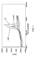
- FIG. 1 The results are in FIG. 1 shown.
- the comparison of the different electrode materials shows a very clear dependence of the reduction potential. It can be observed here that the reduction potential when using N-CNTs (-277 mV vs. Ag / AgNO 3 ) according to the invention is significantly less negative than for CNT-based electrodes (-309 mV vs. Ag / AgNO 3 ), however more negative than for a Pt electrode (-228 mV vs. Ag / AgNO 3 ).
Landscapes
- Engineering & Computer Science (AREA)
- Power Engineering (AREA)
- Chemical & Material Sciences (AREA)
- Microelectronics & Electronic Packaging (AREA)
- Nanotechnology (AREA)
- Chemical Kinetics & Catalysis (AREA)
- Electrochemistry (AREA)
- Physics & Mathematics (AREA)
- Mathematical Physics (AREA)
- Theoretical Computer Science (AREA)
- Crystallography & Structural Chemistry (AREA)
- Hybrid Cells (AREA)
Abstract
Eine farbstoffsensibilisierte Solarzelle umfasst eine Metalloxidelektrode, eine Gegenelektrode, welche der Metalloxidelektrode zugewandt ist und einen zwischen der Metalloxidelektrode und der Gegenelektrode angeordneten Elektrolyten, wobei die Metalloxidelektrode einen hierauf befindlichen Farbstoff umfasst und der Elektrolyt ein elektrochemisches Redoxpaar umfasst. Weiterhin sind zwischen der Metalloxidelektrode und der Gegenelektrode stickstoffdotierte Kohlenstoffnanoröhren (N-CNT) angeordnet, welche mit der Gegenelektrode elektrisch kontaktiert sind. Die Erfindung betrifft weiterhin ein Verfahren zur Gewinnung von elektrischer Energie mittels erfindungsgemäßer farbstoffsensibilisierter Solarzellen und die Verwendung von stickstoffdotierten Kohlenstoffnanoröhren als Katalysator in der Reaktion eines elektrochemischen Redoxpaares, insbesondere des Redoxpaares I-/I3 -.
Description
- Die vorliegende Erfindung betrifft eine farbstoffsensibilisierte Solarzelle, umfassend eine Metalloxidelektrode, eine Gegenelektrode, welche der Metalloxidelektrode zugewandt ist und einen zwischen der Metalloxidelektrode und der Gegenelektrode angeordneten Elektrolyten, wobei die Metalloxidelektrode einen hierauf befindlichen Farbstoff umfasst und der Elektrolyt ein elektrochemisches Redoxpaar umfasst. Die Erfindung betrifft weiterhin ein Verfahren zur Gewinnung von elektrischer Energie mittels erfindungsgemäßer farbstoffsensibilisierter Solarzellen und die Verwendung von stickstoffdotierten Kohlenstoffnanoröhren als Katalysator in der Reaktion eines elektrochemischen Redoxpaares.
- Eine farbstoffsensibilisierte Solarzelle oder Grätzel-Zelle ("dye-sensitized solar cell" oder "dye-sensitized nanocrystalline solar cell") ist im Wesentlichen aus zwei Elektroden aufgebaut, zwischen welchen ein photoelektrochemischer Prozess zur Gewinnung von Elektrizität abläuft. Ein wichtiger Bestandteil dieser Solarzelle ist die Gegenelektrode, an welcher ein Redoxpaar (I-/I3 -) zur Erhaltung des Prozesses reduziert wird. Darüber hinaus sollte diese Gegenelektrode einen effizienten Katalysator für diese Redoxreaktion beinhalten. Üblicherweise ist dieser ein edelmetall-basierte Katalysator wie zum Beispiel ein metallischer Platin-Katalysator. Der Einsatz von Edelmetallen ist jedoch immer mit hohen Kosten verbunden, so dass Alternativen hierzu gewünscht sind.
-
EP 2 061 049 A2 erwähnt in einer Ausführungsform der dort beschriebenen farbstoffsensibilisierten Solarzelle, dass deren zweite Elektrode ein leitfähiges Substrat umfasst, welches mit einer Platinschicht und/oder mit einer Schicht aus Kohlenstoffnanoröhren beschichtet ist. Die farbstoffsensibilisierte Solarzelle selbst umfasst eine erste Elektrode und eine der ersten Elektrode zugewandte zweite Elektrode mit einer zwischen der ersten und der zweiten Elektrode befindlichen Elektrolytschicht. Die erste Elektrode beinhaltet eine transparente und poröse leitende Schicht und eine Schicht von Halbleiteroxid-Nanopartikeln in den Poren der transparenten porösen leitenden Schicht, welche der zweiten Elektrode zugewandt ist. Farbstoffmoleküle sind in die Nanopartikel-Halbleiteroxidschicht adsorbiert. - Hinweise auf die Funktion oder Vorteile der Schicht aus Kohlenstoffnanoröhren werden in
EP 2 061 049 A2 jedoch nicht gegeben. -
EP 2 256 764 A2 offenbart eine farbstoffsensibilisierte Solarzelle mit einem Elektrolyten frei von organischen Lösungsmitteln, welche zu sehr effizienter photoelektrischer Umwandlung in der Lage ist. Weiterhin offenbart diese Patentanmeldung einen neuen und praktischen Elektrolyten frei von organischen Lösungsmitteln für eine solche farbstoffsensibilisierte Solarzelle. Ein Elektrolyt, der frei von organischen Lösungsmitteln ist, enthält ein leitfähiges Kohlenstoffmaterial, Wasser und eine anorganische Iodverbindung. Dieser Elektrolyt ist vorzugsweise ein quasi-fester Elektrolyt und das leitfähige Kohlenstoffmaterial im Elektrolyten weist vorzugsweise eine Oberfläche von 30 bis 300 m2/g auf. Gemäß dieser Patentanmeldung kann dann auf die Verwendung von Platin bei der Gegenelektrode verzichtet werden. In den Beispielen dieser Patentanmeldung wird eine Handelsform von Leitruß als Kohlenstoffmaterial eingesetzt. Der höchste angegebene photochemische Wirkungsgrad ist 1,82%. - Angesichts dieser Nachteile im Stand der Technik hat sich die vorliegende Erfindung die Aufgabe gestellt, eine Möglichkeit zur Verringerung oder Vermeidung des Einsatzes von teuren Edelmetallkatalysatoren in farbstoffsensibilisierten Solarzellen bereitzustellen, welche einen höheren Wirkungsgrad als bislang beschrieben aufweist.
- Diese Aufgabe wird erfindungsgemäß gelöst durch eine farbstoffsensibilisierte Solarzelle, umfassend:
- eine Metalloxidelektrode;
- eine Gegenelektrode, welche der Metalloxidelektrode zugewandt ist; und
- einen zwischen der Metalloxidelektrode und der Gegenelektrode angeordneten Elektrolyten;
- Es wurde festgestellt, dass stickstoffdotierte Kohlenstoffnanoröhren die Reaktion des in der Solarzelle befindlichen elektrochemischen Redoxpaares, insbesondere des Redoxpaares Iodid/Triiodid katalysieren können und damit eine hohe Effizienz auch ohne ein Edelmetall als Katalysator erreicht werden kann.
- Stickstoffdotierte Kohlenstoffnanoröhren (N-CNTs) sind im Rahmen der vorliegenden Erfindung Stickstoffatome umfassende Kohlenstoffnanoröhren (CNTs) und hierbei insbesondere solche, in deren Graphenlagen zusätzliche Stickstoffatome eingebaut sind. Weiterhin ist es beispielsweise möglich, dass stickstoffdotierte CNTs primäre, sekundäre, tertiäre und/oder quaternäre Aminogruppen aufweisen, welche direkt oder über weitere Molekülfragmente ("Spacer") an die CNTs gebunden sind. Die Bindungszustände lassen sich mittels Röntgen-Photoelektronenspektroskopie für die N1 s-Linie erkennen. So erhält man bei einer Anregung mit monochromatischer A1 Kα-Strahlung (1486,6 eV) Bindungsenergien zwischen 398 und 405 eV: beispielsweise für pyridinisch gebundenen Stickstoff eine Bindungsenergie von 398,7 +/- 0,2 eV, für pyrrolisch gebundenen Stickstoff eine Bindungsenergie von 400,7 eV, für quaternär gebundenen Stickstoff eine Bindungsenergie von 401,9 eV. Die oxidierten Stickstoffgruppen sind in der N 1 s-Linie bei 403 bis 405 eV sichtbar.
- Die stickstoffdotierten CNTs können in agglomerierter Form, in teilweise agglomerierter Form oder in desagglomerierter Form vorliegen.
- Es sind einige Verfahren zur Herstellung von N-CNTs bekannt. Geeignete Kohlenstoffnanoröhren als Ausgangsmaterial sind insbesondere alle einwandigen oder mehrwandigen Kohlenstoffnanoröhren vom Zylinder-Typ (zum Beispiel gemäß
US 5,747,161 undWO 86/03455 A1 EP 0 198 558 A2 undUS 7,018,601 ), oder mit zwiebelartiger Struktur. Bevorzugt sind mehrwandige Kohlenstoffnanoröhren vom Zylinder-Typ, Scroll-Typ, Multiscroll-Typ und Cup-stacked-Typ oder deren Mischungen einzusetzen. Günstig ist es, wenn die Kohlenstoffnanoröhren ein Verhältnis von Länge zu Außendurchmesser von ≥ 5, bevorzugt ≥100 haben. Besonders bevorzugt sind als Kohlenstoffnanoröhren mehrwandige Kohlenstoffnanoröhren mit einem durchschnittlichen äußeren Durchmesser von ≥ 3 nm bis ≤ 100 nm und einem Verhältnis von Länge zu Durchmesser von ≥ 5. -
WO 2010/127767 A1 offenbart ein Verfahren zur Herstellung von graphitischen Kohlenstoffmaterialien, die pyridinische, pyrrolische und/oder quaternäre Stickstoffgruppen mindestens an ihrer Oberfläche umfassen, ausgehend von Kohlenstoffnanoröhren, wobei die Kohlenstoffnanoröhren unter Stickstoffatmosphäre gemahlen werden. -
DE 10 2007 062 421 A1 beschreibt ein Verfahren zur Herstellung stickstoffdotierter Kohlenstoffnanoröhrchen (NCNT), welches mindestens die Schritte umfasst: - a. Fällen von mindestens einem Metall (M) aus einer Lösung eines Metallsalzes (MS) des mindestens einen Metalls (M) in einem Lösungsmittel (L), erhaltend eine Suspension (S) umfassend einen Feststoff (F),
- b. Abtrennen und gegebenenfalls Nachbehandeln des Feststoffes(F) aus der Suspension (S), erhaltend einen heterogenen Metallkatalysator (K),
- c. Einleiten des heterogenen Metallkatalysators (K) in eine Wirbelschicht,
- d. Reaktion mindestens eines Eduktes (E), das Kohlenstoff und Stickstoff umfasst, oder von mindestens zwei Edukten (E), wobei mindestens eines Kohlenstoff umfasst und mindestens eines Stickstoff umfasst, in der Wirbelschicht an dem heterogenen Metallkatalysator (K), erhaltend stickstoffdotierte Kohlenstoffnanoröhren (N-CNT),
- e. Austrag der stickstoffdotierten Kohlenstoffnanoröhren (N-CNT) aus der Wirbelschicht.
- Beispiele für geeignete Metalloxidelektroden sind Elektroden aus Titandioxid, SnO2 und/oder InO3. Der Farbstoff kann direkt auf der Metalloxidelektrode angebunden oder aufgetragen sein. Es ist aber auch möglich, dass zwischen der Metalloxidelektrode und dem Farbstoff sich noch eine oder mehrere geeignete Zwischenschichten befinden. Die Metalloxidelektrode kann ganz oder teilweise in Partikel-oder Nanopartikelform vorliegen. Beispiele für Substrate, auf welchen die Metalloxidelektrode angeordnet sein kann, sind Indium-Zink-Oxid (IZO), Indium-Zinn-Oxid (ITO) und/oder FTO, welches durch Dotierung von SnO2 mit Fluor erhalten wird.
- Die Gegenelektrode kann im einfachsten Fall ein elektrisch leitfähiges Material sein, auf welchem die stickstoffdotierten CNTs geträgert sind.
- Der Elektrolyt kann ein wässriger oder nicht-wässriger Elektrolyt sein. Weiterhin ist es möglich, dass der Elektrolyt eine ionische Flüssigkeit umfasst.
- Hinsichtlich des Farbstoffs sind zunächst keine Beschränkungen vorgesehen. So kann der Farbstoff ein Ru-basierter Metallkomplex und/oder einen organischen Farbstoff, insbesondere einen Farbstoff auswählt aus der Gruppe bestehend aus Azofarbstoffen, Oligoenen, Merocyaninen oder Mischungen von diesen sein.
- Das elektrochemische Redoxpaar ist ein reversibles Redoxpaar, dessen Redoxreaktion durch die stickstoffdotierten CNTs katalysiert wird. Nach einer Lichtabsorption durch den Farbstoff wird dieser angeregt und gibt unter Bildung einer oxidierten Form Elektronen in die (halbleitende) Metalloxidelektrode ab. Nach Durchlaufen eines elektrischen Stromkreises gelangen sie zur Gegenelektrode, wo sie, katalysiert durch die stickstoffdotierten CNTs, die oxidierte Form des Redoxpaares reduzieren. Die reduzierte Form des Redoxpaares steht dann zur Verfügung, um Elektronen direkt oder indirekt an die oxidierte Form des Farbstoffs abzugeben.
- Die vorliegende Erfindung wird nachfolgend im Zusammenhang mit bevorzugten Ausführungsformen weiter beschrieben. Sie können beliebig kombiniert werden, sofern sich aus dem Zusammenhang nicht eindeutig das Gegenteil ergibt.
- In einer Ausführungsform der erfindungsgemäßen Solarzelle umfasst das elektrochemische Redoxpaar eine anorganische Iodverbindung. Vorzugsweise ist das elektrochemische Redoxpaar das Redoxpaar I-/I3 -. Solche Redoxpaare lassen sich beispielsweise durch die Zugabe von Iodid, elementarem Iod, Iodat und/oder Periodat zum Elektrolyten erhalten.
- In einer weiteren Ausführungsform der erfindungsgemäßen Solarzelle ist die Gegenelektrode frei von Metallen aus der Gruppe Cobalt, Rhodium, Iridium, Nickel, Palladium, Platin, Kupfer, Silber und Gold. Der Begriff "frei von" beinhaltet im Rahmen der vorliegenden Erfindung die Anwesenheit von technisch unvermeidlichen Spuren der genannten Metalle, welche unter Umständen durch der Herstellung der CNTs mit eingeschleppt wurden. Auf jeden Fall beinhaltet die Gegenelektrode in dieser Ausführungsform keine makroskopischen Flächen dieser Metalle in elementarer Form, wie sie im Stand der Technik als zum Beispiel Platinelektroden anzutreffen sind.
- In einer weiteren Ausführungsform der erfindungsgemäßen Solarzelle sind die stickstoffdotierten Kohlenstoffnanoröhren mit der Gegenelektrode verbunden. Die Verbindung kann beispielsweise mechanisch oder mittels eines Bindemittels erfolgen. Vorzugsweise sind die stickstoffdotierten CNTs dann nicht mehr frei im Elektrolyten zwischen den beiden Elektroden angeordnet, sondern befinden sich nur noch an und im elektrischen Kontakt mit der Gegenelektrode.
- In einer weiteren Ausführungsform der erfindungsgemäßen Solarzelle weisen die stickstoffdotierten Kohlenstoffnanoröhren einen Stickstoffgehalt von ≥ 0,1 Atom-% bis ≤ 10 Atom-% auf. Der Atomgehalt lässt sich mittels Röntgen-Photoelektronenspektroskopie durch Integration der Signale für die N1s-Linie erkennen. Eine geeignete Anregung ist mit monochromatischer A1 Kα-Strahlung (1486,6 eV). Bevorzugte Bereiche für den Stickstoffgehalt sind ≥ 1 Atom-% bis ≤ 8 Atom-% und > 3 Atom-% bis ≤ 7 Atom-%. Weiterhin ist es bevorzugt, wenn ≥ 50% bis ≤ 100% der Stickstoffatome in pyridinischer und/oder pyrrolischer Form vorliegen.
- In einer weiteren Ausführungsform der erfindungsgemäßen Solarzelle umfassen die stickstoffdotierten Kohlenstoffnanoröhren pyridinische, pyrrolische und/oder quaternäre Stickstoffgruppen mindestens an ihrer Oberfläche. Wie bereits erwähnt lassen sich diese Gruppen durch ihre charakteristischen Signale für die N1s-Linie im Röntgen-Photoelektronenspektrum bei einer Anregung mit monochromatischer A1 Kα-Strahlung (1486,6 eV) durch Bindungsenergien zwischen 398 und 405 eV erkennen.
- In einer weiteren Ausführungsform der erfindungsgemäßen Solarzelle sind die stickstoffdotierten Kohlenstoffnanoröhren durch ein Verfahren erhältlich, welches die folgenden Schritte umfasst:
- Fällen zweier Metallsalze (MS) der Metalle (M) Cobalt und Mangan, zusammen mit weiteren Komponenten (I) umfassend Magnesium und Aluminium in einem Lösungsmittel (L) unter Erhalt einer Suspension (S) umfassend einen Feststoff (F);
- Abtrennen und gegebenenfalls Nachbehandeln des Feststoffs (F) aus der Suspension (S) unter Erhalt eines heterogenen Metallkatalysators (K) der Form M1:M2:I1O:I2O, in dem
M1 Mangan ist und in einem Massenanteil von ≥ 2% bis ≤ 65% vorliegt,
M2 Cobalt ist und in einem Massenanteil von ≥ 2% bis ≤ 80% vorliegt,
I1O Al2O3 ist und in einem Massenanteil von ≥ 5% bis ≤ 76% vorliegt und
I2O MgO ist und in einem Massenanteil von ≥ 5% bis ≤ 70% vorliegt,
wobei sich die genannten Massenanteile zu ≤ 100% addieren; - Einleiten des heterogenen Metallkatalysators (K) in eine Wirbelschicht;
- Reaktion mindestens eines gasförmigen Eduktes (E), das eine stickstoffhaltige organische Verbindung umfasst, in der Wirbelschicht an dem heterogenen Metallkatalysator (K) bei Temperaturen zwischen 300 °C und 1600 °C unter Erhalt von stickstoffdotierten Kohlenstoffnanoröhren;
- Austragen der stickstoffdotierten Kohlenstoffnanoröhren aus der Wirbelschicht.
- Vorzugsweise ist das Edukt (E), ausgewählt aus der Liste Acetonitril, Dimethylformamid, Acrylnitril, Propionsäurenitril, Buttersäurenitril, Pyridin, Pyrrol, Pyrazol, Pyrrolidin und/oder Piperidin.
- Es ist weiterhin möglich, neben dem mindestens einen Edukt (E) ein weiteres Edukt zu verwenden, das keinen Stickstoff umfasst. Bevorzugt ist dieses weitere Edukt ausgewählt ist aus der Liste Methan, Ethan, Propan, Butan, oder/oder höhere Aliphaten, die unter den Bedingungen in der Reaktionszone gasförmig vorliegen, sowie Ethylen, Propylen, Buten, Butadien und/oder höhere Olefine, die unter den Bedingungen in der Reaktionszone gasförmig vorliegen, Acetylen, oder aromatische Kohlenwasserstoffe, die unter den Bedingungen in der Reaktionszone gasförmig vorliegen. Weitere Gase umfassen bevorzugt Wasserstoff und/oder Inertgase. Inertgase umfassen bevorzugt Edelgase oder Stickstoff.
- Die Zusammensetzung des Gemisches der in die Reaktionszone eingeleiteten Gase besteht üblicherweise aus 0-90 Vol.-% Wasserstoff, 0-90 Vol.-% eines Inertgases wie z. B. Stickstoff oder Argon und 5-100 Vol.-% des mindestens (E) in gasförmigem Aggregatzustand, bevorzugt 0-50 Vol.-% Wasserstoff, 0-80 Vol.-% eines Inertgases wie z. B. Stickstoff oder Argon und 10-100 Vol.-% des Eduktes (E) in gasförmigem Aggregatzustand, besonders bevorzugt 0-40 Vol.-% Wasserstoff, 0-50 Vol.-% eines Inertgases wie z. B. Stickstoff oder Argon und 20-100 Vol.-% des Eduktes (E) in gasförmigem Aggregatzustand.
- In einer weiteren Ausführungsform der erfindungsgemäßen Solarzelle sind die stickstoffdotierten Kohlenstoffnanoröhren durch ein Verfahren erhältlich, welches das Mahlen von Kohlenstoffnanoröhren unter Ammoniak-, Amin- und/oder Stickstoffatmosphäre umfasst. Als Amine kommen grundsätzlich primäre, sekundäre und tertiäre Amine in Betracht. Eine bevorzugte Variante hierbei beinhaltet das Mahlen der CNTs unter einer unter Stickstoffatmosphäre mit einem Anteil an Stickstoff von mindestens 90 Vol.-% in einer Planetenmühle für einen Zeitraum von vier bis acht Stunden unter Eintrag einer Energie von 500 kJ pro Gramm CNTs bis 2500 kJ pro Gramm CNTs.
- In einer weiteren Ausführungsform der erfindungsgemäßen Solarzelle ist der Farbstoff ausgewählt aus der Gruppe umfassend Xanthenfarbstoffe wie Eosin-Y, Cumarinfarbstoffe, Triphenylmethanfarbstoffe, Cyananinfarbstoffe, Merocyaninfarbstoffe, Phthalocyaninfarbstoffe, Naphthalocyaninfarbstoffe, Porphyrinfarbstoffe, Polypyridin-Metallkomplexfarbstoffe, Ruthenium-Bipyridinfarbstoffe, Azofarbstoffe, Chinonfarbstoffe, Chinoniminfarbstoffe, Chinacridonfarbstoffe, Squariumfarbstoffe, Perylenfarbstoffe, Indigofarbstoffe, Polymethinfarbstoffe und/oder Riboflavinfarbstoffe.
- Ein weiterer Gegenstand der vorliegenden Erfindung ist ein Verfahren zur Gewinnung von elektrischer Energie mittels farbstoffsensibilisierter Solarzellen, wobei die Solarzelle eine erfindungsgemäße Solarzelle ist.
- Die vorliegende Erfindung betrifft weiterhin die Verwendung von stickstoffdotierten Kohlenstoffnanoröhren als Katalysator in der Reaktion eines elektrochemischen Redoxpaares, wobei das elektrochemische Redoxpaar eine anorganische Iodverbindung umfasst. Insbesondere ist das elektrochemische Redoxpaar das Redoxpaar I-/I3 -.
- Ohne hierauf beschränkt zu sein, wird die Erfindung anhand des nachfolgenden Beispiels weiter erläutert.
- Das Reduktionspotential des Redoxpaares I-/I3 - ist ein entscheidender Einflussfaktor für die Effizienz der farbstoffsensibilisierten Solarzelle. Je positiver das Reduktionspotential ist, desto höher ist die Effizienz der Solarzelle, da die Potentialdifferenz zwischen der Gegenelektrode und dem Fermi-Niveau des Halbleiters über die Leerlaufspannung (VOC ― open circuit voltage) entscheidet.
- Die Reduktion I-/I3 - ist ein komplexer chemischer Prozess, welcher den Einsatz von Katalysatoren für eine wirksame Solarzelle notwendig macht. Um das Potential von N-CNTs als Katalysator einschätzen zu können, wurden vergleichend die Reduktionspotentiale von I-/I3 - in Acetonitril durch Voltammetrie mit verschiedenen Elektroden bestimmt.
- Die benutzten N-CNTs wurden durch Elektronenspektroskopie (ESCA) charakterisiert und enthielten 6,5 Atom-% Stickstoff. Von diesen 6,5 Atom-% Stickstoff lagen 75% in pyridinischer beziehungsweise pyrolischer Form und 25% in nicht-aromatischer Form vor.
- Die Ergebnisse sind in
FIG. 1 dargestellt. Beim Vergleich der verschiedenen Elektrodenmaterialien zeigt sich eine sehr deutliche Abhängigkeit des Reduktionspotentials. Dabei ist zu beobachten, dass das Reduktionspotential bei der Verwendung von N-CNTs (-277 mV vs. Ag/AgNO3) erfindungsgemäß deutlich weniger negativ ist als bei CNT-basierten Elektroden (-309 mV vs. Ag/AgNO3) jedoch noch negativer als bei einer Pt-Elektrode (-228 mV vs. Ag/AgNO3).
Claims (13)
- Farbstoffsensibilisierte Solarzelle, umfassend:- eine Metalloxidelektrode;- eine Gegenelektrode, welche der Metalloxidelektrode zugewandt ist; und- einen zwischen der Metalloxidelektrode und der Gegenelektrode angeordneten Elektrolyten; wobei die Metalloxidelektrode einen hierauf befindlichen Farbstoff umfasst und der Elektrolyt ein elektrochemisches Redoxpaar umfasst,
dadurch gekennzeichnet, dass
zwischen der Metalloxidelektrode und der Gegenelektrode stickstoffdotierte Kohlenstoffnanoröhren angeordnet sind, welche mit der Gegenelektrode elektrisch kontaktiert sind. - Solarzelle gemäß Anspruch 1, wobei das elektrochemische Redoxpaar eine anorganische Iodverbindung umfasst.
- Solarzelle gemäß Anspruch 2, wobei das elektrochemische Redoxpaar das Redoxpaar I-/I3 - ist.
- Solarzelle gemäß Anspruch einem der Ansprüche 1 bis 3, wobei die Gegenelektrode frei von Metallen aus der Gruppe Cobalt, Rhodium, Iridium, Nickel, Palladium, Platin, Kupfer, Silber und Gold ist.
- Solarzelle gemäß einem der Ansprüche 1 bis 4, wobei die stickstoffdotierten Kohlenstoffnanoröhren mit der Gegenelektrode verbunden sind.
- Solarzelle gemäß einem der Ansprüche 1 bis 5, wobei die stickstoffdotierten Kohlenstoffnanoröhren einen Stickstoffgehalt von ≥ 0,1 Atom-% bis ≤ 10 Atom-% aufweisen.
- Solarzelle gemäß einem der Ansprüche 1 bis 6, wobei die stickstoffdotierten Kohlenstoffnanoröhren pyridinische, pyrrolische und/oder quaternäre Stickstoffgruppen mindestens an ihrer Oberfläche umfassen.
- Solarzelle gemäß einem der Ansprüche 1 bis 7, wobei die stickstoffdotierten Kohlenstoffnanoröhren durch ein Verfahren erhältlich sind, welches die folgenden Schritte umfasst:- Fällen zweier Metallsalze (MS) der Metalle (M) Cobalt und Mangan, zusammen mit weiteren Komponenten (I) umfassend Magnesium und Aluminium in einem Lösungsmittel (L) unter Erhalt einer Suspension (S) umfassend einen Feststoff (F);- Abtrennen und gegebenenfalls Nachbehandeln des Feststoffs (F) aus der Suspension (S) unter Erhalt eines heterogenen Metallkatalysators (K) der Form M1:M2:I1O:I2O, in dem
M1 Mangan ist und in einem Massenanteil von ≥ 2% bis ≤ 65% vorliegt,
M2 Cobalt ist und in einem Massenanteil von ≥ 2% bis ≤ 80% vorliegt,
I1O Al2O3 ist und in einem Massenanteil von ≥ 5% bis ≤ 76% vorliegt und
I2O MgO ist und in einem Massenanteil von ≥ 5% bis ≤ 70% vorliegt,
wobei sich die genannten Massenanteile zu ≤ 100% addieren;- Einleiten des heterogenen Metallkatalysators (K) in eine Wirbelschicht;- Reaktion mindestens eines gasförmigen Eduktes (E), das eine stickstoffhaltige organische Verbindung umfasst, in der Wirbelschicht an dem heterogenen Metallkatalysator (K) bei Temperaturen zwischen 300 °C und 1600 °C unter Erhalt von stickstoffdotierten Kohlenstoffnanoröhren;- Austragen der stickstoffdotierten Kohlenstoffnanoröhren aus der Wirbelschicht. - Solarzelle gemäß einem der Ansprüche 1 bis 7, wobei die stickstoffdotierten Kohlenstoffnanoröhren durch ein Verfahren erhältlich sind, welches das Mahlen von Kohlenstoffnanoröhren unter Ammoniak-, Amin- und/oder Stickstoffatmosphäre umfasst.
- Solarzelle gemäß einem der Ansprüche 1 bis 9, wobei der Farbstoff ausgewählt ist aus der Gruppe umfassend Xanthenfarbstoffe wie Eosin-Y, Cumarinfarbstoffe, Triphenylmethanfarbstoffe, Cyananinfarbstoffe, Merocyaninfarbstoffe, Phthalocyaninfarbstoffe, Naphthalocyaninfarbstoffe, Porphyrinfarbstoffe, Polypyridin-Metallkomplexfarbstoffe, Ruthenium-Bipyridinfarbstoffe, Azofarbstoffe, Chinonfarbstoffe, Chinoniminfarbstoffe, Chinacridonfarbstoffe, Squariumfarbstoffe, Perylenfarbstoffe, Indigofarbstoffe, Polymethinfarbstoffe und/oder Riboflavinfarbstoffe.
- Verfahren zur Gewinnung von elektrischer Energie mittels farbstoffsensibilisierter Solarzellen, dadurch gekennzeichnet, dass die Solarzelle eine Solarzelle gemäß einem der Ansprüche 1 bis 10 ist.
- Verwendung von stickstoffdotierten Kohlenstoffnanoröhren als Katalysator in der Reaktion eines elektrochemischen Redoxpaares, dadurch gekennzeichnet, dass das elektrochemische Redoxpaar eine anorganische Iodverbindung umfasst.
- Verwendung gemäß Anspruch 12, wobei das elektrochemische Redoxpaar das Redoxpaar I-/I3 - ist.
Priority Applications (9)
| Application Number | Priority Date | Filing Date | Title |
|---|---|---|---|
| EP11160619A EP2506276A1 (de) | 2011-03-31 | 2011-03-31 | Farbstoffsensibilisierte Solarzelle mit stickstoffdotierten Kohlenstoffnanoröhren |
| MX2013011221A MX2013011221A (es) | 2011-03-31 | 2012-03-26 | Celula solar sensibilizada por colorante con nanotubos de carbono dopado con nitrogeno. |
| US14/008,120 US20140014174A1 (en) | 2011-03-31 | 2012-03-26 | Dye-sensitized solar cell with nitrogen-doped carbon nanotubes |
| BR112013025104-2A BR112013025104A2 (pt) | 2011-03-31 | 2012-03-26 | células solares sensibilizadas por corante com nanotubos de carbono dopados com nitrogênio |
| KR1020137025197A KR20140014187A (ko) | 2011-03-31 | 2012-03-26 | 질소-도핑된 탄소 나노튜브를 포함하는 염료-감응 태양 전지 |
| AU2012234396A AU2012234396A1 (en) | 2011-03-31 | 2012-03-26 | Dye-sensitized solar cell with nitrogen-doped carbon nanotubes |
| EP12711627.5A EP2691966B1 (de) | 2011-03-31 | 2012-03-26 | Farbstoffsensibilisierte solarzelle mit stickstoffdotierten kohlenstoffnanoröhren |
| PCT/EP2012/055327 WO2012130801A1 (de) | 2011-03-31 | 2012-03-26 | Farbstoffsensibilisierte solarzelle mit stickstoffdotierten kohlenstoffnanoröhren |
| CN201280017162.5A CN103503098A (zh) | 2011-03-31 | 2012-03-26 | 具有氮掺杂碳纳米管的染料敏化太阳能电池 |
Applications Claiming Priority (1)
| Application Number | Priority Date | Filing Date | Title |
|---|---|---|---|
| EP11160619A EP2506276A1 (de) | 2011-03-31 | 2011-03-31 | Farbstoffsensibilisierte Solarzelle mit stickstoffdotierten Kohlenstoffnanoröhren |
Publications (1)
| Publication Number | Publication Date |
|---|---|
| EP2506276A1 true EP2506276A1 (de) | 2012-10-03 |
Family
ID=44168323
Family Applications (2)
| Application Number | Title | Priority Date | Filing Date |
|---|---|---|---|
| EP11160619A Withdrawn EP2506276A1 (de) | 2011-03-31 | 2011-03-31 | Farbstoffsensibilisierte Solarzelle mit stickstoffdotierten Kohlenstoffnanoröhren |
| EP12711627.5A Not-in-force EP2691966B1 (de) | 2011-03-31 | 2012-03-26 | Farbstoffsensibilisierte solarzelle mit stickstoffdotierten kohlenstoffnanoröhren |
Family Applications After (1)
| Application Number | Title | Priority Date | Filing Date |
|---|---|---|---|
| EP12711627.5A Not-in-force EP2691966B1 (de) | 2011-03-31 | 2012-03-26 | Farbstoffsensibilisierte solarzelle mit stickstoffdotierten kohlenstoffnanoröhren |
Country Status (8)
| Country | Link |
|---|---|
| US (1) | US20140014174A1 (de) |
| EP (2) | EP2506276A1 (de) |
| KR (1) | KR20140014187A (de) |
| CN (1) | CN103503098A (de) |
| AU (1) | AU2012234396A1 (de) |
| BR (1) | BR112013025104A2 (de) |
| MX (1) | MX2013011221A (de) |
| WO (1) | WO2012130801A1 (de) |
Families Citing this family (2)
| Publication number | Priority date | Publication date | Assignee | Title |
|---|---|---|---|---|
| CN104624190B (zh) * | 2013-11-12 | 2017-04-26 | 华中科技大学 | 一种钴基过渡金属氧还原催化剂及其制备方法和应用 |
| CN113003566B (zh) * | 2021-03-16 | 2022-11-01 | 山西医科大学 | 镍颗粒修饰碳基质、制备和代谢小分子的质谱分析应用 |
Citations (10)
| Publication number | Priority date | Publication date | Assignee | Title |
|---|---|---|---|---|
| WO1986003455A1 (en) | 1984-12-06 | 1986-06-19 | Hyperion Catalysis International, Inc. | Carbon fibrils, method for producing same, and compositions containing same |
| EP0198558A2 (de) | 1985-04-15 | 1986-10-22 | The Dow Chemical Company | Verfahren zur Herstellung von Kohlenstoffilamenten und durch dieses Verfahren erhaltene Kohlenstoffilamente |
| US5747161A (en) | 1991-10-31 | 1998-05-05 | Nec Corporation | Graphite filaments having tubular structure and method of forming the same |
| WO2004000727A2 (fr) * | 2002-06-24 | 2003-12-31 | Commissariat A L'energie Atomique | Procede et dispositif de depot par pyrolyse de nanotubes de carbone ou de nanotubes de carbone dopes a l'azote |
| US7018601B2 (en) | 2001-03-21 | 2006-03-28 | Gsi Creos Corporation | Carbon fiber product, and method of adjusting length of carbon fiber product |
| EP1653549A1 (de) * | 2003-07-14 | 2006-05-03 | Fujikura Ltd. | Elektrolyt-zusammensetzung und fotoelektrischer wandler und farbstoffsensibilisierte solarzelle damit |
| EP2061049A2 (de) | 2007-11-19 | 2009-05-20 | Electronics and Telecommunications Research Institute | Farbstoffsensibilisierte Solarzelle mit anodenporöser Leitschicht |
| DE102007062421A1 (de) | 2007-12-20 | 2009-06-25 | Bayer Technology Services Gmbh | Verfahren zur Herstellung von Stickstoff-dotierten Kohlenstoffnanoröhrchen |
| WO2010127767A1 (de) | 2009-05-02 | 2010-11-11 | Bayer Technology Services Gmbh | Verfahren zur herstellung von kohlenstoffmaterialien mit stickstoffmodifikation ausgehend von kohlenstoffnanoröhrchen |
| EP2256764A2 (de) | 2009-05-28 | 2010-12-01 | TDK Corporation | Farbstoffsensibilisierte Solarzelle und organisches, lösungsmittelfreies Elektrolyt für farbstoffsensibilisierte Solarzelle |
-
2011
- 2011-03-31 EP EP11160619A patent/EP2506276A1/de not_active Withdrawn
-
2012
- 2012-03-26 MX MX2013011221A patent/MX2013011221A/es not_active Application Discontinuation
- 2012-03-26 EP EP12711627.5A patent/EP2691966B1/de not_active Not-in-force
- 2012-03-26 KR KR1020137025197A patent/KR20140014187A/ko not_active Withdrawn
- 2012-03-26 CN CN201280017162.5A patent/CN103503098A/zh active Pending
- 2012-03-26 WO PCT/EP2012/055327 patent/WO2012130801A1/de not_active Ceased
- 2012-03-26 US US14/008,120 patent/US20140014174A1/en not_active Abandoned
- 2012-03-26 BR BR112013025104-2A patent/BR112013025104A2/pt not_active IP Right Cessation
- 2012-03-26 AU AU2012234396A patent/AU2012234396A1/en not_active Abandoned
Patent Citations (10)
| Publication number | Priority date | Publication date | Assignee | Title |
|---|---|---|---|---|
| WO1986003455A1 (en) | 1984-12-06 | 1986-06-19 | Hyperion Catalysis International, Inc. | Carbon fibrils, method for producing same, and compositions containing same |
| EP0198558A2 (de) | 1985-04-15 | 1986-10-22 | The Dow Chemical Company | Verfahren zur Herstellung von Kohlenstoffilamenten und durch dieses Verfahren erhaltene Kohlenstoffilamente |
| US5747161A (en) | 1991-10-31 | 1998-05-05 | Nec Corporation | Graphite filaments having tubular structure and method of forming the same |
| US7018601B2 (en) | 2001-03-21 | 2006-03-28 | Gsi Creos Corporation | Carbon fiber product, and method of adjusting length of carbon fiber product |
| WO2004000727A2 (fr) * | 2002-06-24 | 2003-12-31 | Commissariat A L'energie Atomique | Procede et dispositif de depot par pyrolyse de nanotubes de carbone ou de nanotubes de carbone dopes a l'azote |
| EP1653549A1 (de) * | 2003-07-14 | 2006-05-03 | Fujikura Ltd. | Elektrolyt-zusammensetzung und fotoelektrischer wandler und farbstoffsensibilisierte solarzelle damit |
| EP2061049A2 (de) | 2007-11-19 | 2009-05-20 | Electronics and Telecommunications Research Institute | Farbstoffsensibilisierte Solarzelle mit anodenporöser Leitschicht |
| DE102007062421A1 (de) | 2007-12-20 | 2009-06-25 | Bayer Technology Services Gmbh | Verfahren zur Herstellung von Stickstoff-dotierten Kohlenstoffnanoröhrchen |
| WO2010127767A1 (de) | 2009-05-02 | 2010-11-11 | Bayer Technology Services Gmbh | Verfahren zur herstellung von kohlenstoffmaterialien mit stickstoffmodifikation ausgehend von kohlenstoffnanoröhrchen |
| EP2256764A2 (de) | 2009-05-28 | 2010-12-01 | TDK Corporation | Farbstoffsensibilisierte Solarzelle und organisches, lösungsmittelfreies Elektrolyt für farbstoffsensibilisierte Solarzelle |
Non-Patent Citations (1)
| Title |
|---|
| K. S. LEE, W. J. LEE, N.-G. PARK, S. O. KIM, J. H. PARK: "Transferred vertically aligne N-doped carbon nanotube arrays: use in dye-sensitized solar cells as counter electrode", CHEM. COMMUN., 4 March 2011 (2011-03-04), pages 4264 - 4266, XP002657760 * |
Also Published As
| Publication number | Publication date |
|---|---|
| WO2012130801A1 (de) | 2012-10-04 |
| KR20140014187A (ko) | 2014-02-05 |
| BR112013025104A2 (pt) | 2019-09-24 |
| EP2691966A1 (de) | 2014-02-05 |
| AU2012234396A1 (en) | 2013-10-03 |
| US20140014174A1 (en) | 2014-01-16 |
| MX2013011221A (es) | 2013-10-17 |
| EP2691966B1 (de) | 2018-08-01 |
| CN103503098A (zh) | 2014-01-08 |
Similar Documents
| Publication | Publication Date | Title |
|---|---|---|
| Yan et al. | Efficient photocatalytic H2 evolution using NiS/ZnIn2S4 heterostructures with enhanced charge separation and interfacial charge transfer | |
| Chandrasekaran et al. | Electrocatalytic performance of carbon dots/palladium nanoparticles composite towards hydrogen evolution reaction in acid medium | |
| Song et al. | Hydrothermal synthesis of iron pyrite (FeS2) as efficient counter electrodes for dye-sensitized solar cells | |
| Zhu et al. | Choose a reasonable counter electrode catalyst toward a fixed redox couple in dye-sensitized solar cells | |
| DE69929853T2 (de) | Metallkomplex nützlich als Sensibilisator, farbstoffsensibilisierte Oxidhalbleiterelektrode und damit ausgestattete Solarzelle | |
| US7338590B1 (en) | Water-splitting using photocatalytic porphyrin-nanotube composite devices | |
| CN102066243B (zh) | 钛氧化物包覆的碳纤维和多孔钛氧化物包覆的碳材料组合物 | |
| Sun et al. | Low-crystalline FeOOH nanoflower assembled mesoporous film anchored on MWCNTs for high-performance supercapacitor electrodes | |
| Lee et al. | Molybdenum disulfide quantum dots decorated bismuth sulfide as a superior noble-metal-free photocatalyst for hydrogen evolution through harnessing a broad solar spectrum | |
| Torres et al. | Performance and stability of counter electrodes based on reduced few-layer graphene oxide sheets and reduced graphene oxide quantum dots for dye-sensitized solar cells | |
| KR102061540B1 (ko) | 질소가 도핑된 나노 카본 소재 및 이의 제조 방법 | |
| EP2292560A1 (de) | Titanoxidstruktur und poröse titanoxidzusammensetzung | |
| Jaafar et al. | The use of carbon black-TiO2 composite prepared using solid state method as counter electrode and E. conferta as sensitizer for dye-sensitized solar cell (DSSC) applications | |
| Dissanayake et al. | A low-cost, vein graphite/tin oxide nanoparticles based composite counter electrode for efficient dye-sensitized solar cells | |
| Rogier et al. | MoO3–carbon nanotube negative electrode designed for a fully hybrid asymmetric metal oxide-based pseudocapacitor operating in an organic electrolyte | |
| Wang et al. | Highly dispersed redox-active polyoxometalates’ periodic deposition on multi-walled carbon nanotubes for boosting electrocatalytic triiodide reduction in dye-sensitized solar cells | |
| Guo et al. | Ultralong In2S3 nanotubes on graphene substrate with enhanced electrocatalytic activity | |
| Kamble et al. | Redox active MoO3-Polyaniline hybrid composite for hydrogen evolution reaction and supercapacitor application | |
| Arjun Kumar et al. | CdSe quantum dots bedecked on ZnO/TiO2/CuO ternary nanocomposite for enhanced photocatalytic and photovoltaic applications | |
| Wang et al. | Regulating the type of cobalt porphyrins for synergistic promotion of photoelectrochemical water splitting of BiVO4 | |
| Kuppu et al. | The surfactants mediated electropolymerized poly (aniline)(PANI)-reduced graphene oxide (rGO) composite counter electrode for dye-sensitized solar cell | |
| Kim et al. | Solution-processable rGO–Pt nanohybrids synthesized in an aqueous fructose solution for transparent and efficient dye-sensitized solar cells | |
| Wang et al. | Liquid-metal-induced hydrogen insertion in photoelectrodes for enhanced photoelectrochemical water oxidation | |
| Tounsi et al. | One-step electrochemical synthesis of FTO/MnO2-graphene composite for electrochemical energy storage | |
| Nongthombam et al. | Hydrothermal synthesis of rGO-TiO2 nanocomposites for electrochemical performance |
Legal Events
| Date | Code | Title | Description |
|---|---|---|---|
| PUAI | Public reference made under article 153(3) epc to a published international application that has entered the european phase |
Free format text: ORIGINAL CODE: 0009012 |
|
| AK | Designated contracting states |
Kind code of ref document: A1 Designated state(s): AL AT BE BG CH CY CZ DE DK EE ES FI FR GB GR HR HU IE IS IT LI LT LU LV MC MK MT NL NO PL PT RO RS SE SI SK SM TR |
|
| AX | Request for extension of the european patent |
Extension state: BA ME |
|
| RAP1 | Party data changed (applicant data changed or rights of an application transferred) |
Owner name: BAYER INTELLECTUAL PROPERTY GMBH |
|
| STAA | Information on the status of an ep patent application or granted ep patent |
Free format text: STATUS: THE APPLICATION IS DEEMED TO BE WITHDRAWN |
|
| 18D | Application deemed to be withdrawn |
Effective date: 20130404 |