EP2506112A2 - Air volume control device and air volume control method - Google Patents
Air volume control device and air volume control method Download PDFInfo
- Publication number
- EP2506112A2 EP2506112A2 EP12152261A EP12152261A EP2506112A2 EP 2506112 A2 EP2506112 A2 EP 2506112A2 EP 12152261 A EP12152261 A EP 12152261A EP 12152261 A EP12152261 A EP 12152261A EP 2506112 A2 EP2506112 A2 EP 2506112A2
- Authority
- EP
- European Patent Office
- Prior art keywords
- temperature
- volume control
- fan
- air volume
- revolutions
- Prior art date
- Legal status (The legal status is an assumption and is not a legal conclusion. Google has not performed a legal analysis and makes no representation as to the accuracy of the status listed.)
- Withdrawn
Links
Images

Classifications
-
- H—ELECTRICITY
- H05—ELECTRIC TECHNIQUES NOT OTHERWISE PROVIDED FOR
- H05K—PRINTED CIRCUITS; CASINGS OR CONSTRUCTIONAL DETAILS OF ELECTRIC APPARATUS; MANUFACTURE OF ASSEMBLAGES OF ELECTRICAL COMPONENTS
- H05K7/00—Constructional details common to different types of electric apparatus
- H05K7/20—Modifications to facilitate cooling, ventilating, or heating
- H05K7/20009—Modifications to facilitate cooling, ventilating, or heating using a gaseous coolant in electronic enclosures
- H05K7/20209—Thermal management, e.g. fan control
-
- F—MECHANICAL ENGINEERING; LIGHTING; HEATING; WEAPONS; BLASTING
- F24—HEATING; RANGES; VENTILATING
- F24F—AIR-CONDITIONING; AIR-HUMIDIFICATION; VENTILATION; USE OF AIR CURRENTS FOR SCREENING
- F24F11/00—Control or safety arrangements
- F24F11/62—Control or safety arrangements characterised by the type of control or by internal processing, e.g. using fuzzy logic, adaptive control or estimation of values
- F24F11/63—Electronic processing
-
- F—MECHANICAL ENGINEERING; LIGHTING; HEATING; WEAPONS; BLASTING
- F24—HEATING; RANGES; VENTILATING
- F24F—AIR-CONDITIONING; AIR-HUMIDIFICATION; VENTILATION; USE OF AIR CURRENTS FOR SCREENING
- F24F11/00—Control or safety arrangements
- F24F11/70—Control systems characterised by their outputs; Constructional details thereof
- F24F11/72—Control systems characterised by their outputs; Constructional details thereof for controlling the supply of treated air, e.g. its pressure
- F24F11/74—Control systems characterised by their outputs; Constructional details thereof for controlling the supply of treated air, e.g. its pressure for controlling air flow rate or air velocity
- F24F11/76—Control systems characterised by their outputs; Constructional details thereof for controlling the supply of treated air, e.g. its pressure for controlling air flow rate or air velocity by means responsive to temperature, e.g. bimetal springs
-
- F—MECHANICAL ENGINEERING; LIGHTING; HEATING; WEAPONS; BLASTING
- F24—HEATING; RANGES; VENTILATING
- F24F—AIR-CONDITIONING; AIR-HUMIDIFICATION; VENTILATION; USE OF AIR CURRENTS FOR SCREENING
- F24F11/00—Control or safety arrangements
- F24F11/70—Control systems characterised by their outputs; Constructional details thereof
- F24F11/72—Control systems characterised by their outputs; Constructional details thereof for controlling the supply of treated air, e.g. its pressure
- F24F11/74—Control systems characterised by their outputs; Constructional details thereof for controlling the supply of treated air, e.g. its pressure for controlling air flow rate or air velocity
- F24F11/77—Control systems characterised by their outputs; Constructional details thereof for controlling the supply of treated air, e.g. its pressure for controlling air flow rate or air velocity by controlling the speed of ventilators
-
- G—PHYSICS
- G06—COMPUTING OR CALCULATING; COUNTING
- G06F—ELECTRIC DIGITAL DATA PROCESSING
- G06F1/00—Details not covered by groups G06F3/00 - G06F13/00 and G06F21/00
- G06F1/16—Constructional details or arrangements
- G06F1/20—Cooling means
-
- G—PHYSICS
- G06—COMPUTING OR CALCULATING; COUNTING
- G06F—ELECTRIC DIGITAL DATA PROCESSING
- G06F1/00—Details not covered by groups G06F3/00 - G06F13/00 and G06F21/00
- G06F1/16—Constructional details or arrangements
- G06F1/20—Cooling means
- G06F1/206—Cooling means comprising thermal management
-
- H—ELECTRICITY
- H05—ELECTRIC TECHNIQUES NOT OTHERWISE PROVIDED FOR
- H05K—PRINTED CIRCUITS; CASINGS OR CONSTRUCTIONAL DETAILS OF ELECTRIC APPARATUS; MANUFACTURE OF ASSEMBLAGES OF ELECTRICAL COMPONENTS
- H05K7/00—Constructional details common to different types of electric apparatus
- H05K7/20—Modifications to facilitate cooling, ventilating, or heating
- H05K7/20709—Modifications to facilitate cooling, ventilating, or heating for server racks or cabinets; for data centers, e.g. 19-inch computer racks
- H05K7/20836—Thermal management, e.g. server temperature control
-
- F—MECHANICAL ENGINEERING; LIGHTING; HEATING; WEAPONS; BLASTING
- F24—HEATING; RANGES; VENTILATING
- F24F—AIR-CONDITIONING; AIR-HUMIDIFICATION; VENTILATION; USE OF AIR CURRENTS FOR SCREENING
- F24F11/00—Control or safety arrangements
- F24F11/30—Control or safety arrangements for purposes related to the operation of the system, e.g. for safety or monitoring
-
- F—MECHANICAL ENGINEERING; LIGHTING; HEATING; WEAPONS; BLASTING
- F24—HEATING; RANGES; VENTILATING
- F24F—AIR-CONDITIONING; AIR-HUMIDIFICATION; VENTILATION; USE OF AIR CURRENTS FOR SCREENING
- F24F2110/00—Control inputs relating to air properties
- F24F2110/10—Temperature
-
- H—ELECTRICITY
- H01—ELECTRIC ELEMENTS
- H01L—SEMICONDUCTOR DEVICES NOT COVERED BY CLASS H10
- H01L2924/00—Indexing scheme for arrangements or methods for connecting or disconnecting semiconductor or solid-state bodies as covered by H01L24/00
- H01L2924/0001—Technical content checked by a classifier
- H01L2924/0002—Not covered by any one of groups H01L24/00, H01L24/00 and H01L2224/00
-
- Y—GENERAL TAGGING OF NEW TECHNOLOGICAL DEVELOPMENTS; GENERAL TAGGING OF CROSS-SECTIONAL TECHNOLOGIES SPANNING OVER SEVERAL SECTIONS OF THE IPC; TECHNICAL SUBJECTS COVERED BY FORMER USPC CROSS-REFERENCE ART COLLECTIONS [XRACs] AND DIGESTS
- Y02—TECHNOLOGIES OR APPLICATIONS FOR MITIGATION OR ADAPTATION AGAINST CLIMATE CHANGE
- Y02B—CLIMATE CHANGE MITIGATION TECHNOLOGIES RELATED TO BUILDINGS, e.g. HOUSING, HOUSE APPLIANCES OR RELATED END-USER APPLICATIONS
- Y02B30/00—Energy efficient heating, ventilation or air conditioning [HVAC]
- Y02B30/70—Efficient control or regulation technologies, e.g. for control of refrigerant flow, motor or heating
Definitions
- the embodiments discussed herein are directed to an air volume control device, an air volume control method, and an air volume control program.
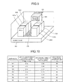
- FIG. 9 is a diagram illustrating an exemplary configuration of a data center.
- a data center 901 a plurality of racks 902a to 902f are installed in columns with front surfaces and rear surfaces thereof facing the same directions, respectively.
- a plurality of electronic devices such as servers are installed in each of the racks 902a to 902f.
- an amount of heat generation in an electronic component such as a CPU (central processing unit) has been continuously increasing. If a temperature of an electronic component as represented by a CPU becomes high, the electronic device may be operationally unstable. Therefore, in the data center, the electronic components are appropriately cooled so that the electronic devices can operate stably.
- cooling air of 20 to 25°C is blown out from an under floor 903 by an air-conditioning equipment 904, and is supplied to the racks 902a to 902f via floor surface apertured panels 905.
- the electronic devices mounted in the racks 902a to 902f rotate fans included therein to take in the cooling air from outside of housings of the electronic devices, thereby cooling the electronic components within the housings.
- An amount of heat generation in a CPU changes in accordance with an amount of processing load. Therefore in the data center, the electronic device changes the number of revolutions of the fan in accordance with the amount of heat generation in the CPU so as to change an amount of cooling air to be taken in from outside of the electronic device. For example, the number of revolutions of the fan is set in accordance with an intake air temperature of the electronic device or a CPU temperature.
- a sufficient amount of cooling air has been supplied to racks via floor surface apertured panels with respect to an amount of cooling air taken in inside the housings of the electronic devices by the electronic devices.
- the electronic devices take in inside the housings thereof the cooling air supplied to the racks via the floor surface apertured panels, thereby appropriately cooling the electronic components of the electronic devices.
- a rack in a data center mounts a blade server having an improved processing capability and a larger amount of heat generation as compared to a conventional server.
- an amount of air taken in by electronic devices becomes greater than cooling air supplied to the racks via the floor surface apertured panels.
- there occurs a hot spot phenomenon such that warm exhaust air exhausted by the electronic devices is taken in again by the electronic devices together with the cooling air supplied to the racks.
- exhaust air recirculation Such a situation that discharge from an electronic device is taken in again by the electronic device is called "exhaust air recirculation.”
- FIG. 10 is a diagram illustrating changes in an electronic component temperature when the number of fan revolutions is varied in a data center where racks having blade servers mounted therein are arranged.
- an amount of cooling air supplied to the racks via the floor surface apertured panels is sufficient for an amount of cooling air taken in by the electronic devices.
- an air volume of the electronic device increases, and the electronic component temperature is therefore decreased from 98°C to 71°C.
- an object in one aspect of an embodiment of the invention to provide an air volume control device, an air volume control method, and an air volume control program capable of preventing an increase in electronic component temperature.
- an air volume control device includes a determination unit that determines whether or not a cooling capacity of an electronic device fulfills a predetermined cooling capacity, a decreasing unit that decreases the number of revolutions of a fan for cooling the electronic device if the determination unit determines that the cooling capacity of the electronic device is failing to fulfill the predetermined cooling capacity.
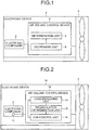
- FIG. 1 is a block diagram illustrating a configuration of an electronic device containing an air volume control device according to the first embodiment.
- an electronic device 1 has an electronic component 2, a fan 3, and an air volume control device 4.
- the electronic device 1 is a 1U server containing the electronic component 2 inside a housing of about 45 mm in height ⁇ about 19 inches in width ⁇ about 540 mm in depth, for example. Note that the numbers of electronic components and fans are merely illustrative in the first embodiment, and the numbers thereof are not limited thereto.
- Examples of the electronic component 2 include a CPU (central processing unit), a RAM (random access memory), and an HDD (hard disk drive).
- the electronic component 2 radiates heat generated from a surface of the electronic component 2 to air taken in inside the electronic device 1 by the fan 3 via a radiator such as a heat sink.
- a radiator such as a heat sink.
- the electronic component 2 is an example of a heating element.
- the fan 3 is an axial flow fan of a PWM (pulse width modulation) type or the like, for example.
- PWM pulse width modulation
- the fan 3 changes the number of revolutions thereof. For example, when a temperature of the electronic component 2 is increased, the fan 3 increases the number of revolutions thereof to increase the wind speed of the fan, thereby cooling the electronic component 2.
- the air volume control device 4 includes a determination unit 5 and the decreasing unit 6.
- the determination unit 5 determines whether or not the cooling capacity of the electronic device 1 fulfills a predetermined cooling capacity. For example, the determination unit 5 determines whether or not air exhausted from the electronic device 1 has been recirculated into air sucked in by the electronic device 1. If it is determined that recirculation has occurred, the determination unit 5 determines that the cooling capacity of the electronic device 1 is failing to fulfill the predetermined cooling capacity.
- the decreasing unit 6 decreases the number of revolutions of the fan 3 for cooling the electronic device 1.
- the determination unit 5 determines that the cooling capacity of the electronic device 1 is failing to fulfill the predetermined cooling capacity. If it is determined by the determination unit 5 that the cooling capacity of the electronic device 1 is failing to fulfill the predetermined cooling capacity, the decreasing unit 6 decreases the number of revolutions of the fan 3, thereby eliminating the recirculation. As a result, if it is determined that the cooling capacity of the electronic device 1 is failing to fulfill the predetermined cooling capacity, the air volume control device 4 according to the first embodiment can prevent an increase in temperature of the electronic component 2 by decreasing the number of revolutions of the fan 3 for cooling the electronic component 2.
- an air volume control device monitors a temperature of an electronic component and determines whether or not there is recirculation, thereby determining whether or not the cooling capacity of an electronic device fulfills a predetermined cooling capacity.
- the air volume control device according to the second embodiment performs feedback control such that the number of fan revolutions is increased in accordance with an increase in the temperature of the electronic component and the number of fan revolutions is decreased in accordance with a decrease in the temperature of the electronic component during normal times.
- the air volume control device determines whether or not there is recirculation at a period of time during which there is no change in load on the electronic component.
- the air volume control device performs control for restoring the number of fan revolutions to obtain a state where no recirculation occurs.
- a configuration of the electronic device containing the air volume control device according to the second embodiment, a processing procedure by the air volume control device according to the second embodiment, and an advantageous effect of the second embodiment will be described in order.
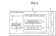
- FIG. 2 is a block diagram illustrating the configuration of the electronic device containing the air volume control device according to the second embodiment.
- An electronic device 10 according to the second embodiment includes the electronic component 2, the fan 3, a temperature detecting unit 11, and an air volume control device 12.
- the electronic device 10 is a 1U server containing the electronic component 2 and the like inside a housing of about 45 mm in height ⁇ about 19 inches in width ⁇ about 540 mm in depth, for example.
- functional units operating similarly to the units illustrated in FIG. 1 are denoted by the same reference numerals and the detailed descriptions thereof will be omitted.
- the numbers of electronic components, temperature detecting units, and fans are merely illustrative in the second embodiment, and the numbers thereof are not limited thereto.
- the temperature detecting unit 11 is a thermal diode inside an LSI, for example, and periodically measures the temperature of the electronic component 2 after the acceptance of an instruction for starting control from a user via an accepting unit not illustrated in the figure.
- the temperature of the electronic component 2 is hereinafter referred to as an electronic component temperature Tj .
- the temperature detecting unit 11 periodically measures the electronic component temperature Tj, converts the measured electronic component temperature Tj into an electrical signal, and outputs the electrical signal to a recirculation determination unit 15 and a fan control unit 14.
- the temperature detecting unit 11 outputs to the fan control unit 14 and the recirculation determination unit 15 that the electronic component temperature Tj is "50°C.”
- the air volume control device 12 includes a load measuring unit 13, the fan control unit 14, and the recirculation determination unit 15.
- the air volume control device 12 includes an internal memory for storing a control program, a program specifying various processing procedures, and data.
- the air volume control device 12 is an integrated circuit such as ASIC (application specific integrated circuit) or FPGA (field programmable gate array), or an electronic circuit such as a CPU or an MPU.
- the load measuring unit 13 measures a load on the electronic component 2, and determines whether or not the load on the electronic component 2 has changed. For example, where the electronic component 2 is a CPU, the load measuring unit 13 periodically measures CPU utilization after the acceptance of an instruction for starting control from a user via an accepting unit not illustrated in the figure. Then, the load measuring unit 13 compares the currently-measured CPU utilization with the previously-measured CPU utilization to determine whether or not the CPU utilization has changed. Note that the load measuring unit 13 is an example of a measuring unit.
- the load measuring unit 13 If it is determined that there is no change in CPU utilization, the load measuring unit 13 notifies the fan control unit 14 and the recirculation determination unit 15 of the measured CPU utilization and that there is no change in CPU utilization. Moreover, if it is determined that there is a change in CPU utilization, the load measuring unit 13 notifies the fan control unit 14 and the recirculation determination unit 15 that the CPU utilization has changed.
- the fan control unit 14 is a control unit for changing an applied frequency of a driving voltage to change the number of revolutions of the fan 3, and it is an example of the decreasing unit. For example, if the fan control unit 14 is notified by the load measuring unit 13 that there is a change in CPU utilization, the fan control unit 14 calculates the number of fan revolutions suitable for cooling the electronic component from the electronic component temperature Tj, and changes the number of revolutions of the fan 3 to the calculated number of revolutions. Note that the number of fan revolutions in accordance with the electronic component temperature Tj is set in advance by a user. Therefore, the fan control unit 14 can calculate the number of fan revolutions suitable for cooling the electronic component from the electronic component temperature Tj.
- the fan control unit 14 changes the number of revolutions of the fan 3. For example, the fan control unit 14 increases or decreases the number of revolutions of the fan 3. Moreover, if the fan control unit 14 is notified by the recirculation determination unit 15 that recirculation has occurred, the fan control unit 14 decreases the number of revolutions of the fan 3.
- the recirculation determination unit 15 is a control unit for determining whether or not recirculation has occurred when the recirculation determination unit 15 is notified by the load measuring unit 13 that there is no change in CPU utilization, and it is an example of the determination unit. For example, if the electronic component temperature Tj is decreased after the number of fan revolutions is reduced by the fan control unit 14, the recirculation determination unit 15 determines that recirculation has occurred. If the electronic component temperature Tj is increased after the number of fan revolutions is increased by the fan control unit 14, the recirculation determination unit 15 determines that recirculation has occurred.
- an operation by the recirculation determination unit 15 will be described in detail.
- the recirculation determination unit 15 determines whether or not recirculation has occurred after the number of revolutions of the fan 3 is increased by the fan control unit 14 will be explained herein.
- the recirculation determination unit 15 determines whether or not it is in a steady state after the number of fan revolutions is increased by the fan control unit 14.
- a steady state used herein refers to a state in which the fan 3 is stably operated with the number of revolutions being restored to a certain number of revolutions after the number of revolutions is increased by the fan 3 to the changed set value. If it is determined to be in a steady state, the recirculation determination unit 15 determines whether or not the electronic component temperature Tj has increased as compared to that before the increase in the number of fan revolutions, and thus determines whether or not recirculation has occurred.
- the recirculation determination unit 15 determines that there is no recirculation, and transitions to a normal control state again. On the other hand, if it is determined that the electronic component temperature Tj has increased as compared to that before the increase in the number of fan revolutions, the recirculation determination unit 15 determines that recirculation has occurred and starts a process of restoring the number of fan revolutions to obtain a state with no recirculation. For example, the recirculation determination unit 15 notifies the fan control unit 14 that recirculation has occurred. As a result, the fan control unit 14 decreases the number of fan revolutions.
- the recirculation determination unit 15 determines whether or not it is in a steady state. If it is determined to be in a steady state, the recirculation determination unit 15 determines whether or not the electronic component temperature Tj has decreased as compared to that before the decrease in the number of fan revolutions. If it is determined that the electronic component temperature Tj has decreased as compared to that before the decrease in the number of fan revolutions, the recirculation determination unit 15 determines that recirculation has been eliminated, and transitions to a normal control state again.
- the recirculation determination unit 15 determines that recirculation has not been eliminated yet, and repeats an operation of further decreasing the number of fan revolutions until it is determined that recirculation has been eliminated.
- the recirculation determination unit 15 determines whether or not there is a change in CPU utilization notified by the load measuring unit 13. If the recirculation determination unit 15 is notified by the load measuring unit 13 that there is no change in CPU utilization, the recirculation determination unit 15 continuously determines whether or not it is in a steady state.
- the recirculation determination unit 15 determines whether or not recirculation has occurred. Moreover, if the recirculation determination unit 15 is notified by the load measuring unit 13 that there is a change in CPU utilization after the process of determining whether or not recirculation has occurred is started, the recirculation determination unit 15 terminates the process of determining whether or not recirculation has occurred.
- the recirculation determination unit 15 terminates the process of restoring a state with no recirculation.
- FIG. 3 is a flow chart illustrating the processing procedure by the air volume control device according to the second embodiment.
- the air volume control device 12 if the air volume control device 12 accepts start of control from a user (step S101, Yes), the air volume control device 12 measures the electronic component temperature Tj and the CPU utilization (step S102). Note that the air volume control device 12 thereafter measures the electronic component temperature Tj and the CPU utilization periodically.
- the air volume control device 12 determines whether or not there is a change in CPU utilization (step S103). Here, if it is determined that there is a change in CPU utilization (step S103, Yes), the air volume control device 12 calculates the number of revolutions of the fan 3 suitable for cooling the electronic component (step S112), and changes the number of revolutions to the calculated number of revolutions (step S113). Thereafter, the air volume control device 12 proceeds to step S102, and performs processes to follow.
- step S103 determines that there is no change in CPU utilization in step S103 (step S103, No).
- the air volume control device 12 increases the number of revolutions of the fan 3 (step S104), and measures the electronic component temperature Tj and the CPU utilization (step S105).
- the air volume control device 12 determines whether or not it is in a steady state (step S106). Here, if it is determined to be not in a steady state (step S106, No), the air volume control device 12 determines whether or not there is a change in CPU utilization (step S114). If it is determined that there is a change in CPU utilization (step S114, Yes), the air volume control device 12 proceeds to step S112, and performs the processes to follow. On the other hand, if it is determined that there is no change in CPU utilization (step S114, No), the air volume control device 12 proceeds to step S105, and performs the processes to follow.
- step S106 determines whether or not the electronic component temperature Tj has increased (step S107).
- step S107 determines whether or not the electronic component temperature Tj has increased (step S107).
- step S107 determines whether or not the electronic component temperature Tj has increased (step S107).
- the air volume control device 12 measures the electronic component temperature Tj and the CPU utilization (step S109). Then, the air volume control device 12 determines whether or not it is in a steady state (step S110). Here, if it is determined to be not in a steady state (step S110, No), the air volume control device 12 determines whether or not there is a change in CPU utilization (step S115). If it is determined that there is a change in CPU utilization (step S115, Yes), the air volume control device 12 proceeds to step S112, and performs the processes to follow. On the other hand, if it is determined that there is no change in CPU utilization (step S115, No), the air volume control device 12 proceeds to step S109, and performs the processes to follow.
- step S111 determines whether or not the electronic component temperature Tj has decreased as compared to that before the decrease in the number of fan revolutions.
- step S111 determines whether or not the electronic component temperature Tj has decreased as compared to that before the decrease in the number of fan revolutions.
- step S111 determines whether or not the electronic component temperature Tj has decreased as compared to that before the decrease in the number of fan revolutions.
- the air volume control device 12 can determine whether or not there is recirculation based on an increase or decrease in the electronic component temperature Tj between before and after a change in the number of fan revolutions. If it is determined that there is recirculation, the air volume control device 12 decreases the number of fan revolutions to eliminate recirculation. Thus, it is possible to prevent an increase in the electronic component temperature Tj.
- the air volume control device 12 according to the second embodiment determines whether or not there is recirculation.
- the air volume control device 12 determines whether or not there is recirculation.
- the air volume control device 12 can prevent an increase in the electronic component temperature by determining whether or not recirculation has occurred.
- the air volume control device 12 according to the second embodiment can cool the electronic component with the number of fan revolutions suitable for cooling the electronic component.
- the second embodiment described an example in which the air volume control device 12 measures the electronic component temperature Tj to determine whether or not there is recirculation and thereby determine whether or not the cooling capacity of the electronic device fulfills the predetermined cooling capacity.
- the air volume control device may determine whether or not recirculation has occurred based on the temperature of air sucked in by the electronic device.
- the third embodiment describes a case where an air volume control device detects a temperature of air sucked in by an electronic device and determines whether or not recirculation has occurred based on the detected temperature of air sucked in by the electronic device, thereby determining whether or not the cooling capacity of the electronic device fulfills a predetermined cooling capacity.
- an air volume control device detects a temperature of air sucked in by an electronic device and determines whether or not recirculation has occurred based on the detected temperature of air sucked in by the electronic device, thereby determining whether or not the cooling capacity of the electronic device fulfills a predetermined cooling capacity.
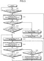
- FIG. 4 is a block diagram illustrating the configuration of the electronic device containing the air volume control device according to the third embodiment.
- An electronic device 20 containing the air volume control device according to the third embodiment includes the electronic component 2, the fan 3, the temperature detecting unit 11, a temperature detecting unit 21, and an air volume control device 22.
- functional units operating similarly to the units illustrated in FIG. 2 are denoted by the same reference numerals and the detailed descriptions thereof will be omitted herein.
- the numbers of electronic components, temperature detecting units, and fans are merely illustrative in the third embodiment, and the numbers thereof are not limited thereto.
- the temperature detecting unit 21 is a thermistor provided in the vicinity of an intake vent of the electronic device, for example.
- the temperature detecting unit 21 periodically detects the temperature of air sucked in by the electronic device 20 after the acceptance of the start of control from a user.
- a temperature of air sucked in by the electronic device 20 is hereinafter referred to as a device intake air temperature Ta.
- the temperature detecting unit 21 periodically measures the device intake air temperature Ta, and outputs the measured device intake air temperature Ta to a recirculation determination unit 23. In one example, if the device intake air temperature Ta is "40°C," the temperature detecting unit 21 outputs "40°C" to the recirculation determination unit 23.
- the air volume control device 22 includes the recirculation determination unit 23 and a fan control unit 24.
- the air volume control device 22 determines whether or not recirculation has occurred, and if there is recirculation, the air volume control device 22 eliminates the recirculation.
- the recirculation determination unit 23 is a control unit for determining whether or not recirculation has occurred based on the device intake air temperature Ta and the number of fan revolutions, and is an example of the determination unit. For example, the recirculation determination unit 23 determines whether or not the device intake air temperature Ta detected by the temperature detecting unit 21 exceeds a predetermined temperature threshold Ts. If it is determined that the device intake air temperature Ta exceeds the predetermined temperature threshold Ts, the recirculation determination unit 23 compares the number of fan revolutions at a time when the device intake air temperature Ta exceeds the predetermined temperature threshold Ts with the number of fan revolutions T seconds prior to that time.
- the time of T seconds is a predetermined value, and a value that can be set arbitrarily by a user. If it is determined that the number of fan revolutions has increased, the recirculation determination unit 23 determines that recirculation has occurred, considering that the device intake air temperature Ta has increased due to an influence of such an increase in the number of revolutions.
- the predetermined temperature threshold Ts can be set arbitrarily by a user, and is, for example, "55°C.”
- the recirculation determination unit 23 starts a process to restore a state with no recirculation. For example, the recirculation determination unit 23 notifies the fan control unit 24 that recirculation has occurred. As a result, the fan control unit 24 decreases the number of fan revolutions. The recirculation determination unit 23 determines whether or not it is in a steady state after the process to restore a state with no recirculation is started.
- the recirculation determination unit 23 determines whether or not the device intake air temperature Ta is lower than the predetermined temperature threshold Ts. If it is determined that the device intake air temperature Ta is lower than the predetermined temperature threshold Ts, the recirculation determination unit 23 determines that recirculation has been eliminated. Then, the recirculation determination unit 23 transitions to a normal control state again.
- the recirculation determination unit 23 notifies the fan control unit 24 that recirculation has not been eliminated yet.
- the fan control unit 24 repeats an operation of further decreasing the number of fan revolutions until it is determined that recirculation has been eliminated.
- the recirculation determination unit 23 determines whether or not the electronic component temperature Tj exceeds the predetermined upper limit.
- the recirculation determination unit 23 notifies the fan control unit 24 that the electronic component temperature Tj exceeds the predetermined upper limit.
- the fan control unit 24 increases the number of fan revolutions until the electronic component temperature Tj becomes lower than the predetermined upper limit.
- the recirculation determination unit 23 continuously determines whether or not it is in a steady state.
- the predetermined upper limit can be set arbitrarily by a user, and is, for example, "80°C.”
- the recirculation determination unit 23 determines that there is no recirculation. If it is determined that the device intake air temperature Ta exceeds the predetermined temperature threshold Ts but the number of fan revolutions has not increased, the recirculation determination unit 23 determines that there is no recirculation. If there is no recirculation, the recirculation determination unit 23 notifies the fan control unit 24 that there is no recirculation.
- the fan control unit 24 calculates the number of fan revolutions suitable for cooling the electronic component 2 based on the electronic component temperature Tj, and changes the applied frequency of the driving voltage to change the number of revolutions of the fan 3. For example, if the fan control unit 24 is notified by the recirculation determination unit 23 that the temperature of air sucked in by the electronic device does not exceed the predetermined temperature threshold Ts, the fan control unit 24 changes the number of revolutions of the fan 3 to the number of fan revolutions suitable for cooling the electronic component 2.
- the fan control unit 24 If the fan control unit 24 is notified by the recirculation determination unit 23 that the temperature of air sucked in by the electronic device exceeds the predetermined threshold but the number of revolutions of the fan 3 has not increased, the fan control unit 24 changes the number of revolutions of the fan 3 to the number of fan revolutions suitable for cooling the electronic component 2.
- the fan control unit 24 If the fan control unit 24 is notified by the recirculation determination unit 23 that recirculation has occurred, the fan control unit 24 performs a process to restore a state with no recirculation by decreasing the number of revolutions of the fan 3. If the fan control unit 24 is notified by the recirculation determination unit 23 that the electronic component temperature Tj exceeds the predetermined upper limit, the fan control unit 24 increases the number of revolutions of the fan 3 until the electronic component temperature Tj becomes lower than the predetermined upper limit. Note that the fan control unit 24 is an example of the decreasing unit and a preventing unit.
- FIG. 5 is a flow chart illustrating the processing procedure by the air volume control device according to the third embodiment.
- the air volume control device 22 determines whether or not the device intake air temperature Ta exceeds the threshold (step S203).
- step S203 determines that the device intake air temperature Ta does not exceed the threshold (step S203, No).
- the air volume control device 22 calculates the number of revolutions of the fan 3 (step S211), and changes the number of revolutions to the calculated number of revolutions (step S212). Thereafter, the air volume control device 22 proceeds to step S202 and performs the processes to follow.
- step S203 determines whether or not the number of fan revolutions has increased from the number of fan revolutions T seconds before (step S204). If it is determined that the number of fan revolutions has not increased from the number of fan revolutions T seconds before (step S204, No), the air volume control device 22 proceeds to the process of step S211, and performs the processes to follow. On the other hand, if it is determined that the number of fan revolutions has increased from the number of fan revolutions T seconds before (step S204, Yes), the air volume control device 22 determines that there is recirculation, and decreases the number of revolutions of the fan 3 (step S205).
- the air volume control device 22 measures the electronic component temperature Tj and the device intake air temperature Ta (step S206). Then, the air volume control device 22 determines whether or not it is in a steady state (step S207). Here, if it is determined to be not in a steady state (step S207, No), the air volume control device 22 determines whether or not the electronic component temperature Tj exceeds the predetermined upper limit (step S209). If it is determined that the electronic component temperature Tj exceeds the predetermined upper limit (step S209, Yes), the air volume control device 22 increases the number of revolutions of the fan 3 until the electronic component temperature Tj becomes lower than the upper limit (step S210). Thereafter, the air volume control device 22 proceeds to step S202 and performs the processes to follow. On the other hand, if it is determined that the electronic component temperature Tj does not exceed the predetermined upper limit (step S209, No), the air volume control device 22 proceeds to step S206 and performs the processes to follow.
- step S207 determines whether or not the device intake air temperature Ta is lower than the threshold (step S208). Then, if it is determined that the device intake air temperature Ta is not lower than the threshold (step S208, No), the air volume control device 22 proceeds to step S205 and performs the processes to follow. On the other hand, if it is determined that the device intake air temperature Ta is lower than the threshold (step S208, Yes), the air volume control device 22 proceeds to step S202 and performs the processes to follow.
- the air volume control device compares the number of fan revolutions at a time when the device intake air temperature Ta exceeds the predetermined temperature threshold Ts with the number of fan revolutions T seconds prior to that time. Subsequently, if the number of revolutions has increased from the number of fan revolutions T seconds before, the air volume control device determines that there is recirculation. If it is determined that there is recirculation, the air volume control device decreases the number of fan revolutions to eliminate the recirculation. Therefore, it is possible to prevent an increase in the electronic component temperature Tj.
- the air volume control device determines that the electronic component is thermally at risk, and therefore increases the number of revolutions of the fan 3. Therefore, when the electronic component is thermally at risk, the air volume control device according to the third embodiment can prevent a further increase in the electronic component temperature Tj.
- the method for determining whether or not the cooling capacity of an electronic device fulfills a predetermined cooling capacity by determining whether or not recirculation has occurred in the electronic device alone is installed in a rack in a data center.
- an upper part of the rack sucks in warm air
- a lower part of the rack sucks in cooling air blown out from an under floor. That is, there is a temperature difference between the temperature of air sucked in by the uppermost part of the rack and the temperature of air sucked in by the lowermost part of the rack.
- the fourth embodiment describes a case in which an air volume control device determines whether or not a temperature difference ⁇ Ta between an uppermost part of a rack and a lowermost part of the rack exceeds a predetermined threshold to determine whether or not the cooling capacity of an electronic device fulfills a predetermined cooling capacity. For example, if the temperature difference ⁇ Ta between the uppermost part of the rack and the lowermost part of the rack exceeds the predetermined threshold, the air volume control device determines that there is recirculation, and therefore decreases the number of fan revolutions until ⁇ Ta becomes lower than the predetermined threshold.
- a configuration of a rack containing an air volume control device according to the fourth embodiment, a processing procedure by the air volume control device according to the fourth embodiment, and an advantageous effect of the fourth embodiment will be described in order.
- FIG. 6 is a block diagram illustrating the configuration of the rack containing the air volume control device according to the fourth embodiment.
- a rack 30 containing the air volume control device according to the fourth embodiment is a housing of 600 mm long, 1000 mm wide, and 2000 mm in height, for example.
- the rack 30 includes fans 3a, 3b, and 3c, temperature detecting units 31 and 32, electronic devices 33a, 33b, 33c, and 33d, and an air volume control device 34.
- the rack is an example of the housing.
- functional units operating similarly to the units illustrated in FIG.
- the temperature detecting unit 31 is a thermistor provided at an air intake position of the electronic device positioned in the uppermost part of the rack 30, for example.
- the temperature detecting unit 31 detects the temperature of air taken in by the electronic device positioned in the uppermost part of the rack 30 after the acceptance of the start of control from a user.
- a temperature of air taken in by the electronic device positioned in the uppermost part of the rack 30 is hereinafter referred to as a device upper part intake air temperature Ta1.
- the temperature detecting unit 31 periodically measures the device upper part intake air temperature Ta1, and outputs the measured device upper part intake air temperature Ta1 to a recirculation determination unit 35. In one example, when the device upper part intake air temperature Ta1 is "40°C,” the temperature detecting unit 31 outputs "40°C" to the recirculation determination unit 35.
- the temperature detecting unit 32 is a thermistor provided at an air intake position of the electronic device positioned in the lowermost part of the rack 30, for example.
- the temperature detecting unit 32 detects the temperature of air taken in by the electronic device positioned in the lowermost part of the rack 30 after the acceptance of the start of control from a user.
- a temperature of air taken in by the electronic device positioned in the lowermost part of the rack 30 is hereinafter referred to as a device lower part intake air temperature Ta2.
- the temperature detecting unit 32 periodically measures the device lower part intake air temperature Ta2, and outputs the measured device lower part intake air temperature Ta2 to the recirculation determination unit 35. In one example, when the device lower part intake air temperature Ta2 is "30°C,” the temperature detecting unit 32 outputs "30°C" to the recirculation determination unit 35.
- the electronic device 33a includes an electronic component 2a and a temperature detecting unit 11a. Since the electronic component 2a is similar to the electronic component 2 and the temperature detecting unit 11a is similar to the temperature detecting unit 11, detailed descriptions thereof will be omitted herein.
- the air volume control device 34 includes the recirculation determination unit 35 and a fan control unit 36.
- the air volume control device 34 determines whether or not recirculation has occurred, and if there is recirculation, it performs control to eliminate the recirculation.
- the recirculation determination unit 35 is a control unit for calculating a temperature difference ⁇ Ta between the device upper part intake air temperature Ta1 notified by the temperature detecting unit 31 and the device lower part intake air temperature Ta2 notified by the temperature detecting unit 32, and determining whether or not the calculated temperature difference ⁇ Ta exceeds a predetermined threshold. Note that the recirculation determination unit 35 is an example of the determination unit.
- the recirculation determination unit 35 determines that recirculation has occurred. In such a case, the recirculation determination unit 35 starts a process to restore a state with no recirculation. For example, the recirculation determination unit 35 notifies the fan control unit 36 that recirculation has occurred. As a result, the fan control unit 36 decreases the number of fan revolutions.
- the predetermined threshold of the temperature difference ⁇ Ta can be arbitrarily set by a user, and is "10°C," for example.
- the recirculation determination unit 35 determines whether or not it is in a steady state after the process to restore a state with no recirculation is started. If it is determined to be in a steady state, the recirculation determination unit 35 determines whether or not the temperature difference ⁇ Ta between the device upper part intake air temperature Ta1 and the device lower part intake air temperature Ta2 is lower than the predetermined threshold.
- the recirculation determination unit 35 determines that recirculation has been eliminated. Then, the recirculation determination unit 35 transitions to a normal control state again.
- the recirculation determination unit 35 determines that recirculation has not been eliminated yet. In such a case, the recirculation determination unit 35 notifies the fan control unit 36 that recirculation has not been eliminated yet. As a result, the fan control unit 36 repeats an operation of further decreasing the number of fan revolutions until it is determined that recirculation has been eliminated.
- the recirculation determination unit 35 continuously determines whether or not it is in a steady state.
- the recirculation determination unit 35 determines that there is no recirculation. In such a case, the recirculation determination unit 35 notifies the fan control unit 36 that there is no recirculation.
- the fan control unit 36 calculates the number of fan revolutions suitable for cooling respective electronic components 2a to 2d of the electronic devices 33a to 33d from the electronic component temperature Tj, and changes the applied frequency of the driving voltage to change the number of revolutions of the fans 3a to 3c. For example, if the fan control unit 36 is notified by the recirculation determination unit 35 that the temperature difference ⁇ Ta between the device upper part intake air temperature Ta1 and the device lower part intake air temperature Ta2 does not exceed the predetermined threshold, the fan control unit 36 changes the number of revolutions of the fans 3a to 3c to the number of fan revolutions suitable for cooling the electronic components 2a to 2d.
- the fan control unit 36 If the fan control unit 36 is notified by the recirculation determination unit 35 that there is recirculation, the fan control unit 36 starts a process to restore a state with no exhaust air recirculation by decreasing the number of revolutions of the fans 3a to 3c. Moreover, if the fan control unit 36 is notified by the recirculation determination unit 35 that recirculation has not been eliminated yet, the fan control unit 36 decreases the number of revolutions of the fans 3a to 3c. Note that the fan control unit 36 is an example of the decreasing unit.
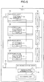
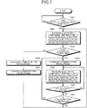
- FIG. 7 is a flow chart illustrating the processing procedure by the air volume control device according to the fourth embodiment.
- the air volume control device 34 if the air volume control device 34 accepts start of control from a user (step S301, Yes), the air volume control device 34 measures the electronic component temperature Tj, the device upper part intake air temperature Ta1, and the device lower part intake air temperature Ta2 (step S302). Note that the air volume control device 34 thereafter measures the electronic component temperature Tj, the device upper part intake air temperature Ta1, and the device lower part intake air temperature Ta2 at regular time intervals.
- the air volume control device 34 determines whether or not the temperature difference ⁇ Ta between the device upper part intake air temperature Ta1 and the device lower part intake air temperature Ta2 exceeds the predetermined threshold (step S303).
- the air volume control device 34 calculates the number of revolutions of the fans 3a to 3c (step S308). Then, the air volume control device 34 changes the number of revolutions of the fans 3a to 3c to the calculated number of revolutions (step S309). Thereafter, the air volume control device 34 proceeds to step S302 and performs the processes to follow.
- step S303 if it is determined that the temperature difference ⁇ Ta between the device upper part intake air temperature Ta1 and the device lower part intake air temperature Ta2 exceeds the predetermined threshold (step S303, Yes), the air volume control device 34 decreases the number of revolutions of the fans 3a to 3c (step S304). Then, the air volume control device 34 measures the electronic component temperature Tj, the device upper part intake air temperature Ta1, and the device lower part intake air temperature Ta2 (step S305). Subsequently, the air volume control device 34 determines whether or not it is in a steady state (step S306).
- step S306, No If it is determined to be not in a steady state (step S306, No), the air volume control device 34 proceeds to step S305 and performs the processes to follow. On the other hand, if it is determined to be in a steady state (step S306, Yes), the air volume control device 34 determines whether or not the temperature difference ⁇ Ta between the device upper part intake air temperature Ta1 and the device lower part intake air temperature Ta2 is lower than the predetermined threshold (step S307).
- step S307 If it is determined that the temperature difference ⁇ Ta between the device upper part intake air temperature Ta1 and the device lower part intake air temperature Ta2 is lower than the predetermined threshold (step S307, Yes), the air volume control device 34 proceeds to step S302 and performs the processes to follow. On the other hand, if it is determined that the temperature difference ⁇ Ta between the device upper part intake air temperature Ta1 and the device lower part intake air temperature Ta2 is not lower than the predetermined threshold (step S307, No), the air volume control device 34 proceeds to step S304 and performs the processes to follow.
- the air volume control device 34 determines that there is recirculation.
- the air volume control device decreases the number of fan revolutions to eliminate the recirculation. Therefore, it is possible to prevent an increase in the electronic component temperature Tj.
- the air volume control device disclosed in the present application may be carried out in various different modes in addition to the embodiments described above.
- the fifth embodiment describes another embodiment of the air volume control device disclosed in the present application.
- the air volume control device determines whether or not there is recirculation. For example, it has been described that the air volume control device according to the second embodiment determines whether or not the CPU utilization has changed, and if there is no change in CPU utilization, it determines whether or not there is recirculation.
- the method for determining whether or not there is a load on an electronic component by the air volume control device is not limited thereto.
- the air volume control device may be designed and configured so that the air volume control device monitors the number of signals or a memory usage per unit time instead of CPU utilization, and if these have not changed, it determines whether or not there is recirculation.
- the air volume control device can combine, as desired, the methods for determining whether or not recirculation has occurred, which have been described in the embodiments.
- the electronic devices 33a and 33b in the fourth embodiment determine whether or not recirculation has occurred based on the temperature difference ⁇ Ta between the device upper part intake air temperature Ta1 and the device lower part intake air temperature Ta2, which is the method described in the fourth embodiment.
- the electronic device 33c determines whether or not recirculation has occurred based on the device intake air temperature Ta, which is the method described in the third embodiment.
- the electronic device 33d determines whether or not recirculation has occurred based on the electronic component temperature Tj, which is the method described in the second embodiment.
- the air volume control devices in the second and fourth embodiments may be designed and configured so that if the electronic component temperature Tj exceeds the preset upper limit temperature, they determine that the electronic component is thermally at risk, thereby increasing the number of revolutions of the fans 3a to 3c.
- the components illustrated in the figures are functionally conceptual, and they are not necessarily required to be physically configured as illustrated in the figures.
- the load measuring unit 13 and the recirculation determination unit 15 may be integrated together.
- all or a desired part of the processing functions performed by the devices may be realized by a CPU and a program analyzed and executed by the CPU, or may be realized as a hardware by a wired logic.
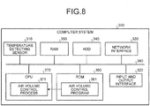
- FIG. 8 is a diagram illustrating a computer system for executing an air volume control program.
- a computer system 300 includes a temperature detecting sensor 310 for detecting a temperature of an electronic component, and an input and output interface 320 for accepting various settings from a user or notifying a status of the computer system and the like.
- the computer system 300 also includes a network interface 330 for transmitting and receiving data to and from other devices, an HDD 340, a RAM 350, a ROM (read only memory) 360, a CPU 370, and a bus 380.
- the respective devices 310 to 370 are connected to the bus 380.
- the ROM 360 prestores an air volume control program 361 exerting functions similar to those of the determination unit 5 and the decreasing unit 6 illustrated in FIG. 1 .
- the CPU 370 reads out the air volume control program 361 from the ROM 360, and executes it as an air volume control process 371. That is, the air volume control process 371 performs operations similar to those of the determination unit 5 and the decreasing unit 6 illustrated in FIG. 1 .
- the air volume control program 361 described above is not necessarily required to be stored in the ROM 360.
- the air volume control program 361 may be stored in a "transportable physical medium” such as a flexible disk (FD), a CD-ROM, an MO disk, a DVD disk, a magneto-optical disk, or an IC card to be inserted in the computer system 300.
- the air volume control program 361 may be stored in a "fixed physical medium” such as a hard disk drive (HDD) provided inside or outside of the computer system 300.
- HDD hard disk drive
- the air volume control program 361 may be stored in "another computer system" connected to the computer system 300 via a public line, the Internet, a LAN (local area network), a WAN (wide area network), or the like. Then, the computer system 300 may read out the program therefrom for execution.
- this program is stored in a recording medium such as the above-described "transportable physical medium,” “fixed physical medium,” or “communication medium” in a computer-readable form. Then, the computer system 300 reads out the program from such a recording medium and executes it, thereby carrying out functions similar to those in the above-described embodiments.
- the program referred in this another embodiment is not limited to being executed by the computer system 300.
- the present invention can be similarly applied also to a case where another computer system or server executes the program or a case where they execute the program in cooperation.
Landscapes
- Engineering & Computer Science (AREA)
- Physics & Mathematics (AREA)
- General Engineering & Computer Science (AREA)
- Theoretical Computer Science (AREA)
- Microelectronics & Electronic Packaging (AREA)
- Combustion & Propulsion (AREA)
- Mechanical Engineering (AREA)
- Chemical & Material Sciences (AREA)
- Human Computer Interaction (AREA)
- General Physics & Mathematics (AREA)
- Thermal Sciences (AREA)
- Signal Processing (AREA)
- Fluid Mechanics (AREA)
- Computer Hardware Design (AREA)
- Fuzzy Systems (AREA)
- Mathematical Physics (AREA)
- Cooling Or The Like Of Electrical Apparatus (AREA)
- Cooling Or The Like Of Semiconductors Or Solid State Devices (AREA)
Abstract
An air volume control device (4) determines whether or not a cooling capacity of an electronic device fulfills a predetermined cooling capacity. Then, if it is determined that the cooling capacity of the electronic device is failing to fulfill the predetermined cooling capacity, the air volume control device (4) decreases the number of revolutions of a fan for cooling the electronic device.
For example, the air volume control device (4) compares a temperature of a heating element provided in the electronic device before a change in the number of revolutions of the fan with that after the change in the number of revolutions of the fan. If the temperature of the heating element is increased when the number of revolutions of the fan is increased, the air volume control device (4) determines that the cooling capacity of the electronic device is failing to fulfill the predetermined cooling capacity.
Description
- The embodiments discussed herein are directed to an air volume control device, an air volume control method, and an air volume control program.
- In recent years, there have been cases such that electronic devices such as servers are managed collectively in a data center or the like. With reference to
FIG. 9 , an exemplary configuration of a data center will be described.FIG. 9 is a diagram illustrating an exemplary configuration of a data center. As illustrated inFIG. 9 , in adata center 901, a plurality ofracks 902a to 902f are installed in columns with front surfaces and rear surfaces thereof facing the same directions, respectively. Then, a plurality of electronic devices such as servers are installed in each of theracks 902a to 902f. - Moreover, in an electronic device such as a server, an amount of heat generation in an electronic component such as a CPU (central processing unit) has been continuously increasing. If a temperature of an electronic component as represented by a CPU becomes high, the electronic device may be operationally unstable. Therefore, in the data center, the electronic components are appropriately cooled so that the electronic devices can operate stably.
- In the example illustrated in
FIG. 9 , cooling air of 20 to 25°C, for example, is blown out from an underfloor 903 by an air-conditioning equipment 904, and is supplied to theracks 902a to 902f via floor surface aperturedpanels 905. The electronic devices mounted in theracks 902a to 902f rotate fans included therein to take in the cooling air from outside of housings of the electronic devices, thereby cooling the electronic components within the housings. - An amount of heat generation in a CPU changes in accordance with an amount of processing load. Therefore in the data center, the electronic device changes the number of revolutions of the fan in accordance with the amount of heat generation in the CPU so as to change an amount of cooling air to be taken in from outside of the electronic device. For example, the number of revolutions of the fan is set in accordance with an intake air temperature of the electronic device or a CPU temperature.
- Patent Literature 1: Japanese Laid-open Patent Publication No.
11-264599 - Patent Literature 2: Japanese Laid-open Patent Publication No.
02-123413 - However, the above-described conventional technique has a problem that there is a case where it is not possible to prevent an increase in electronic component temperature.
- Specifically, in the conventional data center, a sufficient amount of cooling air has been supplied to racks via floor surface apertured panels with respect to an amount of cooling air taken in inside the housings of the electronic devices by the electronic devices. Thus, the electronic devices take in inside the housings thereof the cooling air supplied to the racks via the floor surface apertured panels, thereby appropriately cooling the electronic components of the electronic devices.
- In recent years, however, a rack in a data center mounts a blade server having an improved processing capability and a larger amount of heat generation as compared to a conventional server. In such a data center, there is a case where an amount of air taken in by electronic devices becomes greater than cooling air supplied to the racks via the floor surface apertured panels. In such a case, there occurs a hot spot phenomenon such that warm exhaust air exhausted by the electronic devices is taken in again by the electronic devices together with the cooling air supplied to the racks. Such a situation that discharge from an electronic device is taken in again by the electronic device is called "exhaust air recirculation."
- Since the conventional data center does not deal with the possibility of an environment in which exhaust air recirculation occurs, exhaust air recirculation cannot be eliminated. Therefore, if a hot spot phenomenon is generated, even when the number of revolutions of the fan is increased so as to increase an amount of cooling air to be taken in by the electronic device, the electronic device takes in exhaust air therefrom together with the cooling air. Thus, due to the exhaust air from the electronic device, a temperature of the cooling air taken in by the electronic device increases. As a result, it fails to appropriately cool the electronic component and the temperature thereof thus increases.
- With reference to
FIG. 10 , there is illustrated an example.FIG. 10 is a diagram illustrating changes in an electronic component temperature when the number of fan revolutions is varied in a data center where racks having blade servers mounted therein are arranged. In cases of the number of revolutions R1 to R3 illustrated inFIG. 10 , an amount of cooling air supplied to the racks via the floor surface apertured panels is sufficient for an amount of cooling air taken in by the electronic devices. In such a case, by increasing the number of revolutions from R1 to R2, and then to R3, an air volume of the electronic device increases, and the electronic component temperature is therefore decreased from 98°C to 71°C. - On the other hand, in cases of the number of revolutions R4 to R7 illustrated in
FIG. 10 , an amount of air taken in by the electronic devices becomes greater than the cooling air supplied to the racks via the floor surface apertured panels. In such a case, exhaust air recirculation occurs, and the electronic component temperature is increased from 86°C to 90°C. Thus, in the conventional data center, it is not possible to prevent an increase in electronic component temperature when there is exhaust air recirculation. - Accordingly, it is an object in one aspect of an embodiment of the invention to provide an air volume control device, an air volume control method, and an air volume control program capable of preventing an increase in electronic component temperature.
- According to an aspect of an embodiment of the invention, an air volume control device includes a determination unit that determines whether or not a cooling capacity of an electronic device fulfills a predetermined cooling capacity, a decreasing unit that decreases the number of revolutions of a fan for cooling the electronic device if the determination unit determines that the cooling capacity of the electronic device is failing to fulfill the predetermined cooling capacity.
-
-
FIG. 1 is a block diagram illustrating a configuration of an electronic device containing an air volume control device according to a first embodiment; -
FIG. 2 is a block diagram illustrating a configuration of an electronic device containing an air volume control device according to a second embodiment; -
FIG. 3 is a flow chart illustrating a processing procedure by the air volume control device according to the second embodiment; -
FIG. 4 is a block diagram illustrating a configuration of an electronic device containing an air volume control device according to a third embodiment; -
FIG. 5 is a flow chart illustrating a processing procedure by the air volume control device according to the third embodiment; -
FIG. 6 is a block diagram illustrating a configuration of a rack containing an air volume control device according to a fourth embodiment; -
FIG. 7 is a flow chart illustrating a processing procedure by the air volume control device according to the fourth embodiment; -
FIG. 8 is a diagram illustrating a computer system for executing an air volume control program; -
FIG. 9 is a diagram illustrating an exemplary configuration of a data center; and -
FIG. 10 is a diagram illustrating changes in electronic component temperature when the number of fan revolutions is varied in a data center where racks having blade servers mounted therein are arranged. - Preferred embodiments of the present invention will be explained with reference to accompanying drawings. It is to be understood that the present invention is not limited by these embodiments. Although in the following embodiments, a 1U server, which is a type of blade server (or rack-mount server), is employed as an example of an electronic device, the present invention is not limited to this and can be applied to computer devices in general having other housing sizes or housing shapes.
-
FIG. 1 is a block diagram illustrating a configuration of an electronic device containing an air volume control device according to the first embodiment. As illustrated inFIG. 1 , anelectronic device 1 has anelectronic component 2, afan 3, and an airvolume control device 4. Theelectronic device 1 is a 1U server containing theelectronic component 2 inside a housing of about 45 mm in height × about 19 inches in width × about 540 mm in depth, for example. Note that the numbers of electronic components and fans are merely illustrative in the first embodiment, and the numbers thereof are not limited thereto. - Examples of the
electronic component 2 include a CPU (central processing unit), a RAM (random access memory), and an HDD (hard disk drive). Theelectronic component 2 radiates heat generated from a surface of theelectronic component 2 to air taken in inside theelectronic device 1 by thefan 3 via a radiator such as a heat sink. Note that theelectronic component 2 is an example of a heating element. - The
fan 3 is an axial flow fan of a PWM (pulse width modulation) type or the like, for example. When an applied frequency of a driving voltage is changed by a decreasingunit 6 to be described later, thefan 3 changes the number of revolutions thereof. For example, when a temperature of theelectronic component 2 is increased, thefan 3 increases the number of revolutions thereof to increase the wind speed of the fan, thereby cooling theelectronic component 2. - The air
volume control device 4 includes adetermination unit 5 and thedecreasing unit 6. Thedetermination unit 5 determines whether or not the cooling capacity of theelectronic device 1 fulfills a predetermined cooling capacity. For example, thedetermination unit 5 determines whether or not air exhausted from theelectronic device 1 has been recirculated into air sucked in by theelectronic device 1. If it is determined that recirculation has occurred, thedetermination unit 5 determines that the cooling capacity of theelectronic device 1 is failing to fulfill the predetermined cooling capacity. - If it is determined by the
determination unit 5 that the cooling capacity of theelectronic device 1 is failing to fulfill the predetermined cooling capacity, the decreasingunit 6 decreases the number of revolutions of thefan 3 for cooling theelectronic device 1. - As described above, if air exhausted from the
electronic device 1 is recirculated into cooling air sucked in by theelectronic device 1, thedetermination unit 5 determines that the cooling capacity of theelectronic device 1 is failing to fulfill the predetermined cooling capacity. If it is determined by thedetermination unit 5 that the cooling capacity of theelectronic device 1 is failing to fulfill the predetermined cooling capacity, the decreasingunit 6 decreases the number of revolutions of thefan 3, thereby eliminating the recirculation. As a result, if it is determined that the cooling capacity of theelectronic device 1 is failing to fulfill the predetermined cooling capacity, the airvolume control device 4 according to the first embodiment can prevent an increase in temperature of theelectronic component 2 by decreasing the number of revolutions of thefan 3 for cooling theelectronic component 2. - Next, in the second embodiment, a case will be described where an air volume control device monitors a temperature of an electronic component and determines whether or not there is recirculation, thereby determining whether or not the cooling capacity of an electronic device fulfills a predetermined cooling capacity. The air volume control device according to the second embodiment performs feedback control such that the number of fan revolutions is increased in accordance with an increase in the temperature of the electronic component and the number of fan revolutions is decreased in accordance with a decrease in the temperature of the electronic component during normal times. The air volume control device determines whether or not there is recirculation at a period of time during which there is no change in load on the electronic component. If it is determined that there is recirculation, the air volume control device performs control for restoring the number of fan revolutions to obtain a state where no recirculation occurs. Here, a configuration of the electronic device containing the air volume control device according to the second embodiment, a processing procedure by the air volume control device according to the second embodiment, and an advantageous effect of the second embodiment will be described in order.
- Configuration of electronic device containing air volume control device according to the second embodiment
- Next, with reference to
FIG. 2 , the configuration of the electronic device containing the air volume control device according to the second embodiment will be described.FIG. 2 is a block diagram illustrating the configuration of the electronic device containing the air volume control device according to the second embodiment. Anelectronic device 10 according to the second embodiment includes theelectronic component 2, thefan 3, atemperature detecting unit 11, and an airvolume control device 12. Theelectronic device 10 is a 1U server containing theelectronic component 2 and the like inside a housing of about 45 mm in height × about 19 inches in width × about 540 mm in depth, for example. Note that functional units operating similarly to the units illustrated inFIG. 1 are denoted by the same reference numerals and the detailed descriptions thereof will be omitted. Moreover, the numbers of electronic components, temperature detecting units, and fans are merely illustrative in the second embodiment, and the numbers thereof are not limited thereto. - The
temperature detecting unit 11 is a thermal diode inside an LSI, for example, and periodically measures the temperature of theelectronic component 2 after the acceptance of an instruction for starting control from a user via an accepting unit not illustrated in the figure. Note that the temperature of theelectronic component 2 is hereinafter referred to as an electronic component temperature Tj . For example, thetemperature detecting unit 11 periodically measures the electronic component temperature Tj, converts the measured electronic component temperature Tj into an electrical signal, and outputs the electrical signal to arecirculation determination unit 15 and afan control unit 14. In one example, where the electronic component temperature Tj is "50°C," thetemperature detecting unit 11 outputs to thefan control unit 14 and therecirculation determination unit 15 that the electronic component temperature Tj is "50°C." - The air
volume control device 12 includes aload measuring unit 13, thefan control unit 14, and therecirculation determination unit 15. The airvolume control device 12 includes an internal memory for storing a control program, a program specifying various processing procedures, and data. For example, the airvolume control device 12 is an integrated circuit such as ASIC (application specific integrated circuit) or FPGA (field programmable gate array), or an electronic circuit such as a CPU or an MPU. - The
load measuring unit 13 measures a load on theelectronic component 2, and determines whether or not the load on theelectronic component 2 has changed. For example, where theelectronic component 2 is a CPU, theload measuring unit 13 periodically measures CPU utilization after the acceptance of an instruction for starting control from a user via an accepting unit not illustrated in the figure. Then, theload measuring unit 13 compares the currently-measured CPU utilization with the previously-measured CPU utilization to determine whether or not the CPU utilization has changed. Note that theload measuring unit 13 is an example of a measuring unit. - If it is determined that there is no change in CPU utilization, the
load measuring unit 13 notifies thefan control unit 14 and therecirculation determination unit 15 of the measured CPU utilization and that there is no change in CPU utilization. Moreover, if it is determined that there is a change in CPU utilization, theload measuring unit 13 notifies thefan control unit 14 and therecirculation determination unit 15 that the CPU utilization has changed. - The
fan control unit 14 is a control unit for changing an applied frequency of a driving voltage to change the number of revolutions of thefan 3, and it is an example of the decreasing unit. For example, if thefan control unit 14 is notified by theload measuring unit 13 that there is a change in CPU utilization, thefan control unit 14 calculates the number of fan revolutions suitable for cooling the electronic component from the electronic component temperature Tj, and changes the number of revolutions of thefan 3 to the calculated number of revolutions. Note that the number of fan revolutions in accordance with the electronic component temperature Tj is set in advance by a user. Therefore, thefan control unit 14 can calculate the number of fan revolutions suitable for cooling the electronic component from the electronic component temperature Tj. - Moreover, if the
fan control unit 14 is notified by therecirculation determination unit 15 that determination regarding whether or not recirculation has occurred is to be started, thefan control unit 14 changes the number of revolutions of thefan 3. For example, thefan control unit 14 increases or decreases the number of revolutions of thefan 3. Moreover, if thefan control unit 14 is notified by therecirculation determination unit 15 that recirculation has occurred, thefan control unit 14 decreases the number of revolutions of thefan 3. - The
recirculation determination unit 15 is a control unit for determining whether or not recirculation has occurred when therecirculation determination unit 15 is notified by theload measuring unit 13 that there is no change in CPU utilization, and it is an example of the determination unit. For example, if the electronic component temperature Tj is decreased after the number of fan revolutions is reduced by thefan control unit 14, therecirculation determination unit 15 determines that recirculation has occurred. If the electronic component temperature Tj is increased after the number of fan revolutions is increased by thefan control unit 14, therecirculation determination unit 15 determines that recirculation has occurred. Hereinafter, an operation by therecirculation determination unit 15 will be described in detail. - First, if the
recirculation determination unit 15 is notified by theload measuring unit 13 that there is no change in CPU utilization, therecirculation determination unit 15 notifies thefan control unit 14 that determination regarding whether or not recirculation has occurred is to be started. As a result, thefan control unit 14 changes the number of revolutions of thefan 3. Note that a case where therecirculation determination unit 15 determines whether or not recirculation has occurred after the number of revolutions of thefan 3 is increased by thefan control unit 14 will be explained herein. - The
recirculation determination unit 15 determines whether or not it is in a steady state after the number of fan revolutions is increased by thefan control unit 14. A steady state used herein refers to a state in which thefan 3 is stably operated with the number of revolutions being restored to a certain number of revolutions after the number of revolutions is increased by thefan 3 to the changed set value. If it is determined to be in a steady state, therecirculation determination unit 15 determines whether or not the electronic component temperature Tj has increased as compared to that before the increase in the number of fan revolutions, and thus determines whether or not recirculation has occurred. - If it is determined that the electronic component temperature Tj has not increased as compared to that before the increase in the number of fan revolutions, the
recirculation determination unit 15 determines that there is no recirculation, and transitions to a normal control state again. On the other hand, if it is determined that the electronic component temperature Tj has increased as compared to that before the increase in the number of fan revolutions, therecirculation determination unit 15 determines that recirculation has occurred and starts a process of restoring the number of fan revolutions to obtain a state with no recirculation. For example, therecirculation determination unit 15 notifies thefan control unit 14 that recirculation has occurred. As a result, thefan control unit 14 decreases the number of fan revolutions. - After the process of restoring a state with no recirculation is started, the
recirculation determination unit 15 determines whether or not it is in a steady state. If it is determined to be in a steady state, therecirculation determination unit 15 determines whether or not the electronic component temperature Tj has decreased as compared to that before the decrease in the number of fan revolutions. If it is determined that the electronic component temperature Tj has decreased as compared to that before the decrease in the number of fan revolutions, therecirculation determination unit 15 determines that recirculation has been eliminated, and transitions to a normal control state again. On the other hand, if it is determined that the electronic component temperature Tj has not decreased as compared to that before the decrease in the number of fan revolutions, therecirculation determination unit 15 determines that recirculation has not been eliminated yet, and repeats an operation of further decreasing the number of fan revolutions until it is determined that recirculation has been eliminated. - If it is determined to be not in a steady state after determination regarding whether or not recirculation has occurred is started and after the process of restoring a state with no recirculation is started, the
recirculation determination unit 15 determines whether or not there is a change in CPU utilization notified by theload measuring unit 13. If therecirculation determination unit 15 is notified by theload measuring unit 13 that there is no change in CPU utilization, therecirculation determination unit 15 continuously determines whether or not it is in a steady state. - Note that if the
recirculation determination unit 15 is notified by theload measuring unit 13 that there is a change in CPU utilization, therecirculation determination unit 15 does not perform the process of determining whether or not recirculation has occurred. Moreover, if therecirculation determination unit 15 is notified by theload measuring unit 13 that there is a change in CPU utilization after the process of determining whether or not recirculation has occurred is started, therecirculation determination unit 15 terminates the process of determining whether or not recirculation has occurred. Similarly, if therecirculation determination unit 15 is notified by theload measuring unit 13 that there is a change in CPU utilization after the process of restoring a state with no recirculation is started, therecirculation determination unit 15 terminates the process of restoring a state with no recirculation. - Processing procedure by air volume control device according to the second embodiment
- Next, with reference to
FIG. 3 , a processing procedure by the airvolume control device 12 according to the second embodiment will be described.FIG. 3 is a flow chart illustrating the processing procedure by the air volume control device according to the second embodiment. - As illustrated in
FIG. 3 , if the airvolume control device 12 accepts start of control from a user (step S101, Yes), the airvolume control device 12 measures the electronic component temperature Tj and the CPU utilization (step S102). Note that the airvolume control device 12 thereafter measures the electronic component temperature Tj and the CPU utilization periodically. - Subsequently, the air
volume control device 12 determines whether or not there is a change in CPU utilization (step S103). Here, if it is determined that there is a change in CPU utilization (step S103, Yes), the airvolume control device 12 calculates the number of revolutions of thefan 3 suitable for cooling the electronic component (step S112), and changes the number of revolutions to the calculated number of revolutions (step S113). Thereafter, the airvolume control device 12 proceeds to step S102, and performs processes to follow. - On the other hand, if it is determined that there is no change in CPU utilization in step S103 (step S103, No), the air
volume control device 12 increases the number of revolutions of the fan 3 (step S104), and measures the electronic component temperature Tj and the CPU utilization (step S105). - Then, the air
volume control device 12 determines whether or not it is in a steady state (step S106). Here, if it is determined to be not in a steady state (step S106, No), the airvolume control device 12 determines whether or not there is a change in CPU utilization (step S114). If it is determined that there is a change in CPU utilization (step S114, Yes), the airvolume control device 12 proceeds to step S112, and performs the processes to follow. On the other hand, if it is determined that there is no change in CPU utilization (step S114, No), the airvolume control device 12 proceeds to step S105, and performs the processes to follow. - On the other hand, if it is determined to be in a steady state (step S106, Yes), the air
volume control device 12 determines whether or not the electronic component temperature Tj has increased (step S107). Here, if it is determined that the electronic component temperature Tj has not increased (step S107, No), the airvolume control device 12 proceeds to step S102, and performs the processes to follow. On the other hand, if it is determined that the electronic component temperature Tj has increased (step S107, Yes), the airvolume control device 12 decreases the number of revolutions of the fan 3 (step S108). - Subsequently, the air
volume control device 12 measures the electronic component temperature Tj and the CPU utilization (step S109). Then, the airvolume control device 12 determines whether or not it is in a steady state (step S110). Here, if it is determined to be not in a steady state (step S110, No), the airvolume control device 12 determines whether or not there is a change in CPU utilization (step S115). If it is determined that there is a change in CPU utilization (step S115, Yes), the airvolume control device 12 proceeds to step S112, and performs the processes to follow. On the other hand, if it is determined that there is no change in CPU utilization (step S115, No), the airvolume control device 12 proceeds to step S109, and performs the processes to follow. - If it is determined to be in a steady state in step S110, the air
volume control device 12 determines whether or not the electronic component temperature Tj has decreased as compared to that before the decrease in the number of fan revolutions (step S111). Here, if it is determined that the electronic component temperature Tj has not decreased as compared to that before the decrease in the number of fan revolutions (step S111, No), the airvolume control device 12 proceeds to step S108 and performs the processes to follow. On the other hand, if it is determined that the electronic component temperature Tj has decreased as compared to that before the decrease in the number of fan revolutions (step S111, Yes), the airvolume control device 12 proceeds to step S102 and performs the processes to follow. - Advantageous effect of second embodiment
- As described above, according to the second embodiment, the air
volume control device 12 can determine whether or not there is recirculation based on an increase or decrease in the electronic component temperature Tj between before and after a change in the number of fan revolutions. If it is determined that there is recirculation, the airvolume control device 12 decreases the number of fan revolutions to eliminate recirculation. Thus, it is possible to prevent an increase in the electronic component temperature Tj. - Moreover, if there is no change in load on the electronic component, the air
volume control device 12 according to the second embodiment determines whether or not there is recirculation. Thus, if there is an increase in the CPU utilization and the electronic component temperature Tj is thereby increased, for example, the airvolume control device 12 does not determine whether or not recirculation has occurred, and changes the number of fan revolutions to that calculated from the electronic component temperature Tj and suitable for cooling the electronic component. Therefore, when there is no change in load on the electronic component, the airvolume control device 12 according to the second embodiment can prevent an increase in the electronic component temperature by determining whether or not recirculation has occurred. When there is a change in load on the electronic component, the airvolume control device 12 according to the second embodiment can cool the electronic component with the number of fan revolutions suitable for cooling the electronic component. - The second embodiment described an example in which the air
volume control device 12 measures the electronic component temperature Tj to determine whether or not there is recirculation and thereby determine whether or not the cooling capacity of the electronic device fulfills the predetermined cooling capacity. By the way, if recirculation occurs in a data center, the temperature of air sucked in by the electronic device is also increased. Therefore, the air volume control device may determine whether or not recirculation has occurred based on the temperature of air sucked in by the electronic device. - Thus, the third embodiment describes a case where an air volume control device detects a temperature of air sucked in by an electronic device and determines whether or not recirculation has occurred based on the detected temperature of air sucked in by the electronic device, thereby determining whether or not the cooling capacity of the electronic device fulfills a predetermined cooling capacity. Here, a configuration of an electronic device containing the air volume control device according to the third embodiment, a processing procedure by the air volume control device according to the third embodiment, and an advantageous effect of the third embodiment will be described in order.
- Configuration of electronic device containing air volume control device according to the third embodiment Next, with reference to
FIG. 4 , the configuration of the electronic device containing the air volume control device according to the third embodiment will be described.FIG. 4 is a block diagram illustrating the configuration of the electronic device containing the air volume control device according to the third embodiment. Anelectronic device 20 containing the air volume control device according to the third embodiment includes theelectronic component 2, thefan 3, thetemperature detecting unit 11, atemperature detecting unit 21, and an airvolume control device 22. Note that functional units operating similarly to the units illustrated inFIG. 2 are denoted by the same reference numerals and the detailed descriptions thereof will be omitted herein. Moreover, the numbers of electronic components, temperature detecting units, and fans are merely illustrative in the third embodiment, and the numbers thereof are not limited thereto. - The
temperature detecting unit 21 is a thermistor provided in the vicinity of an intake vent of the electronic device, for example. Thetemperature detecting unit 21 periodically detects the temperature of air sucked in by theelectronic device 20 after the acceptance of the start of control from a user. Note that a temperature of air sucked in by theelectronic device 20 is hereinafter referred to as a device intake air temperature Ta. For example, thetemperature detecting unit 21 periodically measures the device intake air temperature Ta, and outputs the measured device intake air temperature Ta to arecirculation determination unit 23. In one example, if the device intake air temperature Ta is "40°C," thetemperature detecting unit 21 outputs "40°C" to therecirculation determination unit 23. - The air
volume control device 22 includes therecirculation determination unit 23 and afan control unit 24. The airvolume control device 22 determines whether or not recirculation has occurred, and if there is recirculation, the airvolume control device 22 eliminates the recirculation. - The
recirculation determination unit 23 is a control unit for determining whether or not recirculation has occurred based on the device intake air temperature Ta and the number of fan revolutions, and is an example of the determination unit. For example, therecirculation determination unit 23 determines whether or not the device intake air temperature Ta detected by thetemperature detecting unit 21 exceeds a predetermined temperature threshold Ts. If it is determined that the device intake air temperature Ta exceeds the predetermined temperature threshold Ts, therecirculation determination unit 23 compares the number of fan revolutions at a time when the device intake air temperature Ta exceeds the predetermined temperature threshold Ts with the number of fan revolutions T seconds prior to that time. Note that the time of T seconds is a predetermined value, and a value that can be set arbitrarily by a user. If it is determined that the number of fan revolutions has increased, therecirculation determination unit 23 determines that recirculation has occurred, considering that the device intake air temperature Ta has increased due to an influence of such an increase in the number of revolutions. Note that the predetermined temperature threshold Ts can be set arbitrarily by a user, and is, for example, "55°C." - If it is determined that recirculation has occurred, the
recirculation determination unit 23 starts a process to restore a state with no recirculation. For example, therecirculation determination unit 23 notifies thefan control unit 24 that recirculation has occurred. As a result, thefan control unit 24 decreases the number of fan revolutions. Therecirculation determination unit 23 determines whether or not it is in a steady state after the process to restore a state with no recirculation is started. - If it is determined to be in a steady state, the
recirculation determination unit 23 determines whether or not the device intake air temperature Ta is lower than the predetermined temperature threshold Ts. If it is determined that the device intake air temperature Ta is lower than the predetermined temperature threshold Ts, therecirculation determination unit 23 determines that recirculation has been eliminated. Then, therecirculation determination unit 23 transitions to a normal control state again. - On the other hand, if it is determined that recirculation has not been eliminated yet, the
recirculation determination unit 23 notifies thefan control unit 24 that recirculation has not been eliminated yet. As a result, thefan control unit 24 repeats an operation of further decreasing the number of fan revolutions until it is determined that recirculation has been eliminated. - If it is determined to be not in a steady state, the
recirculation determination unit 23 determines whether or not the electronic component temperature Tj exceeds the predetermined upper limit. Here, if it is determined that the electronic component temperature Tj exceeds the predetermined upper limit, therecirculation determination unit 23 notifies thefan control unit 24 that the electronic component temperature Tj exceeds the predetermined upper limit. As a result, thefan control unit 24 increases the number of fan revolutions until the electronic component temperature Tj becomes lower than the predetermined upper limit. On the other hand, if it is determined that the electronic component temperature Tj does not exceed the predetermined upper limit, therecirculation determination unit 23 continuously determines whether or not it is in a steady state. Note that the predetermined upper limit can be set arbitrarily by a user, and is, for example, "80°C." - Moreover, if it is determined that the device intake air temperature Ta does not exceed the predetermined temperature threshold Ts, the
recirculation determination unit 23 determines that there is no recirculation. If it is determined that the device intake air temperature Ta exceeds the predetermined temperature threshold Ts but the number of fan revolutions has not increased, therecirculation determination unit 23 determines that there is no recirculation. If there is no recirculation, therecirculation determination unit 23 notifies thefan control unit 24 that there is no recirculation. - If the
fan control unit 24 is notified by therecirculation determination unit 23 that there is no recirculation, thefan control unit 24 calculates the number of fan revolutions suitable for cooling theelectronic component 2 based on the electronic component temperature Tj, and changes the applied frequency of the driving voltage to change the number of revolutions of thefan 3. For example, if thefan control unit 24 is notified by therecirculation determination unit 23 that the temperature of air sucked in by the electronic device does not exceed the predetermined temperature threshold Ts, thefan control unit 24 changes the number of revolutions of thefan 3 to the number of fan revolutions suitable for cooling theelectronic component 2. If thefan control unit 24 is notified by therecirculation determination unit 23 that the temperature of air sucked in by the electronic device exceeds the predetermined threshold but the number of revolutions of thefan 3 has not increased, thefan control unit 24 changes the number of revolutions of thefan 3 to the number of fan revolutions suitable for cooling theelectronic component 2. - If the
fan control unit 24 is notified by therecirculation determination unit 23 that recirculation has occurred, thefan control unit 24 performs a process to restore a state with no recirculation by decreasing the number of revolutions of thefan 3. If thefan control unit 24 is notified by therecirculation determination unit 23 that the electronic component temperature Tj exceeds the predetermined upper limit, thefan control unit 24 increases the number of revolutions of thefan 3 until the electronic component temperature Tj becomes lower than the predetermined upper limit. Note that thefan control unit 24 is an example of the decreasing unit and a preventing unit. - Processing procedure by air volume control device according to the third embodiment
- Next, with reference to
FIG. 5 , the processing procedure by the air volume control device according to the third embodiment will be described.FIG. 5 is a flow chart illustrating the processing procedure by the air volume control device according to the third embodiment. - As illustrated in
FIG. 5 , if the airvolume control device 22 accepts start of control from a user (step S201, Yes), the airvolume control device 22 measures the electronic component temperature Tj and the device intake air temperature Ta (step S202). Note that the airvolume control device 22 thereafter measures the electronic component temperature Tj and the device intake air temperature Ta periodically. Subsequently, the airvolume control device 22 determines whether or not the device intake air temperature Ta exceeds the threshold (step S203). - Here, if it is determined that the device intake air temperature Ta does not exceed the threshold (step S203, No), the air
volume control device 22 calculates the number of revolutions of the fan 3 (step S211), and changes the number of revolutions to the calculated number of revolutions (step S212). Thereafter, the airvolume control device 22 proceeds to step S202 and performs the processes to follow. - On the other hand, if it is determined that the device intake air temperature Ta exceeds the threshold (step S203, Yes), the air
volume control device 22 determines whether or not the number of fan revolutions has increased from the number of fan revolutions T seconds before (step S204). If it is determined that the number of fan revolutions has not increased from the number of fan revolutions T seconds before (step S204, No), the airvolume control device 22 proceeds to the process of step S211, and performs the processes to follow. On the other hand, if it is determined that the number of fan revolutions has increased from the number of fan revolutions T seconds before (step S204, Yes), the airvolume control device 22 determines that there is recirculation, and decreases the number of revolutions of the fan 3 (step S205). - Subsequently, the air
volume control device 22 measures the electronic component temperature Tj and the device intake air temperature Ta (step S206). Then, the airvolume control device 22 determines whether or not it is in a steady state (step S207). Here, if it is determined to be not in a steady state (step S207, No), the airvolume control device 22 determines whether or not the electronic component temperature Tj exceeds the predetermined upper limit (step S209). If it is determined that the electronic component temperature Tj exceeds the predetermined upper limit (step S209, Yes), the airvolume control device 22 increases the number of revolutions of thefan 3 until the electronic component temperature Tj becomes lower than the upper limit (step S210). Thereafter, the airvolume control device 22 proceeds to step S202 and performs the processes to follow. On the other hand, if it is determined that the electronic component temperature Tj does not exceed the predetermined upper limit (step S209, No), the airvolume control device 22 proceeds to step S206 and performs the processes to follow. - If it is determined to be in a steady state in step S207 (step S207, Yes), the air
volume control device 22 determines whether or not the device intake air temperature Ta is lower than the threshold (step S208). Then, if it is determined that the device intake air temperature Ta is not lower than the threshold (step S208, No), the airvolume control device 22 proceeds to step S205 and performs the processes to follow. On the other hand, if it is determined that the device intake air temperature Ta is lower than the threshold (step S208, Yes), the airvolume control device 22 proceeds to step S202 and performs the processes to follow. - Advantageous effect of third embodiment
- As described above, if the device intake air temperature Ta exceeds the predetermined temperature threshold Ts, the air volume control device according to the third embodiment compares the number of fan revolutions at a time when the device intake air temperature Ta exceeds the predetermined temperature threshold Ts with the number of fan revolutions T seconds prior to that time. Subsequently, if the number of revolutions has increased from the number of fan revolutions T seconds before, the air volume control device determines that there is recirculation. If it is determined that there is recirculation, the air volume control device decreases the number of fan revolutions to eliminate the recirculation. Therefore, it is possible to prevent an increase in the electronic component temperature Tj.
- If the electronic component temperature Tj exceeds the preset upper limit temperature, the air volume control device according to the third embodiment determines that the electronic component is thermally at risk, and therefore increases the number of revolutions of the
fan 3. Therefore, when the electronic component is thermally at risk, the air volume control device according to the third embodiment can prevent a further increase in the electronic component temperature Tj. - Heretofore, there has been described the method for determining whether or not the cooling capacity of an electronic device fulfills a predetermined cooling capacity by determining whether or not recirculation has occurred in the electronic device alone. The electronic device as described above is installed in a rack in a data center. By the way, if there is recirculation in a data center, an upper part of the rack sucks in warm air, and a lower part of the rack sucks in cooling air blown out from an under floor. That is, there is a temperature difference between the temperature of air sucked in by the uppermost part of the rack and the temperature of air sucked in by the lowermost part of the rack.
- Thus, the fourth embodiment describes a case in which an air volume control device determines whether or not a temperature difference ΔTa between an uppermost part of a rack and a lowermost part of the rack exceeds a predetermined threshold to determine whether or not the cooling capacity of an electronic device fulfills a predetermined cooling capacity. For example, if the temperature difference ΔTa between the uppermost part of the rack and the lowermost part of the rack exceeds the predetermined threshold, the air volume control device determines that there is recirculation, and therefore decreases the number of fan revolutions until ΔTa becomes lower than the predetermined threshold. Here, a configuration of a rack containing an air volume control device according to the fourth embodiment, a processing procedure by the air volume control device according to the fourth embodiment, and an advantageous effect of the fourth embodiment will be described in order.
- Configuration of electronic device containing air volume control device according to the fourth embodiment
- Next, with reference to
FIG. 6 , the configuration of the rack containing the air volume control device according to the fourth embodiment will be described.FIG. 6 is a block diagram illustrating the configuration of the rack containing the air volume control device according to the fourth embodiment. Arack 30 containing the air volume control device according to the fourth embodiment is a housing of 600 mm long, 1000 mm wide, and 2000 mm in height, for example. Therack 30 includesfans temperature detecting units electronic devices volume control device 34. Note that the rack is an example of the housing. Moreover, functional units operating similarly to the units illustrated inFIG. 2 are denoted by the same reference numerals and the detailed descriptions thereof will be omitted herein. Moreover, the numbers of electronic devices, electronic components, temperature detecting units, and fans are merely illustrative in the fourth embodiment, and the numbers thereof are not limited thereto. - The
temperature detecting unit 31 is a thermistor provided at an air intake position of the electronic device positioned in the uppermost part of therack 30, for example. Thetemperature detecting unit 31 detects the temperature of air taken in by the electronic device positioned in the uppermost part of therack 30 after the acceptance of the start of control from a user. Note that a temperature of air taken in by the electronic device positioned in the uppermost part of therack 30 is hereinafter referred to as a device upper part intake air temperature Ta1. For example, thetemperature detecting unit 31 periodically measures the device upper part intake air temperature Ta1, and outputs the measured device upper part intake air temperature Ta1 to arecirculation determination unit 35. In one example, when the device upper part intake air temperature Ta1 is "40°C," thetemperature detecting unit 31 outputs "40°C" to therecirculation determination unit 35. - The
temperature detecting unit 32 is a thermistor provided at an air intake position of the electronic device positioned in the lowermost part of therack 30, for example. Thetemperature detecting unit 32 detects the temperature of air taken in by the electronic device positioned in the lowermost part of therack 30 after the acceptance of the start of control from a user. Note that a temperature of air taken in by the electronic device positioned in the lowermost part of therack 30 is hereinafter referred to as a device lower part intake air temperature Ta2. For example, thetemperature detecting unit 32 periodically measures the device lower part intake air temperature Ta2, and outputs the measured device lower part intake air temperature Ta2 to therecirculation determination unit 35. In one example, when the device lower part intake air temperature Ta2 is "30°C," thetemperature detecting unit 32 outputs "30°C" to therecirculation determination unit 35. - Since the
electronic devices 33a to 33d have similar configurations, only a configuration of theelectronic device 33a will be described herein, and descriptions of theelectronic devices 33b to 33d will be omitted. Theelectronic device 33a includes anelectronic component 2a and atemperature detecting unit 11a. Since theelectronic component 2a is similar to theelectronic component 2 and thetemperature detecting unit 11a is similar to thetemperature detecting unit 11, detailed descriptions thereof will be omitted herein. - The air
volume control device 34 includes therecirculation determination unit 35 and afan control unit 36. The airvolume control device 34 determines whether or not recirculation has occurred, and if there is recirculation, it performs control to eliminate the recirculation. - The
recirculation determination unit 35 is a control unit for calculating a temperature difference ΔTa between the device upper part intake air temperature Ta1 notified by thetemperature detecting unit 31 and the device lower part intake air temperature Ta2 notified by thetemperature detecting unit 32, and determining whether or not the calculated temperature difference ΔTa exceeds a predetermined threshold. Note that therecirculation determination unit 35 is an example of the determination unit. - If it is determined that the temperature difference ΔTa between the device upper part intake air temperature Ta1 and the device lower part intake air temperature Ta2 exceeds the predetermined threshold, the
recirculation determination unit 35 determines that recirculation has occurred. In such a case, therecirculation determination unit 35 starts a process to restore a state with no recirculation. For example, therecirculation determination unit 35 notifies thefan control unit 36 that recirculation has occurred. As a result, thefan control unit 36 decreases the number of fan revolutions. Note that the predetermined threshold of the temperature difference ΔTa can be arbitrarily set by a user, and is "10°C," for example. - The
recirculation determination unit 35 determines whether or not it is in a steady state after the process to restore a state with no recirculation is started. If it is determined to be in a steady state, therecirculation determination unit 35 determines whether or not the temperature difference ΔTa between the device upper part intake air temperature Ta1 and the device lower part intake air temperature Ta2 is lower than the predetermined threshold. - If it is determined that the temperature difference ΔTa between the device upper part intake air temperature Ta and the device lower part intake air temperature Ta2 is lower than the predetermined threshold, the
recirculation determination unit 35 determines that recirculation has been eliminated. Then, therecirculation determination unit 35 transitions to a normal control state again. - If it is determined that the temperature difference ΔTa between the device upper part intake air temperature Ta1 and the device lower part intake air temperature Ta2 is not lower than the predetermined threshold, the
recirculation determination unit 35 determines that recirculation has not been eliminated yet. In such a case, therecirculation determination unit 35 notifies thefan control unit 36 that recirculation has not been eliminated yet. As a result, thefan control unit 36 repeats an operation of further decreasing the number of fan revolutions until it is determined that recirculation has been eliminated. - Moreover, if it is determined to be not in a steady state, the
recirculation determination unit 35 continuously determines whether or not it is in a steady state. - If it is determined that the temperature difference ΔTa between the device upper part intake air temperature Teal and the device lower part intake air temperature Ta2 does not exceed the predetermined threshold, the
recirculation determination unit 35 determines that there is no recirculation. In such a case, therecirculation determination unit 35 notifies thefan control unit 36 that there is no recirculation. - If the
fan control unit 36 is notified by therecirculation determination unit 35 that there is no recirculation, thefan control unit 36 calculates the number of fan revolutions suitable for cooling respectiveelectronic components 2a to 2d of theelectronic devices 33a to 33d from the electronic component temperature Tj, and changes the applied frequency of the driving voltage to change the number of revolutions of thefans 3a to 3c. For example, if thefan control unit 36 is notified by therecirculation determination unit 35 that the temperature difference ΔTa between the device upper part intake air temperature Ta1 and the device lower part intake air temperature Ta2 does not exceed the predetermined threshold, thefan control unit 36 changes the number of revolutions of thefans 3a to 3c to the number of fan revolutions suitable for cooling theelectronic components 2a to 2d. - If the
fan control unit 36 is notified by therecirculation determination unit 35 that there is recirculation, thefan control unit 36 starts a process to restore a state with no exhaust air recirculation by decreasing the number of revolutions of thefans 3a to 3c. Moreover, if thefan control unit 36 is notified by therecirculation determination unit 35 that recirculation has not been eliminated yet, thefan control unit 36 decreases the number of revolutions of thefans 3a to 3c. Note that thefan control unit 36 is an example of the decreasing unit. - Processing procedure by air volume control device according to the fourth embodiment
- Next, with reference to
FIG. 7 , the processing procedure by the airvolume control device 34 according to the fourth embodiment will be described.FIG. 7 is a flow chart illustrating the processing procedure by the air volume control device according to the fourth embodiment. - As illustrated in
FIG. 7 , if the airvolume control device 34 accepts start of control from a user (step S301, Yes), the airvolume control device 34 measures the electronic component temperature Tj, the device upper part intake air temperature Ta1, and the device lower part intake air temperature Ta2 (step S302). Note that the airvolume control device 34 thereafter measures the electronic component temperature Tj, the device upper part intake air temperature Ta1, and the device lower part intake air temperature Ta2 at regular time intervals. - Subsequently, the air
volume control device 34 determines whether or not the temperature difference ΔTa between the device upper part intake air temperature Ta1 and the device lower part intake air temperature Ta2 exceeds the predetermined threshold (step S303). Here, if it is determined that the temperature difference ΔTa between the device upper part intake air temperature Ta1 and the device lower part intake air temperature Ta2 does not exceed the predetermined threshold (step S303, No), the airvolume control device 34 calculates the number of revolutions of thefans 3a to 3c (step S308). Then, the airvolume control device 34 changes the number of revolutions of thefans 3a to 3c to the calculated number of revolutions (step S309). Thereafter, the airvolume control device 34 proceeds to step S302 and performs the processes to follow. - On the other hand, if it is determined that the temperature difference ΔTa between the device upper part intake air temperature Ta1 and the device lower part intake air temperature Ta2 exceeds the predetermined threshold (step S303, Yes), the air
volume control device 34 decreases the number of revolutions of thefans 3a to 3c (step S304). Then, the airvolume control device 34 measures the electronic component temperature Tj, the device upper part intake air temperature Ta1, and the device lower part intake air temperature Ta2 (step S305). Subsequently, the airvolume control device 34 determines whether or not it is in a steady state (step S306). - If it is determined to be not in a steady state (step S306, No), the air
volume control device 34 proceeds to step S305 and performs the processes to follow. On the other hand, if it is determined to be in a steady state (step S306, Yes), the airvolume control device 34 determines whether or not the temperature difference ΔTa between the device upper part intake air temperature Ta1 and the device lower part intake air temperature Ta2 is lower than the predetermined threshold (step S307). - If it is determined that the temperature difference ΔTa between the device upper part intake air temperature Ta1 and the device lower part intake air temperature Ta2 is lower than the predetermined threshold (step S307, Yes), the air
volume control device 34 proceeds to step S302 and performs the processes to follow. On the other hand, if it is determined that the temperature difference ΔTa between the device upper part intake air temperature Ta1 and the device lower part intake air temperature Ta2 is not lower than the predetermined threshold (step S307, No), the airvolume control device 34 proceeds to step S304 and performs the processes to follow. - Advantageous effect of fourth embodiment
- As described above, if the temperature difference ΔTa between the device upper part intake air temperature Ta1 and the device lower part intake air temperature Ta2 exceeds the predetermined threshold, the air
volume control device 34 according to the fourth embodiment determines that there is recirculation. When it is determined that recirculation has occurred, the air volume control device decreases the number of fan revolutions to eliminate the recirculation. Therefore, it is possible to prevent an increase in the electronic component temperature Tj. - The air volume control device disclosed in the present application may be carried out in various different modes in addition to the embodiments described above. Thus, the fifth embodiment describes another embodiment of the air volume control device disclosed in the present application.
- Among the processes described in the embodiments of the present invention, all or part of the processes described as being automatically performed can be performed manually. Alternatively, all or part of the processes described as being manually performed can be performed automatically with known methods. Furthermore, the processing procedures, the control procedures, and the specific terms illustrated in the above-described text and drawings can be changed as desired if not otherwise specified.
- Moreover, when there is no change in load on the electronic component, the air volume control device according to the second embodiment determines whether or not there is recirculation. For example, it has been described that the air volume control device according to the second embodiment determines whether or not the CPU utilization has changed, and if there is no change in CPU utilization, it determines whether or not there is recirculation. However, the method for determining whether or not there is a load on an electronic component by the air volume control device is not limited thereto. For example, the air volume control device may be designed and configured so that the air volume control device monitors the number of signals or a memory usage per unit time instead of CPU utilization, and if these have not changed, it determines whether or not there is recirculation.
- Moreover, the air volume control device can combine, as desired, the methods for determining whether or not recirculation has occurred, which have been described in the embodiments. For example, the
electronic devices electronic device 33c determines whether or not recirculation has occurred based on the device intake air temperature Ta, which is the method described in the third embodiment. Moreover, theelectronic device 33d determines whether or not recirculation has occurred based on the electronic component temperature Tj, which is the method described in the second embodiment. - Moreover, for example, the air volume control devices in the second and fourth embodiments may be designed and configured so that if the electronic component temperature Tj exceeds the preset upper limit temperature, they determine that the electronic component is thermally at risk, thereby increasing the number of revolutions of the
fans 3a to 3c. - Moreover, the components illustrated in the figures are functionally conceptual, and they are not necessarily required to be physically configured as illustrated in the figures. For example, in the air
volume control device 12, theload measuring unit 13 and therecirculation determination unit 15 may be integrated together. Furthermore, all or a desired part of the processing functions performed by the devices may be realized by a CPU and a program analyzed and executed by the CPU, or may be realized as a hardware by a wired logic. - The various processes explained in the above-described embodiments can be carried out by executing a program prepared in advance by a personal computer or a computer system such as a work station. Thus, an example of a computer system to execute a program having functions similar to those in the above-described embodiments will be described below.
-
FIG. 8 is a diagram illustrating a computer system for executing an air volume control program. As illustrated inFIG. 8 , acomputer system 300 includes atemperature detecting sensor 310 for detecting a temperature of an electronic component, and an input andoutput interface 320 for accepting various settings from a user or notifying a status of the computer system and the like. Thecomputer system 300 also includes anetwork interface 330 for transmitting and receiving data to and from other devices, anHDD 340, aRAM 350, a ROM (read only memory) 360, aCPU 370, and abus 380. Therespective devices 310 to 370 are connected to thebus 380. - Here, as illustrated in
FIG. 8 , theROM 360 prestores an airvolume control program 361 exerting functions similar to those of thedetermination unit 5 and the decreasingunit 6 illustrated inFIG. 1 . - Then, the
CPU 370 reads out the airvolume control program 361 from theROM 360, and executes it as an airvolume control process 371. That is, the airvolume control process 371 performs operations similar to those of thedetermination unit 5 and the decreasingunit 6 illustrated inFIG. 1 . - By the way, the air
volume control program 361 described above is not necessarily required to be stored in theROM 360. For example, the airvolume control program 361 may be stored in a "transportable physical medium" such as a flexible disk (FD), a CD-ROM, an MO disk, a DVD disk, a magneto-optical disk, or an IC card to be inserted in thecomputer system 300. Alternatively, the airvolume control program 361 may be stored in a "fixed physical medium" such as a hard disk drive (HDD) provided inside or outside of thecomputer system 300. Furthermore, the airvolume control program 361 may be stored in "another computer system" connected to thecomputer system 300 via a public line, the Internet, a LAN (local area network), a WAN (wide area network), or the like. Then, thecomputer system 300 may read out the program therefrom for execution. - That is, this program is stored in a recording medium such as the above-described "transportable physical medium," "fixed physical medium," or "communication medium" in a computer-readable form. Then, the
computer system 300 reads out the program from such a recording medium and executes it, thereby carrying out functions similar to those in the above-described embodiments. Note that the program referred in this another embodiment is not limited to being executed by thecomputer system 300. For example, the present invention can be similarly applied also to a case where another computer system or server executes the program or a case where they execute the program in cooperation. - According to an aspect of an embodiment, it is possible to prevent an increase in electronic component temperature.
Claims (8)
- An air volume control device (4), comprising:a determination unit (5) that determines whether or not a cooling capacity of an electronic device fulfills a predetermined cooling capacity; anda decreasing unit (6) that decreases the number of revolutions of a fan for cooling the electronic device if the determination unit determines that the cooling capacity of the electronic device is failing to fulfill the predetermined cooling capacity.
- The air volume control device (12) according to claim 1, wherein the determination unit (15) compares a temperature of a heating element provided in the electronic device before a change in the number of revolutions of the fan with that after the change in the number of revolutions of the fan, and determines that the cooling capacity of the electronic device is failing to fulfill the predetermined cooling capacity if the temperature of the heating element is increased when the number of revolutions of the fan is increased or if the temperature of the heating element is decreased when the number of revolutions of the fan is decreased.
- The air volume control device (12) according to claim 2, further comprising a measuring unit (13) that measures a load on the heating element, and wherein
if there is no change in a load on the heating element measured by the measuring unit (13), the determination unit (15) compares the temperature of the heating element before the change in the number of revolutions of the fan with that after the change in the number of revolutions of the fan. - The air volume control device (22) according to claim 1, wherein if a temperature of air sucked in by the electronic device exceeds a predetermined threshold and the number of revolutions of the fan has increased from that previously detected, the determination unit (23) determines that the cooling capacity of the electronic device is failing to fulfill the predetermined cooling capacity.
- The air volume control device (34) according to claim 1, wherein if a temperature difference between a temperature of air in an upper part inside a housing storing the electronic device and a temperature of air in a lower part thereof exceeds a predetermined threshold, the determination unit (35) determines that the cooling capacity of the electronic device is failing to fulfill the predetermined cooling capacity.
- The air volume control device according to any one of claims 1 to 5, further comprising a preventing unit (23) that prevents a temperature increase in the heating element by increasing the number of revolutions of the fan if a temperature of the heating element exceeds a predetermined threshold.
- An air volume control method comprising causing an air volume control device to perform processes of:determining whether or not a cooling capacity of an electronic device fulfills a predetermined cooling capacity; anddecreasing the number of revolutions of a fan for cooling the electronic device if it is determined that the cooling capacity of the electronic device is failing to fulfill the predetermined cooling capacity.
- A computer-readable storage medium storing an air volume control program causing a computer to perform:determining whether or not a cooling capacity of an electronic device fulfills a predetermined cooling capacity; anddecreasing the number of revolutions of a fan for cooling the electronic device if it is determined that the cooling capacity of the electronic device is failing to fulfill the predetermined cooling capacity.
Applications Claiming Priority (1)
| Application Number | Priority Date | Filing Date | Title |
|---|---|---|---|
| JP2011046779A JP5673221B2 (en) | 2011-03-03 | 2011-03-03 | Air volume control device, air volume control method, and air volume control program |
Publications (1)
| Publication Number | Publication Date |
|---|---|
| EP2506112A2 true EP2506112A2 (en) | 2012-10-03 |
Family
ID=45571375
Family Applications (1)
| Application Number | Title | Priority Date | Filing Date |
|---|---|---|---|
| EP12152261A Withdrawn EP2506112A2 (en) | 2011-03-03 | 2012-01-24 | Air volume control device and air volume control method |
Country Status (4)
| Country | Link |
|---|---|
| US (1) | US9078377B2 (en) |
| EP (1) | EP2506112A2 (en) |
| JP (1) | JP5673221B2 (en) |
| CN (1) | CN102654301A (en) |
Cited By (1)
| Publication number | Priority date | Publication date | Assignee | Title |
|---|---|---|---|---|
| WO2022089871A1 (en) * | 2020-10-26 | 2022-05-05 | Diehl Ako Stiftung & Co. Kg | Method and device for monitoring an air cooling device |
Families Citing this family (14)
| Publication number | Priority date | Publication date | Assignee | Title |
|---|---|---|---|---|
| WO2013114528A1 (en) * | 2012-01-30 | 2013-08-08 | 富士通株式会社 | Air-conditioning system |
| JP2014107336A (en) * | 2012-11-26 | 2014-06-09 | Canon Inc | Electronic apparatus and control method thereof, and program |
| US10288305B2 (en) * | 2013-02-25 | 2019-05-14 | Panasonic Intellectual Property Management Co., Ltd. | Ventilation apparatus |
| DE102013221516A1 (en) * | 2013-10-23 | 2015-04-23 | Bayerische Motoren Werke Aktiengesellschaft | An air supply device for a vehicle seat and method for operating the air supply device |
| US20150257311A1 (en) * | 2014-03-06 | 2015-09-10 | Dell Products, Lp | System and Method for Closed-Loop Thermal Control Utilizing a Smart Floor Tile |
| US9638583B2 (en) * | 2014-05-21 | 2017-05-02 | Amazon Technologies, Inc. | Virtual data center environmental monitoring system |
| JP6296158B2 (en) * | 2014-06-20 | 2018-03-20 | 富士通株式会社 | Cooling control apparatus and method |
| US10485146B2 (en) * | 2016-05-27 | 2019-11-19 | Toshiba International Corporation | Environmental control for medium-voltage drive |
| US10612980B2 (en) * | 2017-06-21 | 2020-04-07 | Intel Corporation | Temperature sensing based flow monitoring and fault detection |
| CN108286777A (en) * | 2017-12-21 | 2018-07-17 | 珠海格力电器股份有限公司 | Method and device for regulating and controlling air volume |
| US11122713B1 (en) * | 2018-06-21 | 2021-09-14 | Amazon Technologies, Inc. | Differential temperature based pressure sensing and airflow control |
| US11550372B2 (en) * | 2018-07-06 | 2023-01-10 | Fujitsu Limited | Information processing apparatus having dust-proof bezel and information processing method using the same |
| CN112612349A (en) * | 2020-12-18 | 2021-04-06 | 苏州浪潮智能科技有限公司 | Method and equipment for increasing CPU heat dissipation efficiency |
| CN116111779B (en) * | 2023-04-13 | 2023-06-16 | 东莞市春草研磨科技有限公司 | Motor cooling system and control method thereof |
Citations (2)
| Publication number | Priority date | Publication date | Assignee | Title |
|---|---|---|---|---|
| JPH02123413A (en) | 1988-11-02 | 1990-05-10 | Fujitsu Ltd | Temperature abnormality detecting system |
| JPH11264599A (en) | 1998-03-18 | 1999-09-28 | Fujitsu General Ltd | Control method of air conditioner |
Family Cites Families (16)
| Publication number | Priority date | Publication date | Assignee | Title |
|---|---|---|---|---|
| JPS63251817A (en) * | 1987-04-08 | 1988-10-19 | Nec Corp | Cooling system |
| JP3590851B2 (en) * | 1995-12-28 | 2004-11-17 | 安藤電気株式会社 | Air-cooled structure of housing with multiple modules |
| JP2002123413A (en) * | 2000-08-03 | 2002-04-26 | Fujitsu Ltd | Processing device, recording medium, and program |
| US6574104B2 (en) * | 2001-10-05 | 2003-06-03 | Hewlett-Packard Development Company L.P. | Smart cooling of data centers |
| US7752858B2 (en) * | 2002-11-25 | 2010-07-13 | American Power Conversion Corporation | Exhaust air removal system |
| US7051946B2 (en) | 2003-05-29 | 2006-05-30 | Hewlett-Packard Development Company, L.P. | Air re-circulation index |
| US7248942B2 (en) | 2004-02-19 | 2007-07-24 | Hewlett-Packard Development Company, L.P. | Airflow detection system having an airflow indicating device |
| JP4233516B2 (en) * | 2004-11-30 | 2009-03-04 | 京セラミタ株式会社 | Data processing apparatus having a cooling fan |
| JP2006156871A (en) * | 2004-12-01 | 2006-06-15 | Fuji Electric Systems Co Ltd | Locker type cooling system |
| US7283358B2 (en) | 2005-07-19 | 2007-10-16 | International Business Machines Corporation | Apparatus and method for facilitating cooling of an electronics rack by mixing cooler air flow with re-circulating air flow in a re-circulation region |
| US7397661B2 (en) | 2006-08-25 | 2008-07-08 | International Business Machines Corporation | Cooled electronics system and method employing air-to-liquid heat exchange and bifurcated air flow |
| JP2008171219A (en) * | 2007-01-12 | 2008-07-24 | Hitachi Ltd | Control method of cooling fan in computer apparatus |
| US7463950B1 (en) * | 2007-05-31 | 2008-12-09 | International Business Machines Corporation | Identification and characterization of recirculation in electronic systems |
| JP2009260135A (en) * | 2008-04-18 | 2009-11-05 | Mitsubishi Electric Corp | Cooling fan control method for vehicle-mounted information equipment |
| US8244502B2 (en) | 2009-08-12 | 2012-08-14 | International Business Machines Corporation | Knowledge-based models for data centers |
| US9204578B2 (en) * | 2010-02-09 | 2015-12-01 | It Aire Inc. | Systems and methods for cooling data centers and other electronic equipment |
-
2011
- 2011-03-03 JP JP2011046779A patent/JP5673221B2/en not_active Expired - Fee Related
-
2012
- 2012-01-24 EP EP12152261A patent/EP2506112A2/en not_active Withdrawn
- 2012-01-26 US US13/358,593 patent/US9078377B2/en not_active Expired - Fee Related
- 2012-01-31 CN CN2012100218977A patent/CN102654301A/en active Pending
Patent Citations (2)
| Publication number | Priority date | Publication date | Assignee | Title |
|---|---|---|---|---|
| JPH02123413A (en) | 1988-11-02 | 1990-05-10 | Fujitsu Ltd | Temperature abnormality detecting system |
| JPH11264599A (en) | 1998-03-18 | 1999-09-28 | Fujitsu General Ltd | Control method of air conditioner |
Cited By (1)
| Publication number | Priority date | Publication date | Assignee | Title |
|---|---|---|---|---|
| WO2022089871A1 (en) * | 2020-10-26 | 2022-05-05 | Diehl Ako Stiftung & Co. Kg | Method and device for monitoring an air cooling device |
Also Published As
| Publication number | Publication date |
|---|---|
| US20120224976A1 (en) | 2012-09-06 |
| JP5673221B2 (en) | 2015-02-18 |
| JP2012186225A (en) | 2012-09-27 |
| CN102654301A (en) | 2012-09-05 |
| US9078377B2 (en) | 2015-07-07 |
Similar Documents
| Publication | Publication Date | Title |
|---|---|---|
| EP2506112A2 (en) | Air volume control device and air volume control method | |
| EP2445327A2 (en) | Air conditioner and air conditioning system | |
| JP5617250B2 (en) | COOLING CONTROL DEVICE, ELECTRONIC DEVICE, AND COOLING CONTROL METHOD | |
| EP2293660A2 (en) | Temperature predicting apparatus and method | |
| JP2012053678A (en) | Fan control program, fan control method and information processing equipment | |
| US7768222B2 (en) | Automated control of rotational velocity of an air-moving device of an electronics rack responsive to an event | |
| JP5736302B2 (en) | Information processing system, information management system operation management method, and data center | |
| US20100299099A1 (en) | Air conditioning abnormality detection apparatus and method | |
| JP2008235696A (en) | Fan rotation control method, fan rotation control system, and fan rotation control program | |
| US20110103008A1 (en) | Fan Control System and Method for a Computer System Available at Different Altitudes | |
| WO2018033075A1 (en) | Proactive fan speed adjustment | |
| JP2013168107A (en) | Information processing device, abnormality detection method, and program | |
| CN103793039A (en) | Temperature control system and method for processor | |
| US9482632B2 (en) | Abnormality detection device | |
| JP2022044506A (en) | Electronic devices, fan control methods and programs | |
| JP6287434B2 (en) | Temperature control device, temperature control method, and temperature control program | |
| JP2011186515A (en) | Computer system | |
| JP5870167B2 (en) | Air conditioner | |
| JP4266941B2 (en) | Air flow stabilization method, air flow stabilization device, and electronic apparatus including the same | |
| JP7419660B2 (en) | Control device, storage rack, fan control system, fan control method and computer program | |
| JP2012216012A (en) | Power unit and electric appliance | |
| JPWO2013136443A1 (en) | Electronic device cooling device and electronic device |
Legal Events
| Date | Code | Title | Description |
|---|---|---|---|
| PUAI | Public reference made under article 153(3) epc to a published international application that has entered the european phase |
Free format text: ORIGINAL CODE: 0009012 |
|
| AK | Designated contracting states |
Kind code of ref document: A2 Designated state(s): AL AT BE BG CH CY CZ DE DK EE ES FI FR GB GR HR HU IE IS IT LI LT LU LV MC MK MT NL NO PL PT RO RS SE SI SK SM TR |
|
| AX | Request for extension of the european patent |
Extension state: BA ME |
|
| STAA | Information on the status of an ep patent application or granted ep patent |
Free format text: STATUS: THE APPLICATION HAS BEEN WITHDRAWN |
|
| 18W | Application withdrawn |
Effective date: 20140808 |