EP2506101B1 - Hart channel interface component including redundancy - Google Patents
Hart channel interface component including redundancy Download PDFInfo
- Publication number
- EP2506101B1 EP2506101B1 EP12161430.9A EP12161430A EP2506101B1 EP 2506101 B1 EP2506101 B1 EP 2506101B1 EP 12161430 A EP12161430 A EP 12161430A EP 2506101 B1 EP2506101 B1 EP 2506101B1
- Authority
- EP
- European Patent Office
- Prior art keywords
- hart
- channel
- channel interface
- current
- interface component
- Prior art date
- Legal status (The legal status is an assumption and is not a legal conclusion. Google has not performed a legal analysis and makes no representation as to the accuracy of the status listed.)
- Active
Links
Images


Classifications
-
- G—PHYSICS
- G05—CONTROLLING; REGULATING
- G05B—CONTROL OR REGULATING SYSTEMS IN GENERAL; FUNCTIONAL ELEMENTS OF SUCH SYSTEMS; MONITORING OR TESTING ARRANGEMENTS FOR SUCH SYSTEMS OR ELEMENTS
- G05B19/00—Program-control systems
- G05B19/02—Program-control systems electric
- G05B19/04—Program control other than numerical control, i.e. in sequence controllers or logic controllers
- G05B19/042—Program control other than numerical control, i.e. in sequence controllers or logic controllers using digital processors
- G05B19/0423—Input/output
-
- G—PHYSICS
- G05—CONTROLLING; REGULATING
- G05B—CONTROL OR REGULATING SYSTEMS IN GENERAL; FUNCTIONAL ELEMENTS OF SUCH SYSTEMS; MONITORING OR TESTING ARRANGEMENTS FOR SUCH SYSTEMS OR ELEMENTS
- G05B9/00—Safety arrangements
- G05B9/02—Safety arrangements electric
- G05B9/03—Safety arrangements electric with multiple-channel loop, i.e. redundant control systems
-
- G—PHYSICS
- G05—CONTROLLING; REGULATING
- G05B—CONTROL OR REGULATING SYSTEMS IN GENERAL; FUNCTIONAL ELEMENTS OF SUCH SYSTEMS; MONITORING OR TESTING ARRANGEMENTS FOR SUCH SYSTEMS OR ELEMENTS
- G05B19/00—Program-control systems
- G05B19/02—Program-control systems electric
- G05B19/04—Program control other than numerical control, i.e. in sequence controllers or logic controllers
- G05B19/042—Program control other than numerical control, i.e. in sequence controllers or logic controllers using digital processors
- G05B19/0423—Input/output
- G05B19/0425—Safety, monitoring
-
- G—PHYSICS
- G05—CONTROLLING; REGULATING
- G05B—CONTROL OR REGULATING SYSTEMS IN GENERAL; FUNCTIONAL ELEMENTS OF SUCH SYSTEMS; MONITORING OR TESTING ARRANGEMENTS FOR SUCH SYSTEMS OR ELEMENTS
- G05B2219/00—Program-control systems
- G05B2219/20—Pc systems
- G05B2219/24—Pc safety
- G05B2219/24175—Redundant communication channel, if one fails use the other
Definitions
- the subject matter disclosed herein relates generally to a component within a control system. More particularly, the present disclosure related to a channel interface component including redundancy within a control system with highway addressable remote transfer (HART) channels.
- HART highway addressable remote transfer
- a HART device is generally a sensor or an actuator that may be used, for example, to control or monitor a system, such as a steam turbine or a gas turbine.
- the HART device facilitates communication within the control system using the well-known HART protocol.
- a HART sensor device controls current flowing in a wire, while a HART actuator device is controlled by the current flowing in the wire. In accordance with HART protocol, these functions are performed over the current loop carrying a 4 to 20 milliampere (mA) signal that is superimposed with HART data tones.
- mA milliampere
- HART devices are interfaced to the control system along a HART channel using modules that perform current loop measurements and current loop driving. However, if a fault occurs along the HART channel, then communication between the HART device and the control system will be interrupted in order to repair the channel and control of the HART device is delayed.
- EP 2166708 describes a method to communicatively couple field devices to controllers in a process control system comprising decoupling from the first field device a first removable communication module configured to communicate using a first communication protocol and coupling to the first field device a second removable communication module configured to communicate using a second communication protocol. After coupling the second removable communication module, the first field device is configured to communicate using the second communication protocol. The first field device is coupled to a first communication channel on an input/output card when communicating using the first communication protocol and the first field device is coupled to the first communication channel on the input/output card when communicating using the second communication protocol.
- Various embodiments of the present invention are directed to a highway addressable remote transfer (HART) channel interface component that supports HART protocol signals for use in controlling and/monitoring a HART device.
- HART highway addressable remote transfer
- each HART channel interface component includes a suicide relay switch to connect or disconnect the HART channel interface from the HART device.
- Technical effects associated with the various embodiments of the present invention allow for redundancy of the HART channel interface component and for uninterrupted communication between a control system and the HART device.
- FIG. 1 shows a schematic diagram of a system 10 including a control system 15 in communication, through a control network 20, with a HART device over a first highway addressable remote transfer (HART) channel 100 or a second HART channel 200.
- Each channel 100, 200 includes an input terminal 105, 205 and an output terminal 110, 210 configured to connect with HART device via current loop (not shown).
- each channel 100, 200 is coupled to a channel interface component 30 that is configured to connect or disconnect first HART channel 100 or second HART channel 200 from HART device.
- HART device may be a sensor or an actuator that is used in the control of a turbine.
- HART device is embedded with the "smarts" to facilitate communication with each channel interface component 30 ( FIG. 2 ) using the well-known HART protocol.
- system 10 of FIG. 1 is described with respect to use in the control of a turbine, those skilled in the art will recognize that the various embodiments of the present invention are not limited to use solely with monitoring and/or controlling a turbine.
- the various embodiments of the present invention have a diverse range of applications that are suitable for any environment that includes HART devices.
- system 10 of FIG. 1 is shown to include first HART channel 100 and second HART channel 200, it is understood that system 10 may include any number of channels as necessary for the environment of HART device.
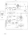
- FIG. 2 a detailed diagram of channel interface component 30 is shown. Further, FIG. 2 shows a programmable channel control logic 80 that is coupled to channel interface component 30 and is configured to perform modulation and demodulation of HART protocol signals for communications with HART device.
- channel interface component 30 includes a suicide relay switch 35 that is configured to connect or disconnect the HART channel 100 from HART device.
- a suicide relay switch 35 that is configured to connect or disconnect the HART channel 100 from HART device.
- Suicide relay switch 35 is controlled by programmable channel control logic 80 and, according to the instructions of programmable channel control logic 80, closes or opens contacts 37, 39. If contacts 37, 39 are closed, then HART channel 100 is connected to HART device (i.e., HART channel 100 is considered the "master”). If contacts 37, 39 are open, then HART channel 100 is disconnected from HART device (i.e., HART channel 100 is considered the "slave”). This suicide relay switch 35 provides the redundancy of HART channel 100. If there is a fault along HART channel 100 (i.e., the "master"), programmable channel control logic 80 may send instructions for suicide relay switch 35 to disconnect HART channel 100 from HART device. Further, programmable channel control logic 80 may send instructions for suicide relay switch 35 to connect HART channel 200 to HART device (i.e., the new "master').
- channel interface component 30 includes a loop voltage supply 40 that is configured to provide a voltage to HART device through terminals 105, 110.
- Programmable channel control logic 80 may specify a digital current setting that is converted to an analog current setting via a digital-to-analog converter (DAC) 42.
- the analog current setting (DCCMD) is provided to the loop voltage supply 40 to provide the voltage to HART device.
- channel interface component 30 may include an analog-to-digital converter (ADC) 44 that digitally represents a measured current from the sensor.
- the ADC 44 provides the measured current (“DCSENSE") to programmable channel control logic 80.
- a voltage modulator 50 is provided for modulating the voltage across terminals 105, 110.
- voltage modulator 50 may include a transformer and a transmit driver connected in series (not shown) or may include any other known circuit form.
- Channel interface component 30 also includes a current regulator 55. However, in the case of HART device including a sensor, the sensor will measure a current for the current loop (not shown).
- programmable channel control logic 80 will send instructions (“MACMD”), through DAC 57, to "short” or “saturate” current regulator 55.
- HART device as a sensor, is sent tones by modulating the voltage across terminals 105, 110 by voltage modulator 50.
- the sensor responds by modulating the measured current via a current resistor 56 and ADC 59.
- current regulator 55 as set to saturate by programmable channel control logic 80, allows the current to pass through.
- HART device In the case that HART device is an actuator, a current must be set for the current loop (not shown) in order to control the actuator.
- Programmable channel control logic 80 will send a digital current setting instructions (“MACMD"), through DAC 57, to current regulator 55 to set a specified DC current for the current loop (not shown).
- MACMD digital current setting instructions
- ADC 45 is provided to receive a response voltage (“DCLEVEL”) from the actuator.
- channel interface component 30 further includes a switch 49 to select the response signal, which is then passed to a filter 46 to extract HART tones from the measured current and provides the HART tones to a modem 48 and to programmable channel control logic 80.
- modem 48 is shown within channel interface component 30, it is understood that modem 48 may be included within programmable channel control logic 80.
- Channel interface component 30 also includes an isolation barrier 60 configured to isolate channel interface component 30 from programmable channel control logic 80. Isolation barrier 60 also isolates all other circuitry following through to terminals 105, 110. This allows for galvanic isolation of each channel 30 for electrical safety and isolation.
- system 10 will be described as including a first HART channel 100 and a second HART channel 200, it is understood that system 10 may include any number of HART channels as the environment requires. Further, it is understood that these operations occur separately within each channel 100, 200, such that channel 100 may be interacting with channel 200. Additionally, channel 100 and channel 200 may be on separate hardware components and each include a separate programmable control logic 80, such that system 10 is interacting with multiple devices.
- programmable channel control logic 80 instructs suicide relay switch 35 of channel interface component 30 to close contacts 37, 39 to connect HART channel 100, by terminals 105, 110, to HART device. HART channel 100 is now the "master”. If “yes”, for example, with HART channel 200, programmable channel control logic 80 instructs suicide relay switch 35 of channel interface component 30 to leave contacts 37, 39 open so that HART channel 200 is disconnected from HART device and HART channel 100 is now the "slave”.
- HART channel 100 is continually checked to determine if HART channel 100 is running properly. If "no", at process P4, a changeover message is sent to HART channel 200 (i.e., the "slave” channel). At process P5, the changeover message is received by HART channel 200.
- programmable channel control logic 80 will instruct suicide relay switch 35 of HART channel 100 (i.e., the "master” channel) to open contacts 37, 39 to disconnect HART channel 100 from HART device, and also instruct suicide relay switch 35 of HART channel 200 (i.e., the "slave” channel) to close contacts 37, 39 to connect HART channel 200 to HART device. In this way, HART channel 200 becomes the "master” channel and HART channel 100 can be replaced and become the "slave” channel.
Landscapes
- Physics & Mathematics (AREA)
- General Physics & Mathematics (AREA)
- Engineering & Computer Science (AREA)
- Automation & Control Theory (AREA)
- Programmable Controllers (AREA)
- Communication Control (AREA)
Description
- The subject matter disclosed herein relates generally to a component within a control system. More particularly, the present disclosure related to a channel interface component including redundancy within a control system with highway addressable remote transfer (HART) channels.
- A HART device is generally a sensor or an actuator that may be used, for example, to control or monitor a system, such as a steam turbine or a gas turbine. The HART device facilitates communication within the control system using the well-known HART protocol. A HART sensor device controls current flowing in a wire, while a HART actuator device is controlled by the current flowing in the wire. In accordance with HART protocol, these functions are performed over the current loop carrying a 4 to 20 milliampere (mA) signal that is superimposed with HART data tones.
- HART devices are interfaced to the control system along a HART channel using modules that perform current loop measurements and current loop driving. However, if a fault occurs along the HART channel, then communication between the HART device and the control system will be interrupted in order to repair the channel and control of the HART device is delayed.
-
EP 2166708 describes a method to communicatively couple field devices to controllers in a process control system comprising decoupling from the first field device a first removable communication module configured to communicate using a first communication protocol and coupling to the first field device a second removable communication module configured to communicate using a second communication protocol. After coupling the second removable communication module, the first field device is configured to communicate using the second communication protocol. The first field device is coupled to a first communication channel on an input/output card when communicating using the first communication protocol and the first field device is coupled to the first communication channel on the input/output card when communicating using the second communication protocol. - Aspects of the invention provide for a HART channel interface component including redundancy. The present invention resides in a circuit as defined in the appended claims.
- These and other features of this invention will be more readily understood from the following detailed description of the various aspects of the invention taken in conjunction with the accompanying drawings that depict various embodiments of the invention, in which:
-
FIG. 1 shows a schematic diagram of a system according to embodiments of the invention. -
FIG. 2 shows a detailed schematic diagram of a channel interface component according to embodiments of the invention. -
FIG. 3 shows a flow diagram of an operational methodology for a system according to embodiments of the invention. - It is noted that the drawings of the invention are not to scale. The drawings are intended to depict only typical aspects of the invention, and therefore should not be considered as limiting the scope of the invention. In the drawings, like numbering represents like elements between the drawings.
- Various embodiments of the present invention are directed to a highway addressable remote transfer (HART) channel interface component that supports HART protocol signals for use in controlling and/monitoring a HART device. In these embodiments, each HART channel interface component includes a suicide relay switch to connect or disconnect the HART channel interface from the HART device. Technical effects associated with the various embodiments of the present invention allow for redundancy of the HART channel interface component and for uninterrupted communication between a control system and the HART device.
- Referring now to the drawings,
FIG. 1 shows a schematic diagram of asystem 10 including acontrol system 15 in communication, through acontrol network 20, with a HART device over a first highway addressable remote transfer (HART)channel 100 or asecond HART channel 200. Eachchannel input terminal output terminal FIG. 2 , eachchannel channel interface component 30 that is configured to connect or disconnectfirst HART channel 100 orsecond HART channel 200 from HART device. - In one embodiment, HART device may be a sensor or an actuator that is used in the control of a turbine. HART device is embedded with the "smarts" to facilitate communication with each channel interface component 30 (
FIG. 2 ) using the well-known HART protocol. - Although
system 10 ofFIG. 1 is described with respect to use in the control of a turbine, those skilled in the art will recognize that the various embodiments of the present invention are not limited to use solely with monitoring and/or controlling a turbine. The various embodiments of the present invention have a diverse range of applications that are suitable for any environment that includes HART devices. Further, althoughsystem 10 ofFIG. 1 is shown to includefirst HART channel 100 andsecond HART channel 200, it is understood thatsystem 10 may include any number of channels as necessary for the environment of HART device. - Referring now to
FIG. 2 , a detailed diagram ofchannel interface component 30 is shown. Further,FIG. 2 shows a programmablechannel control logic 80 that is coupled tochannel interface component 30 and is configured to perform modulation and demodulation of HART protocol signals for communications with HART device. - As shown in
FIG. 2 ,channel interface component 30 includes asuicide relay switch 35 that is configured to connect or disconnect theHART channel 100 from HART device. Althoughchannel interface component 30 is described with respect toHART channel 100, it is understood thatHART channel 200 includes the samechannel interface component 30. -
Suicide relay switch 35 is controlled by programmablechannel control logic 80 and, according to the instructions of programmablechannel control logic 80, closes or openscontacts contacts channel 100 is connected to HART device (i.e., HARTchannel 100 is considered the "master"). Ifcontacts channel 100 is disconnected from HART device (i.e., HARTchannel 100 is considered the "slave"). Thissuicide relay switch 35 provides the redundancy ofHART channel 100. If there is a fault along HART channel 100 (i.e., the "master"), programmablechannel control logic 80 may send instructions forsuicide relay switch 35 to disconnectHART channel 100 from HART device. Further, programmablechannel control logic 80 may send instructions forsuicide relay switch 35 to connect HARTchannel 200 to HART device (i.e., the new "master'). - Referring back to
FIG. 2 ,channel interface component 30 includes aloop voltage supply 40 that is configured to provide a voltage to HART device throughterminals channel control logic 80 may specify a digital current setting that is converted to an analog current setting via a digital-to-analog converter (DAC) 42. The analog current setting (DCCMD) is provided to theloop voltage supply 40 to provide the voltage to HART device. - In the case that HART device includes a sensor,
channel interface component 30 may include an analog-to-digital converter (ADC) 44 that digitally represents a measured current from the sensor. The ADC 44 provides the measured current ("DCSENSE") to programmablechannel control logic 80. Avoltage modulator 50 is provided for modulating the voltage acrossterminals voltage modulator 50 may include a transformer and a transmit driver connected in series (not shown) or may include any other known circuit form.Channel interface component 30 also includes a current regulator 55. However, in the case of HART device including a sensor, the sensor will measure a current for the current loop (not shown). In this case, programmablechannel control logic 80 will send instructions ("MACMD"), throughDAC 57, to "short" or "saturate" current regulator 55. HART device, as a sensor, is sent tones by modulating the voltage acrossterminals voltage modulator 50. The sensor responds by modulating the measured current via a current resistor 56 and ADC 59. In this way current regulator 55, as set to saturate by programmablechannel control logic 80, allows the current to pass through. - In the case that HART device is an actuator, a current must be set for the current loop (not shown) in order to control the actuator. Programmable
channel control logic 80 will send a digital current setting instructions ("MACMD"), throughDAC 57, to current regulator 55 to set a specified DC current for the current loop (not shown). If HART device is an actuator,voltage modulator 50 is set, by programmablechannel control logic 80 to a steady state low voltage. Further, ADC 45 is provided to receive a response voltage ("DCLEVEL") from the actuator. - In either case of a sensor or an actuator for HART device,
channel interface component 30 further includes a switch 49 to select the response signal, which is then passed to afilter 46 to extract HART tones from the measured current and provides the HART tones to amodem 48 and to programmablechannel control logic 80. Althoughmodem 48 is shown withinchannel interface component 30, it is understood thatmodem 48 may be included within programmablechannel control logic 80.Channel interface component 30 also includes anisolation barrier 60 configured to isolatechannel interface component 30 from programmablechannel control logic 80.Isolation barrier 60 also isolates all other circuitry following through toterminals channel 30 for electrical safety and isolation. - Turning now to
FIG. 3 , an operational embodiment ofsystem 10 will now be described with references toFIGS. 1 and2 . Althoughsystem 10 will be described as including afirst HART channel 100 and asecond HART channel 200, it is understood thatsystem 10 may include any number of HART channels as the environment requires. Further, it is understood that these operations occur separately within eachchannel channel 100 may be interacting withchannel 200. Additionally,channel 100 andchannel 200 may be on separate hardware components and each include a separateprogrammable control logic 80, such thatsystem 10 is interacting with multiple devices. - At process P1, whether a failed unit is being replaced is determined. If "no", for example, with
HART channel 100, programmablechannel control logic 80 instructssuicide relay switch 35 ofchannel interface component 30 to closecontacts HART channel 100, byterminals HART channel 100 is now the "master". If "yes", for example, withHART channel 200, programmablechannel control logic 80 instructssuicide relay switch 35 ofchannel interface component 30 to leavecontacts HART channel 200 is disconnected from HART device andHART channel 100 is now the "slave". - Following along with the example of
HART channel 100 as the "master" channel, at process P3,HART channel 100 is continually checked to determine ifHART channel 100 is running properly. If "no", at process P4, a changeover message is sent to HART channel 200 (i.e., the "slave" channel). At process P5, the changeover message is received byHART channel 200. At process P6 and P7, programmablechannel control logic 80 will instructsuicide relay switch 35 of HART channel 100 (i.e., the "master" channel) to opencontacts HART channel 100 from HART device, and also instructsuicide relay switch 35 of HART channel 200 (i.e., the "slave" channel) to closecontacts HART channel 200 to HART device. In this way,HART channel 200 becomes the "master" channel andHART channel 100 can be replaced and become the "slave" channel. - The terminology used herein is for the purpose of describing particular embodiments only and is not intended to be limiting of the invention. As used herein, the singular forms "a", "an" and "the" are intended to include the plural forms as well, unless the context clearly indicates otherwise. It will be further understood that the terms "comprises" and/or "comprising," when used in this specification, specify the presence of stated features, integers, steps, operations, elements, and/or components, but do not preclude the presence or addition of one or more other features, integers, steps, operations, elements, components, and/or groups thereof.
- This written description uses examples to disclose the invention, including the best mode, and also to enable any person skilled in the art to practice the invention, including making and using any devices or systems and performing any incorporated methods. The patentable scope of the invention is defined by the claims, and may include other examples that occur to those skilled in the art. Such other examples are intended to be within the scope of the claims if they have structural elements that do not differ from the literal language of the claims, or if they include equivalent structural elements with insubstantial differences from the literal languages of the claims.
Claims (6)
- A circuit for providing redundant highway addressable remote transfer (HART) channels, comprising: a redundant pair of channel interface components (30), each having an input terminal (105, 205) and an output terminal (110, 210) configured to connect with a common HART device, wherein each channel interface component (30) includes circuitry for implementing a current loop with the common HART device to operate in a range of 4 to 20 milliamperes; and
a programmable logic device (80) coupled to a suicide relay switch (35) in each channel interface component (30) for alternatively activating and deactivating the redundant pair of channel interface components (30) by connecting and disconnecting respective current loops to provide a master channel and a slave channel, wherein the programmable logic device is programmable to operate the redundant pair of channel interface components to receive HART protocol current signals from a sensor or send HART protocol current signals to an actuator;
wherein each channel interface component includes:a loop voltage supply (40) for powering the current loop, wherein the loop voltage is controlled by a digital signal from the programmable logic device that is passed through a digital to analog converter, DAC;a voltage modulator (50) and a current regulator (55) arranged in series with a ground, wherein the voltage modulator (50) provides tones by modulating the voltage across the terminals while operating the redundant pair of channel interface components to receive HART protocol current signals from a sensor, and the current regulator provides a currentspecified from the programmable logic device onto the current loop while operating the redundant pair of channel interface components to send HART protocol current signals to an actuator. andan isolation barrier that isolates the channel interface component from the programmable logic device. - The circuit according to claim 1, wherein each channel interface component (30) includes a first switchable contact (37) coupled between the loop voltage supply and the output terminal and a second switchable contact (39) coupled between the input terminal and the current regulator.
- The circuit according to claim 2, wherein the first and second switchable contacts are controllable in tandem by the suicide relay switch to activate and deactivate the channel interface components (30).
- The circuit according to claim 1, wherein the current regulator in each channel interface component (30) is controlled by a signal from the programmable logic device via a second DAC (57), wherein the signal saturates the current regulator while operating the redundant pair of channel interface components to receive HART protocol current signals from a sensor and sets a current for the current loop while operating to send HART protocol current signals to an actuator.
- The circuit according to claim 1, further comprising a resistor (Rsense) coupled in series between the voltage modulator and current regulator to capture a sensor response while operating the redundant pair of channel interface components to receive HART protocol current signals from a sensor.
- The circuit according to claim 5, further comprising:a filter for extracting HART tones from the sensor response; anda modem for processing the HART tones.
Applications Claiming Priority (1)
| Application Number | Priority Date | Filing Date | Title |
|---|---|---|---|
| US13/074,781 US20120253481A1 (en) | 2011-03-29 | 2011-03-29 | Hart channel interface component including redundancy |
Publications (3)
| Publication Number | Publication Date |
|---|---|
| EP2506101A2 EP2506101A2 (en) | 2012-10-03 |
| EP2506101A3 EP2506101A3 (en) | 2014-05-07 |
| EP2506101B1 true EP2506101B1 (en) | 2018-01-10 |
Family
ID=45952896
Family Applications (1)
| Application Number | Title | Priority Date | Filing Date |
|---|---|---|---|
| EP12161430.9A Active EP2506101B1 (en) | 2011-03-29 | 2012-03-27 | Hart channel interface component including redundancy |
Country Status (4)
| Country | Link |
|---|---|
| US (2) | US20120253481A1 (en) |
| EP (1) | EP2506101B1 (en) |
| CN (1) | CN102736513A (en) |
| IN (1) | IN2012DE00782A (en) |
Cited By (1)
| Publication number | Priority date | Publication date | Assignee | Title |
|---|---|---|---|---|
| DE102018204596A1 (en) | 2018-03-27 | 2019-10-02 | Robert Bosch Gmbh | sensor arrangement |
Families Citing this family (11)
| Publication number | Priority date | Publication date | Assignee | Title |
|---|---|---|---|---|
| JP5784284B2 (en) * | 2010-06-30 | 2015-09-24 | アズビル株式会社 | Input/output device with HART communication function |
| DE102011085877B4 (en) * | 2011-11-07 | 2016-03-17 | Siemens Aktiengesellschaft | Communication method and communication device for the process industry |
| CN104022771A (en) * | 2013-03-01 | 2014-09-03 | 德律科技股份有限公司 | Test equipment with reverse drive protection function |
| TWI523420B (en) * | 2013-03-01 | 2016-02-21 | 德律科技股份有限公司 | Testing apparatus with backdriving protection function |
| EP2832071A4 (en) * | 2013-03-19 | 2015-11-18 | Gen Electric | Current loop voltage modulator for communication interface |
| US9008197B2 (en) * | 2013-07-26 | 2015-04-14 | General Electric Company | Current loop voltage modulator for communication interface |
| WO2016089384A1 (en) | 2014-12-03 | 2016-06-09 | General Electric Company | Universal input and output interface |
| DE102015105887A1 (en) * | 2015-04-17 | 2016-10-20 | Endress + Hauser Process Solutions Ag | Method for automatically adding or removing a communication resistor of a HART device |
| US11729272B2 (en) * | 2020-09-25 | 2023-08-15 | Texas Instruments Incorporated | Hart-enabled device with reduced communication lines and break extension protocol |
| CN113885391B (en) * | 2021-10-18 | 2023-05-16 | 西安微电子技术研究所 | Dual-redundancy steering engine switching instruction interface circuit and instruction switching method |
| CN115379023A (en) * | 2022-08-25 | 2022-11-22 | 国核自仪系统工程有限公司 | HART communication device |
Family Cites Families (20)
| Publication number | Priority date | Publication date | Assignee | Title |
|---|---|---|---|---|
| US4872120A (en) * | 1984-12-20 | 1989-10-03 | Gull Inc. | Multiplexed junction probe for fuel gaging system and system containing same |
| CA2203561C (en) * | 1994-10-24 | 2004-09-21 | Thomas Andrew Boyd | Apparatus for providing access to field devices in a distributed control system |
| TR199800710T2 (en) * | 1995-10-31 | 1998-08-21 | Pfizer Inc. | Process and intermediates for the preparation of 1-(2(2-isoxazol-3-ylbenzofuran-5-yloxy)ethylamino)-3-phenoxy-2(S)-ol. |
| US5982595A (en) * | 1998-06-05 | 1999-11-09 | General Electric Company | Redundant communications in a protective relay |
| US7844365B2 (en) * | 2000-05-12 | 2010-11-30 | Rosemount Inc. | Field-mounted process device |
| US7372914B2 (en) * | 2000-11-16 | 2008-05-13 | Invensys Systems, Inc. | Control system methods and apparatus for inductive communication across an isolation barrier |
| US6540812B2 (en) * | 2001-07-06 | 2003-04-01 | Bha Group Holdings, Inc. | Method and system for improved rapper control |
| US6959356B2 (en) * | 2001-07-30 | 2005-10-25 | Fisher-Rosemount Systems, Inc. | Multi-protocol field device and communication method |
| EP1433030A2 (en) * | 2001-07-31 | 2004-06-30 | Endress + Hauser GmbH + Co. KG | Supervisory control and data acquisition interface for tank or process monitor |
| CA2406298A1 (en) * | 2002-09-30 | 2004-03-30 | Siemens Milltronics Process Instruments Inc. | Power management mechanism for loop powered time of flight and level measurement systems |
| US7460865B2 (en) * | 2003-06-18 | 2008-12-02 | Fisher-Rosemount Systems, Inc. | Self-configuring communication networks for use with process control systems |
| CN2640135Y (en) * | 2003-09-11 | 2004-09-08 | 北京华控技术有限责任公司 | Network interconnection unit for connecting high-speed Ethernet and HART bus |
| US7793137B2 (en) * | 2004-10-07 | 2010-09-07 | Cisco Technology, Inc. | Redundant power and data in a wired data telecommunincations network |
| DE102005057122A1 (en) * | 2005-11-30 | 2007-05-31 | Siemens Ag | Ethernet network, has switches which are formed in network start-up phase by distribution of special telegrams to configure active and inactive coupling channels in distortion free operation |
| EP1819028B1 (en) * | 2006-02-08 | 2012-12-05 | Moore Industries International Inc. | Redundant fieldbus system |
| JP4507125B2 (en) * | 2007-09-10 | 2010-07-21 | 三菱電機株式会社 | Programmable controller |
| US9083548B2 (en) * | 2008-09-23 | 2015-07-14 | Fisher-Rosemount Systems, Inc. | Apparatus and methods to communicatively couple field devices to controllers in a process control system |
| CN201509197U (en) * | 2009-07-13 | 2010-06-16 | 厦门胜华通信技术有限公司 | Standby channel switching control device |
| EP2771975A4 (en) * | 2010-03-18 | 2018-03-21 | Mactek Corporation | Frequency shift keying modulation and demodulation |
| US9735570B2 (en) * | 2010-03-24 | 2017-08-15 | Pepperl + Fuchs Gmbh | Power management circuit for wireless communication device and process control system using same |
-
2011
- 2011-03-29 US US13/074,781 patent/US20120253481A1/en not_active Abandoned
-
2012
- 2012-03-16 IN IN782DE2012 patent/IN2012DE00782A/en unknown
- 2012-03-27 EP EP12161430.9A patent/EP2506101B1/en active Active
- 2012-03-29 CN CN2012100996009A patent/CN102736513A/en active Pending
-
2014
- 2014-12-16 US US14/571,825 patent/US20150100137A1/en not_active Abandoned
Non-Patent Citations (1)
| Title |
|---|
| None * |
Cited By (1)
| Publication number | Priority date | Publication date | Assignee | Title |
|---|---|---|---|---|
| DE102018204596A1 (en) | 2018-03-27 | 2019-10-02 | Robert Bosch Gmbh | sensor arrangement |
Also Published As
| Publication number | Publication date |
|---|---|
| CN102736513A (en) | 2012-10-17 |
| US20150100137A1 (en) | 2015-04-09 |
| US20120253481A1 (en) | 2012-10-04 |
| EP2506101A2 (en) | 2012-10-03 |
| EP2506101A3 (en) | 2014-05-07 |
| IN2012DE00782A (en) | 2015-08-21 |
Similar Documents
| Publication | Publication Date | Title |
|---|---|---|
| EP2506101A2 (en) | Hart channel interface component including redundancy | |
| KR101341683B1 (en) | Protection and control system for electric power networks with signal and command interfaces at the primary equipment | |
| EP3001535B1 (en) | Protection control system for process bus, merging unit, and computation device | |
| US9946613B2 (en) | Instrumentation system and method for maintaining the same | |
| US7675200B2 (en) | Combination control system with intermediate module | |
| JP2014146363A (en) | Emergency shutdown system | |
| CN102092351A (en) | Embedded wireless communications for electronic control unit having multiple ground references | |
| CN101262128A (en) | Temperature release device | |
| US7755872B2 (en) | System, method and device to preserve protection communication active during a bypass operation | |
| US11981408B2 (en) | Method and device for data transmission on board a watercraft | |
| CN114371355A (en) | Self-adaptive joint debugging system for realizing multi-interval point-to-point test of distribution automation terminal | |
| JP2004010200A (en) | Signal switching method for elevator | |
| RU2570572C1 (en) | Microprocessor control panel | |
| CN104025407A (en) | Integration Unit And Protection Relay System | |
| CN109888749B (en) | A DC circuit breaker control method and device | |
| US20210109157A1 (en) | Multiple merging unit testing system | |
| JP4717729B2 (en) | Supervisory control device | |
| EP3758241B1 (en) | Submarine cable system, branching device, and state response method therefor | |
| JP4670810B2 (en) | Power line carrier communication system and signal relay device | |
| KR101403608B1 (en) | Interlock control system and controlling method thereof | |
| CN114743830A (en) | Signal switching circuit, method and system based on relay logic | |
| JP3165069B2 (en) | Fieldbus systems and virtual field devices | |
| JP2012080673A (en) | Failsafe apparatus for performing parallel-off of isolated system | |
| JPH03243144A (en) | Automatic recovery unit | |
| HK1127685A (en) | Arrangement with a field device and converter device and method for operating them |
Legal Events
| Date | Code | Title | Description |
|---|---|---|---|
| PUAI | Public reference made under article 153(3) epc to a published international application that has entered the european phase |
Free format text: ORIGINAL CODE: 0009012 |
|
| AK | Designated contracting states |
Kind code of ref document: A2 Designated state(s): AL AT BE BG CH CY CZ DE DK EE ES FI FR GB GR HR HU IE IS IT LI LT LU LV MC MK MT NL NO PL PT RO RS SE SI SK SM TR |
|
| AX | Request for extension of the european patent |
Extension state: BA ME |
|
| PUAL | Search report despatched |
Free format text: ORIGINAL CODE: 0009013 |
|
| AK | Designated contracting states |
Kind code of ref document: A3 Designated state(s): AL AT BE BG CH CY CZ DE DK EE ES FI FR GB GR HR HU IE IS IT LI LT LU LV MC MK MT NL NO PL PT RO RS SE SI SK SM TR |
|
| AX | Request for extension of the european patent |
Extension state: BA ME |
|
| RIC1 | Information provided on ipc code assigned before grant |
Ipc: G05B 19/042 20060101AFI20140331BHEP |
|
| 17P | Request for examination filed |
Effective date: 20141107 |
|
| RBV | Designated contracting states (corrected) |
Designated state(s): AL AT BE BG CH CY CZ DE DK EE ES FI FR GB GR HR HU IE IS IT LI LT LU LV MC MK MT NL NO PL PT RO RS SE SI SK SM TR |
|
| 17Q | First examination report despatched |
Effective date: 20160218 |
|
| GRAP | Despatch of communication of intention to grant a patent |
Free format text: ORIGINAL CODE: EPIDOSNIGR1 |
|
| RIC1 | Information provided on ipc code assigned before grant |
Ipc: G05B 19/042 20060101AFI20170801BHEP Ipc: G05B 9/03 20060101ALI20170801BHEP |
|
| INTG | Intention to grant announced |
Effective date: 20170901 |
|
| GRAS | Grant fee paid |
Free format text: ORIGINAL CODE: EPIDOSNIGR3 |
|
| GRAA | (expected) grant |
Free format text: ORIGINAL CODE: 0009210 |
|
| AK | Designated contracting states |
Kind code of ref document: B1 Designated state(s): AL AT BE BG CH CY CZ DE DK EE ES FI FR GB GR HR HU IE IS IT LI LT LU LV MC MK MT NL NO PL PT RO RS SE SI SK SM TR |
|
| REG | Reference to a national code |
Ref country code: GB Ref legal event code: FG4D |
|
| REG | Reference to a national code |
Ref country code: CH Ref legal event code: EP Ref country code: AT Ref legal event code: REF Ref document number: 963053 Country of ref document: AT Kind code of ref document: T Effective date: 20180115 |
|
| REG | Reference to a national code |
Ref country code: IE Ref legal event code: FG4D |
|
| REG | Reference to a national code |
Ref country code: DE Ref legal event code: R096 Ref document number: 602012041755 Country of ref document: DE |
|
| REG | Reference to a national code |
Ref country code: FR Ref legal event code: PLFP Year of fee payment: 7 |
|
| REG | Reference to a national code |
Ref country code: NL Ref legal event code: MP Effective date: 20180110 |
|
| REG | Reference to a national code |
Ref country code: AT Ref legal event code: MK05 Ref document number: 963053 Country of ref document: AT Kind code of ref document: T Effective date: 20180110 |
|
| PG25 | Lapsed in a contracting state [announced via postgrant information from national office to epo] |
Ref country code: NL Free format text: LAPSE BECAUSE OF FAILURE TO SUBMIT A TRANSLATION OF THE DESCRIPTION OR TO PAY THE FEE WITHIN THE PRESCRIBED TIME-LIMIT Effective date: 20180110 |
|
| PG25 | Lapsed in a contracting state [announced via postgrant information from national office to epo] |
Ref country code: ES Free format text: LAPSE BECAUSE OF FAILURE TO SUBMIT A TRANSLATION OF THE DESCRIPTION OR TO PAY THE FEE WITHIN THE PRESCRIBED TIME-LIMIT Effective date: 20180110 Ref country code: CY Free format text: LAPSE BECAUSE OF FAILURE TO SUBMIT A TRANSLATION OF THE DESCRIPTION OR TO PAY THE FEE WITHIN THE PRESCRIBED TIME-LIMIT Effective date: 20180110 Ref country code: FI Free format text: LAPSE BECAUSE OF FAILURE TO SUBMIT A TRANSLATION OF THE DESCRIPTION OR TO PAY THE FEE WITHIN THE PRESCRIBED TIME-LIMIT Effective date: 20180110 Ref country code: LT Free format text: LAPSE BECAUSE OF FAILURE TO SUBMIT A TRANSLATION OF THE DESCRIPTION OR TO PAY THE FEE WITHIN THE PRESCRIBED TIME-LIMIT Effective date: 20180110 Ref country code: HR Free format text: LAPSE BECAUSE OF FAILURE TO SUBMIT A TRANSLATION OF THE DESCRIPTION OR TO PAY THE FEE WITHIN THE PRESCRIBED TIME-LIMIT Effective date: 20180110 Ref country code: NO Free format text: LAPSE BECAUSE OF FAILURE TO SUBMIT A TRANSLATION OF THE DESCRIPTION OR TO PAY THE FEE WITHIN THE PRESCRIBED TIME-LIMIT Effective date: 20180410 |
|
| PG25 | Lapsed in a contracting state [announced via postgrant information from national office to epo] |
Ref country code: AT Free format text: LAPSE BECAUSE OF FAILURE TO SUBMIT A TRANSLATION OF THE DESCRIPTION OR TO PAY THE FEE WITHIN THE PRESCRIBED TIME-LIMIT Effective date: 20180110 Ref country code: GR Free format text: LAPSE BECAUSE OF FAILURE TO SUBMIT A TRANSLATION OF THE DESCRIPTION OR TO PAY THE FEE WITHIN THE PRESCRIBED TIME-LIMIT Effective date: 20180411 Ref country code: BG Free format text: LAPSE BECAUSE OF FAILURE TO SUBMIT A TRANSLATION OF THE DESCRIPTION OR TO PAY THE FEE WITHIN THE PRESCRIBED TIME-LIMIT Effective date: 20180410 Ref country code: RS Free format text: LAPSE BECAUSE OF FAILURE TO SUBMIT A TRANSLATION OF THE DESCRIPTION OR TO PAY THE FEE WITHIN THE PRESCRIBED TIME-LIMIT Effective date: 20180110 Ref country code: IS Free format text: LAPSE BECAUSE OF FAILURE TO SUBMIT A TRANSLATION OF THE DESCRIPTION OR TO PAY THE FEE WITHIN THE PRESCRIBED TIME-LIMIT Effective date: 20180510 Ref country code: SE Free format text: LAPSE BECAUSE OF FAILURE TO SUBMIT A TRANSLATION OF THE DESCRIPTION OR TO PAY THE FEE WITHIN THE PRESCRIBED TIME-LIMIT Effective date: 20180110 Ref country code: PL Free format text: LAPSE BECAUSE OF FAILURE TO SUBMIT A TRANSLATION OF THE DESCRIPTION OR TO PAY THE FEE WITHIN THE PRESCRIBED TIME-LIMIT Effective date: 20180110 Ref country code: LV Free format text: LAPSE BECAUSE OF FAILURE TO SUBMIT A TRANSLATION OF THE DESCRIPTION OR TO PAY THE FEE WITHIN THE PRESCRIBED TIME-LIMIT Effective date: 20180110 |
|
| REG | Reference to a national code |
Ref country code: DE Ref legal event code: R097 Ref document number: 602012041755 Country of ref document: DE |
|
| PG25 | Lapsed in a contracting state [announced via postgrant information from national office to epo] |
Ref country code: IT Free format text: LAPSE BECAUSE OF FAILURE TO SUBMIT A TRANSLATION OF THE DESCRIPTION OR TO PAY THE FEE WITHIN THE PRESCRIBED TIME-LIMIT Effective date: 20180110 Ref country code: RO Free format text: LAPSE BECAUSE OF FAILURE TO SUBMIT A TRANSLATION OF THE DESCRIPTION OR TO PAY THE FEE WITHIN THE PRESCRIBED TIME-LIMIT Effective date: 20180110 Ref country code: EE Free format text: LAPSE BECAUSE OF FAILURE TO SUBMIT A TRANSLATION OF THE DESCRIPTION OR TO PAY THE FEE WITHIN THE PRESCRIBED TIME-LIMIT Effective date: 20180110 Ref country code: AL Free format text: LAPSE BECAUSE OF FAILURE TO SUBMIT A TRANSLATION OF THE DESCRIPTION OR TO PAY THE FEE WITHIN THE PRESCRIBED TIME-LIMIT Effective date: 20180110 |
|
| REG | Reference to a national code |
Ref country code: CH Ref legal event code: PL |
|
| PLBE | No opposition filed within time limit |
Free format text: ORIGINAL CODE: 0009261 |
|
| STAA | Information on the status of an ep patent application or granted ep patent |
Free format text: STATUS: NO OPPOSITION FILED WITHIN TIME LIMIT |
|
| PG25 | Lapsed in a contracting state [announced via postgrant information from national office to epo] |
Ref country code: SM Free format text: LAPSE BECAUSE OF FAILURE TO SUBMIT A TRANSLATION OF THE DESCRIPTION OR TO PAY THE FEE WITHIN THE PRESCRIBED TIME-LIMIT Effective date: 20180110 Ref country code: SK Free format text: LAPSE BECAUSE OF FAILURE TO SUBMIT A TRANSLATION OF THE DESCRIPTION OR TO PAY THE FEE WITHIN THE PRESCRIBED TIME-LIMIT Effective date: 20180110 Ref country code: DK Free format text: LAPSE BECAUSE OF FAILURE TO SUBMIT A TRANSLATION OF THE DESCRIPTION OR TO PAY THE FEE WITHIN THE PRESCRIBED TIME-LIMIT Effective date: 20180110 Ref country code: CZ Free format text: LAPSE BECAUSE OF FAILURE TO SUBMIT A TRANSLATION OF THE DESCRIPTION OR TO PAY THE FEE WITHIN THE PRESCRIBED TIME-LIMIT Effective date: 20180110 Ref country code: MC Free format text: LAPSE BECAUSE OF FAILURE TO SUBMIT A TRANSLATION OF THE DESCRIPTION OR TO PAY THE FEE WITHIN THE PRESCRIBED TIME-LIMIT Effective date: 20180110 |
|
| REG | Reference to a national code |
Ref country code: BE Ref legal event code: MM Effective date: 20180331 |
|
| 26N | No opposition filed |
Effective date: 20181011 |
|
| REG | Reference to a national code |
Ref country code: IE Ref legal event code: MM4A |
|
| PG25 | Lapsed in a contracting state [announced via postgrant information from national office to epo] |
Ref country code: LU Free format text: LAPSE BECAUSE OF NON-PAYMENT OF DUE FEES Effective date: 20180327 |
|
| PG25 | Lapsed in a contracting state [announced via postgrant information from national office to epo] |
Ref country code: IE Free format text: LAPSE BECAUSE OF NON-PAYMENT OF DUE FEES Effective date: 20180327 |
|
| PG25 | Lapsed in a contracting state [announced via postgrant information from national office to epo] |
Ref country code: SI Free format text: LAPSE BECAUSE OF FAILURE TO SUBMIT A TRANSLATION OF THE DESCRIPTION OR TO PAY THE FEE WITHIN THE PRESCRIBED TIME-LIMIT Effective date: 20180110 Ref country code: BE Free format text: LAPSE BECAUSE OF NON-PAYMENT OF DUE FEES Effective date: 20180331 Ref country code: LI Free format text: LAPSE BECAUSE OF NON-PAYMENT OF DUE FEES Effective date: 20180331 Ref country code: CH Free format text: LAPSE BECAUSE OF NON-PAYMENT OF DUE FEES Effective date: 20180331 |
|
| PG25 | Lapsed in a contracting state [announced via postgrant information from national office to epo] |
Ref country code: MT Free format text: LAPSE BECAUSE OF NON-PAYMENT OF DUE FEES Effective date: 20180327 |
|
| PG25 | Lapsed in a contracting state [announced via postgrant information from national office to epo] |
Ref country code: TR Free format text: LAPSE BECAUSE OF FAILURE TO SUBMIT A TRANSLATION OF THE DESCRIPTION OR TO PAY THE FEE WITHIN THE PRESCRIBED TIME-LIMIT Effective date: 20180110 |
|
| PG25 | Lapsed in a contracting state [announced via postgrant information from national office to epo] |
Ref country code: PT Free format text: LAPSE BECAUSE OF FAILURE TO SUBMIT A TRANSLATION OF THE DESCRIPTION OR TO PAY THE FEE WITHIN THE PRESCRIBED TIME-LIMIT Effective date: 20180110 Ref country code: HU Free format text: LAPSE BECAUSE OF FAILURE TO SUBMIT A TRANSLATION OF THE DESCRIPTION OR TO PAY THE FEE WITHIN THE PRESCRIBED TIME-LIMIT; INVALID AB INITIO Effective date: 20120327 |
|
| PG25 | Lapsed in a contracting state [announced via postgrant information from national office to epo] |
Ref country code: MK Free format text: LAPSE BECAUSE OF NON-PAYMENT OF DUE FEES Effective date: 20180110 |
|
| REG | Reference to a national code |
Ref country code: DE Ref legal event code: R081 Ref document number: 602012041755 Country of ref document: DE Owner name: GENERAL ELECTRIC TECHNOLOGY GMBH, CH Free format text: FORMER OWNER: GENERAL ELECTRIC COMPANY, SCHENECTADY, NY, US |
|
| REG | Reference to a national code |
Ref country code: GB Ref legal event code: 732E Free format text: REGISTERED BETWEEN 20240222 AND 20240228 |
|
| PGFP | Annual fee paid to national office [announced via postgrant information from national office to epo] |
Ref country code: GB Payment date: 20260220 Year of fee payment: 15 |
|
| PGFP | Annual fee paid to national office [announced via postgrant information from national office to epo] |
Ref country code: DE Payment date: 20260219 Year of fee payment: 15 |
|
| PGFP | Annual fee paid to national office [announced via postgrant information from national office to epo] |
Ref country code: FR Payment date: 20260219 Year of fee payment: 15 |