EP2505921B1 - Kreuzfeuerbrennkammerohr mit Ausblaslöchern - Google Patents
Kreuzfeuerbrennkammerohr mit Ausblaslöchern Download PDFInfo
- Publication number
- EP2505921B1 EP2505921B1 EP12161136.2A EP12161136A EP2505921B1 EP 2505921 B1 EP2505921 B1 EP 2505921B1 EP 12161136 A EP12161136 A EP 12161136A EP 2505921 B1 EP2505921 B1 EP 2505921B1
- Authority
- EP
- European Patent Office
- Prior art keywords
- flow
- combustor
- fuel
- air
- fuel injectors
- Prior art date
- Legal status (The legal status is an assumption and is not a legal conclusion. Google has not performed a legal analysis and makes no representation as to the accuracy of the status listed.)
- Active
Links
- VEMKTZHHVJILDY-UHFFFAOYSA-N resmethrin Chemical compound CC1(C)C(C=C(C)C)C1C(=O)OCC1=COC(CC=2C=CC=CC=2)=C1 VEMKTZHHVJILDY-UHFFFAOYSA-N 0.000 title claims description 40
- 238000010926 purge Methods 0.000 title claims description 28
- 239000000446 fuel Substances 0.000 claims description 55
- 238000011144 upstream manufacturing Methods 0.000 claims description 12
- 238000002485 combustion reaction Methods 0.000 claims description 11
- 238000000034 method Methods 0.000 claims description 5
- 238000002347 injection Methods 0.000 claims description 2
- 239000007924 injection Substances 0.000 claims description 2
- 238000013508 migration Methods 0.000 claims description 2
- 230000005012 migration Effects 0.000 claims description 2
- 239000007789 gas Substances 0.000 description 20
- MWUXSHHQAYIFBG-UHFFFAOYSA-N nitrogen oxide Inorganic materials O=[N] MWUXSHHQAYIFBG-UHFFFAOYSA-N 0.000 description 12
- 239000000567 combustion gas Substances 0.000 description 6
- 238000013461 design Methods 0.000 description 3
- 230000008030 elimination Effects 0.000 description 2
- 238000003379 elimination reaction Methods 0.000 description 2
- 230000006872 improvement Effects 0.000 description 2
- VNWKTOKETHGBQD-UHFFFAOYSA-N methane Chemical compound C VNWKTOKETHGBQD-UHFFFAOYSA-N 0.000 description 2
- 239000000203 mixture Substances 0.000 description 2
- UFHFLCQGNIYNRP-UHFFFAOYSA-N Hydrogen Chemical compound [H][H] UFHFLCQGNIYNRP-UHFFFAOYSA-N 0.000 description 1
- 238000006243 chemical reaction Methods 0.000 description 1
- 230000007797 corrosion Effects 0.000 description 1
- 238000005260 corrosion Methods 0.000 description 1
- 239000001257 hydrogen Substances 0.000 description 1
- 229910052739 hydrogen Inorganic materials 0.000 description 1
- 238000004519 manufacturing process Methods 0.000 description 1
- 238000012986 modification Methods 0.000 description 1
- 230000004048 modification Effects 0.000 description 1
- 239000003345 natural gas Substances 0.000 description 1
- 230000037361 pathway Effects 0.000 description 1
- 230000035515 penetration Effects 0.000 description 1
- 238000010248 power generation Methods 0.000 description 1
- 230000009467 reduction Effects 0.000 description 1
- 230000001105 regulatory effect Effects 0.000 description 1
- 238000012552 review Methods 0.000 description 1
- 238000004513 sizing Methods 0.000 description 1
- 238000012546 transfer Methods 0.000 description 1
Images


Classifications
-
- F—MECHANICAL ENGINEERING; LIGHTING; HEATING; WEAPONS; BLASTING
- F23—COMBUSTION APPARATUS; COMBUSTION PROCESSES
- F23R—GENERATING COMBUSTION PRODUCTS OF HIGH PRESSURE OR HIGH VELOCITY, e.g. GAS-TURBINE COMBUSTION CHAMBERS
- F23R3/00—Continuous combustion chambers using liquid or gaseous fuel
- F23R3/42—Continuous combustion chambers using liquid or gaseous fuel characterised by the arrangement or form of the flame tubes or combustion chambers
- F23R3/46—Combustion chambers comprising an annular arrangement of several essentially tubular flame tubes within a common annular casing or within individual casings
- F23R3/48—Flame tube interconnectors, e.g. cross-over tubes
-
- F—MECHANICAL ENGINEERING; LIGHTING; HEATING; WEAPONS; BLASTING
- F23—COMBUSTION APPARATUS; COMBUSTION PROCESSES
- F23R—GENERATING COMBUSTION PRODUCTS OF HIGH PRESSURE OR HIGH VELOCITY, e.g. GAS-TURBINE COMBUSTION CHAMBERS
- F23R3/00—Continuous combustion chambers using liquid or gaseous fuel
- F23R3/28—Continuous combustion chambers using liquid or gaseous fuel characterised by the fuel supply
- F23R3/286—Continuous combustion chambers using liquid or gaseous fuel characterised by the fuel supply having fuel-air premixing devices
Definitions
- the present application relates generally to gas turbine engines and more particularly relates to gas turbine engine combustors with crossfire tubes having purge holes positioned therein to limit a wake or other types of flow disturbances downstream thereof.
- Premixing may present several operational issues such as flame holding, flashback, auto-ignition, and the like. These issues may be a particular concern with the use of highly reactive fuels. For example, given an ignition source, a flame may be present in the head-end of a combustor upstream of the fuel nozzles with any significant fraction of hydrogen or other types of fuels. Any type of fuel rich pocket thus may sustain a flame and cause damage to the combustor.
- premixing issues may be due to irregularities in the fuel flows and the air flows. For example, there are several flow obstructions that may disrupt the flow through an incoming pathway between a flow sleeve and a liner. With a combustor having fuel injector vanes that inject fuel into the airflow upstream of the head-end, these flow disturbances may create flow recirculation zones on the trailing edge of the vanes. These recirculation zones may lead to stable pockets of ignitable fuel-air mixtures that can in turn lead to flame holding or other types of combustion events given an ignition source.
- a flow obstruction is a crossfire tube, as exemplary described in JP H11/211087 A disclosing a gas turbine flame propagation tube comprising a tubular body interconnecting two adjacent combustors producing combustion gas of a gas turbine and the flame of combustion gas propagates from one of the two combustors to the other through the tubular body which comprises two tubular parts split at one central point in the axial direction thereof and coupled removably in series through a fitting structure.
- a crossfire tube may be used to connect adjacent combustor cans.
- the crossfire tubes provide for the ignition of fuel in one combustion can from the ignited fuel in an adjacent combustion can.
- the crossfire tubes thus eliminate the need for a separate igniter in each can.
- the crossfire tubes also serve to equalize the pressure between adjacent combustor cans.
- the crossfire tubes generally are positioned upstream of the premixing fuel injectors and pass through the incoming flow path between the liner and the flow sleeve. As such, the crossfire tubes may cause a wake in the flow path that may envelop one or more of the premixing fuel injectors. As described above, such a wake may cause recirculation zones and, hence, fuel holding and other types of flow disturbances.
- Such an improved design should accommodate flow disturbances caused by crossfire tubes and the like so as to avoid flame holding, flashback, auto ignition, and other types of flow disturbances. Moreover, such an improvement should provide increased efficiency and extended component lifetime.
- the present invention provides a combustor for mixing a flow of air and a flow of fuel.
- the combustor may include an air path for the flow of air, a number of fuel injectors positioned in the air path for the flow of fuel, and a crossfire tube positioned within the air path upstream of the fuel injectors.
- the crossfire tube may include a number of purge holes positioned in a plurality of columns on a downstream side thereof so as to reduce a wake in the flow of air caused by the crossfire tube in the air path.
- the present invention also provides a method of operating a pre-nozzle fuel injection system.
- the method may include the steps of flowing air through an air path, flowing fuel through a number of fuel injectors, creating a wake in the flow of air upstream of the fuel injectors with a crossfire tube, flowing purge gas through a number of purge holes in the crossfire tube, creating an area of boundary layer suction about the crossfire tube, and eliminating or reducing the wake upstream of the fuel injectors by the area of boundary layer suction.
- Fig. 1 shows a schematic view of gas turbine engine 10 as may be used herein.
- the gas turbine engine 10 may include a compressor 15.
- the compressor 15 compresses an incoming flow of air 20.
- the compressor delivers the compressed flow of air 20 to a combustor 25.
- the combustor 25 mixes the compressed flow of air 20 with a compressed flow of fuel 30 and ignites the mixture to create a flow of combustion gases 35.
- the gas turbine engine 10 may include any number of combustors 25.
- the flow of combustion gases 35 is in turn delivered to a turbine 40.
- the flow of combustion gases 35 drives the turbine 40 so as to produce mechanical work.
- the mechanical work produced in the turbine 40 drives the compressor 15 and an external load 45 such as an electrical generator and the like.
- the gas turbine engine 10 may use natural gas, various types of syngas, and/or other types of fuels.
- the gas turbine engine 10 may be anyone of a number of different gas turbine engines offered by General Electric Company of Schenectady, New York and the like.
- the gas turbine engine 10 may have different configurations and may use other types of components.
- Other types of gas turbine engines also may be used herein.
- Multiple gas turbine engines, other types of turbines, and other types of power generation equipment also may be used herein together.
- Fig. 2 shows a simplified example of portions of a known combustor 25 that may be used with the gas turbine engine 10.
- the combustor 25 may include a combustion chamber 50 with a number of fuel nozzles 55 positioned therein.
- the flow of air 20 may enter the combustor 25 from the compressor 15 via an incoming air path 60.
- the incoming air path 60 may be defined between a liner 65 of the combustion chamber 50 and a flow sleeve 70.
- a casing 75 may surround the flow sleeve 70.
- the flow of air 20 may travel along the incoming air path 60 and then reverse direction about the fuel nozzles 55.
- the flow of air 20 and the flow of fuel 30 may be ignited downstream of the fuel nozzles 55 within the combustion chamber 50 such that the flow of the combustion gases 35 may be directed towards the turbine 40.
- Other configurations and other components also may be used herein.
- a number of flow obstructions 80 also may be positioned within the incoming air path 60.
- These flow obstructions 80 may be structures such as a number of crossfire tubes 85.
- the crossfire tubes 85 may extend between the casing 75 and the flow sleeve 70 and extend through the flow sleeve 70 towards the liner 65.
- Other types of obstructions 80 may include liner penetrations, liner stops, and the like.
- These flow obstructions 80 may create a low velocity wake or a low or negative velocity recirculation zone.
- the wake or the recirculation zone may envelop one or more of the fuel injectors and/or create other types of local flow disturbances.
- a flow of the fuel 30 within the incoming air path 60 thus may be pulled upstream within the wake or recirculation zone.
- these flow obstructions 80 may cause these flow disturbances, the structures such as the crossfire tubes 85 are otherwise required for efficient combustor operation.
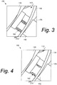
- Fig. 3 shows portions of a combustor 100 as may be described herein.
- an air path 110 may be configured between a liner 120 and a flow sleeve 130 for the flow of air 20 therethrough.
- the air path 110 also may be configured between other structures.
- the combustor 100 may include a number of fuel pegs or fuel injectors 140 positioned in the air path 110.
- the fuel injectors 140 likewise may have an aerodynamic airfoil or streamlined shape to optimize flame holding resistance. Other shapes may be used herein. Any number of the fuel injectors 140 may be used in any size or position.
- the fuel injectors 140 each may have a number of injector holes therein on one or both sides in any size or position. Other configurations and other components may be used herein.
- the combustor 100 also may include one or more crossfire tubes 170.
- the crossfire tube 170 may extend through the liner 120 and the flow sleeve 130 and may be positioned within the air path 110.
- a secondary function of the crossfire tube 170 is to provide purge air. Purge air may be fed to the crossfire tubes 170 at approximately the compressor discharge pressure so as to prevent unwanted migration of unburned fuel between adjacent combustors 100.
- each of the crossfire tubes 170 has a number of purge holes 180.
- the purge holes 180 may have any desired size or shape and any number may be used. Although a number of purge holes 180 are shown, a single purge hole 180 may be used herein.
- the purge holes 180 may be continuous, interrupted, or combinations thereof.
- the purge holes 180 may be positioned about a downstream side 190 of the crossfire tube 170.
- Fig. 3 shows an example of the purge holes 180 in a number of columns 200 extending in a circumferential direction.
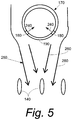
- Fig. 4 shows an example of the purge holes 180 positioned in a grouping 200 extending in an axial direction. Any number of columns 200 or groupings 220 may be used herein in any configuration or orientation with any number of purge holes 180 in each and/or combinations thereof.
- a flow of the purge gas 240 enters the purge holes 180 at about the compressor discharge pressure.
- the positioning of the purge holes 180 on the downstream side 190 of the crossfire tube 170 thus creates an area of boundary layer suction 250 given a pressure drop about the flow sleeve 130 (in terms of a percentage of compressor discharge pressure.
- This area of boundary layer suction 250 causes a wake 260 created by the flow of air 20 passing the crossfire tube 170 to be reduced in size in both width and length. As such, the wake 260 may be eliminated or reduced before reaching the fuel injectors 140.
- the reduction or elimination of the wake 260 thus may reduce downstream flow disturbances and the potential for recirculation zones.
- the elimination of such recirculation zones also should reduce the possibility of flame holding.
- the placement and sizing of the purge holes 180 may be optimized so as to maximize the area of the boundary layer suction 250 so as to reduce or eliminate the wake 260. Reducing the wake 260 also should enable early fuel introduction so as to reduce casing corrosion and the like.
- the downstream positioning of the purge holes 180 should reduce the pressure drop thereacross.
- the placement and definition of the purge holes 180 also may increase the heat transfer across the crossfire tubes 170 so as to provide an increased lifetime.
Landscapes
- Engineering & Computer Science (AREA)
- Chemical & Material Sciences (AREA)
- Combustion & Propulsion (AREA)
- Mechanical Engineering (AREA)
- General Engineering & Computer Science (AREA)
- Gas Burners (AREA)
- Pre-Mixing And Non-Premixing Gas Burner (AREA)
Claims (12)
- Brennkammer (100) zum Mischen eines Luftstroms (20) und eines Brennstoffstroms (30), umfassend:einen Luftpfad (110) für den Luftstrom (20);eine Vielzahl von Brennstoffeinspritzern (140), die in dem Luftpfad (110) für den Brennstoffstrom (30) positioniert sind; undein Querzündrohr (170), das innerhalb des Luftpfads (110) stromaufwärts der Vielzahl von Brennstoffeinspritzern (140) positioniert ist;wobei das Querzündrohr (170) eine Vielzahl von Spüllöchern (180) umfasst, die in einer Vielzahl von Spalten (200) positioniert sind, die auf einer stromabwärtigen Seite (190) davon positioniert sind, um einen Nachlauf (260) in dem Luftstrom (20) zu verringern, der durch das Querzündrohr (170) in dem Luftpfad (110) verursacht wird.
- Brennkammer (100) nach Anspruch 1, wobei der Luftpfad (110) durch eine Auskleidung (120) und eine Strömungshülse (130) definiert ist.
- Brennkammer (100) nach Anspruch 1 oder 2, wobei die Vielzahl von Spüllöchern (180) eine Umfangsrichtung (210) umfasst.
- Brennkammer (100) nach dem vorhergehenden Anspruch, die dazu ausgestaltet ist, dass die Spülluft den Querzündrohren (170) zugeführt wird, um ein Wandern von unverbranntem Brennstoff zwischen benachbarten Brennkammern (100) zu verhindern.
- Brennkammer (100) nach Anspruch 4, die dazu ausgestaltet ist, dass der Strom von Spülgas (240) einen Grenzschichtansaugbereich (250) stromabwärts des Querzündrohrs (170) erzeugt.
- Brennkammer (100) nach einem der vorhergehenden Ansprüche, die dazu ausgestaltet ist, dass der Nachlauf (260) stromaufwärts der Brennstoffeinspritzer (140) beseitigt oder verringert wird.
- Brennkammer (100) nach einem der vorhergehenden Ansprüche, ferner umfassend ein Paar Brennkammern (100) und wobei sich das Querzündrohr (170) zwischen dem Paar Brennkammern (100) erstreckt.
- Brennkammer (100) nach einem der vorhergehenden Ansprüche, ferner umfassend eine Vielzahl von Brennstoffdüsen (55) stromabwärts der Vielzahl von Brennstoffeinspritzern (140).
- Brennkammer (100) nach Anspruch 8, ferner umfassend eine Verbrennungszone (50) stromabwärts der Vielzahl von Brennstoffdüsen (55).
- Verfahren zum Betreiben eines Vordüse-Brennstoffeinspritzsystems (90), umfassend:Strömen von Luft (20) durch einen Luftpfad (110);Strömen von Brennstoff (30) durch eine Vielzahl von Brennstoffeinspritzern (140);Erzeugen eines Nachlaufs (260) in dem Luftstrom (20) stromaufwärts der Brennstoffeinspritzer (140) mit einem Querzündrohr (170);Strömen von Spülgas (240) durch eine Vielzahl von Spüllöchern (180) in dem Querzündrohr (170);Erzeugen eines Grenzschichtansaugbereichs (250) um das Querzündrohr (170) herum; undBeseitigen oder Verringern des Nachlaufs (260) stromaufwärts der Vielzahl von Brennstoffeinspritzern (140) durch den Grenzschichtansaugbereich (250).
- Verfahren nach Anspruch 10, ferner umfassend den Schritt des Verringerns einer Rezirkulationszone um die Vielzahl von Brennstoffeinspritzern (140).
- Verfahren nach Anspruch 10 oder 11, ferner umfassend den Schritt des Verringerns des Flammenhaltens um die Vielzahl von Brennstoffeinspritzern (140).
Applications Claiming Priority (1)
| Application Number | Priority Date | Filing Date | Title |
|---|---|---|---|
| US13/072,820 US8893501B2 (en) | 2011-03-28 | 2011-03-28 | Combustor crossfire tube |
Publications (3)
| Publication Number | Publication Date |
|---|---|
| EP2505921A2 EP2505921A2 (de) | 2012-10-03 |
| EP2505921A3 EP2505921A3 (de) | 2018-03-28 |
| EP2505921B1 true EP2505921B1 (de) | 2021-05-19 |
Family
ID=45954364
Family Applications (1)
| Application Number | Title | Priority Date | Filing Date |
|---|---|---|---|
| EP12161136.2A Active EP2505921B1 (de) | 2011-03-28 | 2012-03-23 | Kreuzfeuerbrennkammerohr mit Ausblaslöchern |
Country Status (3)
| Country | Link |
|---|---|
| US (1) | US8893501B2 (de) |
| EP (1) | EP2505921B1 (de) |
| CN (1) | CN102721084B (de) |
Families Citing this family (7)
| Publication number | Priority date | Publication date | Assignee | Title |
|---|---|---|---|---|
| US8899975B2 (en) | 2011-11-04 | 2014-12-02 | General Electric Company | Combustor having wake air injection |
| US9267687B2 (en) | 2011-11-04 | 2016-02-23 | General Electric Company | Combustion system having a venturi for reducing wakes in an airflow |
| US9328925B2 (en) * | 2012-11-15 | 2016-05-03 | General Electric Company | Cross-fire tube purging arrangement and method of purging a cross-fire tube |
| US9322553B2 (en) | 2013-05-08 | 2016-04-26 | General Electric Company | Wake manipulating structure for a turbine system |
| US9739201B2 (en) | 2013-05-08 | 2017-08-22 | General Electric Company | Wake reducing structure for a turbine system and method of reducing wake |
| US9435221B2 (en) | 2013-08-09 | 2016-09-06 | General Electric Company | Turbomachine airfoil positioning |
| FR3011620B1 (fr) * | 2013-10-04 | 2018-03-09 | Snecma | Chambre de combustion de turbomachine pourvue d'un passage d'entree d'air ameliore en aval d'un orifice de passage de bougie |
Family Cites Families (19)
| Publication number | Priority date | Publication date | Assignee | Title |
|---|---|---|---|---|
| US2621477A (en) * | 1948-06-03 | 1952-12-16 | Power Jets Res & Dev Ltd | Combustion apparatus having valve controlled passages for preheating the fuel-air mixture |
| US2983342A (en) | 1957-09-10 | 1961-05-09 | Walter C Howard | Telescopic mast |
| US3811274A (en) * | 1972-08-30 | 1974-05-21 | United Aircraft Corp | Crossover tube construction |
| US3991560A (en) * | 1975-01-29 | 1976-11-16 | Westinghouse Electric Corporation | Flexible interconnection for combustors |
| US5001896A (en) * | 1986-02-26 | 1991-03-26 | Hilt Milton B | Impingement cooled crossfire tube assembly in multiple-combustor gas turbine engine |
| US5361577A (en) * | 1991-07-15 | 1994-11-08 | General Electric Company | Spring loaded cross-fire tube |
| DE19547506B4 (de) * | 1995-12-19 | 2008-06-05 | Airbus Deutschland Gmbh | Verfahren und Brenner zum Verbrennen von Wasserstoff |
| US5896742A (en) | 1997-03-20 | 1999-04-27 | General Electric Co. | Tapered cross-fire tube for gas turbine combustors |
| JPH11211087A (ja) * | 1998-01-29 | 1999-08-06 | Toshiba Corp | ガスタービン火炎伝播管 |
| GB2339468B (en) * | 1998-07-11 | 2002-04-24 | Alstom Gas Turbines Ltd | Gas-turbine engine combustion system |
| US6334294B1 (en) | 2000-05-16 | 2002-01-01 | General Electric Company | Combustion crossfire tube with integral soft chamber |
| US6813889B2 (en) * | 2001-08-29 | 2004-11-09 | Hitachi, Ltd. | Gas turbine combustor and operating method thereof |
| US6606865B2 (en) | 2001-10-31 | 2003-08-19 | General Electric Company | Bellows type outer crossfire tube |
| US6705088B2 (en) | 2002-04-05 | 2004-03-16 | Power Systems Mfg, Llc | Advanced crossfire tube cooling scheme for gas turbine combustors |
| US6912838B2 (en) * | 2003-03-06 | 2005-07-05 | Power Systems Mfg, Llc | Coated crossfire tube assembly |
| US7712302B2 (en) | 2006-01-05 | 2010-05-11 | General Electric Company | Crossfire tube assembly for gas turbines |
| US7966820B2 (en) * | 2007-08-15 | 2011-06-28 | General Electric Company | Method and apparatus for combusting fuel within a gas turbine engine |
| JP4959523B2 (ja) * | 2007-11-29 | 2012-06-27 | 株式会社日立製作所 | 燃焼装置,燃焼装置の改造方法及び燃焼装置の燃料噴射方法 |
| US20100300107A1 (en) | 2009-05-29 | 2010-12-02 | General Electric Company | Method and flow sleeve profile reduction to extend combustor liner life |
-
2011
- 2011-03-28 US US13/072,820 patent/US8893501B2/en not_active Expired - Fee Related
-
2012
- 2012-03-23 EP EP12161136.2A patent/EP2505921B1/de active Active
- 2012-03-28 CN CN201210100310.1A patent/CN102721084B/zh not_active Expired - Fee Related
Non-Patent Citations (1)
| Title |
|---|
| None * |
Also Published As
| Publication number | Publication date |
|---|---|
| EP2505921A2 (de) | 2012-10-03 |
| US8893501B2 (en) | 2014-11-25 |
| EP2505921A3 (de) | 2018-03-28 |
| CN102721084B (zh) | 2016-02-03 |
| US20120247118A1 (en) | 2012-10-04 |
| CN102721084A (zh) | 2012-10-10 |
Similar Documents
| Publication | Publication Date | Title |
|---|---|---|
| US9416974B2 (en) | Combustor with fuel staggering for flame holding mitigation | |
| US8991187B2 (en) | Combustor with a lean pre-nozzle fuel injection system | |
| EP2505921B1 (de) | Kreuzfeuerbrennkammerohr mit Ausblaslöchern | |
| EP2626635B1 (de) | Brennkammeranordnung mit eingeschlossenem Wirbelhohlraum | |
| EP1400753B1 (de) | Gasturbinenvormischbrenner mit einer Einrichtung zur Verminderung von Flammenrückschlag | |
| CN102798147B (zh) | 用于燃气涡轮发动机中的流控制的系统和方法 | |
| US8371101B2 (en) | Radial inlet guide vanes for a combustor | |
| US20110000215A1 (en) | Combustor Can Flow Conditioner | |
| US8733108B2 (en) | Combustor and combustor screech mitigation methods | |
| US20120266602A1 (en) | Aerodynamic Fuel Nozzle | |
| EP2664854B1 (de) | Sekundäres Verbrennungssystem | |
| US9068750B2 (en) | Combustor with a pre-nozzle mixing cap assembly | |
| US9696037B2 (en) | Liner retaining feature for a combustor | |
| EP2682586B1 (de) | Gasturbinenbrennkammer und Betriebsverfahren für eine Gasturbinenbrennkammer | |
| EP2503243A1 (de) | Brennkammer mit Brennstoffdüsenauskleidung mit Fischgrätmuster-Rippen | |
| EP2618052A1 (de) | Brennstoffdüse | |
| EP2647910A2 (de) | Kraftstoffdiffusionsdüse einer Brennkammer | |
| US20140260302A1 (en) | DIFFUSION COMBUSTOR FUEL NOZZLE FOR LIMITING NOx EMISSIONS | |
| Zuo et al. | Radial inlet guide vanes for a combustor |
Legal Events
| Date | Code | Title | Description |
|---|---|---|---|
| PUAI | Public reference made under article 153(3) epc to a published international application that has entered the european phase |
Free format text: ORIGINAL CODE: 0009012 |
|
| AK | Designated contracting states |
Kind code of ref document: A2 Designated state(s): AL AT BE BG CH CY CZ DE DK EE ES FI FR GB GR HR HU IE IS IT LI LT LU LV MC MK MT NL NO PL PT RO RS SE SI SK SM TR |
|
| AX | Request for extension of the european patent |
Extension state: BA ME |
|
| PUAL | Search report despatched |
Free format text: ORIGINAL CODE: 0009013 |
|
| AK | Designated contracting states |
Kind code of ref document: A3 Designated state(s): AL AT BE BG CH CY CZ DE DK EE ES FI FR GB GR HR HU IE IS IT LI LT LU LV MC MK MT NL NO PL PT RO RS SE SI SK SM TR |
|
| AX | Request for extension of the european patent |
Extension state: BA ME |
|
| RIC1 | Information provided on ipc code assigned before grant |
Ipc: F23R 3/28 20060101ALI20180219BHEP Ipc: F23R 3/48 20060101AFI20180219BHEP |
|
| STAA | Information on the status of an ep patent application or granted ep patent |
Free format text: STATUS: REQUEST FOR EXAMINATION WAS MADE |
|
| 17P | Request for examination filed |
Effective date: 20180928 |
|
| RBV | Designated contracting states (corrected) |
Designated state(s): AL AT BE BG CH CY CZ DE DK EE ES FI FR GB GR HR HU IE IS IT LI LT LU LV MC MK MT NL NO PL PT RO RS SE SI SK SM TR |
|
| STAA | Information on the status of an ep patent application or granted ep patent |
Free format text: STATUS: EXAMINATION IS IN PROGRESS |
|
| 17Q | First examination report despatched |
Effective date: 20190118 |
|
| GRAP | Despatch of communication of intention to grant a patent |
Free format text: ORIGINAL CODE: EPIDOSNIGR1 |
|
| STAA | Information on the status of an ep patent application or granted ep patent |
Free format text: STATUS: GRANT OF PATENT IS INTENDED |
|
| INTG | Intention to grant announced |
Effective date: 20201218 |
|
| GRAS | Grant fee paid |
Free format text: ORIGINAL CODE: EPIDOSNIGR3 |
|
| GRAA | (expected) grant |
Free format text: ORIGINAL CODE: 0009210 |
|
| STAA | Information on the status of an ep patent application or granted ep patent |
Free format text: STATUS: THE PATENT HAS BEEN GRANTED |
|
| AK | Designated contracting states |
Kind code of ref document: B1 Designated state(s): AL AT BE BG CH CY CZ DE DK EE ES FI FR GB GR HR HU IE IS IT LI LT LU LV MC MK MT NL NO PL PT RO RS SE SI SK SM TR |
|
| REG | Reference to a national code |
Ref country code: GB Ref legal event code: FG4D |
|
| REG | Reference to a national code |
Ref country code: CH Ref legal event code: EP |
|
| REG | Reference to a national code |
Ref country code: DE Ref legal event code: R096 Ref document number: 602012075590 Country of ref document: DE |
|
| REG | Reference to a national code |
Ref country code: AT Ref legal event code: REF Ref document number: 1394333 Country of ref document: AT Kind code of ref document: T Effective date: 20210615 |
|
| REG | Reference to a national code |
Ref country code: IE Ref legal event code: FG4D |
|
| REG | Reference to a national code |
Ref country code: LT Ref legal event code: MG9D |
|
| REG | Reference to a national code |
Ref country code: AT Ref legal event code: MK05 Ref document number: 1394333 Country of ref document: AT Kind code of ref document: T Effective date: 20210519 |
|
| REG | Reference to a national code |
Ref country code: NL Ref legal event code: MP Effective date: 20210519 |
|
| PG25 | Lapsed in a contracting state [announced via postgrant information from national office to epo] |
Ref country code: HR Free format text: LAPSE BECAUSE OF FAILURE TO SUBMIT A TRANSLATION OF THE DESCRIPTION OR TO PAY THE FEE WITHIN THE PRESCRIBED TIME-LIMIT Effective date: 20210519 Ref country code: BG Free format text: LAPSE BECAUSE OF FAILURE TO SUBMIT A TRANSLATION OF THE DESCRIPTION OR TO PAY THE FEE WITHIN THE PRESCRIBED TIME-LIMIT Effective date: 20210819 Ref country code: AT Free format text: LAPSE BECAUSE OF FAILURE TO SUBMIT A TRANSLATION OF THE DESCRIPTION OR TO PAY THE FEE WITHIN THE PRESCRIBED TIME-LIMIT Effective date: 20210519 Ref country code: FI Free format text: LAPSE BECAUSE OF FAILURE TO SUBMIT A TRANSLATION OF THE DESCRIPTION OR TO PAY THE FEE WITHIN THE PRESCRIBED TIME-LIMIT Effective date: 20210519 Ref country code: LT Free format text: LAPSE BECAUSE OF FAILURE TO SUBMIT A TRANSLATION OF THE DESCRIPTION OR TO PAY THE FEE WITHIN THE PRESCRIBED TIME-LIMIT Effective date: 20210519 |
|
| PG25 | Lapsed in a contracting state [announced via postgrant information from national office to epo] |
Ref country code: ES Free format text: LAPSE BECAUSE OF FAILURE TO SUBMIT A TRANSLATION OF THE DESCRIPTION OR TO PAY THE FEE WITHIN THE PRESCRIBED TIME-LIMIT Effective date: 20210519 Ref country code: PL Free format text: LAPSE BECAUSE OF FAILURE TO SUBMIT A TRANSLATION OF THE DESCRIPTION OR TO PAY THE FEE WITHIN THE PRESCRIBED TIME-LIMIT Effective date: 20210519 Ref country code: NO Free format text: LAPSE BECAUSE OF FAILURE TO SUBMIT A TRANSLATION OF THE DESCRIPTION OR TO PAY THE FEE WITHIN THE PRESCRIBED TIME-LIMIT Effective date: 20210819 Ref country code: PT Free format text: LAPSE BECAUSE OF FAILURE TO SUBMIT A TRANSLATION OF THE DESCRIPTION OR TO PAY THE FEE WITHIN THE PRESCRIBED TIME-LIMIT Effective date: 20210920 Ref country code: LV Free format text: LAPSE BECAUSE OF FAILURE TO SUBMIT A TRANSLATION OF THE DESCRIPTION OR TO PAY THE FEE WITHIN THE PRESCRIBED TIME-LIMIT Effective date: 20210519 Ref country code: GR Free format text: LAPSE BECAUSE OF FAILURE TO SUBMIT A TRANSLATION OF THE DESCRIPTION OR TO PAY THE FEE WITHIN THE PRESCRIBED TIME-LIMIT Effective date: 20210820 Ref country code: IS Free format text: LAPSE BECAUSE OF FAILURE TO SUBMIT A TRANSLATION OF THE DESCRIPTION OR TO PAY THE FEE WITHIN THE PRESCRIBED TIME-LIMIT Effective date: 20210919 Ref country code: RS Free format text: LAPSE BECAUSE OF FAILURE TO SUBMIT A TRANSLATION OF THE DESCRIPTION OR TO PAY THE FEE WITHIN THE PRESCRIBED TIME-LIMIT Effective date: 20210519 Ref country code: SE Free format text: LAPSE BECAUSE OF FAILURE TO SUBMIT A TRANSLATION OF THE DESCRIPTION OR TO PAY THE FEE WITHIN THE PRESCRIBED TIME-LIMIT Effective date: 20210519 |
|
| PG25 | Lapsed in a contracting state [announced via postgrant information from national office to epo] |
Ref country code: NL Free format text: LAPSE BECAUSE OF FAILURE TO SUBMIT A TRANSLATION OF THE DESCRIPTION OR TO PAY THE FEE WITHIN THE PRESCRIBED TIME-LIMIT Effective date: 20210519 |
|
| PG25 | Lapsed in a contracting state [announced via postgrant information from national office to epo] |
Ref country code: SM Free format text: LAPSE BECAUSE OF FAILURE TO SUBMIT A TRANSLATION OF THE DESCRIPTION OR TO PAY THE FEE WITHIN THE PRESCRIBED TIME-LIMIT Effective date: 20210519 Ref country code: SK Free format text: LAPSE BECAUSE OF FAILURE TO SUBMIT A TRANSLATION OF THE DESCRIPTION OR TO PAY THE FEE WITHIN THE PRESCRIBED TIME-LIMIT Effective date: 20210519 Ref country code: DK Free format text: LAPSE BECAUSE OF FAILURE TO SUBMIT A TRANSLATION OF THE DESCRIPTION OR TO PAY THE FEE WITHIN THE PRESCRIBED TIME-LIMIT Effective date: 20210519 Ref country code: CZ Free format text: LAPSE BECAUSE OF FAILURE TO SUBMIT A TRANSLATION OF THE DESCRIPTION OR TO PAY THE FEE WITHIN THE PRESCRIBED TIME-LIMIT Effective date: 20210519 Ref country code: EE Free format text: LAPSE BECAUSE OF FAILURE TO SUBMIT A TRANSLATION OF THE DESCRIPTION OR TO PAY THE FEE WITHIN THE PRESCRIBED TIME-LIMIT Effective date: 20210519 Ref country code: RO Free format text: LAPSE BECAUSE OF FAILURE TO SUBMIT A TRANSLATION OF THE DESCRIPTION OR TO PAY THE FEE WITHIN THE PRESCRIBED TIME-LIMIT Effective date: 20210519 |
|
| REG | Reference to a national code |
Ref country code: DE Ref legal event code: R097 Ref document number: 602012075590 Country of ref document: DE |
|
| PLBE | No opposition filed within time limit |
Free format text: ORIGINAL CODE: 0009261 |
|
| STAA | Information on the status of an ep patent application or granted ep patent |
Free format text: STATUS: NO OPPOSITION FILED WITHIN TIME LIMIT |
|
| 26N | No opposition filed |
Effective date: 20220222 |
|
| PGFP | Annual fee paid to national office [announced via postgrant information from national office to epo] |
Ref country code: DE Payment date: 20220217 Year of fee payment: 11 |
|
| PG25 | Lapsed in a contracting state [announced via postgrant information from national office to epo] |
Ref country code: IS Free format text: LAPSE BECAUSE OF FAILURE TO SUBMIT A TRANSLATION OF THE DESCRIPTION OR TO PAY THE FEE WITHIN THE PRESCRIBED TIME-LIMIT Effective date: 20210919 Ref country code: AL Free format text: LAPSE BECAUSE OF FAILURE TO SUBMIT A TRANSLATION OF THE DESCRIPTION OR TO PAY THE FEE WITHIN THE PRESCRIBED TIME-LIMIT Effective date: 20210519 |
|
| PG25 | Lapsed in a contracting state [announced via postgrant information from national office to epo] |
Ref country code: IT Free format text: LAPSE BECAUSE OF FAILURE TO SUBMIT A TRANSLATION OF THE DESCRIPTION OR TO PAY THE FEE WITHIN THE PRESCRIBED TIME-LIMIT Effective date: 20210519 |
|
| PG25 | Lapsed in a contracting state [announced via postgrant information from national office to epo] |
Ref country code: MC Free format text: LAPSE BECAUSE OF FAILURE TO SUBMIT A TRANSLATION OF THE DESCRIPTION OR TO PAY THE FEE WITHIN THE PRESCRIBED TIME-LIMIT Effective date: 20210519 |
|
| REG | Reference to a national code |
Ref country code: CH Ref legal event code: PL |
|
| GBPC | Gb: european patent ceased through non-payment of renewal fee |
Effective date: 20220323 |
|
| REG | Reference to a national code |
Ref country code: BE Ref legal event code: MM Effective date: 20220331 |
|
| PG25 | Lapsed in a contracting state [announced via postgrant information from national office to epo] |
Ref country code: LU Free format text: LAPSE BECAUSE OF NON-PAYMENT OF DUE FEES Effective date: 20220323 Ref country code: LI Free format text: LAPSE BECAUSE OF NON-PAYMENT OF DUE FEES Effective date: 20220331 Ref country code: IE Free format text: LAPSE BECAUSE OF NON-PAYMENT OF DUE FEES Effective date: 20220323 Ref country code: GB Free format text: LAPSE BECAUSE OF NON-PAYMENT OF DUE FEES Effective date: 20220323 Ref country code: FR Free format text: LAPSE BECAUSE OF NON-PAYMENT OF DUE FEES Effective date: 20220331 Ref country code: CH Free format text: LAPSE BECAUSE OF NON-PAYMENT OF DUE FEES Effective date: 20220331 |
|
| PG25 | Lapsed in a contracting state [announced via postgrant information from national office to epo] |
Ref country code: BE Free format text: LAPSE BECAUSE OF NON-PAYMENT OF DUE FEES Effective date: 20220331 |
|
| REG | Reference to a national code |
Ref country code: DE Ref legal event code: R119 Ref document number: 602012075590 Country of ref document: DE |
|
| PG25 | Lapsed in a contracting state [announced via postgrant information from national office to epo] |
Ref country code: DE Free format text: LAPSE BECAUSE OF NON-PAYMENT OF DUE FEES Effective date: 20231003 |
|
| PG25 | Lapsed in a contracting state [announced via postgrant information from national office to epo] |
Ref country code: HU Free format text: LAPSE BECAUSE OF FAILURE TO SUBMIT A TRANSLATION OF THE DESCRIPTION OR TO PAY THE FEE WITHIN THE PRESCRIBED TIME-LIMIT; INVALID AB INITIO Effective date: 20120323 |
|
| PG25 | Lapsed in a contracting state [announced via postgrant information from national office to epo] |
Ref country code: MK Free format text: LAPSE BECAUSE OF FAILURE TO SUBMIT A TRANSLATION OF THE DESCRIPTION OR TO PAY THE FEE WITHIN THE PRESCRIBED TIME-LIMIT Effective date: 20210519 Ref country code: CY Free format text: LAPSE BECAUSE OF FAILURE TO SUBMIT A TRANSLATION OF THE DESCRIPTION OR TO PAY THE FEE WITHIN THE PRESCRIBED TIME-LIMIT Effective date: 20210519 |
|
| PG25 | Lapsed in a contracting state [announced via postgrant information from national office to epo] |
Ref country code: TR Free format text: LAPSE BECAUSE OF FAILURE TO SUBMIT A TRANSLATION OF THE DESCRIPTION OR TO PAY THE FEE WITHIN THE PRESCRIBED TIME-LIMIT Effective date: 20210519 |