EP2505808A2 - Vorrichtung zum Mischen von Treibstoff und Luft eines Strahltriebwerks - Google Patents
Vorrichtung zum Mischen von Treibstoff und Luft eines Strahltriebwerks Download PDFInfo
- Publication number
- EP2505808A2 EP2505808A2 EP12161477A EP12161477A EP2505808A2 EP 2505808 A2 EP2505808 A2 EP 2505808A2 EP 12161477 A EP12161477 A EP 12161477A EP 12161477 A EP12161477 A EP 12161477A EP 2505808 A2 EP2505808 A2 EP 2505808A2
- Authority
- EP
- European Patent Office
- Prior art keywords
- air
- fuel
- channel
- guide elements
- mixing
- Prior art date
- Legal status (The legal status is an assumption and is not a legal conclusion. Google has not performed a legal analysis and makes no representation as to the accuracy of the status listed.)
- Granted
Links
Images


Classifications
-
- F—MECHANICAL ENGINEERING; LIGHTING; HEATING; WEAPONS; BLASTING
- F23—COMBUSTION APPARATUS; COMBUSTION PROCESSES
- F23R—GENERATING COMBUSTION PRODUCTS OF HIGH PRESSURE OR HIGH VELOCITY, e.g. GAS-TURBINE COMBUSTION CHAMBERS
- F23R3/00—Continuous combustion chambers using liquid or gaseous fuel
- F23R3/02—Continuous combustion chambers using liquid or gaseous fuel characterised by the air-flow or gas-flow configuration
- F23R3/16—Continuous combustion chambers using liquid or gaseous fuel characterised by the air-flow or gas-flow configuration with devices inside the flame tube or the combustion chamber to influence the air or gas flow
-
- F—MECHANICAL ENGINEERING; LIGHTING; HEATING; WEAPONS; BLASTING
- F02—COMBUSTION ENGINES; HOT-GAS OR COMBUSTION-PRODUCT ENGINE PLANTS
- F02K—JET-PROPULSION PLANTS
- F02K1/00—Plants characterised by the form or arrangement of the jet pipe or nozzle; Jet pipes or nozzles peculiar thereto
- F02K1/38—Introducing air inside the jet
- F02K1/386—Introducing air inside the jet mixing devices in the jet pipe, e.g. for mixing primary and secondary flow
-
- F—MECHANICAL ENGINEERING; LIGHTING; HEATING; WEAPONS; BLASTING
- F02—COMBUSTION ENGINES; HOT-GAS OR COMBUSTION-PRODUCT ENGINE PLANTS
- F02K—JET-PROPULSION PLANTS
- F02K3/00—Plants including a gas turbine driving a compressor or a ducted fan
- F02K3/08—Plants including a gas turbine driving a compressor or a ducted fan with supplementary heating of the working fluid; Control thereof
- F02K3/10—Plants including a gas turbine driving a compressor or a ducted fan with supplementary heating of the working fluid; Control thereof by after-burners
-
- F—MECHANICAL ENGINEERING; LIGHTING; HEATING; WEAPONS; BLASTING
- F23—COMBUSTION APPARATUS; COMBUSTION PROCESSES
- F23D—BURNERS
- F23D14/00—Burners for combustion of a gas, e.g. of a gas stored under pressure as a liquid
- F23D14/46—Details
- F23D14/62—Mixing devices; Mixing tubes
-
- F—MECHANICAL ENGINEERING; LIGHTING; HEATING; WEAPONS; BLASTING
- F23—COMBUSTION APPARATUS; COMBUSTION PROCESSES
- F23R—GENERATING COMBUSTION PRODUCTS OF HIGH PRESSURE OR HIGH VELOCITY, e.g. GAS-TURBINE COMBUSTION CHAMBERS
- F23R3/00—Continuous combustion chambers using liquid or gaseous fuel
- F23R3/02—Continuous combustion chambers using liquid or gaseous fuel characterised by the air-flow or gas-flow configuration
- F23R3/04—Air inlet arrangements
- F23R3/10—Air inlet arrangements for primary air
- F23R3/12—Air inlet arrangements for primary air inducing a vortex
- F23R3/14—Air inlet arrangements for primary air inducing a vortex by using swirl vanes
-
- F—MECHANICAL ENGINEERING; LIGHTING; HEATING; WEAPONS; BLASTING
- F23—COMBUSTION APPARATUS; COMBUSTION PROCESSES
- F23R—GENERATING COMBUSTION PRODUCTS OF HIGH PRESSURE OR HIGH VELOCITY, e.g. GAS-TURBINE COMBUSTION CHAMBERS
- F23R3/00—Continuous combustion chambers using liquid or gaseous fuel
- F23R3/28—Continuous combustion chambers using liquid or gaseous fuel characterised by the fuel supply
- F23R3/286—Continuous combustion chambers using liquid or gaseous fuel characterised by the fuel supply having fuel-air premixing devices
-
- F—MECHANICAL ENGINEERING; LIGHTING; HEATING; WEAPONS; BLASTING
- F23—COMBUSTION APPARATUS; COMBUSTION PROCESSES
- F23D—BURNERS
- F23D2900/00—Special features of, or arrangements for burners using fluid fuels or solid fuels suspended in a carrier gas
- F23D2900/00003—Fuel or fuel-air mixtures flow distribution devices upstream of the outlet
-
- F—MECHANICAL ENGINEERING; LIGHTING; HEATING; WEAPONS; BLASTING
- F23—COMBUSTION APPARATUS; COMBUSTION PROCESSES
- F23D—BURNERS
- F23D2900/00—Special features of, or arrangements for burners using fluid fuels or solid fuels suspended in a carrier gas
- F23D2900/14—Special features of gas burners
- F23D2900/14021—Premixing burners with swirling or vortices creating means for fuel or air
-
- F—MECHANICAL ENGINEERING; LIGHTING; HEATING; WEAPONS; BLASTING
- F23—COMBUSTION APPARATUS; COMBUSTION PROCESSES
- F23R—GENERATING COMBUSTION PRODUCTS OF HIGH PRESSURE OR HIGH VELOCITY, e.g. GAS-TURBINE COMBUSTION CHAMBERS
- F23R2900/00—Special features of, or arrangements for continuous combustion chambers; Combustion processes therefor
- F23R2900/00014—Reducing thermo-acoustic vibrations by passive means, e.g. by Helmholtz resonators
Definitions
- the invention relates to a device for mixing fuel and air of a jet engine according to the closer defined in the preamble of claim 1.
- jet engines or gas turbines work on the principle of recoil drive.
- jet engines suck in the ambient air and expel combustion products and partly air as a hot drive jet again, wherein a thrust force is generated by the recoil.
- the sucked ambient air is compressed in each case in the area of a compressor.
- the fuel which is typically kerosene, is injected into the air stream and then burned in the combustion chamber.
- the air-fuel mixture is ignited by spark plugs in the combustion chamber. Subsequently, the combustion of the present in the combustion chamber air-fuel mixture is carried out continuously without spark ignition.
- annular combustion chamber arrangements represent a gas-dynamic optimum for jet engines. They are very easy to implement and have a low installation space requirement in the axial direction of a jet engine since no deflections of the mixture to be combusted are to be provided in the combustion chamber between a compressor and a turbine of a jet engine.
- the combustion chamber is a plurality of fuel injection valves or devices for mixing fuel and air, also called burner, upstream, over the fuel is mixed with an air stream and introduced into an annular combustion chamber.
- the guide elements In the field of devices for mixing air and fuel, air and fuel are passed through several channels, wherein the guided in the jet engine air flow is twisted by means of vanes in the region of the device to ensure a mixture between the air and the fuel.
- the guide elements generally represent profiled grids, which are also known from compressor or turbine technology. Their number at the periphery of the burner is arbitrary and it can be used several rows of such guide elements, depending on how many air channels for the mixture are available.
- the trailing edges of the guide elements facing away in the flow direction of the air flow are straight and thin, in order to ensure a low-loss outflow of the profile flow or a free flow around the guide elements around.
- a disadvantage is that during operation of the jet engines in so-called follow-up areas or follow-up areas of the vanes, which are present in relation to the flow direction of the air flow downstream of the trailing edges of the vanes, fuel collects and no uniform mixture of air and fuel is achieved. Outside the wake areas, fuel and air are well mixed.
- the undesirable fuel accumulation in the region of the wake zones which are also referred to as dead water areas, results from the fact that a flow velocity in the region of the wake zones is almost zero.
- the mixing between the air flow and the fuel is particularly hindered by the fact that between the free flow and the wake areas, a shear layer is formed, which prevents mixing of both areas.
- the present invention is therefore based on the object to provide an apparatus for mixing fuel and air of a jet engine, by means of which a good mixing between air and fuel is achieved and the accumulation of fuel in wake zones of guide elements in a structurally simple way and Way is avoided.
- the guide elements are formed in a rear end region with respect to a flow direction of the air with at least one at least approximately at least partially executed with a sharp edge forward and / or return relative to the flow direction.
- the guide elements at least partially each have a preferably serrated trailing edge to produce so-called trailing edge vortex downstream of the guide elements and to achieve improved mixing of air and fuel.
- the trailing edge vortex prevent the known from practice accumulation of fuel in wake areas of the Guiding elements, whereby an improved mixing of air and fuel and thus also improved combustion of the air-fuel mixture in the region of a device downstream of the combustion chamber can be achieved.
- a particularly good mixing between air and fuel is achieved when the at least one forward and / or return of the vanes is at least partially triangular, since in such an embodiment of the vanes the Schukantenwirbel in a high degree of mixing ensuring extent during operation of a Jet engine present.
- a good mixing of air and fuel is also achieved if the at least one forward and / or return of the guide elements is at least partially trapezoidal.
- the guide elements with multiple projections and recesses whose shape and distances from each other at least partially vary.
- the guide elements with multiple projections and recesses whose shape and distances are equal to each other.
- the air-carrying channel is designed as an annular channel and surrounds the fuel-carrying channel.
- the device according to the invention also has a low space requirement.
- Fig. 1 shows a longitudinal sectional view of a jet engine 1, which is designed with a bypass duct 2. Furthermore, the jet engine 1 is formed with an inlet region 3, which is followed downstream by a fan 4 in a manner known per se. Again downstream of the fan 4, the fluid flow in the jet engine 1 is divided into a secondary flow and a core flow, wherein the secondary flow through the bypass channel 2 and the core flow flows into an engine core 5, which in turn in a conventional manner with a compressor device 6, a burner 7 and a turbine device 8 is executed.
- the burner 7 On the flow input side, the burner 7 is formed with a device 9 for mixing fuel and air, which in an in Fig. 1 designated area II is provided.
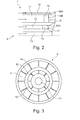
- FIG. 2 is an enlarged partial view of the in Fig. 1 closer marked area II, which includes the device 9, shown in more detail. From the illustration according to Fig. 2 It is apparent that the device 9 for mixing fuel and air of the jet engine 1 with a plurality of air-carrying channels 11 and 12 and two fuel-carrying channels 10 and 13 are formed.
- the air guiding channels 11 and 12 are present in each case over the channel height of the channels 11 and 12 extending and in in Fig. 3 closer to the manner shown distributed over the circumference of the channels 11 and 12 arranged guide elements 14, 15, in the region of the air in the leading channels 11 and 12 flowing air to improve a mixing between the air and the fuel downstream of the channels 11 and 12 a twist can be imposed.
- the guide elements 14 and 15 arranged in the channels 11 and 12 are in a rear end region in the flow direction of the air or in the region of a trailing edge 16, 17, in each case with respect to the flow direction in the in FIG Fig. 2 as in FIG. 4 to FIG. 12 at least one at least approximately at least partially executed with pointed edge projection 16A and 17A and / or formed with at least one recess 16B to at least approximately jagged the trailing edges 16 and 17 and the air flow when leaving the guide elements 14 and 15th imprinting so-called trailing edge vortices, by means of which improved mixing between the air guided in the engine core 5 and the fuel supplied in the area of the device 9 is ensured.
- the guide elements 14 and 15 Due to the design of the guide elements 14 and 15 with projections and / or recesses, the guide elements 14 and 15 compared to known from the prior art guide elements, which are formed with straight trailing edges, with a regular or irregular serrated trailing edge course designed to avoid fuel accumulation downstream of the guide elements.
- a good degree of mixing is achieved in particular if the prongs formed by the projections and / or recesses of the guide elements 14, 15 in the region of the trailing edges 16, 17 are at least partially triangular and / or trapezoidal in shape and have sharp edges. Wavy trailing edges, d. H. round shapes and edges are less suitable for forming the degree of mixing improving trailing eddies downstream of the vanes 14 and 15 as compared to pointed peaks.
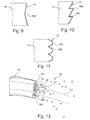
- FIG. 5 to FIG. 12 show in each case different embodiments of a guide element 14, which is formed in the region of its trailing edge 16 each with a different number of projections and / or recesses, each with differently executed teeth.
- a three-dimensional view of a guide element 14 with a serrated trailing edge 16 is shown, which represents a profiled grid with a blade profile.
- the trailing edge eddies 18 produced in the region of the serrated trailing edge 16 improve the mixing of fuel 19 and air, since the trailing region arranged downstream of the guide element 14 20 can interact with the free flow 21 in the jet engine 1. This results from the fact that the trailing edge eddies 18 break up the prior art shear layer 22 and result in a more homogeneous distribution of the air-fuel mixture and thus more efficient and effective combustion.
Landscapes
- Engineering & Computer Science (AREA)
- Chemical & Material Sciences (AREA)
- Combustion & Propulsion (AREA)
- Mechanical Engineering (AREA)
- General Engineering & Computer Science (AREA)
- Fuel-Injection Apparatus (AREA)
- Turbine Rotor Nozzle Sealing (AREA)
- Combustion Methods Of Internal-Combustion Engines (AREA)
Abstract
Description
- Die Erfindung betrifft eine Vorrichtung zum Mischen von Treibstoff und Luft eines Strahltriebwerkes gemäß der im Oberbegriff des Patentanspruches 1 näher definierten Art.
- Aus der Praxis bekannte Strahltriebwerke bzw. Gasturbinen arbeiten nach dem Prinzip des Rückstoßantriebes. Im Betrieb saugen Strahltriebwerke die Umgebungsluft an und stoßen Verbrennungsprodukte und zum Teil Luft als heißen Antriebsstrahl wieder aus, wobei durch den Rückstoß eine Schubkraft erzeugt wird. Die angesaugte Umgebungsluft wird im Bereich eines Verdichters jeweils komprimiert. In einer nachfolgenden Brennkammer wird der Treibstoff, der in der Regel Kerosin ist, in den Luftstrom eingespritzt und anschließend in der Brennkammer verbrannt. Beim Triebwerksstart wird das Luft-Treibstoff-Gemisch durch Zündkerzen in der Brennkammer gezündet. Anschließend erfolgt die Verbrennung des in der Brennkammer vorhandenen Luft-Treibstoff-Gemisches ohne Fremdzündung kontinuierlich.
- So genannte Ringbrennkammeranordnungen stellen ein gasdynamisches Optimum für Strahltriebwerke dar. Sie sind sehr leicht ausführbar und weisen in axialer Richtung eines Strahltriebwerkes einen geringen Bauraumbedarf auf, da zwischen einem Verdichter und einer Turbine eines Strahltriebwerkes jeweils keine Umlenkungen des zu verbrennenden Gemisches in der Brennkammer vorzusehen sind. Der Brennkammer sind mehrere Kraftstoffeinspritzventile bzw. Vorrichtungen zum Mischen von Treibstoff und Luft, auch Brenner genannt, vorgeschaltet, über die der Treibstoff mit einem Luftstrom vermischt und in einen ringförmigen Brennraum eingeleitet wird.
- Im Bereich der Vorrichtungen zum Mischen von Luft und Treibstoff wird Luft und Treibstoff durch mehrere Kanäle geführt, wobei der im Strahltriebwerk geführte Luftstrom mit Hilfe von Leitelementen im Bereich der Vorrichtung verdrallt wird, um eine Vermischung zwischen der Luft und dem Treibstoff zu gewährleisten. Die Leitelemente stellen im Allgemeinen profilierte Gitter dar, die auch aus der Verdichter- oder Turbinentechnik bekannt sind. Ihre Anzahl am Umfang des Brenners ist dabei beliebig und es können mehrere Reihen solcher Leitelemente Verwendung finden, je nach dem wie viele Luftkanäle für die Mischung vorhanden sind. Die in Strömungsrichtung des Luftstromes abgewandten Hinterkanten der Leitelemente sind gerade und dünn ausgeführt, um eine verlustarme Abströmung der Profilumströmung bzw. einer freien Strömung um die Leitelemente herum zu gewährleisten.
- Nachteilig dabei ist jedoch, dass sich im Betrieb der Strahltriebwerke in so genannten Nachlaufgebieten bzw. Nachlaufbereichen der Leitelemente, die in Bezug auf die Strömungsrichtung des Luftstroms stromab der Hinterkanten der Leitelemente vorliegen, Treibstoff sammelt und keine gleichmäßige Mischung von Luft und Treibstoff erreicht wird. Außerhalb der Nachlaufbereiche sind Treibstoff und Luft gut durchmischt. Die unerwünschte Treibstoffansammlung im Bereich der Nachlaufgebiete, die auch als Totwassergebiete bezeichnet werden, resultiert aus der Tatsache, dass eine Strömungsgeschwindigkeit im Bereich der Nachlaufgebiete nahezu gleich Null ist. Die Durchmischung zwischen dem Luftstrom und dem Treibstoff wird besonders dadurch behindert, dass zwischen der freien Strömung und den Nachlaufgebieten eine Scherschicht entsteht, die eine Durchmischung beider Gebiete verhindert.
- Der vorliegenden Erfindung liegt daher die Aufgabe zu Grunde, eine Vorrichtung zum Mischen von Treibstoff und Luft eines Strahltriebwerkes zur Verfügung zu stellen, mittels der eine gute Durchmischung zwischen Luft und Treibstoff erreicht wird und die Ansammlung von Treibstoff in Nachlaufbereichen von Leitelementen auf konstruktiv einfache Art und Weise vermieden wird.
- Erfindungsgemäß wird diese Aufgabe mit einer Vorrichtung mit den Merkmalen des Patentanspruches 1 gelöst.
- Bei der erfindungsgemäßen Vorrichtung zum Mischen von Treibstoff und Luft eines Strahltriebwerkes mit wenigstens einem Luft führenden Kanal und wenigstens einem weiteren Treibstoff führenden Kanal sind zumindest in dem Luft führenden Kanal sich über die Kanalhöhe erstreckende und über den Umfang des Kanals verteilt angeordnete Leitelemente vorgesehen, in deren Bereich der im Luft führenden Kanal strömenden Luft zur Verbesserung einer Vermischung zwischen der Luft und dem Treibstoff stromab der Kanäle ein Drall ausprägbar ist.
- Zur Vermeidung von Treibstoffansammlungen in stromab der Leitelemente vorliegenden Nachlaufgebieten sind die Leitelemente in einem in Bezug auf eine Strömungsrichtung der Luft hinteren Endbereich mit gegenüber der Strömungsrichtung mindestens einem wenigstens annähernd zumindest bereichsweise mit spitzer Kante ausgeführten Vor- und/oder Rücksprung ausgebildet. Damit weisen die Leitelemente zumindest bereichsweise jeweils eine vorzugsweise gezackte Hinterkante auf, um stromab der Leitelemente so genannte Hinterkantenwirbel zu erzeugen und eine verbesserte Durchmischung von Luft und Treibstoff zu erreichen. Die Hinterkantenwirbel verhindern die aus der Praxis bekannte Ansammlung von Treibstoff in Nachlaufgebieten der Leitelemente, womit eine verbesserte Vermischung von Luft und Treibstoff und somit auch eine verbesserte Verbrennung des Luft-Treibstoff-Gemisches im Bereich einer der Vorrichtung nachgeschalteten Brennkammer erzielt werden.
- Eine besonders gute Vermischung zwischen Luft und Treibstoff wird dann erreicht, wenn der mindestens eine Vor- und/oder Rücksprung der Leitelemente wenigstens bereichsweise dreieckförmig ausgeführt ist, da bei einer solchen Ausführung der Leitelemente die Hinterkantenwirbel in einem einen hohen Vermischungsgrad gewährleistenden Umfang während des Betriebes eines Strahltriebwerkes vorliegen.
- Eine gute Durchmischung von Luft und Treibstoff wird auch dann erreicht, wenn der mindestens eine Vor- und/oder Rücksprung der Leitelemente wenigstens bereichsweise trapezförmig ausgeführt ist.
- In Abhängigkeit des jeweils vorliegenden Anwendungsfalles besteht auch die Möglichkeit, zur Erzielung einer guten Durchmischung von Luft und Treibstoff die Leitelemente mit mehreren Vor- und Rücksprüngen auszubilden, deren Form und Abstände zueinander jeweils zumindest teilweise variieren.
- Wiederum in Abhängigkeit des jeweils vorliegenden Anwendungsfalles besteht auch die Möglichkeit, die Leitelemente mit mehreren Vor- und Rücksprüngen auszubilden, deren Form und Abstände zueinander gleich sind.
- Bei einer weiteren vorteilhaften und bauraumgünstigen Ausführungsform ist der Luft führende Kanal als Ringkanal ausgeführt und umgibt den Treibstoff führenden Kanal.
- Sind zwei konzentrisch angeordnete und jeweils als Ringkanal ausgeführte Luft führende Kanäle vorgesehen, die den Treibstoff führenden Kanal umgeben, weist die erfindungsgemäße Vorrichtung ebenfalls einen geringen Bauraumbedarf auf.
- Sowohl die in den Patentansprüchen angegebenen Merkmale als auch die in den nachfolgenden Ausführungsbeispielen der erfindungsgemäßen Vorrichtung angegebenen Merkmale sind jeweils für sich alleine oder in beliebiger Kombination miteinander geeignet, den erfindungsgemäßen Gegenstand weiterzubilden. Die jeweiligen Merkmalskombinationen stellen hinsichtlich der Weiterbildung des Gegenstandes nach der Erfindung keine Einschränkung dar, sondern weisen im Wesentlichen lediglich beispielhaften Charakter auf.
- Weitere Vorteile und vorteilhafte Ausführungsformen der erfindungsgemäßen Vorrichtung ergeben sich aus den Patentansprüchen und den nachfolgend unter Bezugnahme auf die Zeichnung prinzipmäßig beschriebenen Ausführungsbeispielen.
- Es zeigt:
- Fig. 1
- eine stark schematisierte Längsschnittansicht eines Strahltriebwerkes, die mit einer Vorrichtung zum Mischen von Treibstoff und Luft ausgeführt ist;
- Fig. 2
- eine vergrößerte Teildarstellung eines in
Fig. 1 näher gekennzeichnet Bereiches II der die Vorrichtung zum Mischen von Luft und Treibstoff umfasst; - Fig. 3
- eine Seitenansicht der Vorrichtung zum Mischen von Luft und Treibstoff in Alleinstellung;
- Fig. 4
- eine schematisierte Seiteneinzelansicht eines Leitelementes der Vorrichtung zum Mischen von Luft und Treibstoff;
- Fig. 5 bis Fig. 11
- mehrere
Fig. 4 entsprechende Darstellungen verschiedener Ausführungen von Leitelementen; und - Fig. 12
- eine vereinfachte dreidimensionale Einzelansicht eines Leitelementes.
-
Fig. 1 zeigt eine Längsschnittansicht eines Strahltriebwerkes 1, das mit einem Nebenstromkanal 2 ausgeführt ist. Des Weiteren ist das Strahltriebwerk 1 mit einem Einlaufbereich 3 ausgebildet, an den sich stromab ein Bläser 4 in an sich bekannter Art und Weise anschließt. Wiederum stromab des Bläsers 4 teilt sich der Fluidstrom im Strahltriebwerk 1 in einen Nebenstrom und einen Kernstrom auf, wobei der Nebenstrom durch den Nebenstromkanal 2 und der Kernstrom in einen Triebwerkskern 5 strömt, der wiederum in an sich bekannter Art und Weise mit einer Verdichtereinrichtung 6, einem Brenner 7 und einer Turbineneinrichtung 8 ausgeführt ist. - Strömungseingangsseitig ist der Brenner 7 mit einer Vorrichtung 9 zum Mischen von Treibstoff und Luft ausgebildet, die in einem in
Fig. 1 näher gekennzeichneten Bereich II vorgesehen ist. - In
Fig. 2 ist eine vergrößerte Teilansicht des inFig. 1 näher gekennzeichneten Bereiches II, der die Vorrichtung 9 umfasst, näher dargestellt. Aus der Darstellung gemäßFig. 2 geht hervor, dass die Vorrichtung 9 zum Mischen von Treibstoff und Luft des Strahltriebwerkes 1 mit mehreren Luft führenden Kanälen 11 und 12 und zwei Treibstoff führenden Kanälen 10 und 13 ausgebildet sind. In den Luft führenden Kanälen 11 und 12 sind vorliegend sich jeweils über die Kanalhöhe der Kanäle 11 und 12 erstreckende und in inFig. 3 näher dargestellter Art und Weise über den Umfang der Kanäle 11 und 12 verteilt angeordnete Leitelemente 14, 15 vorgesehen, in deren Bereich der in den Luft führenden Kanälen 11 und 12 strömenden Luft zur Verbesserung einer Vermischung zwischen der Luft und des Treibstoffes stromab der Kanäle 11 und 12 ein Drall aufprägbar ist. - Die in den Kanälen 11 und 12 angeordneten Leitelemente 14 und 15 sind in einem in Strömungsrichtung der Luft hinteren Endbereich bzw. im Bereich einer Hinterkante 16, 17 jeweils mit gegenüber der Strömungsrichtung in der in
Fig. 2 sowie inFig. 4 bis Fig. 12 näher dargestellten Art und Weise mindestens einem wenigstens annähernd zumindest bereichsweise mit spitzer Kante ausgeführten Vorsprung 16A bzw. 17A und/oder mit wenigstens einem Rücksprung 16B ausgebildet, um die Hinterkanten 16 und 17 wenigstens annähernd gezackt auszuführen und der Luftströmung beim Verlassen der Leitelemente 14 und 15 so genannten Hinterkantenwirbel aufzuprägen, mittels welchen eine verbesserte Durchmischung zwischen der im Triebwerkskern 5 geführten Luft und dem im Bereich der Vorrichtung 9 zugeführten Treibstoff gewährleistet ist. - Durch die Ausgestaltung der Leitelemente 14 und 15 mit Vor- und/oder Rücksprüngen sind die Leitelemente 14 und 15 im Vergleich zu aus dem Stand der Technik bekannten Leitelementen, die mit geraden Hinterkanten ausgebildet sind, mit einem regelmäßigen oder unregelmäßigen gezackten Hinterkantenverlauf ausgeführt, um stromab der Leitelemente Treibstoffansammlungen zu vermeiden.
- Die Anzahl der durch die Vor- und Rücksprünge im Bereich der Hinterkanten 16 und 17 gebildeten Zacken, ihre Positionierung zueinander, d. h. ein Abstand A zwischen zwei Zacken, eine Zackentiefe T sowie Winkel B und C der Zackenflanken werden in Abhängigkeit des jeweils vorliegenden Anwendungsfalles ausgewählt, um eine möglichst gute Durchmischung von Luft und Treibstoff besonders auch in den Nachlaufgebieten der Leitelemente 14, 15 zu erreichen.
- Ein guter Vermischungsgrad wird besonders dann erreicht, wenn die durch die Vor- und/oder Rücksprünge der Leitelemente 14, 15 im Bereich der Hinterkanten 16, 17 gebildeten Zacken wenigstens bereichsweise dreieckförmig und/oder trapezförmig ausgeführt sind und spitze Kanten aufweisen. Wellenförmige Hinterkanten, d. h. runde Formen und Kanten, sind zur Bildung von den Vermischungsgrad verbessernden Hinterkantenwirbeln stromab der Leitelemente 14 und 15 im Vergleich zu spitz zu laufenden Zacken weniger geeignet.
-
Fig. 5 bis Fig. 12 zeigen jeweils verschiedene Ausführungsformen eines Leitelementes 14, das im Bereich seiner Hinterkante 16 jeweils mit unterschiedlicher Anzahl an Vor- und/oder Rücksprüngen mit jeweils unterschiedlich ausgeführten Zacken ausgebildet ist. - In
Fig. 12 ist eine dreidimensionale Ansicht eines Leitelementes 14 mit gezackter Hinterkante 16 gezeigt, das ein profiliertes Gitter mit einem Schaufelprofil darstellt. Die im Bereich der gezackten Hinterkante 16 entstehenden Hinterkantenwirbel 18 verbessern eine Vermischung von Treibstoff 19 und Luft, da das stromab des Leitelementes 14 angeordnete Nachlaufgebiet 20 mit der freien Strömung 21 im Strahltriebwerk 1 interagieren kann. Dies resultiert aus der Tatsache, dass die Hinterkantenwirbel 18 die aus dem Stand der Technik bekannte Scherschicht 22 aufbrechen und zu einer homogeneren Verteilung des Luft-Treibstoff-Gemisches und damit zu einer effizienteren und effektiveren Verbrennung führen. -
- 1
- Strahltriebwerk
- 2
- Nebenstromkanal
- 3
- Einlaufbereich
- 4
- Bläser
- 5
- Triebwerkskern
- 6
- Verdichtereinrichtung
- 7
- Brenner
- 8
- Turbineneinrichtung
- 9
- Vorrichtung
- 11, 12
- Luft führender Kanal
- 10, 13
- Treibstoff führender Kanal
- 14, 15
- Leitelement
- 16
- Hinterkante
- 16A
- Vorsprung
- 16B
- Rücksprung
- 17
- Hinterkante
- 17A
- Vorsprung
- 18
- Hinterkantenwirbel
- 19
- Treibstoff
- 20
- Nachlaufgebiet
- 21
- freie Strömung
- 22
- Scherschicht
Claims (7)
- Vorrichtung (9) zum Mischen von Treibstoff und Luft eines Strahltriebwerkes (1) mit wenigstens einem Luft führenden Kanal (11, 12) und wenigstens einem weiteren Treibstoff führenden Kanal (10, 13), wobei zumindest in dem Luft führenden Kanal (11, 12) sich über die Kanalhöhe erstreckende und über den Umfang des Kanales verteilt angeordnete Leitelemente (14, 15) vorgesehen sind, in deren Bereich der im Luft führenden Kanal (11, 12) strömenden Luft zur Verbesserung einer Vermischung zwischen der Luft und des Treibstoffes stromab der Kanäle (10 bis 13) ein Drall aufprägbar ist, dadurch gekennzeichnet, dass die Leitelemente (14, 15) in einem in Strömungsrichtung der Luft hinteren Endbereich (16, 17) gegenüber der Strömungsrichtung mit mindestens einem wenigstens annähernd zumindest bereichsweise mit spitzer Kante ausgeführten Vor- und/oder Rücksprung (16A, 16B, 17A) ausgebildet sind.
- Vorrichtung nach Anspruch 1, dadurch gekennzeichnet, dass der mindestens eine Vor- und/oder Rücksprung (16A, 16B, 17A) wenigstens bereichsweise dreieckförmig ausgeführt ist.
- Vorrichtung nach Anspruch 1 oder 2, dadurch gekennzeichnet, dass der mindestens eine Vor- und/oder Rücksprung (16A, 16B) wenigstens bereichsweise trapezförmig ausgeführt ist.
- Vorrichtung nach einem der Ansprüche 1 bis 3, dadurch gekennzeichnet, dass die Leitelemente (14, 15) mit mehreren Vor- und Rücksprüngen (16A, 16B) ausgebildet sind, deren Form und Abstände (T) zueinander jeweils zumindest teilweise variieren.
- Vorrichtung nach einem der Ansprüche 1 bis 3, dadurch gekennzeichnet, dass die Leitelemente (14, 15) mit mehreren Vor- und Rücksprüngen (16A, 16B) ausgebildet sind, deren Form und Abstände (T) zueinander gleich sind
- Vorrichtung nach Anspruch 1 bis 5, dadurch gekennzeichnet, dass der Luft führende Kanal (11, 12) als Ringkanal ausgeführt ist und den Treibstoff führenden Kanal (13) umgibt.
- Vorrichtung nach einem der Ansprüche 1 bis 6, dadurch gekennzeichnet, dass wenigstens zwei konzentrisch angeordnete und jeweils als Ringkanal ausgeführte Luft führende Kanäle (11, 12) vorgesehen sind, die den Treibstoff führenden Kanal (13) umgeben.
Applications Claiming Priority (1)
| Application Number | Priority Date | Filing Date | Title |
|---|---|---|---|
| DE102011006241A DE102011006241A1 (de) | 2011-03-28 | 2011-03-28 | Vorrichtung zum Mischen von Treibstoff und Luft eines Strahltriebwerks |
Publications (3)
| Publication Number | Publication Date |
|---|---|
| EP2505808A2 true EP2505808A2 (de) | 2012-10-03 |
| EP2505808A3 EP2505808A3 (de) | 2017-04-26 |
| EP2505808B1 EP2505808B1 (de) | 2020-05-06 |
Family
ID=45954399
Family Applications (1)
| Application Number | Title | Priority Date | Filing Date |
|---|---|---|---|
| EP12161477.0A Active EP2505808B1 (de) | 2011-03-28 | 2012-03-27 | Vorrichtung zum Mischen von Treibstoff und Luft eines Strahltriebwerks |
Country Status (3)
| Country | Link |
|---|---|
| US (1) | US9279587B2 (de) |
| EP (1) | EP2505808B1 (de) |
| DE (1) | DE102011006241A1 (de) |
Cited By (1)
| Publication number | Priority date | Publication date | Assignee | Title |
|---|---|---|---|---|
| CN115682030A (zh) * | 2021-07-29 | 2023-02-03 | 通用电气公司 | 混合器轮叶 |
Families Citing this family (9)
| Publication number | Priority date | Publication date | Assignee | Title |
|---|---|---|---|---|
| US8943832B2 (en) * | 2011-10-26 | 2015-02-03 | General Electric Company | Fuel nozzle assembly for use in turbine engines and methods of assembling same |
| KR101895137B1 (ko) | 2014-03-11 | 2018-09-04 | 미츠비시 히타치 파워 시스템즈 가부시키가이샤 | 보일러용 연소 버너 |
| JP5913503B2 (ja) * | 2014-09-19 | 2016-04-27 | 三菱重工業株式会社 | 燃焼バーナ及び燃焼器、並びにガスタービン |
| JP6430756B2 (ja) | 2014-09-19 | 2018-11-28 | 三菱日立パワーシステムズ株式会社 | 燃焼バーナ及び燃焼器、並びにガスタービン |
| JP6840468B2 (ja) * | 2016-03-29 | 2021-03-10 | 三菱重工業株式会社 | ガスタービン燃焼器 |
| US11175045B2 (en) | 2018-01-04 | 2021-11-16 | General Electric Company | Fuel nozzle for gas turbine engine combustor |
| GB201806020D0 (en) | 2018-02-23 | 2018-05-30 | Rolls Royce | Conduit |
| US12123596B2 (en) | 2021-07-29 | 2024-10-22 | General Electric Company | Mixer vanes |
| US20250362017A1 (en) * | 2024-05-22 | 2025-11-27 | General Electric Company | Turbine engine and combustor therefor |
Family Cites Families (13)
| Publication number | Priority date | Publication date | Assignee | Title |
|---|---|---|---|---|
| DE768004C (de) * | 1940-02-20 | 1955-05-05 | Messerschmitt Boelkow Blohm | Strahlantrieb mit Zufuehrung und Verbrennung von zusaetzlichem Kraftstoff |
| US3930370A (en) * | 1974-06-11 | 1976-01-06 | United Technologies Corporation | Turbofan engine with augmented combustion chamber using vorbix principle |
| US4364522A (en) * | 1980-07-21 | 1982-12-21 | General Motors Corporation | High intensity air blast fuel nozzle |
| DE3200464A1 (de) * | 1982-01-09 | 1983-07-21 | Faust Dipl.-Ing. 8000 München Hagin | Gaskuehlstroemungsmaschine |
| CH687347A5 (de) * | 1993-04-08 | 1996-11-15 | Abb Management Ag | Wärmeerzeuger. |
| DE59704739D1 (de) * | 1996-12-20 | 2001-10-31 | Siemens Ag | Brenner für fluidische brennstoffe |
| WO1999006767A1 (de) * | 1997-07-31 | 1999-02-11 | Siemens Aktiengesellschaft | Brenner |
| US6640537B2 (en) | 2000-12-18 | 2003-11-04 | Pratt & Whitney Canada Corp. | Aero-engine exhaust jet noise reduction assembly |
| GB0219461D0 (en) * | 2002-08-21 | 2002-09-25 | Rolls Royce Plc | Fuel injection arrangement |
| US6895756B2 (en) * | 2002-09-13 | 2005-05-24 | The Boeing Company | Compact swirl augmented afterburners for gas turbine engines |
| DE112005001695A5 (de) * | 2004-08-27 | 2007-11-22 | Alstom Technology Ltd. | Mischeranordnung |
| JP4476177B2 (ja) * | 2005-06-06 | 2010-06-09 | 三菱重工業株式会社 | ガスタービンの燃焼バーナー |
| IT1403221B1 (it) * | 2010-12-30 | 2013-10-17 | Nuovo Pignone Spa | Premixer di combustione vorticante con bordo d'ingresso scolpito e metodo |
-
2011
- 2011-03-28 DE DE102011006241A patent/DE102011006241A1/de not_active Withdrawn
-
2012
- 2012-03-27 EP EP12161477.0A patent/EP2505808B1/de active Active
- 2012-03-27 US US13/431,363 patent/US9279587B2/en active Active
Non-Patent Citations (1)
| Title |
|---|
| None |
Cited By (3)
| Publication number | Priority date | Publication date | Assignee | Title |
|---|---|---|---|---|
| CN115682030A (zh) * | 2021-07-29 | 2023-02-03 | 通用电气公司 | 混合器轮叶 |
| US12181151B2 (en) | 2021-07-29 | 2024-12-31 | General Electric Company | Mixer vanes having a waveform profile |
| US12492820B2 (en) | 2021-07-29 | 2025-12-09 | General Electric Company | Mixer vanes |
Also Published As
| Publication number | Publication date |
|---|---|
| EP2505808A3 (de) | 2017-04-26 |
| EP2505808B1 (de) | 2020-05-06 |
| US9279587B2 (en) | 2016-03-08 |
| DE102011006241A1 (de) | 2012-10-04 |
| US20120247110A1 (en) | 2012-10-04 |
Similar Documents
| Publication | Publication Date | Title |
|---|---|---|
| EP2505808B1 (de) | Vorrichtung zum Mischen von Treibstoff und Luft eines Strahltriebwerks | |
| EP3087323B1 (de) | Brennstoffdüse, brenner mit einer solchen brennstoffdüse, und gasturbine mit einem solchen brenner | |
| EP2233836B1 (de) | Drallerzeuger, Verfahren zum Vermeiden von Flammenrückschlag in einem Brenner mit wenigstens einem Drallerzeuger und Brenner | |
| DE102007004864B4 (de) | Brennkammer einer Gasturbine und Verbrennungssteuerverfahren für eine Gasturbine | |
| DE102010036488B4 (de) | Gasturbinenbrenner | |
| DE102007045951A1 (de) | Stator/Rotor-Anordnungen mit Oberflächenmerkmalen für eine verbesserte Kapselung eines Gasstroms, und verwandte Verfahren | |
| EP2378072A2 (de) | Nebenstromkanal eines Turbofantriebwerkes | |
| DE102015112767A1 (de) | Brennstoffinjektoranordnungen in Verbrennungsturbinen | |
| DE102011013076A1 (de) | Strahltriebwerksvorrichtung mit einem Nebenstromkanal | |
| DE102014108139A1 (de) | Brennstoffeinspritzdüse und Verfahren zur Herstellung derselben | |
| DE102009026364A1 (de) | Leitschäufelchen eines Brenners für eine Brennkammer | |
| CH707842A2 (de) | Verfahren und Vorrichtung zur Verbesserung der Wärmeübertragung in Turbinenabschnitten von Gasturbinen. | |
| EP2565391A1 (de) | Reinigunsvorrichtung einer Abgasturbine und zugehörige Abgasturbine, Nutzturbine und Abgasturbolader | |
| DE112014004695T5 (de) | Brennstoffeinspritzvorrichtung für eine Gasturbine | |
| EP3462091A1 (de) | Brennkammerbaugruppe mit düse mit axial überstehendem luftleitelement für eine nicht gestufte brennkammer eines triebwerks | |
| CH708058A2 (de) | Wirbelbeeinflussungsstruktur für ein Turbinensystem. | |
| CH703225A2 (de) | Austrittsdiffusor eines Verdichters in einer Gasturbine. | |
| DE112022001110T5 (de) | Übergang mit unebener Fläche | |
| EP2864706B1 (de) | Lokale verbesserung der mischung von luft und brennstoff in brennern mit drallerzeugern mit im aussenbereich verschränkten schaufelenden | |
| EP3462090A1 (de) | Düse mit axialer verlängerung für eine brennkammer eines triebwerks | |
| DE102017118165A1 (de) | Brennerkopf, Brennersystem und Verwendung des Brennersystems | |
| DE102012002465A1 (de) | Gasturbinenbrennkammer mit unsymmetrischen Kraftstoffdüsen | |
| EP1847682A1 (de) | Verfahren zum Zuführen eines Fluides in den die Turbine durchströmenden Hauptgasstrom und dementsprechende Turbinenschaufel | |
| DE102020106842A1 (de) | Düse mit Strahlerzeugerkanal für in eine Brennkammer eines Triebwerks einzuspritzenden Kraftstoff | |
| DE102008060943A1 (de) | Mehrflutiges Turbinengehäuse |
Legal Events
| Date | Code | Title | Description |
|---|---|---|---|
| PUAI | Public reference made under article 153(3) epc to a published international application that has entered the european phase |
Free format text: ORIGINAL CODE: 0009012 |
|
| AK | Designated contracting states |
Kind code of ref document: A2 Designated state(s): AL AT BE BG CH CY CZ DE DK EE ES FI FR GB GR HR HU IE IS IT LI LT LU LV MC MK MT NL NO PL PT RO RS SE SI SK SM TR |
|
| AX | Request for extension of the european patent |
Extension state: BA ME |
|
| RIN1 | Information on inventor provided before grant (corrected) |
Inventor name: LAZIK, WALDEMAR Inventor name: CLEMEN, CARSTEN |
|
| PUAL | Search report despatched |
Free format text: ORIGINAL CODE: 0009013 |
|
| AK | Designated contracting states |
Kind code of ref document: A3 Designated state(s): AL AT BE BG CH CY CZ DE DK EE ES FI FR GB GR HR HU IE IS IT LI LT LU LV MC MK MT NL NO PL PT RO RS SE SI SK SM TR |
|
| AX | Request for extension of the european patent |
Extension state: BA ME |
|
| RIC1 | Information provided on ipc code assigned before grant |
Ipc: F23R 3/14 20060101ALI20170320BHEP Ipc: F23R 3/28 20060101ALI20170320BHEP Ipc: F02C 7/22 20060101AFI20170320BHEP |
|
| STAA | Information on the status of an ep patent application or granted ep patent |
Free format text: STATUS: REQUEST FOR EXAMINATION WAS MADE |
|
| 17P | Request for examination filed |
Effective date: 20170831 |
|
| RBV | Designated contracting states (corrected) |
Designated state(s): AL AT BE BG CH CY CZ DE DK EE ES FI FR GB GR HR HU IE IS IT LI LT LU LV MC MK MT NL NO PL PT RO RS SE SI SK SM TR |
|
| RIN1 | Information on inventor provided before grant (corrected) |
Inventor name: CLEMEN, CARSTEN Inventor name: LAZIK, WALDEMAR |
|
| STAA | Information on the status of an ep patent application or granted ep patent |
Free format text: STATUS: EXAMINATION IS IN PROGRESS |
|
| 17Q | First examination report despatched |
Effective date: 20190118 |
|
| GRAP | Despatch of communication of intention to grant a patent |
Free format text: ORIGINAL CODE: EPIDOSNIGR1 |
|
| STAA | Information on the status of an ep patent application or granted ep patent |
Free format text: STATUS: GRANT OF PATENT IS INTENDED |
|
| INTG | Intention to grant announced |
Effective date: 20191016 |
|
| GRAS | Grant fee paid |
Free format text: ORIGINAL CODE: EPIDOSNIGR3 |
|
| GRAJ | Information related to disapproval of communication of intention to grant by the applicant or resumption of examination proceedings by the epo deleted |
Free format text: ORIGINAL CODE: EPIDOSDIGR1 |
|
| GRAL | Information related to payment of fee for publishing/printing deleted |
Free format text: ORIGINAL CODE: EPIDOSDIGR3 |
|
| STAA | Information on the status of an ep patent application or granted ep patent |
Free format text: STATUS: EXAMINATION IS IN PROGRESS |
|
| GRAR | Information related to intention to grant a patent recorded |
Free format text: ORIGINAL CODE: EPIDOSNIGR71 |
|
| STAA | Information on the status of an ep patent application or granted ep patent |
Free format text: STATUS: GRANT OF PATENT IS INTENDED |
|
| INTC | Intention to grant announced (deleted) | ||
| GRAA | (expected) grant |
Free format text: ORIGINAL CODE: 0009210 |
|
| STAA | Information on the status of an ep patent application or granted ep patent |
Free format text: STATUS: THE PATENT HAS BEEN GRANTED |
|
| INTG | Intention to grant announced |
Effective date: 20200302 |
|
| AK | Designated contracting states |
Kind code of ref document: B1 Designated state(s): AL AT BE BG CH CY CZ DE DK EE ES FI FR GB GR HR HU IE IS IT LI LT LU LV MC MK MT NL NO PL PT RO RS SE SI SK SM TR |
|
| REG | Reference to a national code |
Ref country code: GB Ref legal event code: FG4D Free format text: NOT ENGLISH |
|
| REG | Reference to a national code |
Ref country code: CH Ref legal event code: EP Ref country code: AT Ref legal event code: REF Ref document number: 1267100 Country of ref document: AT Kind code of ref document: T Effective date: 20200515 |
|
| REG | Reference to a national code |
Ref country code: IE Ref legal event code: FG4D Free format text: LANGUAGE OF EP DOCUMENT: GERMAN |
|
| REG | Reference to a national code |
Ref country code: DE Ref legal event code: R096 Ref document number: 502012016046 Country of ref document: DE |
|
| REG | Reference to a national code |
Ref country code: LT Ref legal event code: MG4D |
|
| REG | Reference to a national code |
Ref country code: NL Ref legal event code: MP Effective date: 20200506 |
|
| PG25 | Lapsed in a contracting state [announced via postgrant information from national office to epo] |
Ref country code: PT Free format text: LAPSE BECAUSE OF FAILURE TO SUBMIT A TRANSLATION OF THE DESCRIPTION OR TO PAY THE FEE WITHIN THE PRESCRIBED TIME-LIMIT Effective date: 20200907 Ref country code: IS Free format text: LAPSE BECAUSE OF FAILURE TO SUBMIT A TRANSLATION OF THE DESCRIPTION OR TO PAY THE FEE WITHIN THE PRESCRIBED TIME-LIMIT Effective date: 20200906 Ref country code: FI Free format text: LAPSE BECAUSE OF FAILURE TO SUBMIT A TRANSLATION OF THE DESCRIPTION OR TO PAY THE FEE WITHIN THE PRESCRIBED TIME-LIMIT Effective date: 20200506 Ref country code: NO Free format text: LAPSE BECAUSE OF FAILURE TO SUBMIT A TRANSLATION OF THE DESCRIPTION OR TO PAY THE FEE WITHIN THE PRESCRIBED TIME-LIMIT Effective date: 20200806 Ref country code: SE Free format text: LAPSE BECAUSE OF FAILURE TO SUBMIT A TRANSLATION OF THE DESCRIPTION OR TO PAY THE FEE WITHIN THE PRESCRIBED TIME-LIMIT Effective date: 20200506 Ref country code: LT Free format text: LAPSE BECAUSE OF FAILURE TO SUBMIT A TRANSLATION OF THE DESCRIPTION OR TO PAY THE FEE WITHIN THE PRESCRIBED TIME-LIMIT Effective date: 20200506 Ref country code: GR Free format text: LAPSE BECAUSE OF FAILURE TO SUBMIT A TRANSLATION OF THE DESCRIPTION OR TO PAY THE FEE WITHIN THE PRESCRIBED TIME-LIMIT Effective date: 20200807 |
|
| PG25 | Lapsed in a contracting state [announced via postgrant information from national office to epo] |
Ref country code: BG Free format text: LAPSE BECAUSE OF FAILURE TO SUBMIT A TRANSLATION OF THE DESCRIPTION OR TO PAY THE FEE WITHIN THE PRESCRIBED TIME-LIMIT Effective date: 20200806 Ref country code: RS Free format text: LAPSE BECAUSE OF FAILURE TO SUBMIT A TRANSLATION OF THE DESCRIPTION OR TO PAY THE FEE WITHIN THE PRESCRIBED TIME-LIMIT Effective date: 20200506 Ref country code: LV Free format text: LAPSE BECAUSE OF FAILURE TO SUBMIT A TRANSLATION OF THE DESCRIPTION OR TO PAY THE FEE WITHIN THE PRESCRIBED TIME-LIMIT Effective date: 20200506 Ref country code: HR Free format text: LAPSE BECAUSE OF FAILURE TO SUBMIT A TRANSLATION OF THE DESCRIPTION OR TO PAY THE FEE WITHIN THE PRESCRIBED TIME-LIMIT Effective date: 20200506 |
|
| PG25 | Lapsed in a contracting state [announced via postgrant information from national office to epo] |
Ref country code: AL Free format text: LAPSE BECAUSE OF FAILURE TO SUBMIT A TRANSLATION OF THE DESCRIPTION OR TO PAY THE FEE WITHIN THE PRESCRIBED TIME-LIMIT Effective date: 20200506 Ref country code: NL Free format text: LAPSE BECAUSE OF FAILURE TO SUBMIT A TRANSLATION OF THE DESCRIPTION OR TO PAY THE FEE WITHIN THE PRESCRIBED TIME-LIMIT Effective date: 20200506 |
|
| PG25 | Lapsed in a contracting state [announced via postgrant information from national office to epo] |
Ref country code: DK Free format text: LAPSE BECAUSE OF FAILURE TO SUBMIT A TRANSLATION OF THE DESCRIPTION OR TO PAY THE FEE WITHIN THE PRESCRIBED TIME-LIMIT Effective date: 20200506 Ref country code: ES Free format text: LAPSE BECAUSE OF FAILURE TO SUBMIT A TRANSLATION OF THE DESCRIPTION OR TO PAY THE FEE WITHIN THE PRESCRIBED TIME-LIMIT Effective date: 20200506 Ref country code: SM Free format text: LAPSE BECAUSE OF FAILURE TO SUBMIT A TRANSLATION OF THE DESCRIPTION OR TO PAY THE FEE WITHIN THE PRESCRIBED TIME-LIMIT Effective date: 20200506 Ref country code: EE Free format text: LAPSE BECAUSE OF FAILURE TO SUBMIT A TRANSLATION OF THE DESCRIPTION OR TO PAY THE FEE WITHIN THE PRESCRIBED TIME-LIMIT Effective date: 20200506 Ref country code: IT Free format text: LAPSE BECAUSE OF FAILURE TO SUBMIT A TRANSLATION OF THE DESCRIPTION OR TO PAY THE FEE WITHIN THE PRESCRIBED TIME-LIMIT Effective date: 20200506 Ref country code: RO Free format text: LAPSE BECAUSE OF FAILURE TO SUBMIT A TRANSLATION OF THE DESCRIPTION OR TO PAY THE FEE WITHIN THE PRESCRIBED TIME-LIMIT Effective date: 20200506 Ref country code: CZ Free format text: LAPSE BECAUSE OF FAILURE TO SUBMIT A TRANSLATION OF THE DESCRIPTION OR TO PAY THE FEE WITHIN THE PRESCRIBED TIME-LIMIT Effective date: 20200506 |
|
| REG | Reference to a national code |
Ref country code: DE Ref legal event code: R097 Ref document number: 502012016046 Country of ref document: DE |
|
| PG25 | Lapsed in a contracting state [announced via postgrant information from national office to epo] |
Ref country code: PL Free format text: LAPSE BECAUSE OF FAILURE TO SUBMIT A TRANSLATION OF THE DESCRIPTION OR TO PAY THE FEE WITHIN THE PRESCRIBED TIME-LIMIT Effective date: 20200506 Ref country code: SK Free format text: LAPSE BECAUSE OF FAILURE TO SUBMIT A TRANSLATION OF THE DESCRIPTION OR TO PAY THE FEE WITHIN THE PRESCRIBED TIME-LIMIT Effective date: 20200506 |
|
| PLBE | No opposition filed within time limit |
Free format text: ORIGINAL CODE: 0009261 |
|
| STAA | Information on the status of an ep patent application or granted ep patent |
Free format text: STATUS: NO OPPOSITION FILED WITHIN TIME LIMIT |
|
| 26N | No opposition filed |
Effective date: 20210209 |
|
| PG25 | Lapsed in a contracting state [announced via postgrant information from national office to epo] |
Ref country code: SI Free format text: LAPSE BECAUSE OF FAILURE TO SUBMIT A TRANSLATION OF THE DESCRIPTION OR TO PAY THE FEE WITHIN THE PRESCRIBED TIME-LIMIT Effective date: 20200506 |
|
| PG25 | Lapsed in a contracting state [announced via postgrant information from national office to epo] |
Ref country code: MC Free format text: LAPSE BECAUSE OF FAILURE TO SUBMIT A TRANSLATION OF THE DESCRIPTION OR TO PAY THE FEE WITHIN THE PRESCRIBED TIME-LIMIT Effective date: 20200506 |
|
| REG | Reference to a national code |
Ref country code: CH Ref legal event code: PL |
|
| GBPC | Gb: european patent ceased through non-payment of renewal fee |
Effective date: 20210327 |
|
| REG | Reference to a national code |
Ref country code: BE Ref legal event code: MM Effective date: 20210331 |
|
| PG25 | Lapsed in a contracting state [announced via postgrant information from national office to epo] |
Ref country code: LI Free format text: LAPSE BECAUSE OF NON-PAYMENT OF DUE FEES Effective date: 20210331 Ref country code: LU Free format text: LAPSE BECAUSE OF NON-PAYMENT OF DUE FEES Effective date: 20210327 Ref country code: CH Free format text: LAPSE BECAUSE OF NON-PAYMENT OF DUE FEES Effective date: 20210331 Ref country code: IE Free format text: LAPSE BECAUSE OF NON-PAYMENT OF DUE FEES Effective date: 20210327 Ref country code: GB Free format text: LAPSE BECAUSE OF NON-PAYMENT OF DUE FEES Effective date: 20210327 |
|
| REG | Reference to a national code |
Ref country code: AT Ref legal event code: MM01 Ref document number: 1267100 Country of ref document: AT Kind code of ref document: T Effective date: 20210327 |
|
| PG25 | Lapsed in a contracting state [announced via postgrant information from national office to epo] |
Ref country code: BE Free format text: LAPSE BECAUSE OF NON-PAYMENT OF DUE FEES Effective date: 20210331 |
|
| PG25 | Lapsed in a contracting state [announced via postgrant information from national office to epo] |
Ref country code: AT Free format text: LAPSE BECAUSE OF NON-PAYMENT OF DUE FEES Effective date: 20210327 |
|
| PG25 | Lapsed in a contracting state [announced via postgrant information from national office to epo] |
Ref country code: HU Free format text: LAPSE BECAUSE OF FAILURE TO SUBMIT A TRANSLATION OF THE DESCRIPTION OR TO PAY THE FEE WITHIN THE PRESCRIBED TIME-LIMIT; INVALID AB INITIO Effective date: 20120327 Ref country code: CY Free format text: LAPSE BECAUSE OF FAILURE TO SUBMIT A TRANSLATION OF THE DESCRIPTION OR TO PAY THE FEE WITHIN THE PRESCRIBED TIME-LIMIT Effective date: 20200506 |
|
| P01 | Opt-out of the competence of the unified patent court (upc) registered |
Effective date: 20230528 |
|
| PG25 | Lapsed in a contracting state [announced via postgrant information from national office to epo] |
Ref country code: MK Free format text: LAPSE BECAUSE OF FAILURE TO SUBMIT A TRANSLATION OF THE DESCRIPTION OR TO PAY THE FEE WITHIN THE PRESCRIBED TIME-LIMIT Effective date: 20200506 |
|
| PG25 | Lapsed in a contracting state [announced via postgrant information from national office to epo] |
Ref country code: TR Free format text: LAPSE BECAUSE OF FAILURE TO SUBMIT A TRANSLATION OF THE DESCRIPTION OR TO PAY THE FEE WITHIN THE PRESCRIBED TIME-LIMIT Effective date: 20200506 |
|
| PG25 | Lapsed in a contracting state [announced via postgrant information from national office to epo] |
Ref country code: MT Free format text: LAPSE BECAUSE OF FAILURE TO SUBMIT A TRANSLATION OF THE DESCRIPTION OR TO PAY THE FEE WITHIN THE PRESCRIBED TIME-LIMIT Effective date: 20200506 |
|
| PGFP | Annual fee paid to national office [announced via postgrant information from national office to epo] |
Ref country code: DE Payment date: 20250327 Year of fee payment: 14 |
|
| PGFP | Annual fee paid to national office [announced via postgrant information from national office to epo] |
Ref country code: FR Payment date: 20250324 Year of fee payment: 14 |