EP2505759A2 - Flashing tape, in particular for windows and doors and method of flashing tape production - Google Patents
Flashing tape, in particular for windows and doors and method of flashing tape production Download PDFInfo
- Publication number
- EP2505759A2 EP2505759A2 EP11460041A EP11460041A EP2505759A2 EP 2505759 A2 EP2505759 A2 EP 2505759A2 EP 11460041 A EP11460041 A EP 11460041A EP 11460041 A EP11460041 A EP 11460041A EP 2505759 A2 EP2505759 A2 EP 2505759A2
- Authority
- EP
- European Patent Office
- Prior art keywords
- tape
- features
- protective film
- stiffening
- tape according
- Prior art date
- Legal status (The legal status is an assumption and is not a legal conclusion. Google has not performed a legal analysis and makes no representation as to the accuracy of the status listed.)
- Withdrawn
Links
- 238000004519 manufacturing process Methods 0.000 title claims abstract description 4
- 238000000034 method Methods 0.000 title abstract description 7
- 230000001681 protective effect Effects 0.000 claims abstract description 68
- 229920003023 plastic Polymers 0.000 claims abstract description 14
- 239000004033 plastic Substances 0.000 claims abstract description 14
- 238000009413 insulation Methods 0.000 claims abstract description 11
- 239000002937 thermal insulation foam Substances 0.000 claims abstract description 11
- 230000004888 barrier function Effects 0.000 claims abstract description 8
- 230000035699 permeability Effects 0.000 claims abstract description 8
- XLYOFNOQVPJJNP-UHFFFAOYSA-N water Substances O XLYOFNOQVPJJNP-UHFFFAOYSA-N 0.000 claims abstract description 6
- 239000006260 foam Substances 0.000 claims description 21
- 229920005830 Polyurethane Foam Polymers 0.000 claims description 8
- 239000011496 polyurethane foam Substances 0.000 claims description 8
- 238000003466 welding Methods 0.000 claims description 8
- NIXOWILDQLNWCW-UHFFFAOYSA-N acrylic acid group Chemical group C(C=C)(=O)O NIXOWILDQLNWCW-UHFFFAOYSA-N 0.000 claims description 4
- 239000004745 nonwoven fabric Substances 0.000 claims description 4
- 239000004753 textile Substances 0.000 claims description 4
- 239000011111 cardboard Substances 0.000 claims description 3
- 239000004744 fabric Substances 0.000 claims description 3
- 239000011087 paperboard Substances 0.000 claims description 3
- XAGFODPZIPBFFR-UHFFFAOYSA-N aluminium Chemical compound [Al] XAGFODPZIPBFFR-UHFFFAOYSA-N 0.000 claims 1
- 229910052782 aluminium Inorganic materials 0.000 claims 1
- 239000004411 aluminium Substances 0.000 claims 1
- 239000000123 paper Substances 0.000 claims 1
- 239000000463 material Substances 0.000 abstract description 6
- 238000009434 installation Methods 0.000 description 7
- 238000004026 adhesive bonding Methods 0.000 description 4
- 230000006835 compression Effects 0.000 description 4
- 238000007906 compression Methods 0.000 description 4
- 238000009422 external insulation Methods 0.000 description 4
- 238000007789 sealing Methods 0.000 description 4
- 239000003292 glue Substances 0.000 description 3
- 238000005520 cutting process Methods 0.000 description 2
- 239000002985 plastic film Substances 0.000 description 2
- 229920006255 plastic film Polymers 0.000 description 2
- 239000002984 plastic foam Substances 0.000 description 2
- 239000012779 reinforcing material Substances 0.000 description 2
- 238000009958 sewing Methods 0.000 description 2
- 238000010276 construction Methods 0.000 description 1
- 239000011810 insulating material Substances 0.000 description 1
- 239000011490 mineral wool Substances 0.000 description 1
- 210000002268 wool Anatomy 0.000 description 1
Images


Classifications
-
- E—FIXED CONSTRUCTIONS
- E06—DOORS, WINDOWS, SHUTTERS, OR ROLLER BLINDS IN GENERAL; LADDERS
- E06B—FIXED OR MOVABLE CLOSURES FOR OPENINGS IN BUILDINGS, VEHICLES, FENCES OR LIKE ENCLOSURES IN GENERAL, e.g. DOORS, WINDOWS, BLINDS, GATES
- E06B1/00—Border constructions of openings in walls, floors, or ceilings; Frames to be rigidly mounted in such openings
- E06B1/62—Tightening or covering joints between the border of openings and the frame or between contiguous frames
- E06B2001/626—Tightening or covering joints between the border of openings and the frame or between contiguous frames comprising expanding foam strips
Definitions
- the subject of invention is a flashing tape, in particular to be used as a seal and insulation of the gap between window or door frame and a wall.
- a traditional method of joints insulation between an opening in the building wall and a window or door frame is injecting a polyurethane foam to the gap or filling such gap with some insulating material, for example mineral wool.
- some insulating material for example mineral wool.
- Basic drawback of such solutions is that they are labour-consuming and the gap insulation is not homogenous.
- Another disadvantage of such solutions is the fact that apart from these materials which play the role of thermal insulation, such as foam, or wool, it is necessary to additionally apply expansion tapes performing the sealing role.
- the patent application no DE199 44 611 describes a sealing stripe used as a seal of the gap consisting of a plastic tear-to-open sheath in which a foam stripe is placed.
- the drawback of such a seal stripe is that its shape is barrel-like. It prevents even placement of the stripe in a narrow gap, especially if the gap depth is bigger than its width.
- the subject of the invention is a seal tape eliminating the aforementioned drawbacks.
- the flashing tape consists of two stripes of compressible insulation foam separated by a stiffening tape compressed in a direction crosswise to the stiffening tape by being wrapped with protective film.
- the compressible foam may be made of any material having a foam structure allowing its compression, for example a polyurethane foam or polyurethane foam impregnated with acrylic glue slowing down its expansion and increasing its insulating power. It is also possible to use other types of plastic foams. Insulating tapes may also be of different thickness. This thickness depends on the width of expansion gap.
- the stiffening tape allows to obtain a tape of an ellipse like shape, which is a significant advantage as such tape may be used for insulation of gaps having a big ratio of the expansion gap depth to its width which for example is the case for an expansion gap between opening in the building and a window or door, where the ratio of the gap depth to its width is usually bigger than 2. It is advantageous to make the stiffening tape from plastic.
- the stiffening tape may be perforated or goffered which reduces its stiffness in longitudinal direction while maintaining the crosswise stiffness. Such solution is particularly advantageous as it allows for easier wrapping the tape in corners.
- the stiffening tape material may be for example a cardboard or paperboard.
- the protective film made of plastic may also be made as a multilayer film and/or film containing reinforcing materials such as nonwoven fabric, knitted fabric or textile.
- a tom or cut protective film may play the role of external insulation, it may be made of a vapour-permeable film or a film of variable permeability for water vapour depending on air humidity. Such film has a low vapour-permeability at low air humidity and high permeability at high air humidity.
- the use of protective film for external insulation is particularly advantageous as it eliminates the necessity to apply additional external expansion tape.
- the connection of protective film may be made by means of adhesion or welding. It is also possible to use a sleeve made for example of heat shrink plastic film. In such version, the expansion of foam takes place by cutting the protective film.
- the flashing tape consists of two stripes of compressible insulation foam separated by a stiffening tape compressed in a direction crosswise to the stiffening tape by wrapping with protective film.
- the protective film may be joined for example by gluing, sewing or welding. In a small distance from the spot where the film is joined there are perforations enabling tearing the protective film off. It is also possible to tear the film using different methods, for example by means of a pull strip or thread melted into the film.
- On the opposite side of the spot of the protective film connection there is a place, in which the this film is joined for example by gluing or welding to the edge of stiffening tape. This connection prevents movement of protective film while it is being torn. It is also possible to make the flashing tape without perforation.
- the tape is cut with a knife.
- Side edges of the insulating foams from the side which after the tape installation in the gap between a window and wall is located inside the building may additionally be covered with a vapour barrier layer or a layer of variable permeability for water vapour.
- This layer may for example be an impregnate or film of specific properties. It may also be an additional layer of compressible foam having the required properties.
- the perforation is made on the side opposite to the spot where the film is joined.
- the tape expands after the sticking out film edges are pulled.
- the protective film is removed completely.
- the protective films in the spot in which they are joined may be glued, sewed or welded, and in a small distance from the spot where the film is joined there are perforations preventing tearing protective films off. It is also possible to produce the tape according to this example without perforation. In such a case the tape is cut with a knife.
- flashing tape is a double-sided tape.
- This version is particularly advantageous as the stiffing tape consisting of two stripes joined with the protective film allows for strong compression of the foam.
- Protective film is attached to the stiffening tapes and two stripes of compressible foam are fixed.
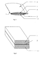
- fig. 1 and fig. 2 show flashing tape respectively before and after expanding
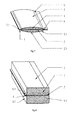
- fig. 3 and fig. 4 show this tape consisting of two stripes of compressible insulation foam separated by insulating tape also before and after expanding
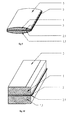
- fig. 5 and fig. 6 show the tape with perforation made on the side opposite to the protective film connection spot, again respectively before and after expanding
- fig. 7 and fig. 8 show the tape with two protective films connected with the stiffening tape on the edges at its both sides, before and after expanding
- still another example of the tape with two stiffening stripes joined on the edges with the protective film is shown on fig. 9 and fig. 10 of the drawing, respectively before and after the tape expanding according to the invention.
- fig. 11 shows the location of spots where the protective film is attached to stiffening tapes
- fig. 12 shows the connecting spots of the ready to use tape and place in which the tape is to be cut above the connecting spots
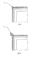
- Fig. 16 shows the section of an installed window with the flashing tape
- fig. 17 and fig. 18 show a view of the tape according to the invention placed in the corners, respectively wound up in a loop as on fig. 14 or cut to the gap length as shown on fig. 15 .
- the flashing tape consists of two stripes of compressible insulation foam (1) and (1.1) separated by a stiffening tape (2) compressed in a direction crosswise to the stiffening tape (2) and wrapped with protective film (3).
- Fig. 2 of the drawing shows the expanded flashing tape.
- the flashing tape consists of two stripes of compressible insulation foam (1) and (1.1) separated by a stiffening tape (2) compressed in a direction crosswise to the stiffening tape (2) and wrapped with protective film (3).
- the protective film (3) is connected with itself in spot (4). In a small distance from the spot where the film is joined (4) there are film perforations (5) and (5.1).
- Fig. 4 is an expansion of the view on fig. 3 , it, however, shows the expanded tape.
- FIG. 7 Another example of the flashing tape made according to the invention is presented on fig. 7 .
- the flashing tape in this version differs from the version presented on fig. 3 as in this case two protective films (3) and (3.1) are joined by the stiffening tape (2) on its edge on both sides (7) and (7.1).
- the protective films (3) and (3.1) are joined in spot (4), and in a small distance from the film connection spot (4) there are film perforations (5) and (5.1).
- Fig. 5 presents this tape expanded.
- the stiffening tape consists of two stripes (2) and (2.1) joined with the protective film (3).
- the protective film (3) is joined to the stiffening tapes (2) and (2.1) in spots (8) and (8.1).
- This connection is shown on fig. 11 .
- Two stripes of compressible foam (1) and (1.1) are fixed to the stiffening tapes (2) and (2.1).
- the stiffening tapes (2) and (2.1) are wound up to the inside, and then, as shown on fig. 14 the tape edges are joined in spot (9).
- the part of the tape located above the connection point (9) as shown on fig. 15 is cut in place (10).
- the stiffening tapes (2) and (2.1) are joined either on their entire surface (11) or on its part and they constitute a double-sided stiffening tape.
- Fig. 10 shows this type of the tape expanded.
- Fig. 16 is an illustration of the installed window section with expanded flashing tape, the tape installation in expansion gap is clearly shown.
- Fig. 17 and fig. 18 present the methods of flashing tapes installation in the corners.
- the tape may be wrapped in a corner in the form of a loop which is shown on fig. 13 or cut it in the corner adjusting its length to the length of the gap, which is presented on fig. 14 of the drawing.
- the flashing tape in version shown on fig. 1 consists of two stripes of compressible foam (1) and (1.1) separated by a stiffening tape (2) compressed in a direction crosswise to the stiffening tape by wrapping them with protective film (3).
- the compressible foam (1) and (1.1) may be made of any material having a foam structure allowing its compression, for example a polyurethane foam or polyurethane foam impregnated with acrylic glue slowing down its expansion and increasing its insulating power. It is also possible to use other type of plastic foams. Insulating tapes may also be of equal or different thicknesses. Their thickness depends on the expansion gap width.
- the stiffening tape (3) allows to obtain a tape of an ellipse like shape, which is a significant advantage as such tape may be used for insulation of gaps having a big ratio of the expansion gap depth to its width which for example is the case for an expansion gap between opening in the building and a window or door, where the ratio of the gap depth to its width is usually bigger than 2. It is advantageous to make the stiffening tape (2) from plastic.
- the stiffening tape (2) may be perforated or goffered which reduces its stiffness in longitudinal direction while maintaining the crosswise stiffness. Such solution is particularly advantageous as it allows for easier wrapping the tape in the corners.
- the stiffening tape (2) material may be for example a cardboard or paperboard.
- the protective film (3) made of plastic may also be made as a multilayer film and/or film containing reinforcing materials such as nonwoven fabric, knitted fabric or textile.
- a torn or cut protective film (3) may play the role of external insulation, it may be made of a vapour-permeable film or a film of variable permeability for water vapour depending on air humidity. Such film has a low vapour-permeability at low air humidity and high permeability at high air humidity.
- the use of protective film (3) for external insulation is particularly advantageous as it eliminates the necessity to apply additional external expansion tape.
- the connection (4) may be made by means of adhesion or welding. It is also possible to use a sleeve made for example of heat shrink plastic film. In this version, the expansion of foam (1) and (1.1) takes place by cutting the protective film (3).
- the flashing tape in the version presented on fig. 3 consists of two stripes of compressible insulation foam (1) and (1.1) separated by a stiffening tape (2) compressed in a direction crosswise to the stiffening tape (2) by wrapping with protective film (3).
- the protective film (3) may for example be joined on the spot (4) by gluing, sewing or welding. In a small distance from the spot (4) where the film (3) is joined there are film perforations (5) and (5.1) enabling tearing the protective film (3) off. It is also possible to tear the film (3) off using different methods, for example by means of a pull strip or thread melted into the film.
- connection there is a place (6), in which the protective film (3) is joined for example by gluing or welding to the edge of stiffening tape (2).
- This connection prevents movement of protective film (3) while it is being torn.
- the flashing tape without perforation. In such a case the tape is cut with a knife.
- Side edges of the insulating foams (1) and (1.1) from the side which after the tape installation in the gap between a window and wall is located inside the building may additionally be covered with a vapour barrier layer (12) or a layer of variable permeability for water vapour.
- This layer may for example be an impregnate or film of specific properties. It may also be an additional layer of compressible foam having the required properties.
- Such solution causes that it is not necessary to seal the connection between the window or door frame with the wall by means of an insulation tape.
- the following example of the tape version is illustrated on fig. 7 of the drawing.
- two protective films (3) and (3.1) are joined to the stiffening tape (2) on its edge on its both sides (7) and (7.1).
- the protective films (3) and (3.1) in the spot (4) in which they are joined may for example be glued, sewed or welded.
- film perforations (5) and (5.1) In a small distance from the spot (4) where the film (3) is joined there are film perforations (5) and (5.1) preventing tearing of the protective film (3) off. It is also possible to produce the tape according to this example without perforation. In such a case the tape is cut with a knife.
- Still another example of the flashing tape made according to the invention is a double-sided tape presented on fig. 9 .
- the stiffing tape consists of two stripes (2) and (2.1) joined with the protective film (3).
- the protective film (3) is attached to the stiffening tapes (2) and (2.1) in places (8) and (8.1), and this connection is shown on fig. 11 .
- Two stripes of compressible foam (1) and (1.1) are fixed to the stiffening tapes (2) and (2.1).
- the stiffening tapes (2) and (2.1) are wrapped to the inside and then, as shown on fig. 14 the tape edges are joined in point (9).
- Fig. 10 presents this version of the flashing tape after expanding.
- flashing tape enables easy and quick insulation and sealing of the gap, especially if the gap depth is bigger than its width.
- Such tape may be delivered in rolls of any length and widths adjusted to the gap width.
- the tape height may be adjusted to the gap width.
- the installation of the flashing tape is made by pushing it along the gap between the window or door frame, and then tearing of the protective film (3).
- the compressible foam (2) and (2.1) is then expanded.
- the finish works on frames may be immediately stared, for example by their plastering or covering with plasterboards.
Landscapes
- Engineering & Computer Science (AREA)
- Civil Engineering (AREA)
- Structural Engineering (AREA)
- Adhesive Tapes (AREA)
- Building Environments (AREA)
- Laminated Bodies (AREA)
Abstract
Description
- The subject of invention is a flashing tape, in particular to be used as a seal and insulation of the gap between window or door frame and a wall.
- A traditional method of joints insulation between an opening in the building wall and a window or door frame is injecting a polyurethane foam to the gap or filling such gap with some insulating material, for example mineral wool. Basic drawback of such solutions is that they are labour-consuming and the gap insulation is not homogenous. Another disadvantage of such solutions is the fact that apart from these materials which play the role of thermal insulation, such as foam, or wool, it is necessary to additionally apply expansion tapes performing the sealing role.
- There are also methods of sealing the joints between a window and wall by means of expanding tapes made of polyurethane foams impregnated with acrylic glue. This solution however, has a significant drawback as the window installation time with the tape must be limited to the tape expanding time which considerably limits the possibility to apply this solution in practice.
- The patent application no
DE199 44 611 describes a sealing stripe used as a seal of the gap consisting of a plastic tear-to-open sheath in which a foam stripe is placed. The drawback of such a seal stripe is that its shape is barrel-like. It prevents even placement of the stripe in a narrow gap, especially if the gap depth is bigger than its width. - The subject of the invention is a seal tape eliminating the aforementioned drawbacks.
- In basic version, the flashing tape consists of two stripes of compressible insulation foam separated by a stiffening tape compressed in a direction crosswise to the stiffening tape by being wrapped with protective film. The compressible foam may be made of any material having a foam structure allowing its compression, for example a polyurethane foam or polyurethane foam impregnated with acrylic glue slowing down its expansion and increasing its insulating power. It is also possible to use other types of plastic foams. Insulating tapes may also be of different thickness. This thickness depends on the width of expansion gap. The stiffening tape allows to obtain a tape of an ellipse like shape, which is a significant advantage as such tape may be used for insulation of gaps having a big ratio of the expansion gap depth to its width which for example is the case for an expansion gap between opening in the building and a window or door, where the ratio of the gap depth to its width is usually bigger than 2. It is advantageous to make the stiffening tape from plastic. The stiffening tape may be perforated or goffered which reduces its stiffness in longitudinal direction while maintaining the crosswise stiffness. Such solution is particularly advantageous as it allows for easier wrapping the tape in corners. The stiffening tape material may be for example a cardboard or paperboard. The protective film made of plastic may also be made as a multilayer film and/or film containing reinforcing materials such as nonwoven fabric, knitted fabric or textile. As a tom or cut protective film may play the role of external insulation, it may be made of a vapour-permeable film or a film of variable permeability for water vapour depending on air humidity. Such film has a low vapour-permeability at low air humidity and high permeability at high air humidity. The use of protective film for external insulation is particularly advantageous as it eliminates the necessity to apply additional external expansion tape. The connection of protective film may be made by means of adhesion or welding. It is also possible to use a sleeve made for example of heat shrink plastic film. In such version, the expansion of foam takes place by cutting the protective film.
- In another version, the flashing tape consists of two stripes of compressible insulation foam separated by a stiffening tape compressed in a direction crosswise to the stiffening tape by wrapping with protective film. The protective film may be joined for example by gluing, sewing or welding. In a small distance from the spot where the film is joined there are perforations enabling tearing the protective film off. It is also possible to tear the film using different methods, for example by means of a pull strip or thread melted into the film. On the opposite side of the spot of the protective film connection there is a place, in which the this film is joined for example by gluing or welding to the edge of stiffening tape. This connection prevents movement of protective film while it is being torn. It is also possible to make the flashing tape without perforation. In such a case the tape is cut with a knife. Side edges of the insulating foams from the side which after the tape installation in the gap between a window and wall is located inside the building may additionally be covered with a vapour barrier layer or a layer of variable permeability for water vapour. This layer may for example be an impregnate or film of specific properties. It may also be an additional layer of compressible foam having the required properties. Such solution causes that it is not necessary to seal the gap between the window or door frame and the wall by means of an insulation tape.
- In another version, the perforation is made on the side opposite to the spot where the film is joined. The tape expands after the sticking out film edges are pulled. In this version the protective film is removed completely.
- It is also possible to use two protective films which are joined to the stiffening tape on its edge on its both sides. On the opposite side, the protective films in the spot in which they are joined may be glued, sewed or welded, and in a small distance from the spot where the film is joined there are perforations preventing tearing protective films off. It is also possible to produce the tape according to this example without perforation. In such a case the tape is cut with a knife.
- Still another example of flashing tape is a double-sided tape. This version is particularly advantageous as the stiffing tape consisting of two stripes joined with the protective film allows for strong compression of the foam. Protective film is attached to the stiffening tapes and two stripes of compressible foam are fixed.
- The subject of the invention is presented in the manufacturing examples on a drawing on which
fig. 1 and fig. 2 show flashing tape respectively before and after expanding,fig. 3 and fig. 4 show this tape consisting of two stripes of compressible insulation foam separated by insulating tape also before and after expanding, whereasfig. 5 and fig. 6 show the tape with perforation made on the side opposite to the protective film connection spot, again respectively before and after expanding, thenfig. 7 and fig. 8 show the tape with two protective films connected with the stiffening tape on the edges at its both sides, before and after expanding, still another example of the tape with two stiffening stripes joined on the edges with the protective film is shown onfig. 9 and fig. 10 of the drawing, respectively before and after the tape expanding according to the invention. The location of spots where the protective film is attached to stiffening tapes is shown onfig. 11 of the drawing, whereas the connecting spots of the ready to use tape and place in which the tape is to be cut above the connecting spots are shown respectively onfig. 12 to fig. 15 of the drawing.Fig. 16 shows the section of an installed window with the flashing tape, andfig. 17 and fig. 18 show a view of the tape according to the invention placed in the corners, respectively wound up in a loop as onfig. 14 or cut to the gap length as shown onfig. 15 . - As shown on
fig. 1 of the drawing, the flashing tape consists of two stripes of compressible insulation foam (1) and (1.1) separated by a stiffening tape (2) compressed in a direction crosswise to the stiffening tape (2) and wrapped with protective film (3).Fig. 2 of the drawing shows the expanded flashing tape. - Another version of the double-sided flashing tape made according to the invention is shown on
fig. 3 . In this version, the flashing tape consists of two stripes of compressible insulation foam (1) and (1.1) separated by a stiffening tape (2) compressed in a direction crosswise to the stiffening tape (2) and wrapped with protective film (3). The protective film (3) is connected with itself in spot (4). In a small distance from the spot where the film is joined (4) there are film perforations (5) and (5.1). On the opposite side of the spot (4) of the protective film connection there is a place (6), in which the protective film (3) is joined to the edge of stiffening tape (2).Fig. 4 is an expansion of the view onfig. 3 , it, however, shows the expanded tape. - The following version of the tape as per the invention is presented on
fig. 5 of the drawing which shows the flashing tape differing from the one shown onfig. 3 by the fact that perforation (5) is located on the side opposite to the film connection (4).Fig. 6 presents this tape expanded. - Another example of the flashing tape made according to the invention is presented on
fig. 7 . The flashing tape in this version differs from the version presented onfig. 3 as in this case two protective films (3) and (3.1) are joined by the stiffening tape (2) on its edge on both sides (7) and (7.1). On the opposite side, the protective films (3) and (3.1) are joined in spot (4), and in a small distance from the film connection spot (4) there are film perforations (5) and (5.1).Fig. 5 presents this tape expanded. - Still another example of the flashing tape made according to the invention in a double-sided version is presented on
fig. 9 of the drawing. In this version, the stiffening tape consists of two stripes (2) and (2.1) joined with the protective film (3). The protective film (3) is joined to the stiffening tapes (2) and (2.1) in spots (8) and (8.1). This connection is shown onfig. 11 . Two stripes of compressible foam (1) and (1.1) are fixed to the stiffening tapes (2) and (2.1). Further, as shown onfigure 12 and figure 13 the stiffening tapes (2) and (2.1) are wound up to the inside, and then, as shown onfig. 14 the tape edges are joined in spot (9). The part of the tape located above the connection point (9) as shown onfig. 15 is cut in place (10). The stiffening tapes (2) and (2.1) are joined either on their entire surface (11) or on its part and they constitute a double-sided stiffening tape.Fig. 10 shows this type of the tape expanded. -
Fig. 16 is an illustration of the installed window section with expanded flashing tape, the tape installation in expansion gap is clearly shown. -
Fig. 17 and fig. 18 present the methods of flashing tapes installation in the corners. The tape may be wrapped in a corner in the form of a loop which is shown onfig. 13 or cut it in the corner adjusting its length to the length of the gap, which is presented onfig. 14 of the drawing. - The flashing tape in version shown on
fig. 1 consists of two stripes of compressible foam (1) and (1.1) separated by a stiffening tape (2) compressed in a direction crosswise to the stiffening tape by wrapping them with protective film (3). The compressible foam (1) and (1.1) may be made of any material having a foam structure allowing its compression, for example a polyurethane foam or polyurethane foam impregnated with acrylic glue slowing down its expansion and increasing its insulating power. It is also possible to use other type of plastic foams. Insulating tapes may also be of equal or different thicknesses. Their thickness depends on the expansion gap width. The stiffening tape (3) allows to obtain a tape of an ellipse like shape, which is a significant advantage as such tape may be used for insulation of gaps having a big ratio of the expansion gap depth to its width which for example is the case for an expansion gap between opening in the building and a window or door, where the ratio of the gap depth to its width is usually bigger than 2. It is advantageous to make the stiffening tape (2) from plastic. The stiffening tape (2) may be perforated or goffered which reduces its stiffness in longitudinal direction while maintaining the crosswise stiffness. Such solution is particularly advantageous as it allows for easier wrapping the tape in the corners. The stiffening tape (2) material may be for example a cardboard or paperboard. The protective film (3) made of plastic may also be made as a multilayer film and/or film containing reinforcing materials such as nonwoven fabric, knitted fabric or textile. As a torn or cut protective film (3) may play the role of external insulation, it may be made of a vapour-permeable film or a film of variable permeability for water vapour depending on air humidity. Such film has a low vapour-permeability at low air humidity and high permeability at high air humidity. The use of protective film (3) for external insulation is particularly advantageous as it eliminates the necessity to apply additional external expansion tape. In this version the connection (4) may be made by means of adhesion or welding. It is also possible to use a sleeve made for example of heat shrink plastic film. In this version, the expansion of foam (1) and (1.1) takes place by cutting the protective film (3). - The tape compliant with the description above is presented in expanded state on
fig. 2 of the drawing. - The flashing tape in the version presented on
fig. 3 consists of two stripes of compressible insulation foam (1) and (1.1) separated by a stiffening tape (2) compressed in a direction crosswise to the stiffening tape (2) by wrapping with protective film (3). The protective film (3) may for example be joined on the spot (4) by gluing, sewing or welding. In a small distance from the spot (4) where the film (3) is joined there are film perforations (5) and (5.1) enabling tearing the protective film (3) off. It is also possible to tear the film (3) off using different methods, for example by means of a pull strip or thread melted into the film. On the opposite side of the spot (4) of the film (3) connection there is a place (6), in which the protective film (3) is joined for example by gluing or welding to the edge of stiffening tape (2). This connection prevents movement of protective film (3) while it is being torn. It is also possible to produce the flashing tape without perforation. In such a case the tape is cut with a knife. Side edges of the insulating foams (1) and (1.1) from the side which after the tape installation in the gap between a window and wall is located inside the building may additionally be covered with a vapour barrier layer (12) or a layer of variable permeability for water vapour. This layer may for example be an impregnate or film of specific properties. It may also be an additional layer of compressible foam having the required properties. Such solution causes that it is not necessary to seal the connection between the window or door frame with the wall by means of an insulation tape. - Another example of the tape made according to the invention is presented on
fig. 5 of the drawing. In this case the perforation (5) is located on the side opposite to the spot (4) where the film (3) is joined. The tape expands after the sticking out film edges are pulled. In this version the protective film (4) is removed completely. - The following example of the tape version is illustrated on
fig. 7 of the drawing. In this version, two protective films (3) and (3.1) are joined to the stiffening tape (2) on its edge on its both sides (7) and (7.1). On the opposite side, the protective films (3) and (3.1) in the spot (4) in which they are joined may for example be glued, sewed or welded. In a small distance from the spot (4) where the film (3) is joined there are film perforations (5) and (5.1) preventing tearing of the protective film (3) off. It is also possible to produce the tape according to this example without perforation. In such a case the tape is cut with a knife. - Still another example of the flashing tape made according to the invention is a double-sided tape presented on
fig. 9 . In this version which is particularly advantageous as it allows for strong compression of the foam (2) the stiffing tape consists of two stripes (2) and (2.1) joined with the protective film (3). The protective film (3) is attached to the stiffening tapes (2) and (2.1) in places (8) and (8.1), and this connection is shown onfig. 11 . Two stripes of compressible foam (1) and (1.1) are fixed to the stiffening tapes (2) and (2.1). Then, as shown onfig. 12 and fig. 13 the stiffening tapes (2) and (2.1) are wrapped to the inside and then, as shown onfig. 14 the tape edges are joined in point (9). The part of the tape located above the connection point (9) as presented onfig. 15 is cut in place (10). The stiffening tapes (2) and (2.1) are joined either on their entire contiguous surface (11) or on its part and they constitute a double-sided stiffening tape. Such solution allows for easy adjustment of proper stress of the protective film (3) by proper selection of its width.Fig. 10 presents this version of the flashing tape after expanding. - The construction of flashing tape enables easy and quick insulation and sealing of the gap, especially if the gap depth is bigger than its width. Such tape may be delivered in rolls of any length and widths adjusted to the gap width. The tape height may be adjusted to the gap width.
- The installation of the flashing tape is made by pushing it along the gap between the window or door frame, and then tearing of the protective film (3). The compressible foam (2) and (2.1) is then expanded. After the tape installation, the finish works on frames may be immediately stared, for example by their plastering or covering with plasterboards.
Claims (26)
- Flashing tape is used as seal and insulation of the gap between window or door frame and a wall, consisting of expanding foam in a tear-to-open plastic sheath features that it consists of at least two stripes (1) and (1.1) of compressible insulation foam covered at least on one side with a vapour barrier layer (12) attached on two sides to the stiffening tape (2), these stripes (1) and ( 1.1 ) are compressed in the direction crosswise to the stiffening tape (2) be means of at least one protective film (3) with perforation (5) and (5.1), whereby the film (3) is joined to the edge of the stiffening tape (2) in connection places (6) or in places (7) and (7.1 ) in case it is made of two film stripes (3) and (3.1), whereby the protective film (3) is joined in spot (4).
- The tape according to claim 1 features that the stiffening tape (2) is made of plastic.
- The tape according to claim 1 features that the stiffening tape (2) is made of cardboard.
- The tape according to claim 1 features that the stiffening tape (2) is made of paperboard.
- The tape according to claim 1 features that the stiffening tape (2) is more flexible in the longitudinal direction than crosswise.
- The tape according to claim 1 features that the protective film (3) is welded in the connection place (4).
- The tape according to claim 1 features that the protective film (3) is glued in the connection place (4).
- The tape according to claim 1 features that the protective film (3) is sewn in the connection place (4).
- The tape according to claims 1 to 8 features that the stripes (1) and (1.1) of the compressible insulation foam are made of cell polyurethane foam.
- The tape according to claims 1 to 8 features that the stripes (1) and (1.1) of the compressible insulation foam are made of flexible polyurethane foam soaked in acrylic impregnate.
- The tape according to claims 1 to 10 features that the protective film (3) is joined to the edge of stiffening tape (2) in the connection spot (6) by welding.
- The tape according to claims 1 to 10 features that the protective film (3) is joined to the edge of stiffening tape (2) in the connection spot (6) by adhesion.
- The tape according to claims 1 to 10 features that the protective film (3) is joined to the edge of stiffening tape (2) in the connection spot (6) by welding.
- The tape according to claims 1 to 13 features that the vapour barrier layer (12) is made of impregnate.
- The tape according to claims 1 to 13 features that the vapour barrier layer (12) is made of plastic.
- The tape according to claims 1 to 13 features that the vapour barrier layer (12) is made of aluminium film.
- The tape according to claims 1 to 13 features that the protective film (3) is made of plastic.
- The tape according to claims 1 to 13 features that the protective film (3) is made of nonwoven fabric.
- The tape according to claims 1 to 13 features that the protective film (3) is made of textile.
- The tape according to claims 1 to 13 features that the protective film (3) is made of plastic combined with nonwoven fabric.
- The tape according to claims 1 to 13 features that the protective film (3) is made of plastic combined with knitted fabric.
- The tape according to claims 1 to 13 features that the protective film (3) is made of plastic combined with textile.
- The tape according to claims 1 to 13 features that the protective film (3) is made of plastic combined with paper.
- The tape according to claims 1 to 13 features that the protective film (3) is vapour-permeable.
- The tape according to claims 1 to 13 features that the protective film (3) is a film of variable permeability for water vapour, depending on air humidity.
- The production method of the flashing tape features that two stiffening tapes (2) and (2.1) are joined with the protective film (3) in places (8) and (8.1), two stripes (1) and (1.1) of compressible foam are fixed to the stiffening tapes (2) and(2.1), and then the stiffening tapes (2) and (2.1 ) are wrapped to the inside, and further the tape edges are joined in place (9) whereas the part of the tape above the connection place (9) is cut in place (10), whereby the stiffening tapes (2) and (2.1) are either joined on entire contiguous surface (11) or on its part.
Applications Claiming Priority (1)
| Application Number | Priority Date | Filing Date | Title |
|---|---|---|---|
| PL392106A PL216500B1 (en) | 2010-08-11 | 2010-08-11 | Sealing-insulating tape, especially for windows and doors and method for manufacturing the sealing-insulating tape |
Publications (2)
| Publication Number | Publication Date |
|---|---|
| EP2505759A2 true EP2505759A2 (en) | 2012-10-03 |
| EP2505759A3 EP2505759A3 (en) | 2014-11-12 |
Family
ID=45623100
Family Applications (1)
| Application Number | Title | Priority Date | Filing Date |
|---|---|---|---|
| EP11460041.4A Withdrawn EP2505759A3 (en) | 2010-08-11 | 2011-08-04 | Flashing tape, in particular for windows and doors and method of flashing tape production |
Country Status (2)
| Country | Link |
|---|---|
| EP (1) | EP2505759A3 (en) |
| PL (1) | PL216500B1 (en) |
Cited By (5)
| Publication number | Priority date | Publication date | Assignee | Title |
|---|---|---|---|---|
| EP2915931A1 (en) * | 2014-03-03 | 2015-09-09 | Keylite Roof Windows Limited | An insulation member |
| EP3366856A1 (en) * | 2017-02-22 | 2018-08-29 | HILTI Aktiengesellschaft | Fire protection sealing system |
| EP3540166A1 (en) * | 2018-03-16 | 2019-09-18 | Silu Verwaltung AG | Sealing strip |
| EP3578728A1 (en) * | 2018-06-05 | 2019-12-11 | VKR Holding A/S | Installation unit for facilitating the installation of a window frame, a sealing collar, and a method for installing a window frame in an open-ing in a roof structure |
| CH716563A1 (en) * | 2019-09-05 | 2021-03-15 | Silu Verwaltung Ag | Sealing strips for sealing joints, preferably in the construction sector, in particular for sealing joints between a window or door and masonry. |
Citations (1)
| Publication number | Priority date | Publication date | Assignee | Title |
|---|---|---|---|---|
| DE19944611A1 (en) | 1999-09-17 | 2001-03-22 | Illbruck Gmbh | Sealing strips for sealing a joint |
Family Cites Families (2)
| Publication number | Priority date | Publication date | Assignee | Title |
|---|---|---|---|---|
| SE9701292D0 (en) * | 1997-04-09 | 1997-04-09 | Johan Stroemberg | Sealing strip between two structural parts |
| EP2138664B1 (en) * | 2008-06-23 | 2015-04-15 | ISO-Chemie GmbH | Precompressed sealing tape |
-
2010
- 2010-08-11 PL PL392106A patent/PL216500B1/en unknown
-
2011
- 2011-08-04 EP EP11460041.4A patent/EP2505759A3/en not_active Withdrawn
Patent Citations (1)
| Publication number | Priority date | Publication date | Assignee | Title |
|---|---|---|---|---|
| DE19944611A1 (en) | 1999-09-17 | 2001-03-22 | Illbruck Gmbh | Sealing strips for sealing a joint |
Cited By (7)
| Publication number | Priority date | Publication date | Assignee | Title |
|---|---|---|---|---|
| EP2915931A1 (en) * | 2014-03-03 | 2015-09-09 | Keylite Roof Windows Limited | An insulation member |
| EP3366856A1 (en) * | 2017-02-22 | 2018-08-29 | HILTI Aktiengesellschaft | Fire protection sealing system |
| EP3540166A1 (en) * | 2018-03-16 | 2019-09-18 | Silu Verwaltung AG | Sealing strip |
| WO2019175418A1 (en) * | 2018-03-16 | 2019-09-19 | Silu Verwaltung Ag | Sealing strip |
| EP3540166B1 (en) | 2018-03-16 | 2025-02-26 | Silu Verwaltung AG | Sealing strip |
| EP3578728A1 (en) * | 2018-06-05 | 2019-12-11 | VKR Holding A/S | Installation unit for facilitating the installation of a window frame, a sealing collar, and a method for installing a window frame in an open-ing in a roof structure |
| CH716563A1 (en) * | 2019-09-05 | 2021-03-15 | Silu Verwaltung Ag | Sealing strips for sealing joints, preferably in the construction sector, in particular for sealing joints between a window or door and masonry. |
Also Published As
| Publication number | Publication date |
|---|---|
| PL216500B1 (en) | 2014-04-30 |
| EP2505759A3 (en) | 2014-11-12 |
| PL392106A1 (en) | 2012-02-13 |
Similar Documents
| Publication | Publication Date | Title |
|---|---|---|
| US8317200B2 (en) | Precompressed sealing tape | |
| US8241721B2 (en) | Re-expandable sealing tape | |
| US8318280B2 (en) | Sealing tape of soft foam and method for its production | |
| US11591790B2 (en) | Sealing tape for sealing a joint | |
| US20130187348A1 (en) | Sealing Tape for Sealing a Joint | |
| EP2505759A2 (en) | Flashing tape, in particular for windows and doors and method of flashing tape production | |
| US8541084B2 (en) | Sealing tape | |
| US6141930A (en) | Method of and article for insulating standard and nonstandard cavities and an insulated structure | |
| EP2333177B1 (en) | Precompressed sealing tape | |
| US3979537A (en) | Insulating material and methods of manufacture | |
| US7780886B2 (en) | Insulation product having directional facing layer thereon and method of making the same | |
| US8695309B2 (en) | Method for sealing of replacement windows | |
| PL204357B1 (en) | Sealing strip for sealing a joint | |
| NO339993B1 (en) | Soft foam sealing tape | |
| US11014345B2 (en) | Method for producing sealing tape rolls | |
| US10286624B2 (en) | Sealing tape roll | |
| US20140193602A1 (en) | Precompressed Sealing Tape | |
| US10072420B2 (en) | Insulation member | |
| KR200321622Y1 (en) | dampproof seat for floor | |
| JP2021038514A (en) | Interior panel and method for manufacturing interior panel | |
| US20050249908A1 (en) | Vapor retarding film and folding thereof | |
| EP2915931A1 (en) | An insulation member | |
| JP3599170B2 (en) | High thermal insulation structure and thermal insulation panel used in it | |
| KR102002598B1 (en) | Sealing tape roll with side coating | |
| KR20230001702U (en) | A lining sheet used for gypsum board joint |
Legal Events
| Date | Code | Title | Description |
|---|---|---|---|
| PUAI | Public reference made under article 153(3) epc to a published international application that has entered the european phase |
Free format text: ORIGINAL CODE: 0009012 |
|
| AK | Designated contracting states |
Kind code of ref document: A2 Designated state(s): AL AT BE BG CH CY CZ DE DK EE ES FI FR GB GR HR HU IE IS IT LI LT LU LV MC MK MT NL NO PL PT RO RS SE SI SK SM TR |
|
| AX | Request for extension of the european patent |
Extension state: BA ME |
|
| PUAL | Search report despatched |
Free format text: ORIGINAL CODE: 0009013 |
|
| AK | Designated contracting states |
Kind code of ref document: A3 Designated state(s): AL AT BE BG CH CY CZ DE DK EE ES FI FR GB GR HR HU IE IS IT LI LT LU LV MC MK MT NL NO PL PT RO RS SE SI SK SM TR |
|
| AX | Request for extension of the european patent |
Extension state: BA ME |
|
| RIC1 | Information provided on ipc code assigned before grant |
Ipc: E06B 1/62 20060101AFI20141003BHEP |
|
| STAA | Information on the status of an ep patent application or granted ep patent |
Free format text: STATUS: THE APPLICATION IS DEEMED TO BE WITHDRAWN |
|
| 18D | Application deemed to be withdrawn |
Effective date: 20150303 |