EP2505472A2 - Accelerator-opening-degree detection device for vehicle - Google Patents
Accelerator-opening-degree detection device for vehicle Download PDFInfo
- Publication number
- EP2505472A2 EP2505472A2 EP12161070A EP12161070A EP2505472A2 EP 2505472 A2 EP2505472 A2 EP 2505472A2 EP 12161070 A EP12161070 A EP 12161070A EP 12161070 A EP12161070 A EP 12161070A EP 2505472 A2 EP2505472 A2 EP 2505472A2
- Authority
- EP
- European Patent Office
- Prior art keywords
- spring
- accelerator
- rotor
- opening
- sensor case
- Prior art date
- Legal status (The legal status is an assumption and is not a legal conclusion. Google has not performed a legal analysis and makes no representation as to the accuracy of the status listed.)
- Granted
Links
Images


Classifications
-
- B—PERFORMING OPERATIONS; TRANSPORTING
- B62—LAND VEHICLES FOR TRAVELLING OTHERWISE THAN ON RAILS
- B62K—CYCLES; CYCLE FRAMES; CYCLE STEERING DEVICES; RIDER-OPERATED TERMINAL CONTROLS SPECIALLY ADAPTED FOR CYCLES; CYCLE AXLE SUSPENSIONS; CYCLE SIDE-CARS, FORECARS, OR THE LIKE
- B62K23/00—Rider-operated controls specially adapted for cycles, i.e. means for initiating control operations, e.g. levers, grips
- B62K23/02—Rider-operated controls specially adapted for cycles, i.e. means for initiating control operations, e.g. levers, grips hand actuated
- B62K23/04—Twist grips
-
- B—PERFORMING OPERATIONS; TRANSPORTING
- B62—LAND VEHICLES FOR TRAVELLING OTHERWISE THAN ON RAILS
- B62J—CYCLE SADDLES OR SEATS; AUXILIARY DEVICES OR ACCESSORIES SPECIALLY ADAPTED TO CYCLES AND NOT OTHERWISE PROVIDED FOR, e.g. ARTICLE CARRIERS OR CYCLE PROTECTORS
- B62J45/00—Electrical equipment arrangements specially adapted for use as accessories on cycles, not otherwise provided for
- B62J45/40—Sensor arrangements; Mounting thereof
- B62J45/41—Sensor arrangements; Mounting thereof characterised by the type of sensor
- B62J45/413—Rotation sensors
-
- B—PERFORMING OPERATIONS; TRANSPORTING
- B62—LAND VEHICLES FOR TRAVELLING OTHERWISE THAN ON RAILS
- B62J—CYCLE SADDLES OR SEATS; AUXILIARY DEVICES OR ACCESSORIES SPECIALLY ADAPTED TO CYCLES AND NOT OTHERWISE PROVIDED FOR, e.g. ARTICLE CARRIERS OR CYCLE PROTECTORS
- B62J45/00—Electrical equipment arrangements specially adapted for use as accessories on cycles, not otherwise provided for
- B62J45/40—Sensor arrangements; Mounting thereof
- B62J45/42—Sensor arrangements; Mounting thereof characterised by mounting
- B62J45/422—Sensor arrangements; Mounting thereof characterised by mounting on the handlebar
Definitions
- the present invention relates to an improvement of an accelerator-opening-degree detection device for a vehicle, including: a sensor case fixed to a bar-shaped steering handle; a rotor arranged adjacent to the sensor case, the rotor being coupled with an accelerator grip rotatably provided to the steering handle; an accelerator-opening-degree sensor accommodated and held in the sensor case, the accelerator-opening-degree sensor configured to detect a rotation angle from an initial position of the rotor; and a return spring connected to and between the sensor case and the rotor, the return spring configured to urge the rotor toward the initial position
- Such an accelerator-opening-degree detection device for a vehicle is already known as disclosed in Japanese Patent Application Laid-open No. 2004-339945 .
- the accelerator-opening-degree sensor upon detection of an opening degree of the accelerator grip, the accelerator-opening-degree sensor outputs a detection signal corresponding to the opening degree to an electronic control unit of a vehicle.
- the electronic control unit controls electric throttle valve of an engine, fuel injection amount of fuel injection valve, and ignition timing of ignition device.
- the accelerator-opening-degree detection device for a vehicle is required to generate a hysteresis in operation load, making a difference in operation load between an opening operation and a closing operation of the accelerator grip.
- the accelerator-opening-degree detection device for a vehicle described in Japanese Patent Application Laid-open No. 2004-339945 uses a spiral spring as a return spring configured to urge a rotor in a closing direction of the accelerator grip. With the rotation of the accelerator grip in an opening direction to wind up the spiral spring, portions of a resilient belt-shaped plate of the spiral spring come into friction contact with each other, which generates the hysteresis in operation load as described above due to friction resistance.
- the spiral spring is in an expanded state in which no portions of the resilient belt-shaped plate are in contact with each other. For this reason, desired hysteresis characteristic cannot be obtained. Thus, obtaining a favorable acceleration operation feeling at any position over the entire operating range of the accelerator grip is difficult.
- the present invention has been made in view of these circumstances.
- An object thereof is to provide a simple-structure accelerator-opening-degree detection device for a vehicle by which a favorable acceleration operation feeling can be obtained over the entire operating range in an accelerator grip while special-hysteresis-generation-means is not provided.
- an accelerator-opening-degree detection device for a vehicle, including: a sensor case fixed to a bar-shaped steering handle; a rotor arranged adjacent to the sensor case, the rotor being coupled with an accelerator grip rotatably provided to the steering handle; an accelerator-opening-degree sensor accommodated and held in the sensor case, the accelerator-opening-degree sensor configured to detect a rotation angle from an initial position of the rotor; and a return spring connected to and between the sensor case and the rotor, the return spring configured to urge the rotor toward the initial position, characterized in that an annular spring-accommodating groove surrounding the steering handle is formed in the sensor case, a spiral spring formed by winding a resilient belt-shaped plate a plurality of times is accommodated in the spring-accommodating groove, and in order to form the return spring by the spiral spring, an end of the spiral spring on an outer periphery and an end thereof on an inner periphery
- the spiral spring in the narrow portion of the spring-accommodating groove formed in the sensor case, the spiral spring is held in a state where portions of the resilient belt-shaped plates are stacked to be always in sliding contact with each other.
- friction resistance by the spiral spring is generated in the narrow portion of the spring-accommodating groove.
- the accelerator-opening-degree sensor is arranged inward of the spiral spring in a radial direction thereof.
- the accelerator-opening-degree sensor is arranged inward of the spiral spring in the radial direction thereof. Therefore, the sensor case and further the accelerator-opening-degree detection device can be made compact.
- an accelerator-opening-degree detection device for a vehicle, including: a sensor case fixed to a bar-shaped steering handle; a rotor arranged adjacent to the sensor case, the rotor being coupled with an accelerator grip rotatably provided to the steering handle; an accelerator-opening-degree sensor accommodated and held in the sensor case, the accelerator-opening-degree sensor configured to detect a rotation angle from an initial position of the rotor; and a return spring connected to and between the sensor case and the rotor, the return spring configured to urge the rotor toward the initial position, characterized in that an arc-shaped spring-accommodating groove having one end face serving as a fixed spring seat is formed in the sensor case, a movable spring seat protruding into the spring-accommodating groove and being capable of rotationally moving in the spring-accommodating groove is formed in the rotor, the return spring is formed by a wave spring or a coil spring which is provided in a compressed state
- the return spring formed by the wave spring or the coil spring is always in pressure contact with the inner surface of the arc-shaped spring-accommodating groove of the sensor case.
- the hysteresis characteristic can be obtained with the wave spring or the coil spring itself which forms the return spring, there is no need for special-hysteresis-generation-means, and the structure of the accelerator-opening-degree detection device can be simplified.
- the rotor comprises a flange closing an opening end of the sensor case, a case cover is formed by a holding wall and an outer tube, an outer side surface of the flange being held by the holding wall, the outer tube continuously provided to an outer peripheral end of the holding wall and fitted on an outer peripheral surface of the sensor case, and locking portions to be snapped into engagement with each other to couple the case cover and the sensor case together are provided to the outer tube and the sensor case, respectively.
- the accelerator-opening-degree detection device formed in such a manner that the rotor is rotatably accommodated in the inner space between the sensor case and the case cover can be formed into an assembly.
- the accelerator-opening-degree detection device can be attached to the steering handle at a time.
- a switch case is fitted to the steering handle to be adjacent to an inner end side of the accelerator grip, and is divided into a pair of case halves along a radial direction of the steering handle, the case halves are bolted together and fixedly attached to the steering handle, the sensor case and the rotor are accommodated in the switch case, and a positioning protrusion and a positioning hole which are engaged with each other to hinder the sensor case from rotating are provided to the sensor case and the switch case, respectively.
- the accelerator-opening-degree detection device is accommodated in the switch case fixedly attached to the steering handle, damage to the accelerator-opening-degree detection device due to contact with another object can be prevented.
- the switch case is divided into the pair of case halves along the radial direction of the steering handle, the accommodating of the accelerator-opening-degree detection device in the switch case can be performed easily.
- the positioning protrusion and the positioning hole respectively formed on the sensor case and in the switching case are engaged with each other to hinder the sensor case from rotating. Thus, the rotation prevention of the sensor case can be easily performed.
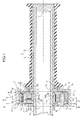
- FIG. 1 is a longitudinal cross-sectional view (a sectional view taken along a line 1-1 in FIG. 3 ) of an accelerator-opening-degree detection device according to a first embodiment of the present invention
- FIG. 2 is a sectional view taken along a line 2-2 in FIG. 1
- FIG. 3 is a sectional view taken along a line 3-3 in FIG. 1
- FIG. 4 is a view corresponding to FIG. 3 that shows a second embodiment of the present invention.
- FIG. 1 to FIG. 3 First, a first embodiment of the present invention shown in FIG. 1 to FIG. 3 will be described below.
- an accelerator grip G and a switch case 1 are attached to a right end portion of a bar-shaped steering handle H of a two-wheeled motor vehicle, the switch case 1 being adjacent to an inner end of this accelerator grip G.
- switches such as a starter switch and an engine kill switch are attached to the switch case 1, although the switches are not illustrated.
- the accelerator grip G includes a grip pipe 2 rotatably fitted on the steering handle H and a grip rubber 3 attached to an outer periphery of the grip pipe 2.
- a closure body 4 for preventing the grip pipe 2 from coming off the steering handle H is pressed to fit into an outer end of the steering handle H.
- the switch case 1 comprises an upper case half 1a and a lower case half 1b obtained by dividing in a diameter direction of the steering handle H. Both the upper and lower case halves 1a, 1b are mutually coupled by using bolts 8, 8 to sandwich the steering handle H and are thereby fixed to the steering handle H.
- An accelerator-opening-degree detection device D is provided inside the switch case 1, the accelerator-opening-degree detection device D being configured to detect a rotation angle of the accelerator grip G, that is, a degree of accelerator opening when the accelerator grip G is rotated from a fully-closed position toward a fully-opened position.
- the accelerator-opening-degree detection device D includes: a sensor case 5; a rotor 6 connected to the grip pipe 2 and rotatably supported by the sensor case 5; and a case cover 7 connecting the sensor case 5 and the rotor 6 together while allowing rotation of the rotor 6.
- the sensor case 5, the rotor 6, and the case cover 7 are all made of a synthesis resin.
- the sensor case 5 is formed by integrally molding: a cylindrical hub 5a whose inner periphery is fitted on an outer periphery of the steering handle H; a cylindrical case tube 5b which concentrically surrounds the hub 5a; and a side wall 5c integrally connecting an end portion of the hub 5a and an end portion of the case tube 5b together.
- a positioning protrusion 10 is integrally provided on an outer surface of the side wall 5c in such a manner as to protrude therefrom. Fitting the positioning protrusion 10 in a positioning hole 11 provided in the switch case 1 prevents the sensor case 5 from rotating around the steering handle H.
- an annular spring-accommodating groove 12 is defined between the hub 5a and the case tube 5b surrounding the hub 5a.
- a thick portion 5a1 is formed on the hub 5a on one substantially half peripheral side, while a thin portion 5a2 thinner than the thick portion 5a1 is formed on the other substantially half peripheral side.
- the thick portion 5a1 is formed in such a manner that the thickness thereof is increased toward the center portion, of the thick portion 5a1, in a peripheral direction.
- the spring-accommodating groove 12 has a narrow portion 12a having the narrowest groove width due to the center portion, of the thick portion 5a1, in the peripheral direction.
- a recessed portion 13 for sensor attachment is provided in an end face, of the thick portion 5a1, on an opposite side from the rotor 6, while a guide groove 14 which is concentric with the steering handle H and extending almost 180 degrees is provided in an end face, of the thick portion 5a1, on the rotor 6 side.
- the rotor 6 is formed by integrally molding: a hub 6a having an inner peripheral surface which has a step and is rotatably fitted on the outer peripheral surfaces of the steering handle H and the hub 5a; and a flange 6b extending from the hub 6a in a radial direction thereof.
- An arc-shaped movable protrusion 15 capable of rotationally moving in the guide groove 14 is integrally provided on an inner side surface of the flange 6b in a projecting manner.
- the flange 6b is rotatably engaged with an annular positioning step portion 16 formed on an opening end portion of the case tube 5b, thereby closing an opening end of the case tube 5b.
- An inner end portion of the grip pipe 2 is loosely fitted to the outer periphery of the hub 6a with a spline 17 placed in between.
- the rotation angle, of the rotor 6, which defines the rotation angle between the fully-closed position of the accelerator grip G and the fully-opened position thereof is limited to a range from a contact position between the movable protrusion 15 of the rotor 6 and one inner end face 14a of the guide groove 14 of the sensor case 5 to a contact position between the movable protrusion 15 and the other inner end face 14b.
- An illustrated example shows the rotation angle of a slightly smaller than 90 degrees.
- the case cover 7 is formed by integrally molding: a holding wall 7a in contact with an outer side surface of the flange 6b; and an outer tube 7b extending to form a cylindrical shape from an outer peripheral end of the holding wall 7a and fitted on an outer peripheral surface of the sensor case 5.
- the outer tube 7b has multiple locking claws 18 in a tip end portion of the outer tube 7b.
- the locking claws 18 protrude inward in a radial direction of the outer tube 7b and are arranged in a peripheral direction thereof.
- the locking claws 18 are snapped into engagement with multiple locking recess portions 19 formed in the outer periphery of the sensor case 5, and thereby the case cover 7 is fixed onto the sensor case 5. In this state, the holding wall 7a of the case cover 7 does not hinder the rotation of the flange 6b of the rotor 6.
- the annular spring-accommodating groove 12 accommodates a spiral spring 20 formed by coiling a resilient belt-shaped plate multiple times.
- the spiral spring 20 is held in the narrow portion 12a in a state where multiple portions of the resilient belt-shaped plate are stacked to slidingly contact with each other.
- the spiral spring 20 includes a fixing hook 20a on an end thereof on an outer periphery and a movable hook 20b on an end thereof on an inner periphery.
- the fixing hook 20a is engaged with an engaging hole 21 provided in the case tube 5b of the sensor case 5.
- the movable hook 20b is engaged with an engaging protrusion 22 protruding from the inner side surface of the flange 6b of the rotor 6.
- setting load in an extension direction is provided to the spiral spring 20 to urge the rotor 6 in the closing direction of the accelerator grip G, so that the spiral spring 20 serves as a return spring.
- the spiral spring 20 is designed to be wound up when the accelerator grip G is rotated in the opening direction.
- a magnet 24 is embedded in the movable protrusion 15 of the rotor 6 by insertion molding. While an accelerator-opening-degree sensor 25 by which a rotation angle of the magnet 24 rotating together with the rotor 6 is detected as an opening degree of the accelerator grip G is accommodated in the recessed portion 13 for sensor attachment of the sensor case 5, a sealing resin 28 for fixing the accelerator-opening-degree sensor 25 is filled into the recessed portion 13 for sensor attachment.
- the accelerator-opening-degree sensor 25 includes hall elements 26, 26 and a sensor circuit board 27 configured to convert output voltages from the hall elements 26, 26 into acceleration-opening-degree signals and to output the signals to an unillustrated electronic control unit of the two-wheeled motor vehicle. In this manner, the accelerator-opening-degree sensor 25 and the magnet 24 are arranged inward of the spiral spring 20 in a radial direction thereof.
- the rotor 6 When the accelerator grip G is rotated from the fully-closed position toward the full-opened position, the rotor 6 is also rotated together with the accelerator grip G, accompanying the magnet 24.
- the output voltages from the hall elements 26, 26 of the accelerator-opening-degree sensor 25 provided to the sensor case 5 are changed in accordance with the change of the rotation angle of the magnet 24, and the sensor circuit board 27 converts the changes of the output voltages from the hall elements 26, 26 into signals and outputs the signals to the unillustrated electronic control unit.
- the electronic control unit having received the signals controls operations of an electric throttle valve, a fuel injection valve, an ignition device, and the like of an engine in the same manner as in the conventional manner.
- the spiral spring 20 is wound up and concurrently increases a repulsive force.
- the spiral spring 20 is held in the narrow portion 12a of the spring-accommodating groove 12 accommodating the spiral spring 20, in the state where multiple portions of the resilient belt-shaped plate of the spiral spring 20 are stacked to be always in sliding contact with each other.
- friction resistance of the spiral spring 20 is generated in the narrow portion 12a.
- the hysteresis characteristic can be obtained in this manner with the spiral spring 20, itself, that is, the return spring, there is no need for special-hysteresis-generation-means, and the structure of the accelerator-opening-degree detection device D can be simplified.
- the accelerator-opening-degree sensor 25 including the hall elements 26, 26 and the sensor circuit board 27 and the magnet 24 are arranged in a dead space inward of the spiral spring 20 in the radial direction, which provides favorable efficiency of using space in the sensor case 5.
- the sensor case 5 and further the accelerator-opening-degree detection device D can be made compact.
- the spiral spring 20 is accommodated in the sensor case 5, and thereafter the opening end of the sensor case 5 is closed with the flange 6b of the rotor 6.
- the case cover 7 is fitted on the outer peripheral surface of the sensor case 5, and then the outer side surface of the flange 6b of the rotor 6 is held by the holding wall 7a of the case cover 7.
- the locking claws 18 of the case cover 7 are snapped into engagement with the locking recess portions 19 of the sensor case 5, and thereby the accelerator-opening-degree detection device D formed in such a manner that the rotor 6 is rotatably accommodated in the inner space between the sensor case 5 and the case cover 7 can be formed into an assembly.
- the accelerator-opening-degree detection device D can be attached to the steering handle H at a time.
- the accelerator-opening-degree detection device D is accommodated in the switch case 1 fixedly attached to the steering handle H, damage to the accelerator-opening-degree detection device D due to contact with another object can be prevented.
- the switch case 1 is divided into the pair of case halves 1a, 1b in the radial direction of the steering handle H, and the case halves 1a, 1b are fixedly attached to the steering handle H while being bolted together.
- the accommodating of the accelerator-opening-degree detection device D in the switch case 1 can be performed easily.
- the switch case 1 and the sensor case 5 are respectively provided with the positioning hole 11 and the positioning protrusion 10 which are engaged with each other to hinder the sensor case 5 from rotating.
- the rotation prevention of the sensor case 5 can be easily performed.
- the guide groove 14 and a spring-accommodating groove 30 are defined between the hub 5a and the case tube 5b of the sensor case 5.
- the guide groove 14 and the spring-accommodating groove 30 are arc-shaped and opposed to each other with a diameter line of the sensor case 5 located in between.
- the hub 5a and the case tube 5b are integrally joined by a pair of partition walls 5d, 5e shared with the arc-shaped guide groove 14 and the spring-accommodating groove 30.
- the movable protrusion 15 of the rotor 6 is arranged in the guide groove 14 in the same manner as in the former embodiment.
- a fixed spring seat 30a is formed on one end face of the spring-accommodating groove 30.
- a protrusive movable spring seat 33 protruding into the arc-shaped spring-accommodating groove 30 is formed in the rotor 6 in such a manner as to be opposed to the fixed spring seat 30a.
- a wave spring 32 provided in a compressed state is accommodated as a return spring between the fixed spring seat 30a and the movable spring seat 33.
- the wave spring 32 is curved in arc due to the arc-shaped spring-accommodating groove 30, and thereby an outer peripheral surface of the wave spring 32 is always in pressure contact with an inner side surface, of the arc-shaped spring-accommodating groove 30, on the outer peripheral side.
- the accelerator-opening-degree sensor 25 and the magnet 24 are arranged on the opposite side from the arc-shaped spring-accommodating groove 30 across the center of the sensor case 5.
- the wave spring 32 serving as the return spring is always in pressure contact with the inner side surface of the arc-shaped spring-accommodating groove 30 on the outer peripheral side.
- friction resistance is generated between the wave spring 32 and the inner side surface of the arc-shaped spring-accommodating groove 30 on the outer peripheral side.
- the hysteresis characteristic can be obtained with the wave spring 32 itself, that is, the return spring also in the second embodiment, there is no need for spccial-hysteresis-generation-means, and the structure of the accelerator-opening-degree detection device D can be simplified.
- the present invention is not limited to the aforementioned embodiments, and various design changes can be made without departing from the gist of the present invention.
- the pair of the hall elements 26 are provided to enhance the reliability of the accelerator-opening-degree sensor 25.
- a single hall element 26 may be provided.
- the present invention is applicable to a vehicle other than the two-wheeled motor vehicle as long as the vehicle is provided with a bar-shaped steering handle.
- the present application is applicable to an electric vehicle.
- An accelerator-opening-degree detection device for a vehicle includes: a sensor case (5) fixed to a bar-shaped steering handle (H); a rotor (6) arranged adjacent to the sensor case (5), the rotor being coupled with an accelerator grip (G); an accelerator-opening-degree sensor (25) accommodated and held in the sensor case (5), the accelerator-opening-degree sensor configured to detect a rotation angle of the rotor (6); and a return spring configured to urge the rotor (6) toward an initial position.
- a spiral spring (20) is accommodated in an annular spring-accommodating groove (12) formed in the sensor case (5).
- an end of the spiral spring (20) on an outer periphery and an end thereof on an inner periphery are respectively locked with the sensor case (5) and the rotor (6), and a narrow portion (12a) is provided in the spring-accommodating groove (12), a resilient belt-shaped plate of the spiral spring (20) being held in the narrow portion (12a) in a state where portions of the resilient belt-shaped plate in the narrow portion (12a) are stacked to be always in slidable contact with each other. Accordingly, it is possible to obtain a favorable acceleration operation feeling over the entire operating range of an accelerator grip while special-hysteresis-generation-means is not provided.
Landscapes
- Engineering & Computer Science (AREA)
- Mechanical Engineering (AREA)
- Control Of Throttle Valves Provided In The Intake System Or In The Exhaust System (AREA)
- Steering Devices For Bicycles And Motorcycles (AREA)
- Soil Working Implements (AREA)
- Auxiliary Drives, Propulsion Controls, And Safety Devices (AREA)
Abstract
Description
- The present invention relates to an improvement of an accelerator-opening-degree detection device for a vehicle, including: a sensor case fixed to a bar-shaped steering handle; a rotor arranged adjacent to the sensor case, the rotor being coupled with an accelerator grip rotatably provided to the steering handle; an accelerator-opening-degree sensor accommodated and held in the sensor case, the accelerator-opening-degree sensor configured to detect a rotation angle from an initial position of the rotor; and a return spring connected to and between the sensor case and the rotor, the return spring configured to urge the rotor toward the initial position
- Such an accelerator-opening-degree detection device for a vehicle is already known as disclosed in Japanese Patent Application Laid-open No.
2004-339945 - Meanwhile, in order to obtain a favorable feeling of operating the accelerator grip, the accelerator-opening-degree detection device for a vehicle is required to generate a hysteresis in operation load, making a difference in operation load between an opening operation and a closing operation of the accelerator grip. Hence, the accelerator-opening-degree detection device for a vehicle described in Japanese Patent Application Laid-open No.
2004-339945 - Since the return spring itself provides the hysteresis characteristic in such an accelerator-opening-degree detection device, special-hysteresis-generation-means is not needed for generating the hysteresis characteristic, and the structure of the accelerator-opening-degree detection device could be simplified.
- However, at or near a fully-closed position of the accelerator grip, the spiral spring is in an expanded state in which no portions of the resilient belt-shaped plate are in contact with each other. For this reason, desired hysteresis characteristic cannot be obtained. Thus, obtaining a favorable acceleration operation feeling at any position over the entire operating range of the accelerator grip is difficult.
- The present invention has been made in view of these circumstances. An object thereof is to provide a simple-structure accelerator-opening-degree detection device for a vehicle by which a favorable acceleration operation feeling can be obtained over the entire operating range in an accelerator grip while special-hysteresis-generation-means is not provided.
- In order to achieve the object, according to a first feature of the present invention, there is provided an accelerator-opening-degree detection device for a vehicle, including: a sensor case fixed to a bar-shaped steering handle; a rotor arranged adjacent to the sensor case, the rotor being coupled with an accelerator grip rotatably provided to the steering handle; an accelerator-opening-degree sensor accommodated and held in the sensor case, the accelerator-opening-degree sensor configured to detect a rotation angle from an initial position of the rotor; and a return spring connected to and between the sensor case and the rotor, the return spring configured to urge the rotor toward the initial position, characterized in that an annular spring-accommodating groove surrounding the steering handle is formed in the sensor case, a spiral spring formed by winding a resilient belt-shaped plate a plurality of times is accommodated in the spring-accommodating groove, and in order to form the return spring by the spiral spring, an end of the spiral spring on an outer periphery and an end thereof on an inner periphery are respectively locked with the sensor case and the rotor, and a narrow portion is provided in the spring-accommodating groove, the resilient belt-shaped plate of the spiral spring being held in the narrow portion in a state where portions of the resilient belt-shaped plate in the narrow portion are stacked to be always in slidable contact with each other.
- According to the first feature of the present invention, in the narrow portion of the spring-accommodating groove formed in the sensor case, the spiral spring is held in a state where portions of the resilient belt-shaped plates are stacked to be always in sliding contact with each other. Thus, wherever the accelerator grip angle is set in the operating range from a fully-closed position to a fully-opened position, friction resistance by the spiral spring is generated in the narrow portion of the spring-accommodating groove. Thereby, a difference in operation load between an opening operation and a closing operation of the accelerator grip is obtained as the hysteresis characteristic, which can always provide a favorable operation feeling of the accelerator grip. Moreover, since the hysteresis characteristic can be obtained in this manner with the spiral spring itself forming the return spring, there is no need for special-hysteresis-generation-means, and the structure of the accelerator-opening-degree detection device can be simplified.
- Further, according to a second feature of the present invention, in addition to the first feature, the accelerator-opening-degree sensor is arranged inward of the spiral spring in a radial direction thereof.
- According to the second feature of the present invention, the accelerator-opening-degree sensor is arranged inward of the spiral spring in the radial direction thereof. Thereby, the sensor case and further the accelerator-opening-degree detection device can be made compact.
- Further, according to a third feature of the present invention, there is provided an accelerator-opening-degree detection device for a vehicle, including: a sensor case fixed to a bar-shaped steering handle; a rotor arranged adjacent to the sensor case, the rotor being coupled with an accelerator grip rotatably provided to the steering handle; an accelerator-opening-degree sensor accommodated and held in the sensor case, the accelerator-opening-degree sensor configured to detect a rotation angle from an initial position of the rotor; and a return spring connected to and between the sensor case and the rotor, the return spring configured to urge the rotor toward the initial position, characterized in that an arc-shaped spring-accommodating groove having one end face serving as a fixed spring seat is formed in the sensor case, a movable spring seat protruding into the spring-accommodating groove and being capable of rotationally moving in the spring-accommodating groove is formed in the rotor, the return spring is formed by a wave spring or a coil spring which is provided in a compressed state in the spring-accommodating groove while opposite ends of the wave spring or the coil spring are supported by the fixed spring seat and the movable spring seat, respectively, and the wave spring or the coil spring is always in pressure contact with an inner surface of the spring-accommodating groove.
- According to the third feature of the present invention, the return spring formed by the wave spring or the coil spring is always in pressure contact with the inner surface of the arc-shaped spring-accommodating groove of the sensor case. Thus, when the wave spring or the coil spring is compressed or expanded in accordance with the opening or closing operation of the accelerator grip, friction resistance is generated between the wave spring or the coil spring and the inner surface of the arc-shaped spring-accommodating groove. Thereby, a difference in operation load between the opening operation and the closing operation of the accelerator grip is obtained as the hysteresis characteristic, which can always provide a favorable feeling in operating the accelerator grip. In addition, since the hysteresis characteristic can be obtained with the wave spring or the coil spring itself which forms the return spring, there is no need for special-hysteresis-generation-means, and the structure of the accelerator-opening-degree detection device can be simplified.
- Further, according to a fourth feature of the present invention, in addition to any one of the first to third features, the rotor comprises a flange closing an opening end of the sensor case, a case cover is formed by a holding wall and an outer tube, an outer side surface of the flange being held by the holding wall, the outer tube continuously provided to an outer peripheral end of the holding wall and fitted on an outer peripheral surface of the sensor case, and locking portions to be snapped into engagement with each other to couple the case cover and the sensor case together are provided to the outer tube and the sensor case, respectively.
- According to the fourth feature of the present invention, the accelerator-opening-degree detection device formed in such a manner that the rotor is rotatably accommodated in the inner space between the sensor case and the case cover can be formed into an assembly. Thus, the accelerator-opening-degree detection device can be attached to the steering handle at a time.
- Further, according to a fifth feature of the present invention, in addition to any one of the first to fourth features, a switch case is fitted to the steering handle to be adjacent to an inner end side of the accelerator grip, and is divided into a pair of case halves along a radial direction of the steering handle, the case halves are bolted together and fixedly attached to the steering handle, the sensor case and the rotor are accommodated in the switch case, and a positioning protrusion and a positioning hole which are engaged with each other to hinder the sensor case from rotating are provided to the sensor case and the switch case, respectively.
- According to the fifth feature of the present invention, since the accelerator-opening-degree detection device is accommodated in the switch case fixedly attached to the steering handle, damage to the accelerator-opening-degree detection device due to contact with another object can be prevented. In addition, since the switch case is divided into the pair of case halves along the radial direction of the steering handle, the accommodating of the accelerator-opening-degree detection device in the switch case can be performed easily. Moreover, the positioning protrusion and the positioning hole respectively formed on the sensor case and in the switching case are engaged with each other to hinder the sensor case from rotating. Thus, the rotation prevention of the sensor case can be easily performed.
- The above and other objects, characteristics and advantages of the present invention will be clear from detailed descriptions of the preferred embodiments which will be provided below while referring to the attached drawings.
-
FIG. 1 is a longitudinal cross-sectional view (a sectional view taken along a line 1-1 inFIG. 3 ) of an accelerator-opening-degree detection device according to a first embodiment of the present invention;FIG. 2 is a sectional view taken along a line 2-2 inFIG. 1 ;FIG. 3 is a sectional view taken along a line 3-3 inFIG. 1 ; andFIG. 4 is a view corresponding toFIG. 3 that shows a second embodiment of the present invention. - Descriptions will be hereinbelow provided for embodiments of the present invention based on the attached drawings.
- First, a first embodiment of the present invention shown in
FIG. 1 to FIG. 3 will be described below. - In
FIG. 1 , an accelerator grip G and aswitch case 1 are attached to a right end portion of a bar-shaped steering handle H of a two-wheeled motor vehicle, theswitch case 1 being adjacent to an inner end of this accelerator grip G. Various switches such as a starter switch and an engine kill switch are attached to theswitch case 1, although the switches are not illustrated. The accelerator grip G includes agrip pipe 2 rotatably fitted on the steering handle H and agrip rubber 3 attached to an outer periphery of thegrip pipe 2. Aclosure body 4 for preventing thegrip pipe 2 from coming off the steering handle H is pressed to fit into an outer end of the steering handle H. - In
FIGS. 1 to 3 , theswitch case 1 comprises anupper case half 1a and alower case half 1b obtained by dividing in a diameter direction of the steering handle H. Both the upper andlower case halves bolts switch case 1, the accelerator-opening-degree detection device D being configured to detect a rotation angle of the accelerator grip G, that is, a degree of accelerator opening when the accelerator grip G is rotated from a fully-closed position toward a fully-opened position. - The accelerator-opening-degree detection device D includes: a
sensor case 5; arotor 6 connected to thegrip pipe 2 and rotatably supported by thesensor case 5; and acase cover 7 connecting thesensor case 5 and therotor 6 together while allowing rotation of therotor 6. Thesensor case 5, therotor 6, and thecase cover 7 are all made of a synthesis resin. - The
sensor case 5 is formed by integrally molding: acylindrical hub 5a whose inner periphery is fitted on an outer periphery of the steering handle H; acylindrical case tube 5b which concentrically surrounds thehub 5a; and aside wall 5c integrally connecting an end portion of thehub 5a and an end portion of thecase tube 5b together. Apositioning protrusion 10 is integrally provided on an outer surface of theside wall 5c in such a manner as to protrude therefrom. Fitting thepositioning protrusion 10 in apositioning hole 11 provided in theswitch case 1 prevents thesensor case 5 from rotating around the steering handle H. - As shown in
FIG. 3 , an annular spring-accommodating groove 12 is defined between thehub 5a and thecase tube 5b surrounding thehub 5a. A thick portion 5a1 is formed on thehub 5a on one substantially half peripheral side, while a thin portion 5a2 thinner than the thick portion 5a1 is formed on the other substantially half peripheral side. The thick portion 5a1 is formed in such a manner that the thickness thereof is increased toward the center portion, of the thick portion 5a1, in a peripheral direction. The spring-accommodating groove 12 has anarrow portion 12a having the narrowest groove width due to the center portion, of the thick portion 5a1, in the peripheral direction. - A
recessed portion 13 for sensor attachment is provided in an end face, of the thick portion 5a1, on an opposite side from therotor 6, while aguide groove 14 which is concentric with the steering handle H and extending almost 180 degrees is provided in an end face, of the thick portion 5a1, on therotor 6 side. - As shown in
FIG. 1 , therotor 6 is formed by integrally molding: ahub 6a having an inner peripheral surface which has a step and is rotatably fitted on the outer peripheral surfaces of the steering handle H and thehub 5a; and aflange 6b extending from thehub 6a in a radial direction thereof. An arc-shapedmovable protrusion 15 capable of rotationally moving in theguide groove 14 is integrally provided on an inner side surface of theflange 6b in a projecting manner. Theflange 6b is rotatably engaged with an annularpositioning step portion 16 formed on an opening end portion of thecase tube 5b, thereby closing an opening end of thecase tube 5b. An inner end portion of thegrip pipe 2 is loosely fitted to the outer periphery of thehub 6a with aspline 17 placed in between. Thus, rotation of the accelerator grip G can be transmitted to therotor 6 with an appropriate play. - The rotation angle, of the
rotor 6, which defines the rotation angle between the fully-closed position of the accelerator grip G and the fully-opened position thereof is limited to a range from a contact position between themovable protrusion 15 of therotor 6 and oneinner end face 14a of theguide groove 14 of thesensor case 5 to a contact position between themovable protrusion 15 and the otherinner end face 14b. An illustrated example shows the rotation angle of a slightly smaller than 90 degrees. - The
case cover 7 is formed by integrally molding: aholding wall 7a in contact with an outer side surface of theflange 6b; and anouter tube 7b extending to form a cylindrical shape from an outer peripheral end of theholding wall 7a and fitted on an outer peripheral surface of thesensor case 5. Theouter tube 7b has multiple lockingclaws 18 in a tip end portion of theouter tube 7b. The lockingclaws 18 protrude inward in a radial direction of theouter tube 7b and are arranged in a peripheral direction thereof. The lockingclaws 18 are snapped into engagement with multiplelocking recess portions 19 formed in the outer periphery of thesensor case 5, and thereby thecase cover 7 is fixed onto thesensor case 5. In this state, the holdingwall 7a of thecase cover 7 does not hinder the rotation of theflange 6b of therotor 6. - The annular spring-accommodating
groove 12 accommodates aspiral spring 20 formed by coiling a resilient belt-shaped plate multiple times. Thespiral spring 20 is held in thenarrow portion 12a in a state where multiple portions of the resilient belt-shaped plate are stacked to slidingly contact with each other. - The
spiral spring 20 includes a fixinghook 20a on an end thereof on an outer periphery and amovable hook 20b on an end thereof on an inner periphery. The fixinghook 20a is engaged with an engaginghole 21 provided in thecase tube 5b of thesensor case 5. Themovable hook 20b is engaged with an engagingprotrusion 22 protruding from the inner side surface of theflange 6b of therotor 6. In the engaging, setting load in an extension direction is provided to thespiral spring 20 to urge therotor 6 in the closing direction of the accelerator grip G, so that thespiral spring 20 serves as a return spring. Thus, thespiral spring 20 is designed to be wound up when the accelerator grip G is rotated in the opening direction. - A
magnet 24 is embedded in themovable protrusion 15 of therotor 6 by insertion molding. While an accelerator-opening-degree sensor 25 by which a rotation angle of themagnet 24 rotating together with therotor 6 is detected as an opening degree of the accelerator grip G is accommodated in the recessedportion 13 for sensor attachment of thesensor case 5, a sealingresin 28 for fixing the accelerator-opening-degree sensor 25 is filled into the recessedportion 13 for sensor attachment. The accelerator-opening-degree sensor 25 includeshall elements sensor circuit board 27 configured to convert output voltages from thehall elements degree sensor 25 and themagnet 24 are arranged inward of thespiral spring 20 in a radial direction thereof. - Next, a description is given of operations of the first embodiment.
- When the accelerator grip G is rotated from the fully-closed position toward the full-opened position, the
rotor 6 is also rotated together with the accelerator grip G, accompanying themagnet 24. In addition, the output voltages from thehall elements degree sensor 25 provided to thesensor case 5 are changed in accordance with the change of the rotation angle of themagnet 24, and thesensor circuit board 27 converts the changes of the output voltages from thehall elements - In addition, with the rotation of the accelerator grip G from the fully-closed position toward the full-opened position, the
spiral spring 20 is wound up and concurrently increases a repulsive force. Thespiral spring 20 is held in thenarrow portion 12a of the spring-accommodatinggroove 12 accommodating thespiral spring 20, in the state where multiple portions of the resilient belt-shaped plate of thespiral spring 20 are stacked to be always in sliding contact with each other. Thus, wherever the accelerator grip G is set in the operating range from the fully-closed position to the fully-opened position, friction resistance of thespiral spring 20 is generated in thenarrow portion 12a. Thereby, a hysteresis characteristic in operation load, making a difference in operation load between an opening operation and a closing operation of the accelerator grip G is obtained, which can always provide a favorable operation feeling of the accelerator grip G. - Moreover, since the hysteresis characteristic can be obtained in this manner with the
spiral spring 20, itself, that is, the return spring, there is no need for special-hysteresis-generation-means, and the structure of the accelerator-opening-degree detection device D can be simplified. - Further, the accelerator-opening-
degree sensor 25 including thehall elements sensor circuit board 27 and themagnet 24 are arranged in a dead space inward of thespiral spring 20 in the radial direction, which provides favorable efficiency of using space in thesensor case 5. Thus, thesensor case 5 and further the accelerator-opening-degree detection device D can be made compact. - In assembling the accelerator-opening-degree detection device D, the
spiral spring 20 is accommodated in thesensor case 5, and thereafter the opening end of thesensor case 5 is closed with theflange 6b of therotor 6. Subsequently, thecase cover 7 is fitted on the outer peripheral surface of thesensor case 5, and then the outer side surface of theflange 6b of therotor 6 is held by the holdingwall 7a of thecase cover 7. At this time, the lockingclaws 18 of thecase cover 7 are snapped into engagement with the lockingrecess portions 19 of thesensor case 5, and thereby the accelerator-opening-degree detection device D formed in such a manner that therotor 6 is rotatably accommodated in the inner space between thesensor case 5 and thecase cover 7 can be formed into an assembly. Thus, the accelerator-opening-degree detection device D can be attached to the steering handle H at a time. - Moreover, since the accelerator-opening-degree detection device D is accommodated in the
switch case 1 fixedly attached to the steering handle H, damage to the accelerator-opening-degree detection device D due to contact with another object can be prevented. In addition, theswitch case 1 is divided into the pair ofcase halves switch case 1 can be performed easily. - Moreover, the
switch case 1 and thesensor case 5 are respectively provided with thepositioning hole 11 and thepositioning protrusion 10 which are engaged with each other to hinder thesensor case 5 from rotating. Thus, the rotation prevention of thesensor case 5 can be easily performed. - Further, there is a play in the portion where the
hub 6a of therotor 6 is fitted in thegrip pipe 2 with thespline 17 placed in between. Thus, even if there is some manufacturing error between the accelerator-opening-degree detection device D and the accelerator grip G, deflection of the steering handle H, or the like, the error or the deflection is solved due to the play. Thus, the rotation transmission between the accelerator grip G and therotor 6 can always be performed smoothly. - Next, a description is given of a second embodiment of the present invention shown in
FIG. 4 . - In the second embodiment, the
guide groove 14 and a spring-accommodatinggroove 30 are defined between thehub 5a and thecase tube 5b of thesensor case 5. Theguide groove 14 and the spring-accommodatinggroove 30 are arc-shaped and opposed to each other with a diameter line of thesensor case 5 located in between. Thehub 5a and thecase tube 5b are integrally joined by a pair ofpartition walls guide groove 14 and the spring-accommodatinggroove 30. Themovable protrusion 15 of therotor 6 is arranged in theguide groove 14 in the same manner as in the former embodiment. - A fixed
spring seat 30a is formed on one end face of the spring-accommodatinggroove 30. A protrusivemovable spring seat 33 protruding into the arc-shaped spring-accommodatinggroove 30 is formed in therotor 6 in such a manner as to be opposed to the fixedspring seat 30a. Awave spring 32 provided in a compressed state is accommodated as a return spring between thefixed spring seat 30a and themovable spring seat 33. In the accommodation, thewave spring 32 is curved in arc due to the arc-shaped spring-accommodatinggroove 30, and thereby an outer peripheral surface of thewave spring 32 is always in pressure contact with an inner side surface, of the arc-shaped spring-accommodatinggroove 30, on the outer peripheral side. The accelerator-opening-degree sensor 25 and themagnet 24 are arranged on the opposite side from the arc-shaped spring-accommodatinggroove 30 across the center of thesensor case 5. - Since the configuration of the other components is the same as in the former embodiment, components corresponding to those in the former embodiment are denoted by the same reference numerals, and overlapping description is omitted.
- According to the second embodiment, the
wave spring 32 serving as the return spring is always in pressure contact with the inner side surface of the arc-shaped spring-accommodatinggroove 30 on the outer peripheral side. Thus, when thewave spring 32 is compressed or expanded in accordance with an opening or closing operation of the accelerator grip G, friction resistance is generated between thewave spring 32 and the inner side surface of the arc-shaped spring-accommodatinggroove 30 on the outer peripheral side. Thereby, a hysteresis characteristic in operation load, making a difference in operation load between the opening operation and the closing operation of the accelerator grip G is obtained, which can always provide a favorable feeling in operating the accelerator grip G. In addition, since the hysteresis characteristic can be obtained with thewave spring 32 itself, that is, the return spring also in the second embodiment, there is no need for spccial-hysteresis-generation-means, and the structure of the accelerator-opening-degree detection device D can be simplified. - In the second embodiment, use of a coil spring instead of the
wave spring 32 can provide the same operations and effects. - The present invention is not limited to the aforementioned embodiments, and various design changes can be made without departing from the gist of the present invention. For example, in the aforementioned embodiments, the pair of the
hall elements 26 are provided to enhance the reliability of the accelerator-opening-degree sensor 25. Alternatively, asingle hall element 26 may be provided. In addition, the present invention is applicable to a vehicle other than the two-wheeled motor vehicle as long as the vehicle is provided with a bar-shaped steering handle. Of course, the present application is applicable to an electric vehicle. - An accelerator-opening-degree detection device for a vehicle includes: a sensor case (5) fixed to a bar-shaped steering handle (H); a rotor (6) arranged adjacent to the sensor case (5), the rotor being coupled with an accelerator grip (G); an accelerator-opening-degree sensor (25) accommodated and held in the sensor case (5), the accelerator-opening-degree sensor configured to detect a rotation angle of the rotor (6); and a return spring configured to urge the rotor (6) toward an initial position. A spiral spring (20) is accommodated in an annular spring-accommodating groove (12) formed in the sensor case (5). In order to form the return spring by the spiral spring (20), an end of the spiral spring (20) on an outer periphery and an end thereof on an inner periphery are respectively locked with the sensor case (5) and the rotor (6), and a narrow portion (12a) is provided in the spring-accommodating groove (12), a resilient belt-shaped plate of the spiral spring (20) being held in the narrow portion (12a) in a state where portions of the resilient belt-shaped plate in the narrow portion (12a) are stacked to be always in slidable contact with each other. Accordingly, it is possible to obtain a favorable acceleration operation feeling over the entire operating range of an accelerator grip while special-hysteresis-generation-means is not provided.
Claims (5)
- An accelerator-opening-degree detection device for a vehicle, including: a sensor case (5) fixed to a bar-shaped steering handle (H); a rotor (6) arranged adjacent to the sensor case (5), the rotor being coupled with an accelerator grip (G) rotatably provided to the steering handle (H); an accelerator-opening-degree sensor (25) accommodated and held in the sensor case (5), the accelerator-opening-degree sensor configured to detect a rotation angle from an initial position of the rotor (6); and a return spring connected to and between the sensor case (5) and the rotor (6), the return spring configured to urge the rotor (6) toward the initial position,
characterized in that
an annular spring-accommodating groove (12) surrounding the steering handle (H) is formed in the sensor case (5),
a spiral spring (20) formed by winding a resilient belt-shaped plate a plurality of times is accommodated in the spring-accommodating groove (12), and
in order to form the return spring by the spiral spring (20),
an end of the spiral spring (20) on an outer periphery and an end thereof on an inner periphery are respectively locked with the sensor case (5) and the rotor (6), and
a narrow portion (12a) is provided in the spring-accommodating groove (12), the resilient belt-shaped plate of the spiral spring (20) being held in the narrow portion (12a) in a state where portions of the resilient belt-shaped plate in the narrow portion (12a) are stacked to be always in slidable contact with each other. - The accelerator-opening-degree detection device for a vehicle according to claim 1, wherein the accelerator-opening-degree sensor (25) is arranged inward of the spiral spring (20) in a radial direction thereof.
- An accelerator-opening-degree detection device for a vehicle, including: a sensor case (5) fixed to a bar-shaped steering handle (H); a rotor (6) arranged adjacent to the sensor case (5), the rotor being coupled with an accelerator grip (G) rotatably provided to the steering handle (H); an accelerator-opening-degree sensor (25) accommodated and held in the sensor case (5), the accelerator-opening-degree sensor configured to detect a rotation angle from an initial position of the rotor (6); and a return spring connected to and between the sensor case (5) and the rotor (6), the return spring configured to urge the rotor (6) toward the initial position,
characterized in that
an arc-shaped spring-accommodating groove (30) having one end face serving as a fixed spring seat (30a) is formed in the sensor case (5),
a movable spring seat (33) protruding into the spring-accommodating groove (30) and being capable of rotationally moving in the spring-accommodating groove (30) is formed in the rotor (6),
the return spring is formed by a wave spring (32) or a coil spring which is provided in a compressed state in the spring-accommodating groove (30) while opposite ends of the wave spring (32) or the coil spring are supported by the fixed spring seat (30a) and the movable spring seat (33), respectively, and
the wave spring (32) or the coil spring is always in pressure contact with an inner surface of the spring-accommodating groove (30). - The accelerator-opening-degree detection device for a vehicle according to any one of claims 1 to 3, wherein
the rotor (6) comprises a flange (6b) closing an opening end of the sensor case (5),
a case cover (7) is formed by a holding wall (7a) and an outer tube (7b), an outer side surface of the flange (6b) being held by the holding wall (7a), the outer tube (7b) continuously provided to an outer peripheral end of the holding wall (7a) and fitted on an outer peripheral surface of the sensor case (5), and
locking portions (18, 19) to be snapped into engagement with each other to couple the case cover (7) and the sensor case (5) together are provided to the outer tube (7b) and the sensor case (5), respectively. - The accelerator-opening-degree detection device for a vehicle according to any one of claims 1 to 4, wherein
a switch case (1) is fitted to the steering handle (H) to be adjacent to an inner end side of the accelerator grip (G), and is divided into a pair of case halves (1a, 1b) along a radial direction of the steering handle (H),
the case halves (1a, 1b) are bolted together and fixedly attached to the steering handle (H),
the sensor case (5) and the rotor (6) are accommodated in the switch case (1), and
a positioning protrusion (10) and a positioning hole (11) which are engaged with each other to hinder the sensor case (5) from rotating are provided to the sensor case (5) and the switch case (1), respectively.
Applications Claiming Priority (1)
| Application Number | Priority Date | Filing Date | Title |
|---|---|---|---|
| JP2011071112A JP5618885B2 (en) | 2011-03-28 | 2011-03-28 | Vehicle accelerator opening detection device |
Publications (3)
| Publication Number | Publication Date |
|---|---|
| EP2505472A2 true EP2505472A2 (en) | 2012-10-03 |
| EP2505472A3 EP2505472A3 (en) | 2012-10-24 |
| EP2505472B1 EP2505472B1 (en) | 2014-05-14 |
Family
ID=45936897
Family Applications (1)
| Application Number | Title | Priority Date | Filing Date |
|---|---|---|---|
| EP12161070.3A Not-in-force EP2505472B1 (en) | 2011-03-28 | 2012-03-23 | Accelerator-opening-degree detection device for vehicle |
Country Status (3)
| Country | Link |
|---|---|
| EP (1) | EP2505472B1 (en) |
| JP (1) | JP5618885B2 (en) |
| CN (1) | CN102706370B (en) |
Cited By (2)
| Publication number | Priority date | Publication date | Assignee | Title |
|---|---|---|---|---|
| US20160194049A1 (en) * | 2013-07-24 | 2016-07-07 | Nanjing Vmoto Co., Ltd. | Forward and backward speed adjusting handle for electric vehicle and electric vehicle power control device |
| US11408910B2 (en) | 2017-03-24 | 2022-08-09 | Honda Motor Co., Ltd. | Accelerator position detection device with improved abnormal detection |
Families Citing this family (5)
| Publication number | Priority date | Publication date | Assignee | Title |
|---|---|---|---|---|
| JP6370109B2 (en) * | 2014-05-27 | 2018-08-08 | 朝日電装株式会社 | Throttle grip device |
| CN104554598B (en) * | 2015-01-08 | 2016-08-31 | 上海为彪汽配制造有限公司 | A kind of electric motor car Oil Switch |
| JP6406435B2 (en) * | 2015-03-31 | 2018-10-17 | 株式会社村田製作所 | Rotary electronic components and rotary encoders |
| WO2021116313A1 (en) * | 2019-12-10 | 2021-06-17 | Hirschmann Automotive Gmbh | E-throttle having integrated switch block |
| CN114559379B (en) * | 2022-03-23 | 2023-12-01 | 潍坊路加精工有限公司 | Throttle handle location frock switching device |
Citations (1)
| Publication number | Priority date | Publication date | Assignee | Title |
|---|---|---|---|---|
| JP2004339945A (en) | 2003-05-13 | 2004-12-02 | Asahi Denso Co Ltd | Throttle grip device |
Family Cites Families (6)
| Publication number | Priority date | Publication date | Assignee | Title |
|---|---|---|---|---|
| JPH09257070A (en) * | 1996-03-21 | 1997-09-30 | Hayashi Spring Seisakusho:Kk | Spiral spring |
| DE19751520C1 (en) * | 1997-11-21 | 1999-10-28 | Bosch Gmbh Robert | Accelerator pedal module |
| EP0952426B1 (en) * | 1998-04-24 | 2003-09-03 | Asulab S.A. | Timepiece having an inductive or capacitive sensor for detecting at least one angular position of gear-wheel within the timepiece |
| JP2002206580A (en) * | 2001-01-10 | 2002-07-26 | Yamatake Corp | Spring housing device |
| KR100575572B1 (en) * | 2002-07-03 | 2006-05-02 | 닛본 세이고 가부시끼가이샤 | Motor power steering system |
| JP4518833B2 (en) * | 2004-02-03 | 2010-08-04 | 矢崎総業株式会社 | Rotation angle sensor |
-
2011
- 2011-03-28 JP JP2011071112A patent/JP5618885B2/en not_active Expired - Fee Related
-
2012
- 2012-03-23 EP EP12161070.3A patent/EP2505472B1/en not_active Not-in-force
- 2012-03-26 CN CN201210082452.XA patent/CN102706370B/en not_active Expired - Fee Related
Patent Citations (1)
| Publication number | Priority date | Publication date | Assignee | Title |
|---|---|---|---|---|
| JP2004339945A (en) | 2003-05-13 | 2004-12-02 | Asahi Denso Co Ltd | Throttle grip device |
Cited By (2)
| Publication number | Priority date | Publication date | Assignee | Title |
|---|---|---|---|---|
| US20160194049A1 (en) * | 2013-07-24 | 2016-07-07 | Nanjing Vmoto Co., Ltd. | Forward and backward speed adjusting handle for electric vehicle and electric vehicle power control device |
| US11408910B2 (en) | 2017-03-24 | 2022-08-09 | Honda Motor Co., Ltd. | Accelerator position detection device with improved abnormal detection |
Also Published As
| Publication number | Publication date |
|---|---|
| EP2505472A3 (en) | 2012-10-24 |
| JP5618885B2 (en) | 2014-11-05 |
| JP2012202395A (en) | 2012-10-22 |
| CN102706370B (en) | 2015-08-05 |
| EP2505472B1 (en) | 2014-05-14 |
| CN102706370A (en) | 2012-10-03 |
Similar Documents
| Publication | Publication Date | Title |
|---|---|---|
| EP2505472B1 (en) | Accelerator-opening-degree detection device for vehicle | |
| US9086719B2 (en) | Throttle control apparatus for a saddle-type vehicle, and vehicle including same | |
| US7063067B2 (en) | Intake air control apparatus for internal combustion engine | |
| US7631574B2 (en) | Accelerator pedal for a motor vehicle | |
| JP4896271B2 (en) | Actuators and adjustment elements | |
| US8464691B2 (en) | Accelerator device | |
| US10533626B2 (en) | Spring damper and accelerator device using the spring damper | |
| JP2012202395A5 (en) | ||
| JP5491275B2 (en) | Motor with reduction gear | |
| US10921843B2 (en) | Accelerator pedal device | |
| EP1408228B1 (en) | Intake device for an internal combustion engine | |
| US8281682B2 (en) | Accelerator operating device | |
| EP4151512A1 (en) | Throttle grip device | |
| JP2006076434A (en) | Accelerator pedal device | |
| JP4215783B2 (en) | Throttle valve control device for internal combustion engine | |
| US8381610B2 (en) | Accelerator device | |
| WO2016189790A1 (en) | Joined body and accelerator device using said joined body | |
| KR100815157B1 (en) | Electronic control type throttle valve apparatus | |
| JP2006076435A (en) | Accelerator pedal device | |
| JP2013100776A (en) | Accelerator opening degree detection device of vehicle | |
| WO2017029941A1 (en) | Acceleration device | |
| JP2013100774A (en) | Accelerator opening degree detection device of vehicle | |
| JP2018080640A (en) | Starting device | |
| JP2012202975A (en) | Vehicle accelerator opening degree detection device | |
| JP6025114B2 (en) | Control switch for automatic transmission |
Legal Events
| Date | Code | Title | Description |
|---|---|---|---|
| PUAL | Search report despatched |
Free format text: ORIGINAL CODE: 0009013 |
|
| PUAI | Public reference made under article 153(3) epc to a published international application that has entered the european phase |
Free format text: ORIGINAL CODE: 0009012 |
|
| 17P | Request for examination filed |
Effective date: 20120323 |
|
| AK | Designated contracting states |
Kind code of ref document: A2 Designated state(s): AL AT BE BG CH CY CZ DE DK EE ES FI FR GB GR HR HU IE IS IT LI LT LU LV MC MK MT NL NO PL PT RO RS SE SI SK SM TR |
|
| AX | Request for extension of the european patent |
Extension state: BA ME |
|
| AK | Designated contracting states |
Kind code of ref document: A3 Designated state(s): AL AT BE BG CH CY CZ DE DK EE ES FI FR GB GR HR HU IE IS IT LI LT LU LV MC MK MT NL NO PL PT RO RS SE SI SK SM TR |
|
| AX | Request for extension of the european patent |
Extension state: BA ME |
|
| RIC1 | Information provided on ipc code assigned before grant |
Ipc: B62K 23/04 20060101AFI20120917BHEP |
|
| RIC1 | Information provided on ipc code assigned before grant |
Ipc: B62K 23/04 20060101AFI20130926BHEP |
|
| GRAP | Despatch of communication of intention to grant a patent |
Free format text: ORIGINAL CODE: EPIDOSNIGR1 |
|
| INTG | Intention to grant announced |
Effective date: 20140117 |
|
| RIN1 | Information on inventor provided before grant (corrected) |
Inventor name: AKABANE, AKIRA |
|
| GRAS | Grant fee paid |
Free format text: ORIGINAL CODE: EPIDOSNIGR3 |
|
| GRAA | (expected) grant |
Free format text: ORIGINAL CODE: 0009210 |
|
| AK | Designated contracting states |
Kind code of ref document: B1 Designated state(s): AL AT BE BG CH CY CZ DE DK EE ES FI FR GB GR HR HU IE IS IT LI LT LU LV MC MK MT NL NO PL PT RO RS SE SI SK SM TR |
|
| REG | Reference to a national code |
Ref country code: GB Ref legal event code: FG4D |
|
| REG | Reference to a national code |
Ref country code: AT Ref legal event code: REF Ref document number: 668067 Country of ref document: AT Kind code of ref document: T Effective date: 20140615 |
|
| REG | Reference to a national code |
Ref country code: IE Ref legal event code: FG4D |
|
| REG | Reference to a national code |
Ref country code: DE Ref legal event code: R096 Ref document number: 602012001657 Country of ref document: DE Effective date: 20140626 |
|
| REG | Reference to a national code |
Ref country code: AT Ref legal event code: MK05 Ref document number: 668067 Country of ref document: AT Kind code of ref document: T Effective date: 20140514 Ref country code: NL Ref legal event code: VDEP Effective date: 20140514 |
|
| REG | Reference to a national code |
Ref country code: LT Ref legal event code: MG4D |
|
| PG25 | Lapsed in a contracting state [announced via postgrant information from national office to epo] |
Ref country code: LT Free format text: LAPSE BECAUSE OF FAILURE TO SUBMIT A TRANSLATION OF THE DESCRIPTION OR TO PAY THE FEE WITHIN THE PRESCRIBED TIME-LIMIT Effective date: 20140514 Ref country code: IS Free format text: LAPSE BECAUSE OF FAILURE TO SUBMIT A TRANSLATION OF THE DESCRIPTION OR TO PAY THE FEE WITHIN THE PRESCRIBED TIME-LIMIT Effective date: 20140914 Ref country code: GR Free format text: LAPSE BECAUSE OF FAILURE TO SUBMIT A TRANSLATION OF THE DESCRIPTION OR TO PAY THE FEE WITHIN THE PRESCRIBED TIME-LIMIT Effective date: 20140815 Ref country code: NO Free format text: LAPSE BECAUSE OF FAILURE TO SUBMIT A TRANSLATION OF THE DESCRIPTION OR TO PAY THE FEE WITHIN THE PRESCRIBED TIME-LIMIT Effective date: 20140814 Ref country code: FI Free format text: LAPSE BECAUSE OF FAILURE TO SUBMIT A TRANSLATION OF THE DESCRIPTION OR TO PAY THE FEE WITHIN THE PRESCRIBED TIME-LIMIT Effective date: 20140514 Ref country code: CY Free format text: LAPSE BECAUSE OF FAILURE TO SUBMIT A TRANSLATION OF THE DESCRIPTION OR TO PAY THE FEE WITHIN THE PRESCRIBED TIME-LIMIT Effective date: 20140514 |
|
| PG25 | Lapsed in a contracting state [announced via postgrant information from national office to epo] |
Ref country code: PL Free format text: LAPSE BECAUSE OF FAILURE TO SUBMIT A TRANSLATION OF THE DESCRIPTION OR TO PAY THE FEE WITHIN THE PRESCRIBED TIME-LIMIT Effective date: 20140514 Ref country code: LV Free format text: LAPSE BECAUSE OF FAILURE TO SUBMIT A TRANSLATION OF THE DESCRIPTION OR TO PAY THE FEE WITHIN THE PRESCRIBED TIME-LIMIT Effective date: 20140514 Ref country code: AT Free format text: LAPSE BECAUSE OF FAILURE TO SUBMIT A TRANSLATION OF THE DESCRIPTION OR TO PAY THE FEE WITHIN THE PRESCRIBED TIME-LIMIT Effective date: 20140514 Ref country code: SE Free format text: LAPSE BECAUSE OF FAILURE TO SUBMIT A TRANSLATION OF THE DESCRIPTION OR TO PAY THE FEE WITHIN THE PRESCRIBED TIME-LIMIT Effective date: 20140514 Ref country code: ES Free format text: LAPSE BECAUSE OF FAILURE TO SUBMIT A TRANSLATION OF THE DESCRIPTION OR TO PAY THE FEE WITHIN THE PRESCRIBED TIME-LIMIT Effective date: 20140514 Ref country code: HR Free format text: LAPSE BECAUSE OF FAILURE TO SUBMIT A TRANSLATION OF THE DESCRIPTION OR TO PAY THE FEE WITHIN THE PRESCRIBED TIME-LIMIT Effective date: 20140514 Ref country code: RS Free format text: LAPSE BECAUSE OF FAILURE TO SUBMIT A TRANSLATION OF THE DESCRIPTION OR TO PAY THE FEE WITHIN THE PRESCRIBED TIME-LIMIT Effective date: 20140514 |
|
| PG25 | Lapsed in a contracting state [announced via postgrant information from national office to epo] |
Ref country code: PT Free format text: LAPSE BECAUSE OF FAILURE TO SUBMIT A TRANSLATION OF THE DESCRIPTION OR TO PAY THE FEE WITHIN THE PRESCRIBED TIME-LIMIT Effective date: 20140915 |
|
| PG25 | Lapsed in a contracting state [announced via postgrant information from national office to epo] |
Ref country code: DK Free format text: LAPSE BECAUSE OF FAILURE TO SUBMIT A TRANSLATION OF THE DESCRIPTION OR TO PAY THE FEE WITHIN THE PRESCRIBED TIME-LIMIT Effective date: 20140514 Ref country code: EE Free format text: LAPSE BECAUSE OF FAILURE TO SUBMIT A TRANSLATION OF THE DESCRIPTION OR TO PAY THE FEE WITHIN THE PRESCRIBED TIME-LIMIT Effective date: 20140514 Ref country code: SK Free format text: LAPSE BECAUSE OF FAILURE TO SUBMIT A TRANSLATION OF THE DESCRIPTION OR TO PAY THE FEE WITHIN THE PRESCRIBED TIME-LIMIT Effective date: 20140514 Ref country code: BE Free format text: LAPSE BECAUSE OF FAILURE TO SUBMIT A TRANSLATION OF THE DESCRIPTION OR TO PAY THE FEE WITHIN THE PRESCRIBED TIME-LIMIT Effective date: 20140514 Ref country code: RO Free format text: LAPSE BECAUSE OF FAILURE TO SUBMIT A TRANSLATION OF THE DESCRIPTION OR TO PAY THE FEE WITHIN THE PRESCRIBED TIME-LIMIT Effective date: 20140514 Ref country code: CZ Free format text: LAPSE BECAUSE OF FAILURE TO SUBMIT A TRANSLATION OF THE DESCRIPTION OR TO PAY THE FEE WITHIN THE PRESCRIBED TIME-LIMIT Effective date: 20140514 |
|
| REG | Reference to a national code |
Ref country code: DE Ref legal event code: R097 Ref document number: 602012001657 Country of ref document: DE |
|
| PG25 | Lapsed in a contracting state [announced via postgrant information from national office to epo] |
Ref country code: NL Free format text: LAPSE BECAUSE OF FAILURE TO SUBMIT A TRANSLATION OF THE DESCRIPTION OR TO PAY THE FEE WITHIN THE PRESCRIBED TIME-LIMIT Effective date: 20140514 |
|
| PLBE | No opposition filed within time limit |
Free format text: ORIGINAL CODE: 0009261 |
|
| STAA | Information on the status of an ep patent application or granted ep patent |
Free format text: STATUS: NO OPPOSITION FILED WITHIN TIME LIMIT |
|
| 26N | No opposition filed |
Effective date: 20150217 |
|
| REG | Reference to a national code |
Ref country code: DE Ref legal event code: R097 Ref document number: 602012001657 Country of ref document: DE Effective date: 20150217 |
|
| PG25 | Lapsed in a contracting state [announced via postgrant information from national office to epo] |
Ref country code: SI Free format text: LAPSE BECAUSE OF FAILURE TO SUBMIT A TRANSLATION OF THE DESCRIPTION OR TO PAY THE FEE WITHIN THE PRESCRIBED TIME-LIMIT Effective date: 20140514 |
|
| PG25 | Lapsed in a contracting state [announced via postgrant information from national office to epo] |
Ref country code: LU Free format text: LAPSE BECAUSE OF FAILURE TO SUBMIT A TRANSLATION OF THE DESCRIPTION OR TO PAY THE FEE WITHIN THE PRESCRIBED TIME-LIMIT Effective date: 20150323 Ref country code: MC Free format text: LAPSE BECAUSE OF FAILURE TO SUBMIT A TRANSLATION OF THE DESCRIPTION OR TO PAY THE FEE WITHIN THE PRESCRIBED TIME-LIMIT Effective date: 20140514 |
|
| REG | Reference to a national code |
Ref country code: CH Ref legal event code: PL |
|
| REG | Reference to a national code |
Ref country code: FR Ref legal event code: ST Effective date: 20151130 |
|
| REG | Reference to a national code |
Ref country code: IE Ref legal event code: MM4A |
|
| PG25 | Lapsed in a contracting state [announced via postgrant information from national office to epo] |
Ref country code: CH Free format text: LAPSE BECAUSE OF NON-PAYMENT OF DUE FEES Effective date: 20150331 Ref country code: LI Free format text: LAPSE BECAUSE OF NON-PAYMENT OF DUE FEES Effective date: 20150331 Ref country code: IE Free format text: LAPSE BECAUSE OF NON-PAYMENT OF DUE FEES Effective date: 20150323 |
|
| PG25 | Lapsed in a contracting state [announced via postgrant information from national office to epo] |
Ref country code: FR Free format text: LAPSE BECAUSE OF NON-PAYMENT OF DUE FEES Effective date: 20150331 |
|
| GBPC | Gb: european patent ceased through non-payment of renewal fee |
Effective date: 20160323 |
|
| PG25 | Lapsed in a contracting state [announced via postgrant information from national office to epo] |
Ref country code: MT Free format text: LAPSE BECAUSE OF FAILURE TO SUBMIT A TRANSLATION OF THE DESCRIPTION OR TO PAY THE FEE WITHIN THE PRESCRIBED TIME-LIMIT Effective date: 20140514 |
|
| PG25 | Lapsed in a contracting state [announced via postgrant information from national office to epo] |
Ref country code: GB Free format text: LAPSE BECAUSE OF NON-PAYMENT OF DUE FEES Effective date: 20160323 |
|
| PGFP | Annual fee paid to national office [announced via postgrant information from national office to epo] |
Ref country code: DE Payment date: 20170314 Year of fee payment: 6 |
|
| PG25 | Lapsed in a contracting state [announced via postgrant information from national office to epo] |
Ref country code: HU Free format text: LAPSE BECAUSE OF FAILURE TO SUBMIT A TRANSLATION OF THE DESCRIPTION OR TO PAY THE FEE WITHIN THE PRESCRIBED TIME-LIMIT; INVALID AB INITIO Effective date: 20120323 Ref country code: SM Free format text: LAPSE BECAUSE OF FAILURE TO SUBMIT A TRANSLATION OF THE DESCRIPTION OR TO PAY THE FEE WITHIN THE PRESCRIBED TIME-LIMIT Effective date: 20140514 Ref country code: BG Free format text: LAPSE BECAUSE OF FAILURE TO SUBMIT A TRANSLATION OF THE DESCRIPTION OR TO PAY THE FEE WITHIN THE PRESCRIBED TIME-LIMIT Effective date: 20140514 |
|
| PGFP | Annual fee paid to national office [announced via postgrant information from national office to epo] |
Ref country code: IT Payment date: 20170320 Year of fee payment: 6 |
|
| PG25 | Lapsed in a contracting state [announced via postgrant information from national office to epo] |
Ref country code: TR Free format text: LAPSE BECAUSE OF FAILURE TO SUBMIT A TRANSLATION OF THE DESCRIPTION OR TO PAY THE FEE WITHIN THE PRESCRIBED TIME-LIMIT Effective date: 20140514 |
|
| PG25 | Lapsed in a contracting state [announced via postgrant information from national office to epo] |
Ref country code: MK Free format text: LAPSE BECAUSE OF FAILURE TO SUBMIT A TRANSLATION OF THE DESCRIPTION OR TO PAY THE FEE WITHIN THE PRESCRIBED TIME-LIMIT Effective date: 20140514 |
|
| REG | Reference to a national code |
Ref country code: DE Ref legal event code: R119 Ref document number: 602012001657 Country of ref document: DE |
|
| PG25 | Lapsed in a contracting state [announced via postgrant information from national office to epo] |
Ref country code: AL Free format text: LAPSE BECAUSE OF FAILURE TO SUBMIT A TRANSLATION OF THE DESCRIPTION OR TO PAY THE FEE WITHIN THE PRESCRIBED TIME-LIMIT Effective date: 20140514 |
|
| PG25 | Lapsed in a contracting state [announced via postgrant information from national office to epo] |
Ref country code: DE Free format text: LAPSE BECAUSE OF NON-PAYMENT OF DUE FEES Effective date: 20181002 |
|
| PG25 | Lapsed in a contracting state [announced via postgrant information from national office to epo] |
Ref country code: IT Free format text: LAPSE BECAUSE OF NON-PAYMENT OF DUE FEES Effective date: 20180323 |