EP2505420A2 - Steuervorrichtung für den Ladevorgang eines Elektrofahrzeugs - Google Patents
Steuervorrichtung für den Ladevorgang eines Elektrofahrzeugs Download PDFInfo
- Publication number
- EP2505420A2 EP2505420A2 EP12161225A EP12161225A EP2505420A2 EP 2505420 A2 EP2505420 A2 EP 2505420A2 EP 12161225 A EP12161225 A EP 12161225A EP 12161225 A EP12161225 A EP 12161225A EP 2505420 A2 EP2505420 A2 EP 2505420A2
- Authority
- EP
- European Patent Office
- Prior art keywords
- control device
- electric vehicle
- charging current
- charging
- interface
- Prior art date
- Legal status (The legal status is an assumption and is not a legal conclusion. Google has not performed a legal analysis and makes no representation as to the accuracy of the status listed.)
- Withdrawn
Links
Images

Classifications
-
- B—PERFORMING OPERATIONS; TRANSPORTING
- B60—VEHICLES IN GENERAL
- B60L—PROPULSION OF ELECTRICALLY-PROPELLED VEHICLES; SUPPLYING ELECTRIC POWER FOR AUXILIARY EQUIPMENT OF ELECTRICALLY-PROPELLED VEHICLES; ELECTRODYNAMIC BRAKE SYSTEMS FOR VEHICLES IN GENERAL; MAGNETIC SUSPENSION OR LEVITATION FOR VEHICLES; MONITORING OPERATING VARIABLES OF ELECTRICALLY-PROPELLED VEHICLES; ELECTRIC SAFETY DEVICES FOR ELECTRICALLY-PROPELLED VEHICLES
- B60L3/00—Electric devices on electrically-propelled vehicles for safety purposes; Monitoring operating variables, e.g. speed, deceleration or energy consumption
- B60L3/04—Cutting off the power supply under fault conditions
-
- B—PERFORMING OPERATIONS; TRANSPORTING
- B60—VEHICLES IN GENERAL
- B60L—PROPULSION OF ELECTRICALLY-PROPELLED VEHICLES; SUPPLYING ELECTRIC POWER FOR AUXILIARY EQUIPMENT OF ELECTRICALLY-PROPELLED VEHICLES; ELECTRODYNAMIC BRAKE SYSTEMS FOR VEHICLES IN GENERAL; MAGNETIC SUSPENSION OR LEVITATION FOR VEHICLES; MONITORING OPERATING VARIABLES OF ELECTRICALLY-PROPELLED VEHICLES; ELECTRIC SAFETY DEVICES FOR ELECTRICALLY-PROPELLED VEHICLES
- B60L3/00—Electric devices on electrically-propelled vehicles for safety purposes; Monitoring operating variables, e.g. speed, deceleration or energy consumption
- B60L3/0023—Detecting, eliminating, remedying or compensating for drive train abnormalities, e.g. failures within the drive train
- B60L3/0069—Detecting, eliminating, remedying or compensating for drive train abnormalities, e.g. failures within the drive train relating to the isolation, e.g. ground fault or leak current
-
- B—PERFORMING OPERATIONS; TRANSPORTING
- B60—VEHICLES IN GENERAL
- B60L—PROPULSION OF ELECTRICALLY-PROPELLED VEHICLES; SUPPLYING ELECTRIC POWER FOR AUXILIARY EQUIPMENT OF ELECTRICALLY-PROPELLED VEHICLES; ELECTRODYNAMIC BRAKE SYSTEMS FOR VEHICLES IN GENERAL; MAGNETIC SUSPENSION OR LEVITATION FOR VEHICLES; MONITORING OPERATING VARIABLES OF ELECTRICALLY-PROPELLED VEHICLES; ELECTRIC SAFETY DEVICES FOR ELECTRICALLY-PROPELLED VEHICLES
- B60L53/00—Methods of charging batteries, specially adapted for electric vehicles; Charging stations or on-board charging equipment therefor; Exchange of energy storage elements in electric vehicles
- B60L53/10—Methods of charging batteries, specially adapted for electric vehicles; Charging stations or on-board charging equipment therefor; Exchange of energy storage elements in electric vehicles characterised by the energy transfer between the charging station and the vehicle
- B60L53/14—Conductive energy transfer
- B60L53/18—Cables specially adapted for charging electric vehicles
-
- B—PERFORMING OPERATIONS; TRANSPORTING
- B60—VEHICLES IN GENERAL
- B60L—PROPULSION OF ELECTRICALLY-PROPELLED VEHICLES; SUPPLYING ELECTRIC POWER FOR AUXILIARY EQUIPMENT OF ELECTRICALLY-PROPELLED VEHICLES; ELECTRODYNAMIC BRAKE SYSTEMS FOR VEHICLES IN GENERAL; MAGNETIC SUSPENSION OR LEVITATION FOR VEHICLES; MONITORING OPERATING VARIABLES OF ELECTRICALLY-PROPELLED VEHICLES; ELECTRIC SAFETY DEVICES FOR ELECTRICALLY-PROPELLED VEHICLES
- B60L53/00—Methods of charging batteries, specially adapted for electric vehicles; Charging stations or on-board charging equipment therefor; Exchange of energy storage elements in electric vehicles
- B60L53/30—Constructional details of charging stations
- B60L53/305—Communication interfaces
-
- B—PERFORMING OPERATIONS; TRANSPORTING
- B60—VEHICLES IN GENERAL
- B60L—PROPULSION OF ELECTRICALLY-PROPELLED VEHICLES; SUPPLYING ELECTRIC POWER FOR AUXILIARY EQUIPMENT OF ELECTRICALLY-PROPELLED VEHICLES; ELECTRODYNAMIC BRAKE SYSTEMS FOR VEHICLES IN GENERAL; MAGNETIC SUSPENSION OR LEVITATION FOR VEHICLES; MONITORING OPERATING VARIABLES OF ELECTRICALLY-PROPELLED VEHICLES; ELECTRIC SAFETY DEVICES FOR ELECTRICALLY-PROPELLED VEHICLES
- B60L53/00—Methods of charging batteries, specially adapted for electric vehicles; Charging stations or on-board charging equipment therefor; Exchange of energy storage elements in electric vehicles
- B60L53/60—Monitoring or controlling charging stations
- B60L53/65—Monitoring or controlling charging stations involving identification of vehicles or their battery types
-
- B—PERFORMING OPERATIONS; TRANSPORTING
- B60—VEHICLES IN GENERAL
- B60L—PROPULSION OF ELECTRICALLY-PROPELLED VEHICLES; SUPPLYING ELECTRIC POWER FOR AUXILIARY EQUIPMENT OF ELECTRICALLY-PROPELLED VEHICLES; ELECTRODYNAMIC BRAKE SYSTEMS FOR VEHICLES IN GENERAL; MAGNETIC SUSPENSION OR LEVITATION FOR VEHICLES; MONITORING OPERATING VARIABLES OF ELECTRICALLY-PROPELLED VEHICLES; ELECTRIC SAFETY DEVICES FOR ELECTRICALLY-PROPELLED VEHICLES
- B60L2210/00—Converter types
- B60L2210/30—AC to DC converters
-
- B—PERFORMING OPERATIONS; TRANSPORTING
- B60—VEHICLES IN GENERAL
- B60L—PROPULSION OF ELECTRICALLY-PROPELLED VEHICLES; SUPPLYING ELECTRIC POWER FOR AUXILIARY EQUIPMENT OF ELECTRICALLY-PROPELLED VEHICLES; ELECTRODYNAMIC BRAKE SYSTEMS FOR VEHICLES IN GENERAL; MAGNETIC SUSPENSION OR LEVITATION FOR VEHICLES; MONITORING OPERATING VARIABLES OF ELECTRICALLY-PROPELLED VEHICLES; ELECTRIC SAFETY DEVICES FOR ELECTRICALLY-PROPELLED VEHICLES
- B60L2240/00—Control parameters of input or output; Target parameters
- B60L2240/40—Drive Train control parameters
- B60L2240/52—Drive Train control parameters related to converters
- B60L2240/529—Current
-
- B—PERFORMING OPERATIONS; TRANSPORTING
- B60—VEHICLES IN GENERAL
- B60L—PROPULSION OF ELECTRICALLY-PROPELLED VEHICLES; SUPPLYING ELECTRIC POWER FOR AUXILIARY EQUIPMENT OF ELECTRICALLY-PROPELLED VEHICLES; ELECTRODYNAMIC BRAKE SYSTEMS FOR VEHICLES IN GENERAL; MAGNETIC SUSPENSION OR LEVITATION FOR VEHICLES; MONITORING OPERATING VARIABLES OF ELECTRICALLY-PROPELLED VEHICLES; ELECTRIC SAFETY DEVICES FOR ELECTRICALLY-PROPELLED VEHICLES
- B60L2240/00—Control parameters of input or output; Target parameters
- B60L2240/40—Drive Train control parameters
- B60L2240/54—Drive Train control parameters related to batteries
- B60L2240/549—Current
-
- B—PERFORMING OPERATIONS; TRANSPORTING
- B60—VEHICLES IN GENERAL
- B60L—PROPULSION OF ELECTRICALLY-PROPELLED VEHICLES; SUPPLYING ELECTRIC POWER FOR AUXILIARY EQUIPMENT OF ELECTRICALLY-PROPELLED VEHICLES; ELECTRODYNAMIC BRAKE SYSTEMS FOR VEHICLES IN GENERAL; MAGNETIC SUSPENSION OR LEVITATION FOR VEHICLES; MONITORING OPERATING VARIABLES OF ELECTRICALLY-PROPELLED VEHICLES; ELECTRIC SAFETY DEVICES FOR ELECTRICALLY-PROPELLED VEHICLES
- B60L2250/00—Driver interactions
- B60L2250/16—Driver interactions by display
-
- B—PERFORMING OPERATIONS; TRANSPORTING
- B60—VEHICLES IN GENERAL
- B60L—PROPULSION OF ELECTRICALLY-PROPELLED VEHICLES; SUPPLYING ELECTRIC POWER FOR AUXILIARY EQUIPMENT OF ELECTRICALLY-PROPELLED VEHICLES; ELECTRODYNAMIC BRAKE SYSTEMS FOR VEHICLES IN GENERAL; MAGNETIC SUSPENSION OR LEVITATION FOR VEHICLES; MONITORING OPERATING VARIABLES OF ELECTRICALLY-PROPELLED VEHICLES; ELECTRIC SAFETY DEVICES FOR ELECTRICALLY-PROPELLED VEHICLES
- B60L2260/00—Operating Modes
- B60L2260/40—Control modes
- B60L2260/42—Control modes by adaptive correction
-
- Y—GENERAL TAGGING OF NEW TECHNOLOGICAL DEVELOPMENTS; GENERAL TAGGING OF CROSS-SECTIONAL TECHNOLOGIES SPANNING OVER SEVERAL SECTIONS OF THE IPC; TECHNICAL SUBJECTS COVERED BY FORMER USPC CROSS-REFERENCE ART COLLECTIONS [XRACs] AND DIGESTS
- Y02—TECHNOLOGIES OR APPLICATIONS FOR MITIGATION OR ADAPTATION AGAINST CLIMATE CHANGE
- Y02T—CLIMATE CHANGE MITIGATION TECHNOLOGIES RELATED TO TRANSPORTATION
- Y02T10/00—Road transport of goods or passengers
- Y02T10/60—Other road transportation technologies with climate change mitigation effect
- Y02T10/70—Energy storage systems for electromobility, e.g. batteries
-
- Y—GENERAL TAGGING OF NEW TECHNOLOGICAL DEVELOPMENTS; GENERAL TAGGING OF CROSS-SECTIONAL TECHNOLOGIES SPANNING OVER SEVERAL SECTIONS OF THE IPC; TECHNICAL SUBJECTS COVERED BY FORMER USPC CROSS-REFERENCE ART COLLECTIONS [XRACs] AND DIGESTS
- Y02—TECHNOLOGIES OR APPLICATIONS FOR MITIGATION OR ADAPTATION AGAINST CLIMATE CHANGE
- Y02T—CLIMATE CHANGE MITIGATION TECHNOLOGIES RELATED TO TRANSPORTATION
- Y02T10/00—Road transport of goods or passengers
- Y02T10/60—Other road transportation technologies with climate change mitigation effect
- Y02T10/7072—Electromobility specific charging systems or methods for batteries, ultracapacitors, supercapacitors or double-layer capacitors
-
- Y—GENERAL TAGGING OF NEW TECHNOLOGICAL DEVELOPMENTS; GENERAL TAGGING OF CROSS-SECTIONAL TECHNOLOGIES SPANNING OVER SEVERAL SECTIONS OF THE IPC; TECHNICAL SUBJECTS COVERED BY FORMER USPC CROSS-REFERENCE ART COLLECTIONS [XRACs] AND DIGESTS
- Y02—TECHNOLOGIES OR APPLICATIONS FOR MITIGATION OR ADAPTATION AGAINST CLIMATE CHANGE
- Y02T—CLIMATE CHANGE MITIGATION TECHNOLOGIES RELATED TO TRANSPORTATION
- Y02T10/00—Road transport of goods or passengers
- Y02T10/60—Other road transportation technologies with climate change mitigation effect
- Y02T10/72—Electric energy management in electromobility
-
- Y—GENERAL TAGGING OF NEW TECHNOLOGICAL DEVELOPMENTS; GENERAL TAGGING OF CROSS-SECTIONAL TECHNOLOGIES SPANNING OVER SEVERAL SECTIONS OF THE IPC; TECHNICAL SUBJECTS COVERED BY FORMER USPC CROSS-REFERENCE ART COLLECTIONS [XRACs] AND DIGESTS
- Y02—TECHNOLOGIES OR APPLICATIONS FOR MITIGATION OR ADAPTATION AGAINST CLIMATE CHANGE
- Y02T—CLIMATE CHANGE MITIGATION TECHNOLOGIES RELATED TO TRANSPORTATION
- Y02T90/00—Enabling technologies or technologies with a potential or indirect contribution to GHG emissions mitigation
- Y02T90/10—Technologies relating to charging of electric vehicles
- Y02T90/12—Electric charging stations
-
- Y—GENERAL TAGGING OF NEW TECHNOLOGICAL DEVELOPMENTS; GENERAL TAGGING OF CROSS-SECTIONAL TECHNOLOGIES SPANNING OVER SEVERAL SECTIONS OF THE IPC; TECHNICAL SUBJECTS COVERED BY FORMER USPC CROSS-REFERENCE ART COLLECTIONS [XRACs] AND DIGESTS
- Y02—TECHNOLOGIES OR APPLICATIONS FOR MITIGATION OR ADAPTATION AGAINST CLIMATE CHANGE
- Y02T—CLIMATE CHANGE MITIGATION TECHNOLOGIES RELATED TO TRANSPORTATION
- Y02T90/00—Enabling technologies or technologies with a potential or indirect contribution to GHG emissions mitigation
- Y02T90/10—Technologies relating to charging of electric vehicles
- Y02T90/14—Plug-in electric vehicles
-
- Y—GENERAL TAGGING OF NEW TECHNOLOGICAL DEVELOPMENTS; GENERAL TAGGING OF CROSS-SECTIONAL TECHNOLOGIES SPANNING OVER SEVERAL SECTIONS OF THE IPC; TECHNICAL SUBJECTS COVERED BY FORMER USPC CROSS-REFERENCE ART COLLECTIONS [XRACs] AND DIGESTS
- Y02—TECHNOLOGIES OR APPLICATIONS FOR MITIGATION OR ADAPTATION AGAINST CLIMATE CHANGE
- Y02T—CLIMATE CHANGE MITIGATION TECHNOLOGIES RELATED TO TRANSPORTATION
- Y02T90/00—Enabling technologies or technologies with a potential or indirect contribution to GHG emissions mitigation
- Y02T90/10—Technologies relating to charging of electric vehicles
- Y02T90/16—Information or communication technologies improving the operation of electric vehicles
- Y02T90/167—Systems integrating technologies related to power network operation and communication or information technologies for supporting the interoperability of electric or hybrid vehicles, i.e. smartgrids as interface for battery charging of electric vehicles [EV] or hybrid vehicles [HEV]
-
- Y—GENERAL TAGGING OF NEW TECHNOLOGICAL DEVELOPMENTS; GENERAL TAGGING OF CROSS-SECTIONAL TECHNOLOGIES SPANNING OVER SEVERAL SECTIONS OF THE IPC; TECHNICAL SUBJECTS COVERED BY FORMER USPC CROSS-REFERENCE ART COLLECTIONS [XRACs] AND DIGESTS
- Y04—INFORMATION OR COMMUNICATION TECHNOLOGIES HAVING AN IMPACT ON OTHER TECHNOLOGY AREAS
- Y04S—SYSTEMS INTEGRATING TECHNOLOGIES RELATED TO POWER NETWORK OPERATION, COMMUNICATION OR INFORMATION TECHNOLOGIES FOR IMPROVING THE ELECTRICAL POWER GENERATION, TRANSMISSION, DISTRIBUTION, MANAGEMENT OR USAGE, i.e. SMART GRIDS
- Y04S30/00—Systems supporting specific end-user applications in the sector of transportation
- Y04S30/10—Systems supporting the interoperability of electric or hybrid vehicles
- Y04S30/14—Details associated with the interoperability, e.g. vehicle recognition, authentication, identification or billing
Definitions
- the invention relates to a control device for charging an electric vehicle, which is coupled or connectable by means of a charging cable to a power supply, so that a charging current can flow from the mains connection via the charging cable to the electric vehicle, wherein the control device associated with at least one switch for switching the charging cable is provided, the control device for driving the switch, and the control device communicates via the charging cable with the electric vehicle.
- the charging of the batteries of electric vehicles for example, at a power supply.
- the maximum charging current is specified here. The maximum charging current depends on the mains connection and the load capacity of the charging cable used.
- control device For the control and monitoring of the charging process, a control device is provided.
- the control devices are each adapted to a certain maximum charging current. For each charging current thus a special control device is required.
- the invention has for its object to provide a control device for the charging of an electric vehicle, which can be used for a plurality of maximum charging currents.
- the maximum charging current in or on the control device is adjustable.
- the control device according to the invention for network connections of different load capacity can be set dynamically.
- the load capacity of the charging cable used is automatically taken into account during the adaptation.
- the control device comprises at least one interface for setting the maximum charging current.
- the interface is a standardized interface, so that the maximum charging current is adjustable by means of a computer device.
- the interface is a serial interface, for example a standardized RS485 interface.
- the maximum charging current can be transmitted as a pulse-width-modulated signal from the control device to the electric vehicle. In this way, the electric vehicle is informed of the maximum available charging current.
- the maximum charging current may be selected from a table of predetermined values or selectable.
- a table may have the values of 6 A, 10 A, 13 A, 16 A, 20 A, 30 A, 32 A, 63 A, 70 and / or 80 A.
- control device has a device for load management, which adapts or adjusts or regulates the charging current within the limit set by the set maximum charging current and the capacity of the charging cable.
- the limit here is the smaller of the two values, so if the cable capacity one If the set maximum charging current is greater than the maximum possible charging current according to line capacitance, then the maximum possible charging current according to line capacitance is the limit.
- control device comprises at least one microprocessor. This allows a special compact control device.
- control device may have at least one digital input for enabling and / or disabling the charging process.
- control device may have at least one device for indicating one or more operating states.
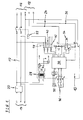
- FIG. 1 shows a schematic diagram of a control device 10 according to a preferred embodiment of the invention.
- the control device 10 is provided for controlling the supply of an electric vehicle during a charging process. Furthermore, the control device 10 together with a charging cable 12 form an assembly, wherein the control device 10 and the charging cable 12 are detachably or permanently connected to each other.
- the control device 10 is coupled to the charging cable 12 or coupled.
- the charging cable 12 connects a mains connection 14 to a power connection 16 of the electric vehicle.
- the mains connection 14 comprises a conductor L1, a neutral conductor N and a protective conductor PE.
- the power supply 14 is provided for a rated voltage of 230V or 115V.
- the power connection 16 of the electric vehicle comprises a switchable conductor L ', a switchable neutral conductor N' and the protective conductor PE.
- the power connection 16 is followed by a charging device of the electric vehicle.
- a fuse system 20 is provided for the conductor L1 and neutral N.
- the security system 20 has at least one fault current switch and / or at least one circuit breaker.
- the fuse system 20 monitors the current through the charging cable 12 for short circuit and / or overload. In the event of a short circuit and / or overload, both the electric vehicle and the control device 10 are disconnected from the mains connection.
- the control device 10 is associated with a circuit breaker 22, through which the switchable conductor L 'and the switchable neutral N' of the power connection 16 on the electric vehicle with the conductor L1 and neutral N of the power supply 14 are coupled.
- the power switch 22 is controllable by the control device 10.
- the control device 10 is further coupled to a control terminal 18 of the electric vehicle.
- the control terminal 18 of the electric vehicle comprises a communication terminal CP and a terminal CS and the protective conductor PE.
- the protective conductor PE belongs to both the power terminal 16 and the control terminal 18.
- the control device 10 also has a corresponding communication port CP and a corresponding port CS on. Accordingly, the control device 10 and the control port 18 of the electric vehicle are coupled to each other via a bidirectional CP line 24 and via a unidirectional CS line 26.
- the communication from the control device 10 to the electric vehicle takes place by means of a pulse width modulated signal via the CP line 24.
- the pulse width modulated signal of the control device 10 is modulated in amplitude by the electric vehicle. For example, in this way, a set in or on the control device 10 maximum charging current can be transmitted from the control device 10 to the electric vehicle.
- the control device 10 has an internal power supply 28, which is the input side coupled to the conductor L1 and the neutral conductor N and the output side provides a DC voltage for the supply of the control and monitoring device 10.
- DC voltages of +12 V and -12 V are provided.
- the control device 10 comprises a microprocessor 30.
- the microprocessor 30 is supplied with DC voltages by the internal power supply 28.
- the control device 10 has a serial interface 32, which is bidirectionally coupled to the microprocessor 30.
- the serial interface 32 is a so-called RS485 interface. This is a standardized interface, via which the control device 10 can be coupled to a computer device.
- the serial interface 32 comprises a first terminal A and a second terminal B.
- a third terminal M is coupled to the ground potential of the control device 10. Via the serial interface 32, the maximum charging current can be set in or on the control device 10.
- the control device 10 has a plurality of light emitting diodes 34, one of which in FIG. 1 is shown.
- the light-emitting diodes 34 are provided in particular for displaying operating states of the control device 10. For example, operating states such as “switched on”, “charging” or “error” are displayed.
- control device 10 comprises a first digital input E1 and a second digital input E2, to each of which a switch 36 is assigned.
- the digital inputs E1 and E2 are set to the ground potential M of the control device 10.
- the digital inputs E1 and E2 are coupled to the microprocessor 30.
- the digital input E2 may be associated with monitoring a locking of a plug-in device of the charging cable 12 with a socket and lock the charging process, for example, when the lock is open.
- control device 10 has on the output side three potential-free switching contacts 38, 40 and 42, which are each controlled by a relay.
- the three relays are coupled to the input side of the microprocessor 30 and are controlled by this.
- the first switching contact 38 is provided for driving the power switch 22.
- the second switching contact 40 is provided for switching a ventilation.
- the third switching contact 42 is associated with a lock for a plug contact.
- the control device 10 is set up such that the available charging current can be adjusted or adjusted within the framework of a load management within the limit predetermined by the set maximum charging current and the cable capacitance, that is to say in the interval from zero to the limit value.
- FIG. 2 is a schematic two-side view of a housing 80 for the control device 10 according to the preferred embodiment of the invention.
- the two-side view includes a front view and a side view of the housing 80.
- the housing 80 has a height of about 90 mm, a width of about 72 mm, and a depth of about 57 mm.
- the housing 80 has four terminal strips 82, 84, 86 and 88 with six terminals each.
- a first terminal strip 82 has, in particular, the connections for the conductor L1, the switchable conductor L ', the neutral conductor N and the switchable neutral conductor N'.
- a second terminal block 84 has the connections for the circuit breaker 22, the ventilation and the locking of the socket.
- a third terminal block 86 comprises the connections for the protective conductor PE, the CP line 24, the CS line 26, and the LEDs 34.
- a fourth terminal block 88 has the connections for the ground potential M, the first digital input E1 and the second digital Input E2 on.
- the fourth terminal block 88 includes the first terminal A, the second terminal B and the ground potential terminal M of the serial interface 32.
Landscapes
- Engineering & Computer Science (AREA)
- Power Engineering (AREA)
- Transportation (AREA)
- Mechanical Engineering (AREA)
- Life Sciences & Earth Sciences (AREA)
- Sustainable Development (AREA)
- Sustainable Energy (AREA)
- Charge And Discharge Circuits For Batteries Or The Like (AREA)
- Electric Propulsion And Braking For Vehicles (AREA)
Abstract
Description
- Die Erfindung betrifft eine Steuervorrichtung für den Ladevorgang eines Elektrofahrzeugs, das mittels eines Ladekabels an einen Netzanschluss gekoppelt oder koppelbar ist, so dass ein Ladestrom von dem Netzanschluss über das Ladekabel zu dem Elektrofahrzeug fließen kann, wobei der Steuervorrichtung wenigstens ein Schalter zum Schalten des Ladekabels zugeordnet ist, die Steuervorrichtung zum Ansteuern des Schalters vorgesehen ist, und die Steuervorrichtung über das Ladekabel mit dem Elektrofahrzeug kommuniziert.
- Das Aufladen der Akkumulatoren von Elektrofahrzeugen erfolgt beispielsweise an einem Netzanschluss. Dabei ist der maximale Ladestrom vorgegeben. Der maximale Ladestrom hängt vom Netzanschluss sowie von der Belastbarkeit des verwendeten Ladekabels ab.
- Für die Steuerung und Überwachung des Ladevorgangs ist eine Steuervorrichtung vorgesehen. Üblicherweise sind die Steuervorrichtungen jeweils an einen bestimmten maximalen Ladestrom angepasst. Für jeden Ladestrom ist somit eine spezielle Steuervorrichtung erforderlich.
- Der Erfindung liegt die Aufgabe zugrunde, eine Steuervorrichtung für den Ladevorgang eines Elektrofahrzeugs bereit zu stellen, die für mehrere maximale Ladeströme verwendbar ist.
- Diese Aufgabe wird durch den Gegenstand gemäß Anspruch 1 gelöst.
- Gemäß der Erfindung ist vorgesehen, dass der maximale Ladestrom in oder an der Steuervorrichtung einstellbar ist.
- Durch den einstellbaren maximalen Ladestrom kann die erfindungsgemäße Steuervorrichtung für Netzanschlüsse unterschiedlicher Belastbarkeit dynamisch eingestellt werden. Die Belastbarkeit des verwendeten Ladekabels wird automatisch bei der Anpassung berücksichtigt.
- Vorzugsweise umfasst die Steuervorrichtung wenigstens eine Schnittstelle zum Einstellen des maximalen Ladestroms. Insbesondere ist die Schnittstelle eine standardisierte Schnittstelle, so dass der maximale Ladestrom mittels einer EDV-Einrichtung einstellbar ist.
- Bei der bevorzugten Ausführungsform der Erfindung ist die Schnittstelle eine serielle Schnittstelle, beispielsweise eine standardisierte RS485-Schnittstelle.
- Insbesondere ist der maximale Ladestrom als ein pulsweitenmoduliertes Signal von der Steuervorrichtung an das Elektrofahrzeug übertragbar. Auf diese Weise wird das Elektrofahrzeug über den maximal verfügbaren Ladestrom informiert.
- Bei einer speziellen Ausführungsform der Erfindung kann der maximale Ladestrom aus einer Tabelle mit vorbestimmten Werten ausgewählt oder auswählbar sein. Zweckmäßigerweise kann eine solche Tabelle die Werte von 6 A, 10 A, 13 A, 16 A, 20 A, 30 A, 32 A, 63 A, 70 und/oder 80 A aufweisen.
- Eine Weiterbildung sieht vor, dass die Steuervorrichtung eine Einrichtung zum Lastmanagement aufweist, die den Ladestrom innerhalb der durch den eingestellten maximalen Ladestrom und die Kapazität des Ladekabels vorgegebenen Grenze anpasst oder einstellt oder regelt. Die Grenze ist hierbei der kleinere der beiden Werte, wenn also die Kabelkapazität einen größeren Ladestrom als den eingestellte maximale Ladestrom ermöglichen würde, so ist die Grenze der eingestellte maximale Ladestrom, wenn aber der eingestellte maximale Ladestrom größer als der gemäß Leitungskapazität maximal möglichen Ladestrom ist, so ist der gemäß Leitungskapazität maximal mögliche Ladestrom die Grenze.
- Vorzugsweise umfasst die Steuervorrichtung wenigstens einen Mikroprozessor. Dies ermöglicht eine besondere kompakte Steuervorrichtung.
- Weiterhin kann die Steuervorrichtung wenigstens einen digitalen Eingang zum Freigeben und/oder Sperren des Ladevorgangs aufweisen.
- Außerdem kann die Steuervorrichtung wenigstens eine Einrichtung zum Anzeigen von einem oder mehreren Betriebszuständen aufweisen.
- Vorteilhafte Ausgestaltungen und Weiterbildungen sind in den abhängigen Ansprüchen angegeben.
- Die Erfindung wird nachstehend auch hinsichtlich weiterer Merkmale und Vorteile anhand der Beschreibung eines Ausführungsbeispiels und unter Bezugnahme auf die beigefügten Zeichnungen näher erläutert. Es zeigen
- FIG 1
- ein schematisches Schaltbild einer Steuervorrichtung gemäß einer bevorzugten Ausführungsform der Erfindung, und
- FIG 2
- eine schematische Zweiseitenansicht eines Gehäuses für die Steuervorrichtung gemäß der bevorzugten Ausführungsform der Erfindung.
-
FIG 1 zeigt ein schematisches Schaltbild einer Steuervorrichtung 10 gemäß einer bevorzugten Ausführungsform der Erfindung. Die Steuervorrichtung 10 ist für die Steuerung der Versorgung eines Elektrofahrzeuges während eines Ladevorgangs vorgesehen. Weiterhin kann die Steuervorrichtung 10 zusammen mit einem Ladekabel 12 eine Baugruppe bilden, wobei die Steuervorrichtung 10 und das Ladekabel 12 lösbar oder dauerhaft miteinander verbunden sind. - In
FIG 1 ist die Steuervorrichtung 10 mit dem Ladekabel 12 gekoppelt oder koppelbar. Das Ladekabel 12 verbindet einen Netzanschluss 14 mit einem Leistungsanschluss 16 des Elektrofahrzeugs. Der Netzanschluss 14 umfasst einen Leiter L1, einen Nullleiter N und einen Schutzleiter PE. In diesem Beispiel ist der Netzanschluss 14 für eine Nennspannung von 230 V oder 115 V vorgesehen. Der Leistungsanschluss 16 des Elektrofahrzeugs umfasst einen schaltbaren Leiter L', einen schaltbaren Nullleiter N' und den Schutzleiter PE. Dem Leistungsanschluss 16 ist eine Ladevorrichtung des Elektrofahrzeugs nachgeschaltet. Für den Leiter L1 und den Nullleiter N ist ein Sicherungssystem 20 vorgesehen. Das Sicherungssystem 20 weist wenigstens einen Fehlerstromschalter und/oder wenigstens einen Leitungsschutzschalter auf. Durch das Sicherungssystem 20 wird der Strom durch das Ladekabel 12 hinsichtlich Kurzschluss und/oder Überlastung überwacht. Bei einem Kurzschluss und/oder einer Überlastung werden sowohl das Elektrofahrzeug als auch die Steuervorrichtung 10 vom Netzanschluss getrennt. - Der Steuervorrichtung 10 ist ein Leistungsschalter 22 zugeordnet, durch den der schaltbare Leiter L' und der schaltbare Nullleiter N' des Leistungsanschlusses 16 am Elektrofahrzeug mit dem Leiter L1 bzw. Nullleiter N des Netzanschlusses 14 koppelbar sind. Der Leistungsschalter 22 ist durch die Steuervorrichtung 10 steuerbar.
- Die Steuervorrichtung 10 ist weiterhin mit einem Steueranschluss 18 des Elektrofahrzeugs gekoppelt. Der Steueranschluss 18 des Elektrofahrzeugs umfasst einen Kommunikationsanschluss CP und einen Anschluss CS sowie den Schutzleiter PE. Somit gehört der Schutzleiter PE sowohl zum Leistungsanschluss 16 als auch zum Steueranschluss 18. Die Steuervorrichtung 10 weist ebenfalls einen korrespondierenden Kommunikationsanschluss CP und einen korrespondierenden Anschluss CS auf. Dementsprechend sind die Steuervorrichtung 10 und der Steueranschluss 18 des Elektrofahrzeugs über eine bidirektionale CP-Leitung 24 und über eine unidirektionale CS-Leitung 26 miteinander gekoppelt.
- Die Kommunikation von der Steuervorrichtung 10 zu dem Elektrofahrzeug erfolgt mittels eines pulsweitenmodulierten Signals über die CP-Leitung 24. Für die Kommunikation von dem Elektrofahrzeug zu der Steuervorrichtung 10 wird das pulsweitenmodulierte Signal der Steuervorrichtung 10 durch das Elektrofahrzeug in der Amplitude moduliert. Beispielsweise kann auf diese Weise ein in oder an der Steuervorrichtung 10 eingestellter maximaler Ladestrom von der Steuervorrichtung 10 an das Elektrofahrzeug übertragen werden.
- Die Steuervorrichtung 10 weist ein internes Netzteil 28 auf, das eingangsseitig mit dem Leiter L1 und dem Nullleiter N gekoppelt ist und ausgangsseitig eine Gleichspannung für die Versorgung der Steuer- und Überwachungsvorrichtung 10 bereitstellt. In diesem Beispiel werden Gleichspannungen von +12 V und -12 V bereitgestellt.
- Insbesondere umfasst die Steuervorrichtung 10 einen Mikroprozessor 30. Der Mikroprozessor 30 wird von dem internen Netzteil 28 mit Gleichspannungen versorgt. Die Steuervorrichtung 10 weist eine serielle Schnittstelle 32 auf, die bidirektional mit dem Mikroprozessor 30 gekoppelt ist. In diesem Beispiel handelt es sich bei der seriellen Schnittstelle 32 um eine sogenannte RS485-Schnittstelle. Dabei handelt es sich um eine standardisierte Schnittstelle, über die die Steuervorrichtung 10 mit einer EDV-Einrichtung koppelbar ist. Die serielle Schnittstelle 32 umfasst einen ersten Anschluss A und einen zweiten Anschluss B. Ein dritter Anschluss M ist mit dem Massepotential der Steuervorrichtung 10 gekoppelt. Über die serielle Schnittstelle 32 kann der maximale Ladestrom in oder an der Steuervorrichtung 10 eingestellt werden.
- Die Steuervorrichtung 10 weist mehrere Leuchtdioden 34 auf, von denen eine in
FIG 1 dargestellt ist. Die Leuchtdioden 34 sind insbesondere zum Anzeigen von Betriebszuständen der Steuervorrichtung 10 vorgesehen. Beispielsweise werden Betriebszustände wie "Eingeschaltet", "Laden" oder "Fehler" angezeigt. - Weiterhin umfasst die Steuervorrichtung 10 einen ersten digitalen Eingang E1 und einen zweiten digitalen Eingang E2, denen jeweils ein Schalter 36 zugeordnet ist. Durch das Schließen des jeweiligen Schalters 36 werden die digitale Eingänge E1 bzw. E2 auf das Massepotential M der Steuervorrichtung 10 gesetzt. Die digitalen Eingänge E1 und E2 sind mit dem Mikroprozessor 30 gekoppelt. Durch das Betätigen des Schalters 36 für den digitalen Eingang E1 wird der Ladevorgang freigegeben. Der digitale Eingang E2 kann einer Überwachung einer Verriegelung einer Steckvorrichtung des Ladekabels 12 mit einer Steckdose zugeordnet sein und beispielsweise bei geöffneter Verriegelung den Ladevorgang sperren.
- Schließlich weist die Steuervorrichtung 10 ausgangsseitig drei potentialfreie Schaltkontakte 38, 40 und 42 auf, die von jeweils einem Relais angesteuert werden. Die drei Relais sind eingangsseitig mit dem Mikroprozessor 30 gekoppelt und werden von diesem angesteuert. Der erste Schaltkontakt 38 ist zum Ansteuern des Leistungsschalters 22 vorgesehen. Der zweite Schaltkontakt 40 ist zum Schalten einer Belüftung vorgesehen. Der dritte Schaltkontakt 42 ist einer Verriegelung für einen Steckkontakt zugeordnet.
- Die Steuervorrichtung 10 ist so eingerichtet, dass der verfügbare Ladestrom im Rahmen eines Lastmanagements innerhalb der durch den eingestellten maximalen Ladestrom und die Kabelkapazität vorgegebenen Grenze, das heißt im Intervall von Null bis zum Grenzwert, angepasst oder eingestellt oder geregelt werden kann.
- In
FIG 2 ist eine schematische Zweiseitenansicht eines Gehäuses 80 für die Steuervorrichtung 10 gemäß der bevorzugten Ausführungsform der Erfindung dargestellt. Die Zweiseitenansicht umfasst eine Vorderansicht und eine Seitenansicht des Gehäuses 80. In diesem Beispiel hat das Gehäuse 80 eine Höhe von etwa 90 mm, eine Breite von etwa 72 mm und eine Tiefe von etwa 57 mm. - Das Gehäuse 80 weist vier Klemmleisten 82, 84, 86 und 88 mit jeweils sechs Anschlüssen auf. Eine erste Klemmleiste 82 weist insbesondere die Anschlüsse für den Leiter L1, den schaltbaren Leiter L', den Nullleiter N und den schaltbaren Nullleiter N' auf. Eine zweite Klemmleiste 84 weist die Anschlüsse für den Leistungsschalter 22, die Belüftung und die Verriegelung der Steckdose auf. Eine dritte Klemmleiste 86 umfasst die Anschlüsse für den Schutzleiter PE, die CP-Leitung 24, die CS-Leitung 26, und die Leuchtdioden 34. Eine vierte Klemmleiste 88 weist die Anschlüsse für das Massepotential M, den ersten digitalen Eingang E1 und den zweiten digitalen Eingang E2 auf. Außerdem umfasst die vierte Klemmleiste 88 den ersten Anschluss A, den zweiten Anschluss B und den Anschluss für das Massepotential M der seriellen Schnittstelle 32.
-
- 10
- Steuervorrichtung
- 12
- Ladekabel
- 14
- Netzanschluss
- 16
- Leistungsanschluss
- 18
- Steueranschluss
- 20
- Sicherungssystem
- 22
- Leistungsschalter
- 24
- CP-Leitung
- 26
- CS-Leitung
- 28
- internes Netzteil
- 30
- Mikroprozessor
- 32
- serielle Schnittstelle
- 34
- Leuchtdiode
- 36
- Schalter
- 38
- erster Schaltkontakt
- 40
- zweiter Schaltkontakt
- 42
- dritter Schaltkontakt
- 80
- Gehäuse
- 82
- erste Klemmleiste
- 84
- zweite Klemmleiste
- 86
- dritte Klemmleiste
- 88
- vierte Klemmleiste
- L1
- Leiter
- N
- Nullleiter
- PE
- Schutzleiter
- L'
- schaltbarer Leiter
- N'
- schaltbarer Nullleiter
- CP
- Kommunikationsanschluss
- CS
- Anschluss
- E1
- erster digitaler Eingang
- E2
- zweiter digitaler Eingang
- M
- Massepotential
- A
- erster Anschluss der seriellen Schnittstelle 32
- B
- zweiter Anschluss der seriellen Schnittstelle 32
Claims (10)
- Steuervorrichtung (10) für den Ladevorgang eines Elektrofahrzeugs, das mittels eines Ladekabels (12) an einen Netzanschluss (14) gekoppelt oder koppelbar ist, so dass ein Ladestroms von dem Netzanschluss (14) über das Ladekabel (12) zu dem Elektrofahrzeug fließen kann, wobei- der Steuervorrichtung (10) wenigstens ein Schalter (22) zum Schalten des Ladekabels (12) zugeordnet ist,- die Steuervorrichtung (10) zum Ansteuern des Schalters (22) vorgesehen ist, und- die Steuervorrichtung (10) über das Ladekabel (12) mit dem Elektrofahrzeug kommuniziert,dadurch gekennzeichnet, dass
der maximale Ladestrom in oder an der Steuervorrichtung (10) einstellbar ist. - Steuervorrichtung nach Anspruch 1,
dadurch gekennzeichnet, dass
die Steuervorrichtung (10) wenigstens eine Schnittstelle (32) zum Einstellen des maximalen Ladestroms aufweist. - Steuervorrichtung nach Anspruch 2,
dadurch gekennzeichnet, dass
die Schnittstelle (32) eine standardisierte Schnittstelle ist, so dass der maximalen Ladestrom mittels einer EDV-Einrichtung einstellbar ist. - Steuervorrichtung nach Anspruch 2 oder 3,
dadurch gekennzeichnet, dass
die Schnittstelle (32) eine serielle Schnittstelle ist. - Steuervorrichtung nach einem der vorhergehenden Ansprüche, dadurch gekennzeichnet, dass
der maximale Ladestrom als ein pulsweitenmoduliertes Signal von der Steuervorrichtung (10) an das Elektrofahrzeug übertragbar ist. - Steuervorrichtung nach einem der vorhergehenden Ansprüche, dadurch gekennzeichnet, dass
der maximale Ladestrom aus einer Tabelle mit vorbestimmten Werten ausgewählt oder auswählbar ist. - Steuervorrichtung nach einem der vorhergehenden Ansprüche, dadurch gekennzeichnet, dass
die Steuervorrichtung (10) eine Einrichtung zum Lastmanagement aufweist, die den Ladestrom innerhalb der durch den eingestellten maximalen Ladestrom und die Kapazität des Ladekabels (12) vorgegebenen Grenze anpasst oder einstellt oder regelt. - Steuervorrichtung nach einem der vorhergehenden Ansprüche, dadurch gekennzeichnet, dass
die Steuervorrichtung (10) wenigstens einen Mikroprozessor (30) aufweist. - Steuervorrichtung nach einem der vorhergehenden Ansprüche, dadurch gekennzeichnet, dass
die Steuervorrichtung (10) wenigstens einen digitalen Eingang (E1, E2) zum Freigeben und/oder Sperren des Ladevorgangs aufweist. - Steuervorrichtung nach einem der vorhergehenden Ansprüche, dadurch gekennzeichnet, dass
die Steuervorrichtung (10) wenigstens eine Einrichtung (34) zum Anzeigen von einem oder mehreren Betriebszuständen aufweist.
Applications Claiming Priority (1)
| Application Number | Priority Date | Filing Date | Title |
|---|---|---|---|
| DE202011000704U DE202011000704U1 (de) | 2011-03-28 | 2011-03-28 | Steuervorrichtung für den Ladevorgang eines Elektrofahrzeugs |
Publications (2)
| Publication Number | Publication Date |
|---|---|
| EP2505420A2 true EP2505420A2 (de) | 2012-10-03 |
| EP2505420A3 EP2505420A3 (de) | 2017-08-02 |
Family
ID=45932192
Family Applications (1)
| Application Number | Title | Priority Date | Filing Date |
|---|---|---|---|
| EP12161225.3A Withdrawn EP2505420A3 (de) | 2011-03-28 | 2012-03-26 | Steuervorrichtung für den Ladevorgang eines Elektrofahrzeugs |
Country Status (2)
| Country | Link |
|---|---|
| EP (1) | EP2505420A3 (de) |
| DE (1) | DE202011000704U1 (de) |
Family Cites Families (4)
| Publication number | Priority date | Publication date | Assignee | Title |
|---|---|---|---|---|
| JP4719776B2 (ja) * | 2008-07-14 | 2011-07-06 | トヨタ自動車株式会社 | 充電ケーブル、充電制御装置、及び車両充電システム |
| JP4810564B2 (ja) * | 2008-11-17 | 2011-11-09 | トヨタ自動車株式会社 | 電動車両用の充電ケーブルおよびその管理方法 |
| DE102009025302B4 (de) * | 2009-06-15 | 2011-07-28 | Rwe Ag, 45128 | Verbindung zwischen Ladestation und Elektrofahrzeug |
| DE102010011162A1 (de) * | 2009-07-15 | 2011-02-03 | Siemens Aktiengesellschaft | Verfahren zur Kommunikation zwischen einem Elektrofahrzeug und einer Ladestelle zum elektrischen Laden zumindest eines Energiespeichers des Elektrofahrzeugs |
-
2011
- 2011-03-28 DE DE202011000704U patent/DE202011000704U1/de not_active Expired - Lifetime
-
2012
- 2012-03-26 EP EP12161225.3A patent/EP2505420A3/de not_active Withdrawn
Non-Patent Citations (1)
| Title |
|---|
| None |
Also Published As
| Publication number | Publication date |
|---|---|
| DE202011000704U1 (de) | 2012-04-03 |
| EP2505420A3 (de) | 2017-08-02 |
Similar Documents
| Publication | Publication Date | Title |
|---|---|---|
| DE112020001101T5 (de) | Verriegelungsvorrichtung für hochspannungsgeräte | |
| DE10248679A1 (de) | Fahrzeugbordnetz mit Batteriezustandserkennung am Pluspol der Batterie | |
| WO2004069600A1 (de) | Zwei-spannungs-bordnetz | |
| DE102014207993A1 (de) | Energieübertragungsvorrichtung und Bordnetz | |
| WO2023020779A1 (de) | Ladevorrichtung und verfahren zum laden mindestens eines elektrofahrzeugs | |
| EP3695475A1 (de) | Sicherungsmodul und feldbussystem mit sicherungsmodul | |
| EP0417480A2 (de) | Verkabelungssystem für Fahrzeuge | |
| EP3752385A1 (de) | Einstellen eines kommunikationsparameters eines kommunikationsmoduls einer ladestation | |
| DE102018126787B4 (de) | Ladestation für Elektrofahrzeuge mit mindestens zwei Ladeanschlüssen und einer wahlweise auf diese schaltbare Leistungselektronikeinheit | |
| DE102015223626B4 (de) | Steuerelektronik für ein land- oder forstwirtschaftliches Fahrzeug | |
| DE102007029979B3 (de) | Verfahren zur Inbetriebnahme eines Mehrkanaldimmers | |
| EP3028385A1 (de) | Anordnung zum anschluss einer komponente an ein master- steuergerät eines kraftfahrzeugs | |
| EP2505420A2 (de) | Steuervorrichtung für den Ladevorgang eines Elektrofahrzeugs | |
| DE102018215769B4 (de) | Fahrzeugbordnetz mit einem Energiespeicher und Ladeanschlüssen | |
| EP0903008A1 (de) | Anordnung mit einem elektronisch kommutierten motor | |
| EP0103151B1 (de) | Verfahren zum Betrieb einer elektrischen Energieverteilungsanlage | |
| DE102024107107A1 (de) | Power-over-cable-filter für serielle kommunikationslinks | |
| DE102019217783A1 (de) | Vorrichtung und Verfahren zum Laden einer Anzahl elektrisch angetriebener Kraftfahrzeuge | |
| DE102015208495A1 (de) | Steuerelektronik für ein land- oder forstwirtschaftliches Fahrzeug | |
| DE102013002080A1 (de) | Elektrische Konvertierungseinrichtung für ein Elektro- oder Hybridfahrzeug | |
| EP1068700B1 (de) | Signalisierungsendstufe zur erzeugung digitaler spannungssignale auf einem bussystem | |
| EP3115297B1 (de) | Elektrisches gerät für ein luftfahrzeug, geräteanordnung für ein luftfahrzeug, verbindungseinheit, fluggastsitz sowie baureihe von elektrischen geräten für luftfahrzeuge | |
| EP1222726A1 (de) | Verfahren zur sicheren ankopplung eines fremdspannungsnetzes an ein betriebsspannungsnetz und schaltungsanordnung zur durchführung des verfahrens | |
| DE102019203515A1 (de) | Verfahren zur Energieversorgung von Verbrauchern eines Bordnetzes für ein Fahrzeug sowie ein Bordnetz für ein Fahrzeug | |
| DE102019203519B4 (de) | Verfahren zur Energieversorgung von Verbrauchern eines Bordnetzes für ein Fahrzeug sowie Bordnetz für ein Fahrzeug |
Legal Events
| Date | Code | Title | Description |
|---|---|---|---|
| PUAI | Public reference made under article 153(3) epc to a published international application that has entered the european phase |
Free format text: ORIGINAL CODE: 0009012 |
|
| AK | Designated contracting states |
Kind code of ref document: A2 Designated state(s): AL AT BE BG CH CY CZ DE DK EE ES FI FR GB GR HR HU IE IS IT LI LT LU LV MC MK MT NL NO PL PT RO RS SE SI SK SM TR |
|
| AX | Request for extension of the european patent |
Extension state: BA ME |
|
| PUAL | Search report despatched |
Free format text: ORIGINAL CODE: 0009013 |
|
| AK | Designated contracting states |
Kind code of ref document: A3 Designated state(s): AL AT BE BG CH CY CZ DE DK EE ES FI FR GB GR HR HU IE IS IT LI LT LU LV MC MK MT NL NO PL PT RO RS SE SI SK SM TR |
|
| AX | Request for extension of the european patent |
Extension state: BA ME |
|
| RIC1 | Information provided on ipc code assigned before grant |
Ipc: B60L 11/18 20060101AFI20170623BHEP Ipc: B60L 3/00 20060101ALI20170623BHEP Ipc: B60L 3/04 20060101ALI20170623BHEP |
|
| RAP1 | Party data changed (applicant data changed or rights of an application transferred) |
Owner name: ABL SURSUM BAYERISCHE ELEKTROZUBEHOER GMBH & CO. K |
|
| 17P | Request for examination filed |
Effective date: 20180131 |
|
| RBV | Designated contracting states (corrected) |
Designated state(s): AL AT BE BG CH CY CZ DE DK EE ES FI FR GB GR HR HU IE IS IT LI LT LU LV MC MK MT NL NO PL PT RO RS SE SI SK SM TR |
|
| 17Q | First examination report despatched |
Effective date: 20180823 |
|
| STAA | Information on the status of an ep patent application or granted ep patent |
Free format text: STATUS: THE APPLICATION HAS BEEN WITHDRAWN |
|
| 18W | Application withdrawn |
Effective date: 20181023 |