EP2505402A1 - Panel structure of sunroof - Google Patents
Panel structure of sunroof Download PDFInfo
- Publication number
- EP2505402A1 EP2505402A1 EP12161593A EP12161593A EP2505402A1 EP 2505402 A1 EP2505402 A1 EP 2505402A1 EP 12161593 A EP12161593 A EP 12161593A EP 12161593 A EP12161593 A EP 12161593A EP 2505402 A1 EP2505402 A1 EP 2505402A1
- Authority
- EP
- European Patent Office
- Prior art keywords
- panel
- outer peripheral
- weather strip
- roof panel
- engaging
- Prior art date
- Legal status (The legal status is an assumption and is not a legal conclusion. Google has not performed a legal analysis and makes no representation as to the accuracy of the status listed.)
- Withdrawn
Links
- 230000002093 peripheral effect Effects 0.000 claims abstract description 106
- 239000000463 material Substances 0.000 claims description 36
- 229920005989 resin Polymers 0.000 claims description 12
- 239000011347 resin Substances 0.000 claims description 12
- 229910000831 Steel Inorganic materials 0.000 claims description 3
- 239000010959 steel Substances 0.000 claims description 3
- 238000004519 manufacturing process Methods 0.000 description 6
- 239000000853 adhesive Substances 0.000 description 5
- XLYOFNOQVPJJNP-UHFFFAOYSA-N water Substances O XLYOFNOQVPJJNP-UHFFFAOYSA-N 0.000 description 4
- 238000000034 method Methods 0.000 description 3
- 125000006850 spacer group Chemical group 0.000 description 3
- 239000011521 glass Substances 0.000 description 2
- 238000000465 moulding Methods 0.000 description 2
- 238000003825 pressing Methods 0.000 description 2
- 230000003014 reinforcing effect Effects 0.000 description 2
- 238000005452 bending Methods 0.000 description 1
- 230000000694 effects Effects 0.000 description 1
- 239000013013 elastic material Substances 0.000 description 1
- 239000002184 metal Substances 0.000 description 1
- 229920005668 polycarbonate resin Polymers 0.000 description 1
- 239000004431 polycarbonate resin Substances 0.000 description 1
- 238000007789 sealing Methods 0.000 description 1
- 239000003566 sealing material Substances 0.000 description 1
- 229920003002 synthetic resin Polymers 0.000 description 1
- 239000000057 synthetic resin Substances 0.000 description 1
- 229920002803 thermoplastic polyurethane Polymers 0.000 description 1
Images

Classifications
-
- B—PERFORMING OPERATIONS; TRANSPORTING
- B60—VEHICLES IN GENERAL
- B60J—WINDOWS, WINDSCREENS, NON-FIXED ROOFS, DOORS, OR SIMILAR DEVICES FOR VEHICLES; REMOVABLE EXTERNAL PROTECTIVE COVERINGS SPECIALLY ADAPTED FOR VEHICLES
- B60J10/00—Sealing arrangements
- B60J10/20—Sealing arrangements characterised by the shape
- B60J10/24—Sealing arrangements characterised by the shape having tubular parts
-
- B—PERFORMING OPERATIONS; TRANSPORTING
- B60—VEHICLES IN GENERAL
- B60J—WINDOWS, WINDSCREENS, NON-FIXED ROOFS, DOORS, OR SIMILAR DEVICES FOR VEHICLES; REMOVABLE EXTERNAL PROTECTIVE COVERINGS SPECIALLY ADAPTED FOR VEHICLES
- B60J10/00—Sealing arrangements
- B60J10/80—Sealing arrangements specially adapted for opening panels, e.g. doors
- B60J10/82—Sealing arrangements specially adapted for opening panels, e.g. doors for movable panels in roofs
Definitions
- This disclosure generally relates to a panel structure of a sunroof.
- Patent reference 1 A known panel structure of a sunroof is disclosed in JP2004-243792A (hereinafter referred to as Patent reference 1).
- the known panel structure of the sunroof disclosed in the Patent reference 1 includes a roof panel made of glass material, a rim made of resin material and mounted on an outer peripheral edge of the roof panel along an entire circumference of the roof panel, and a weather strip made of an elastic material and formed into a frame-like shape, which is attached to an outer peripheral edge of the rim along an entire circumference of the rim.
- an inner panel made from metal plate and formed into a frame-like shape is attached to the outer peripheral edge of the roof panel or to the outer peripheral edge of the rim along the entire circumference thereof.
- the inner panel connects the roof panel to a function bracket related to an opening and closing operation of the roof panel.
- the known panel structure of the sunroof is constituted by four components, that is, the roof panel, the rim, the weather strip and the inner panel. This leads to an increase in the number of the components, resulting in a cost increase.
- Patent reference 2 Another known panel structure is disclosed in JP2003-094953A (hereinafter referred to as Patent reference 2).
- Patent reference 2 the panel structure which is constituted by three components and does not include a rim is suggested.
- a vertical flange is provided at a peripheral edge of an inner panel.
- a weather strip is mounted on the roof panel by inserting the weather strip between the roof panel and the inner panel while having the vertical flange fitted and held in a groove provided at of the weather strip.
- the known panel structure of the sunroof disclosed in the Patent reference 2 does not include the rim, and thus the vertical flange of the inner panel may need to be arranged outwardly relative to an outline (an outer peripheral edge) of the roof panel in order to mount the weather strip on the inner panel. Therefore, the weather strip may need to be configured so that a sufficient length of the weather strip extends from the outer peripheral edge of the roof panel. In this case, consumption of material for forming the weather strip increases. Further, in a case where the increased length of the weather strip extends from the outer peripheral edge of the roof panel, flapping may occur to the entire weather strip at corner portions where the weather strip is bent to form the frame-like shape. Consequently, the corner portions may need to be formed in a manner that the aforementioned flapping does not occur, which may increase a manufacturing workload. As described above, the increase in the consumption of the material of the weather strip and in the manufacturing workload results in a cost increase.
- the panel structure of the sunroof is constituted by three components, that is, the roof panel, the weather strip and the inner panel, and therefore the number of components is reduced.
- the inner panel supports and secures the weather strip in a manner that the engaging protruding portion is sandwiched and held between the second outer peripheral portion of the inner panel and the first outer peripheral portion of the roof panel, and that the engaging protruding portion is engaged with the engaging recessed portion. Consequently, a position of an outer peripheral edge of the inner panel is less restricted by a position of an outer peripheral edge of the roof panel. Therefore, a length of a portion of the weather strip, the portion which extends from the outer peripheral edge of the roof panel toward the edge portion of the opening, is reduced. This reduces consumption of material for forming the weather strip. Further, shape and configuration of the weather strip may be simplified as a whole, thereby reducing manufacturing workload.
- the length of the weather strip extending from the outer peripheral edge of the roof panel is reduced without increasing the number of the components.
- the panel structure of the sunroof further includes an inclined portion provided at the engaging recessed portion of the inner panel and causing a component force to be generated.
- the component force moves the weather strip in a direction in which the engaging protruding portion is engaged with the engaging recessed portion in a case where the engaging protruding portion is pressed downwardly via the roof panel.
- the aforementioned component force which is generated when the roof panel is fixedly attached onto the inner panel, allows the engagement between the engaging protruding portion and the engaging recessed portion to be completed.
- the panel structure of the sunroof further includes a holding portion provided at the weather strip and holding the second outer peripheral portion of the inner panel between the holding portion and the engaging protruding portion.
- the panel structure of the sunroof further includes a cover portion provided at the weather strip and covering an upper surface of the first outer peripheral portion of the roof panel, wherein the seal portion of the weather strip and a design surface of the cover portion which is connected to the seal portion are made of foamed material, and the engaging protruding portion of the weather strip and a back surface of the cover portion which is connected to the engaging protruding portion are made of resin material which is harder than the foamed material.
- the design surface of the cover portion and the seal portion are made of the foamed material, and thus an integrated appearance between the design surface of the cover portion and the seal portion is enhanced, and an aesthetic quality improves.
- the back surface of the cover portion and the engaging protruding portion are made of the resin material which is harder than the foamed material, rigidity of the cover portion increases compared to a case where, for example, the cover portion is entirely made of the foamed material.
- the panel structure of the sunroof further includes a lip portion provided at the weather strip and standing from an upper surface of the engaging protruding portion.
- the lip portion is configured to be elastically in contact with a bottom surface of the roof panel along the first outer peripheral portion of the roof panel.
- the weather strip at the lip portion, is elastically in contact with the bottom surface of the roof panel along the first outer peripheral portion of the roof panel, water which enters an outer peripheral edge of the upper surface of the engaging protruding portion is restricted from entering onto the inner panel (the engaging recessed portion) from an inner peripheral edge of the upper surface of the engaging protruding portion.
- corrosion-preventive performance of the inner panel improves.
- the panel structure of the sunroof further includes a recessed portion provided at the weather strip and allowing the lip portion to be folded down.
- the panel structure is manufactured to be thinner.
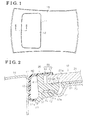
- Fig. 1 is a plan view illustrating a panel structure of a sunroof according to an embodiment disclosed here;
- Fig. 3 is a cross-sectional view illustrating a weather strip according to the embodiment.
- a vehicle roof 10 of, for example, an automobile is provided with an opening 11 formed into a substantially rectangular shape.
- the vehicle roof 10 is also provided with a panel 12 for the vehicle (hereinafter referred to also as the panel 12) formed into a substantially rectangular shape and is configured to open and close the opening 11.
- the inner panel 23 also includes a second outer peripheral portion 32 connected to the engaging recessed portion 31 and positioned below the first outer peripheral portion 21 a of the roof panel 21 while being apart from the roof panel 21.
- the second outer peripheral portion 32 is directed toward the edge portion 11 a of the opening 11.
- the engaging recessed portion 31 is curved in a direction in which a gap, that is, a distance between the engaging recessed portion 31 and the roof panel 21 increases.
- a portion at which the engaging recessed portion 31 is connected to the second outer peripheral portion 32 defines an inclined portion 31 a that gradually rises upwardly toward an outer side of the inner panel 23.
- the adhesive agent 22 is generally applied to be positioned closer to a base end of the inner panel 23, that is, closer to a center of the vehicle.
- the panel 12 includes a weather strip 24 formed into a substantially rectangular ring shape and mounted on the first outer peripheral portion 21 a of the roof panel 21.
- the weather strip 24 includes a body portion 41 formed into a belt shape and surrounding the first outer peripheral portion 21 a of the roof panel 21, and an engaging protruding portion 42 extending from the body portion 41 along the bottom surface of the first outer peripheral portion 21a toward the first outer peripheral portion 21a.
- the engaging protruding portion 42 includes a cross section formed into a substantially hooked shape.
- the engaging protruding portion 42 extends along an entire circumference of the body portion 41 (the first outer peripheral portion 21 a), and includes an engaging portion 42a curved and extending in the downward direction and facing the engaging recessed portion 31.
- the engaging portion 42a is in contact with the inclined portion 31 a of the engaging recessed portion 31 so that the weather strip 24 is restricted from moving toward an outer peripheral direction thereof.
- the weather strip 24 is supported by and secured to the inner panel 23 and to other components by utilizing a room, which is provided between the roof panel 21 and the inner panel 23, and which extends inwardly, in a manner that the engaging protruding portion 42 is sandwiched and held between the roof panel 21 and the inner panel 23.
- the weather strip 24 includes a holding portion 43 formed below the engaging protruding portion 42 into a flange shape and extending from the body portion 41 toward the second outer peripheral portion 32 along the bottom surface of the second outer peripheral portion 32 of the inner panel 23 while being apart from the engaging protruding portion 42.
- the holding portion 43 extends along the entire circumference of the body portion 41, and sandwiches and holds the second outer peripheral portion 32 between the holding portion 43 and the engaging protruding portion 42.
- the weather strip 24 is supported by and secured to the second outer peripheral portion 32 (the inner panel 23) in a manner that the second outer peripheral portion 32 of the inner panel 23 is sandwiched and held between the engaging protruding portion 42 and the holding portion 43 along the entire circumference of the weather strip 24.
- the weather strip 24 includes a back surface-side cover portion 44 formed into a flange shape and extending from an upper edge portion of the body portion 41 toward the first outer peripheral portion 21 a along an upper surface of the first outer peripheral portion 21 a.
- the weather strip 24 is supported by and secured to the first outer peripheral portion 21 a (the roof panel 21) in a manner that the first outer peripheral portion 21 a is sandwiched and held between the engaging protruding portion 42 and the back surface-side cover portion 44 along the entire circumference of the weather strip 24.
- the weather strip 24 includes a lip portion 45 formed along an entire circumference of the engaging protruding portion 42 so as to stand from an upper surface of the engaging protruding portion 42.
- the lip portion 45 in a state where the roof panel 21 is not mounted on the weather strip 24, the lip portion 45 is inclined toward a vehicle outer side, that is, the outer side of the vehicle on which the panel structure of the sunroof is mounted, and in a state where, for example, the roof panel 21 is mounted on the weather strip 24 as illustrated in Fig. 2 , the lip portion 45 is folded down, that is, pushed down toward the vehicle outer side so as to be in contact with the roof panel 21.
- a recessed portion 49 which allows the lip portion 45 to be folded down is formed on the upper surface of the engaging protruding portion 42, to be positioned closer to the vehicle outer side relative to the lip portion 45. As illustrated in Fig.
- the lip portion 45 in a state where the lip portion 45 is pressed by the bottom surface of the roof panel 21, which is, for example, mounted on the engaging protruding portion 42, the lip portion 45 is folded down and is elastically in contact with the bottom surface of the roof panel 21.
- the body portion 41, the engaging protruding portion 42, the holding portion 43, the surface-side cover portion 44, the lip portion 45 and the sub lip 50 are made of resin material M1, which is a hard resin material.
- the weather strip 24 includes a portion 46, which is formed to have a cross section of a substantially arc shape, connected to the upper edge portion and to a lower edge portion of the body portion 41, and protrude toward the edge portion 11a of the opening 11.
- the seal portion 46 extends along the entire circumference of the body portion 41 and is elastically in contact with the edge portion 11 a which the seal portion 46 faces.
- the weather strip 24 includes a design surface-side cover portion 47 formed into a flange shape and extending toward the first outer peripheral portion 21 a of the roof panel 21 along an upper surface of the body portion 41 and along an upper surface of the back surface-side cover portion 44.
- the design surface-side cover portion 47 and the seal portion 46 are made of foamed material M2, which is softer than the resin material M1.
- the design surface-side cover portion 47 may present an enhanced integrated appearance with the seal portion 46, which improves an aesthetic quality.
- the design surface-side cover portion 47 and the back surface-side cover portion 44 constitute a cover portion 48.
- the weather strip 24 is made of the resin material M1 and the foamed material M2 by a double-molding process.
- the cover portion 48 is constituted by the back surface-side cover portion 44 and the design surface-side cover portion 47, which are made of different materials from each other and joined to each other to form a layer in order to favorably assure rigidity of the cover portion 48 without sacrificing a design performance thereof.
- the weather strip 24 is mounted on the inner panel 23 from an outside (that is, an outer peripheral side) of the second outer peripheral portion 32 so that the second outer peripheral portion 32 is sandwiched and held between the engaging protruding portion 42 and the holding portion 43 as illustrated in Fig. 3 .
- a position of the weather strip 24 (the engaging protruding portion 42) is set relative to the second outer peripheral portion 32 in a manner that the engaging portion 42a, which enters and reaches the engaging recessed portion 31, is engaged with the inclined portion 31a of the engaging recessed portion 31.
- the weather strip 24 is placed on and temporarily mounted on the second outer peripheral portion 32 of the inner panel 23.
- the adhesive agent 22 is applied on an upper surface of part of the inner panel 23, the part which is closer to an inner peripheral portion relative to the engaging recessed portion 31, and the roof panel 21 is mounted from above the inner panel 23.
- the engaging protruding portion 42 on which the roof panel 21 is placed, serves as a spacer interposed between the inner panel 23 and the roof panel 21 fixedly attached to the inner panel 23 via the adhesive agent 22.
- the engaging protruding portion 42 is pressed downwardly by the roof panel 21, and thus a component force that moves the weather strip 24 in a direction in which the engaging protruding portion 42 engages with the second outer peripheral portion 32 (that is, toward an inner peripheral side) is generated at the inclined portion 31a with which the engaging portion 42a is in contact.
- the weather strip 24 is temporarily mounted on the second outer peripheral portion 32 and where the engaging protruding portion 42 is not completely engaged with the engaging recessed portion 31, the aforementioned component force that is generated when the roof panel 21 is fixedly attached onto the inner panel 23 allows the engaging portion 42a to slide along the inclined portion 31 a, and thus the engagement between the engaging protruding portion 42 and the engaging recessed portion 31 is completed. Consequently, the second outer peripheral portion 32 is appropriately sandwiched and held between the engaging protruding portion 42 and the holding portion 43.
- the cover portion 48 is pressed by the first outer peripheral portion 21a of the roof panel 21, and therefore bends about a base end of the cover portion 48 (that is, the portion at which the cover portion 48 is connected to the body portion 41) toward the body portion 41. In other words, the cover portion 48 is deformed so as to be received between the body portion 41 and the roof panel 21.
- the roof panel 21 is evenly biased by the cover portion 48 at the first outer peripheral portion 21a toward a center of the roof panel 21 so as to be correctly positioned relative to the inner panel 23 and to other components.
- the roof panel 21 is fixedly mounted on the inner panel 23.
- the lip portion 45 which is pressed by the bottom surface of the roof panel 21 (the first outer peripheral portion 21 a) that is mounted on the engaging protruding portion 42, comes to be folded down and elastically comes to contact with the bottom surface of the roof panel 21.
- the seal portion 46 of the weather strip 24 is elastically in contact with the edge portion 11a of the opening 11, and thus water-tightness against ingress of water toward a vehicle interior side is ensured.
- the cover portion 48 is elastically in contact with the upper surface of the first outer peripheral portion 21a of the roof panel 21 and the lip portion 45 is elastically in contact with the bottom surface of the first outer peripheral portion 21a, and thus water-tightness against ingress of water toward the engaging recessed portion 31 is ensured.
- the panel structure of the sunroof is constituted by three components, that is, the roof panel 21, the weather strip 24 and the inner panel 23, and therefore the number of the components is reduced, and eventually, costs are reduced.
- the inner panel 23 supports and secures the weather strip 24 in a manner that the engaging protruding portion 42 is sandwiched and held between the second outer peripheral portion 32 of the inner panel 23 and the first outer peripheral portion 21a of the roof panel 21, and that the engaging protruding portion 42 is engaged with the second outer peripheral portion 32 of the inner panel 23.
- a position of an outer peripheral edge of the inner panel 23 is less restricted by a position of an outer peripheral edge (an end portion) of the roof panel 21. Therefore, a length of a portion of the weather strip 24, the portion which extends from the outer peripheral edge of the roof panel 21 toward the edge portion 11a of the opening 11, is reduced. This reduces the consumption of the material for forming the weather strip 24.
- corner portions of the weather strip 24 do not need to be formed in a similar manner to that of a known weather strip, that is, in a manner that flapping does not occur at the corner portions of the weather strip, This may simplify the shape and configuration of the weather strip 24 as a whole, thereby reducing the consumption of the material and manufacturing workload of the weather strip 24. As described above, the costs are reduced as a result of the reduction in the consumption of the material and in the manufacturing workload.
- a design surface of the cover portion 48 (the design surface-side cover portion 47) and the seal portion 46 are made of the foamed material M2, and thus the integrated appearance between the design surface of the cover portion 48 and the seal portion 46 is enhanced and the aesthetic quality improves.
- a back surface of the cover portion 48 (the back surface-side cover portion 44) and, for example, the engaging protruding portion 42 are made of the resin material M1 which is harder than the foamed material M2, the rigidity of the cover portion 48 increases compared to a case where, for example, the cover portion 48 is entirely made of the foamed material M2.
- the weather strip 24, at the lip portion 45 is elastically in contact with the bottom surface of the roof panel 21 along the first outer peripheral portion 21a of the roof panel 21, water which enters an outer peripheral edge of the upper surface of the engaging protruding portion 42 is restricted from entering onto the inner panel 23 (the engaging recessed portion 31) from an inner peripheral edge of the upper surface of the engaging protruding portion 42.
- corrosion-preventive performance of the inner panel 23 improves.
- the cover portion 48 is caused to be folded and bent about the base portion of the cover portion 48 toward the body portion 41.
- the first outer peripheral portion 21a of the roof panel 21 is evenly biased by the cover portion 48 so that the roof panel 21 is correctly positioned relative to the inner panel 23 and to other components.
- the seal portion 46 is formed to have the cross section of the substantially arc shape in a state where the seal portion 46 elastically recovers to an original shape (that is, in a free state).
- the seal portion 46 of the weather strip 24 which is to be mounted on the first outer peripheral portion 21a of the roof panel 21, comes in contact with the edge portion 11a of the opening 11 while remaining in the substantially arc shape, and then comes to be pressed by the edge portion 11a and starts elastically deforming. Consequently, a sealing performance between the weather strip 24 and the edge portion 11a is stabilized along the entire circumference of the weather strip 24.
- the manufacture of the inner panel 23 is more simplified compared to an inner panel including, for example, a vertical wall portion, and at the same time, a part accuracy is assured.
- the engaging protruding portion 42 serves as the spacer interposed between the inner panel 23 and the roof panel 21 fixedly attached to the inner panel 23 via the adhesive agent 22, a gap between the roof panel 21 and the inner panel 23 is easily controlled. Further, there is no need to additionally provide a spacer, which reduces the costs.
- the aforementioned embodiment may be changed or modified as follows.
- the weather strip 24 of the embodiment does not need to include the holding portion 43.
- the roof panel 21 of the embodiment may be made of synthetic resin (four example, semi-permeable polycarbonate resin),
- the foamed material M2 of the embodiment may be replaced with soft resin material which is softer than the resin material M1.
- the edge portion 11a of the opening 11 is formed at the roof panel member, which is a design member of the vehicle roof 10, however, the edge portion 11a may be formed at a reinforcing member reinforcing the roof panel member.
Landscapes
- Engineering & Computer Science (AREA)
- Mechanical Engineering (AREA)
- Seal Device For Vehicle (AREA)
Abstract
A panel structure of a sunroof, includes a roof panel (21) for opening and closing an opening (11) of a vehicle roof (10), an inner panel (23) fixedly attached to a bottom surface of a rrof panel along a first outer peripheral portion (21a) of the roof panel, an engaging recessed portion (31) provided at the inner panel and curved in a downward direction along the first peripheral portion, a second outer peripheral portion (32) provided at the inner panel and positioned the roof while being apart from the roof panel and being directed toward an edge portion (11a) of the opening, a weather strip (24) mounted on the first outer peripheral portion, an engaging protruding portion (42) provided at the weather strip, and a seal portion (46) provided at the weather strip and being elastically contactable with the edge portion.
Description
- This disclosure generally relates to a panel structure of a sunroof.
- A known panel structure of a sunroof is disclosed in
JP2004-243792A Patent reference 1 includes a roof panel made of glass material, a rim made of resin material and mounted on an outer peripheral edge of the roof panel along an entire circumference of the roof panel, and a weather strip made of an elastic material and formed into a frame-like shape, which is attached to an outer peripheral edge of the rim along an entire circumference of the rim. In addition, in this case, it is assumed that an inner panel made from metal plate and formed into a frame-like shape is attached to the outer peripheral edge of the roof panel or to the outer peripheral edge of the rim along the entire circumference thereof. The inner panel connects the roof panel to a function bracket related to an opening and closing operation of the roof panel. In other words, the known panel structure of the sunroof is constituted by four components, that is, the roof panel, the rim, the weather strip and the inner panel. This leads to an increase in the number of the components, resulting in a cost increase. - Another known panel structure is disclosed in
JP2003-094953A - The known panel structure of the sunroof disclosed in the Patent reference 2 does not include the rim, and thus the vertical flange of the inner panel may need to be arranged outwardly relative to an outline (an outer peripheral edge) of the roof panel in order to mount the weather strip on the inner panel. Therefore, the weather strip may need to be configured so that a sufficient length of the weather strip extends from the outer peripheral edge of the roof panel. In this case, consumption of material for forming the weather strip increases. Further, in a case where the increased length of the weather strip extends from the outer peripheral edge of the roof panel, flapping may occur to the entire weather strip at corner portions where the weather strip is bent to form the frame-like shape. Consequently, the corner portions may need to be formed in a manner that the aforementioned flapping does not occur, which may increase a manufacturing workload. As described above, the increase in the consumption of the material of the weather strip and in the manufacturing workload results in a cost increase.
- A need thus exists for a panel structure of a sunroof, where a length of a weather strip extending from an outer peripheral end of a roof panel is reduced without increasing the number of components.
- According to an aspect of this disclosure, a panel structure of a sunroof includes a roof panel for opening and closing an opening of a vehicle roof, an inner panel made from steel plate and fixedly attached to a bottom surface of the roof panel along a first outer peripheral portion of the roof panel, an engaging recessed portion provided at the inner panel and is curved in a downward direction along the first outer peripheral portion of the roof panel, a second outer peripheral portion provided at the inner panel and connected to the engaging recessed portion, the second outer peripheral portion is positioned below the roof panel while being apart from the roof panel and being directed toward an edge portion of the opening, a weather strip mounted on the first outer peripheral portion of the roof panel, an engaging protruding portion provided at the weather strip, the engaging protruding portion is sandwiched and held by the first outer peripheral portion of the roof panel and by the second outer peripheral portion of the inner panel along the first outer peripheral portion of the roof panel, and is engaged with the engaging recessed portion, and a seal portion provided at the weather strip and being elastically contactable with the edge portion of the opening.
- According to the above-described structure, the panel structure of the sunroof is constituted by three components, that is, the roof panel, the weather strip and the inner panel, and therefore the number of components is reduced. Further, the inner panel supports and secures the weather strip in a manner that the engaging protruding portion is sandwiched and held between the second outer peripheral portion of the inner panel and the first outer peripheral portion of the roof panel, and that the engaging protruding portion is engaged with the engaging recessed portion. Consequently, a position of an outer peripheral edge of the inner panel is less restricted by a position of an outer peripheral edge of the roof panel. Therefore, a length of a portion of the weather strip, the portion which extends from the outer peripheral edge of the roof panel toward the edge portion of the opening, is reduced. This reduces consumption of material for forming the weather strip. Further, shape and configuration of the weather strip may be simplified as a whole, thereby reducing manufacturing workload.
- According to the above-described structure, the length of the weather strip extending from the outer peripheral edge of the roof panel is reduced without increasing the number of the components.
- According to another aspect of this disclosure, the panel structure of the sunroof further includes an inclined portion provided at the engaging recessed portion of the inner panel and causing a component force to be generated. The component force moves the weather strip in a direction in which the engaging protruding portion is engaged with the engaging recessed portion in a case where the engaging protruding portion is pressed downwardly via the roof panel.
- According to the above-described structure, in a case where the roof panel is fixedly attached onto the inner panel in a state where the weather strip (the engaging protruding portion) is placed on and is temporarily mounted on the second outer peripheral portion of the inner panel, the engaging protruding portion is pressed downwardly via the roof panel. As a result, the component force for moving the weather strip in the direction in which the engaging protruding portion is engaged with the engaging recessed portion is generated at the engaging recessed portion. Thus, even in a case where the weather strip is temporarily mounted and where the engaging protruding portion is not completely engaged with the engaging recessed portion, the aforementioned component force, which is generated when the roof panel is fixedly attached onto the inner panel, allows the engagement between the engaging protruding portion and the engaging recessed portion to be completed.
- According to a further aspect of this disclosure, the panel structure of the sunroof further includes a holding portion provided at the weather strip and holding the second outer peripheral portion of the inner panel between the holding portion and the engaging protruding portion.
- According to the above-described structure, because the second outer peripheral portion of the inner panel is sandwiched and held between the engaging protruding portion and the holding portion, the weather strip is temporarily mounted on the inner panel in a simple way during assembly of the panel structure. Further, also after the assembly of the panel structure is completed, it is restricted that the weather strip detaches from, for example, the inner panel.
- According to a further aspect of this disclosure, the panel structure of the sunroof further includes a cover portion provided at the weather strip and covering an upper surface of the first outer peripheral portion of the roof panel, wherein the seal portion of the weather strip and a design surface of the cover portion which is connected to the seal portion are made of foamed material, and the engaging protruding portion of the weather strip and a back surface of the cover portion which is connected to the engaging protruding portion are made of resin material which is harder than the foamed material.
- According to the above-described structure, the design surface of the cover portion and the seal portion are made of the foamed material, and thus an integrated appearance between the design surface of the cover portion and the seal portion is enhanced, and an aesthetic quality improves. On the other hand, because the back surface of the cover portion and the engaging protruding portion are made of the resin material which is harder than the foamed material, rigidity of the cover portion increases compared to a case where, for example, the cover portion is entirely made of the foamed material. Thus, even in a case where the roof panel is fixedly attached onto the inner panel in a state where the weather strip (the engaging protruding portion) is placed on and temporarily mounted on the second outer peripheral portion of the inner panel, even if the cover portion that is pressed by the first outer peripheral portion of the roof panel is caused to bend by a pressing force, the cover portion is pulled back smoothly so that the cover portion covers the upper surface of the first outer peripheral portion of the roof panel because the rigidity of the cover portion is appropriately maintained.
- According to a further aspect of this disclosure, the panel structure of the sunroof further includes a lip portion provided at the weather strip and standing from an upper surface of the engaging protruding portion. The lip portion is configured to be elastically in contact with a bottom surface of the roof panel along the first outer peripheral portion of the roof panel.
- According to the above-described structure, because the weather strip, at the lip portion, is elastically in contact with the bottom surface of the roof panel along the first outer peripheral portion of the roof panel, water which enters an outer peripheral edge of the upper surface of the engaging protruding portion is restricted from entering onto the inner panel (the engaging recessed portion) from an inner peripheral edge of the upper surface of the engaging protruding portion. As a result, corrosion-preventive performance of the inner panel improves.
- According to a further aspect of this disclosure, the panel structure of the sunroof further includes a recessed portion provided at the weather strip and allowing the lip portion to be folded down.
- According to the above-described structure, because the recessed portion allows the lip portion to be folded down, the panel structure is manufactured to be thinner.
- According to a further aspect of this disclosure, the lip portion is folded down toward a vehicle outer side.
- According to the above-described structure, the water-tightness improves compared to a case where the lip portion is folded down toward a vehicle inner side.
- The foregoing and additional features and characteristics of this disclosure will become more apparent from the following detailed description considered with the reference to the accompanying drawings, wherein:
-
Fig. 1 is a plan view illustrating a panel structure of a sunroof according to an embodiment disclosed here; -
Fig. 2 is a cross-sectional view taken along line II-II inFig. 1 ; and -
Fig. 3 is a cross-sectional view illustrating a weather strip according to the embodiment. - A panel structure of a sunroof according to an embodiment will be explained with reference to
Figs. 1 to 3 . As shown inFig. 1 , avehicle roof 10 of, for example, an automobile is provided with anopening 11 formed into a substantially rectangular shape. Thevehicle roof 10 is also provided with apanel 12 for the vehicle (hereinafter referred to also as the panel 12) formed into a substantially rectangular shape and is configured to open and close theopening 11. - As shown in
Fig. 2 , theopening 11 includes anedge portion 11 a formed by bending an inner side of the opening 11 (that is, an edge of thevehicle roof 10 defining the opening 11) in a downward direction. Thus, theedge portion 11 a of theopening 11 presents a substantially rectangular tubular shape as a whole. On the other hand, thepanel 12 is provided with aroof panel 21 made of, for example, glass and formed into a substantially rectangular shaped plate so as to match a configuration of theedge portion 11 a. Theroof panel 21 opens and closes theopening 11. Thepanel 12 is also provided with aninner panel 23 made from steel plate into a substantially rectangular frame-like shape. Theinner panel 23 is fixedly attached to a bottom surface of theroof panel 21 with, for example, anadhesive agent 22 made of urethane resin, along a first outerperipheral portion 21a of theroof panel 21. Theinner panel 23 connects the roof panel 21 (thepanel 12 for the vehicle) to a function bracket that is configured to open and close the roof panel 21 (thepanel 12 for the vehicle). Theinner panel 23 includes an engaging recessedportion 31 defined by curving theinner panel 23 in the downward direction and positioned below the first outerperipheral portion 21a of theroof panel 21 along an entire circumference of the first outerperipheral portion 21 a. Theinner panel 23 also includes a second outerperipheral portion 32 connected to the engaging recessedportion 31 and positioned below the first outerperipheral portion 21 a of theroof panel 21 while being apart from theroof panel 21. The second outerperipheral portion 32 is directed toward theedge portion 11 a of theopening 11. Thus, the engaging recessedportion 31 is curved in a direction in which a gap, that is, a distance between the engaging recessedportion 31 and theroof panel 21 increases. A portion at which the engaging recessedportion 31 is connected to the second outerperipheral portion 32 defines aninclined portion 31 a that gradually rises upwardly toward an outer side of theinner panel 23. Theadhesive agent 22 is generally applied to be positioned closer to a base end of theinner panel 23, that is, closer to a center of the vehicle. - Further, the
panel 12 includes aweather strip 24 formed into a substantially rectangular ring shape and mounted on the first outerperipheral portion 21 a of theroof panel 21. Theweather strip 24 includes abody portion 41 formed into a belt shape and surrounding the first outerperipheral portion 21 a of theroof panel 21, and an engaging protrudingportion 42 extending from thebody portion 41 along the bottom surface of the first outerperipheral portion 21a toward the first outerperipheral portion 21a. The engaging protrudingportion 42 includes a cross section formed into a substantially hooked shape. The engaging protrudingportion 42 extends along an entire circumference of the body portion 41 (the first outerperipheral portion 21 a), and includes an engagingportion 42a curved and extending in the downward direction and facing the engaging recessedportion 31. The engagingportion 42a is in contact with theinclined portion 31 a of the engaging recessedportion 31 so that theweather strip 24 is restricted from moving toward an outer peripheral direction thereof. In other words, theweather strip 24 is supported by and secured to theinner panel 23 and to other components by utilizing a room, which is provided between theroof panel 21 and theinner panel 23, and which extends inwardly, in a manner that the engaging protrudingportion 42 is sandwiched and held between theroof panel 21 and theinner panel 23. - Further, the
weather strip 24 includes a holdingportion 43 formed below the engaging protrudingportion 42 into a flange shape and extending from thebody portion 41 toward the second outerperipheral portion 32 along the bottom surface of the second outerperipheral portion 32 of theinner panel 23 while being apart from the engaging protrudingportion 42. The holdingportion 43 extends along the entire circumference of thebody portion 41, and sandwiches and holds the second outerperipheral portion 32 between the holdingportion 43 and the engaging protrudingportion 42. In other words, theweather strip 24 is supported by and secured to the second outer peripheral portion 32 (the inner panel 23) in a manner that the second outerperipheral portion 32 of theinner panel 23 is sandwiched and held between the engaging protrudingportion 42 and the holdingportion 43 along the entire circumference of theweather strip 24. - Further, the
weather strip 24 includes a back surface-side cover portion 44 formed into a flange shape and extending from an upper edge portion of thebody portion 41 toward the first outerperipheral portion 21 a along an upper surface of the first outerperipheral portion 21 a. Thus, theweather strip 24 is supported by and secured to the first outerperipheral portion 21 a (the roof panel 21) in a manner that the first outerperipheral portion 21 a is sandwiched and held between the engaging protrudingportion 42 and the back surface-side cover portion 44 along the entire circumference of theweather strip 24. As illustrated inFig. 3 , theweather strip 24 includes alip portion 45 formed along an entire circumference of the engaging protrudingportion 42 so as to stand from an upper surface of the engaging protrudingportion 42. As illustrated inFig. 3 , in a state where theroof panel 21 is not mounted on theweather strip 24, thelip portion 45 is inclined toward a vehicle outer side, that is, the outer side of the vehicle on which the panel structure of the sunroof is mounted, and in a state where, for example, theroof panel 21 is mounted on theweather strip 24 as illustrated inFig. 2 , thelip portion 45 is folded down, that is, pushed down toward the vehicle outer side so as to be in contact with theroof panel 21. A recessedportion 49 which allows thelip portion 45 to be folded down is formed on the upper surface of the engaging protrudingportion 42, to be positioned closer to the vehicle outer side relative to thelip portion 45. As illustrated inFig. 2 , in a state where thelip portion 45 is pressed by the bottom surface of theroof panel 21, which is, for example, mounted on the engaging protrudingportion 42, thelip portion 45 is folded down and is elastically in contact with the bottom surface of theroof panel 21. - At the upper surface of the engaging protruding
portion 42, asub lip 50 is formed at a vehicle inner side relative to thelip portion 45 so as to protrude in an upward direction. As illustrated inFig. 2 , thesub lip 50 is pressed by the bottom surface of theroof panel 21, which is, for example, mounted on the engaging protrudingportion 42, and is elastically in contact with the bottom surface of theroof panel 21. - The
body portion 41, the engaging protrudingportion 42, the holdingportion 43, the surface-side cover portion 44, thelip portion 45 and thesub lip 50 are made of resin material M1, which is a hard resin material. On the other hand, theweather strip 24 includes aportion 46, which is formed to have a cross section of a substantially arc shape, connected to the upper edge portion and to a lower edge portion of thebody portion 41, and protrude toward theedge portion 11a of theopening 11. Theseal portion 46 extends along the entire circumference of thebody portion 41 and is elastically in contact with theedge portion 11 a which theseal portion 46 faces. Further, theweather strip 24 includes a design surface-side cover portion 47 formed into a flange shape and extending toward the first outerperipheral portion 21 a of theroof panel 21 along an upper surface of thebody portion 41 and along an upper surface of the back surface-side cover portion 44. The design surface-side cover portion 47 and theseal portion 46 are made of foamed material M2, which is softer than the resin material M1. By using the identical material (the foamed material M2) for forming the design surface-side cover portion 47 and theseal portion 46, the design surface-side cover portion 47 may present an enhanced integrated appearance with theseal portion 46, which improves an aesthetic quality. The design surface-side cover portion 47 and the back surface-side cover portion 44 constitute acover portion 48. - In other words, the
weather strip 24 is made of the resin material M1 and the foamed material M2 by a double-molding process. Specifically, thecover portion 48 is constituted by the back surface-side cover portion 44 and the design surface-side cover portion 47, which are made of different materials from each other and joined to each other to form a layer in order to favorably assure rigidity of thecover portion 48 without sacrificing a design performance thereof. - Here, an assembly method of the
panel 12 will be explained. First, theweather strip 24 is mounted on theinner panel 23 from an outside (that is, an outer peripheral side) of the second outerperipheral portion 32 so that the second outerperipheral portion 32 is sandwiched and held between the engaging protrudingportion 42 and the holdingportion 43 as illustrated inFig. 3 . Thus, a position of the weather strip 24 (the engaging protruding portion 42) is set relative to the second outerperipheral portion 32 in a manner that the engagingportion 42a, which enters and reaches the engaging recessedportion 31, is engaged with theinclined portion 31a of the engaging recessedportion 31. In the aforementioned way, theweather strip 24 is placed on and temporarily mounted on the second outerperipheral portion 32 of theinner panel 23. - Next, the
adhesive agent 22 is applied on an upper surface of part of theinner panel 23, the part which is closer to an inner peripheral portion relative to the engaging recessedportion 31, and theroof panel 21 is mounted from above theinner panel 23. At this time, the engaging protrudingportion 42, on which theroof panel 21 is placed, serves as a spacer interposed between theinner panel 23 and theroof panel 21 fixedly attached to theinner panel 23 via theadhesive agent 22. Further, the engaging protrudingportion 42 is pressed downwardly by theroof panel 21, and thus a component force that moves theweather strip 24 in a direction in which the engaging protrudingportion 42 engages with the second outer peripheral portion 32 (that is, toward an inner peripheral side) is generated at theinclined portion 31a with which the engagingportion 42a is in contact. Thus, even in a case where theweather strip 24 is temporarily mounted on the second outerperipheral portion 32 and where the engaging protrudingportion 42 is not completely engaged with the engaging recessedportion 31, the aforementioned component force that is generated when theroof panel 21 is fixedly attached onto theinner panel 23 allows the engagingportion 42a to slide along theinclined portion 31 a, and thus the engagement between the engaging protrudingportion 42 and the engaging recessedportion 31 is completed. Consequently, the second outerperipheral portion 32 is appropriately sandwiched and held between the engaging protrudingportion 42 and the holdingportion 43. - On the other hand, the
cover portion 48 is pressed by the first outerperipheral portion 21a of theroof panel 21, and therefore bends about a base end of the cover portion 48 (that is, the portion at which thecover portion 48 is connected to the body portion 41) toward thebody portion 41. In other words, thecover portion 48 is deformed so as to be received between thebody portion 41 and theroof panel 21. Thus, theroof panel 21 is evenly biased by thecover portion 48 at the first outerperipheral portion 21a toward a center of theroof panel 21 so as to be correctly positioned relative to theinner panel 23 and to other components. Next, theroof panel 21 is fixedly mounted on theinner panel 23. Thus, thelip portion 45, which is pressed by the bottom surface of the roof panel 21 (the first outerperipheral portion 21 a) that is mounted on the engaging protrudingportion 42, comes to be folded down and elastically comes to contact with the bottom surface of theroof panel 21. - After this, the
cover portion 48, which is folded and is bent toward thebody portion 41, is pulled out, that is, pulled back above the upper surface of theroof panel 21, by using an appropriate jig, and thus the upper surface of the first outerperipheral portion 21a of theroof panel 21 is covered with thecover portion 48. At this time, the aforementioned operation of pulling out thecover portion 48 is performed smoothly because thecover portion 48 is made of the resin material M1 and the foamed material M2 by the double-molding process, and thus thecover portion 48 maintains an appropriate rigidity. - Next, an operation of the embodiment will be explained, In a state where the
opening 11 is covered with thepanel 12 for the vehicle and is closed, theseal portion 46 of theweather strip 24 is elastically in contact with theedge portion 11a of theopening 11, and thus water-tightness against ingress of water toward a vehicle interior side is ensured. On the other hand, thecover portion 48 is elastically in contact with the upper surface of the first outerperipheral portion 21a of theroof panel 21 and thelip portion 45 is elastically in contact with the bottom surface of the first outerperipheral portion 21a, and thus water-tightness against ingress of water toward the engaging recessedportion 31 is ensured. - According to the embodiment described in detail above, the following effects and advantages are attained. (1) According to the embodiment, the panel structure of the sunroof is constituted by three components, that is, the
roof panel 21, theweather strip 24 and theinner panel 23, and therefore the number of the components is reduced, and eventually, costs are reduced. Further, theinner panel 23 supports and secures theweather strip 24 in a manner that the engaging protrudingportion 42 is sandwiched and held between the second outerperipheral portion 32 of theinner panel 23 and the first outerperipheral portion 21a of theroof panel 21, and that the engaging protrudingportion 42 is engaged with the second outerperipheral portion 32 of theinner panel 23. Consequently, a position of an outer peripheral edge of theinner panel 23 is less restricted by a position of an outer peripheral edge (an end portion) of theroof panel 21. Therefore, a length of a portion of theweather strip 24, the portion which extends from the outer peripheral edge of theroof panel 21 toward theedge portion 11a of theopening 11, is reduced. This reduces the consumption of the material for forming theweather strip 24. Further, from the standpoint of a shape and configuration of theweather strip 24, corner portions of theweather strip 24 do not need to be formed in a similar manner to that of a known weather strip, that is, in a manner that flapping does not occur at the corner portions of the weather strip, This may simplify the shape and configuration of theweather strip 24 as a whole, thereby reducing the consumption of the material and manufacturing workload of theweather strip 24. As described above, the costs are reduced as a result of the reduction in the consumption of the material and in the manufacturing workload. - (2) According to the embodiment, in a case where the
roof panel 21 is fixedly attached onto theinner panel 23 in a state where the weather strip 24 (the engaging protruding portion 42) is placed on and temporarily mounted on the second outerperipheral portion 32 of theinner panel 23, the engaging protrudingportion 42 is pressed downwardly via theroof panel 21. As a result, the component force for moving theweather strip 24 in the direction in which the engaging protrudingportion 42 engages with the engaging recessedportion 31 is generated at theinclined portion 31 a. Thus, even in a case where theweather strip 24 is temporarily mounted and where the engaging protrudingportion 42 is not completely engaged with the engaging recessedportion 31, the aforementioned component force, which is generated when theroof panel 21 is fixedly attached to theinner panel 23, allows the engaging protrudingportion 42 to engage with the engaging recessedportion 31 is completed. - (3) According to the embodiment, a design surface of the cover portion 48 (the design surface-side cover portion 47) and the
seal portion 46 are made of the foamed material M2, and thus the integrated appearance between the design surface of thecover portion 48 and theseal portion 46 is enhanced and the aesthetic quality improves. On the other hand, because a back surface of the cover portion 48 (the back surface-side cover portion 44) and, for example, the engaging protrudingportion 42 are made of the resin material M1 which is harder than the foamed material M2, the rigidity of thecover portion 48 increases compared to a case where, for example, thecover portion 48 is entirely made of the foamed material M2. Thus, even in a case where theroof panel 21 is fixedly attached onto theinner panel 23 in a state where the weather strip 24 (the engaging protruding portion 42) is placed on and temporarily mounted on the second outerperipheral portion 32 of theinner panel 23, even if thecover portion 48 pressed by the first outerperipheral portion 21a of theroof panel 21 is folded and is bent by the pressing force, thecover portion 48 is pulled back smoothly so that thecover portion 48 covers the upper surface of the first outerperipheral portion 21a of theroof panel 21. - (4) According to the embodiment, because the
weather strip 24, at thelip portion 45, is elastically in contact with the bottom surface of theroof panel 21 along the first outerperipheral portion 21a of theroof panel 21, water which enters an outer peripheral edge of the upper surface of the engaging protrudingportion 42 is restricted from entering onto the inner panel 23 (the engaging recessed portion 31) from an inner peripheral edge of the upper surface of the engaging protrudingportion 42. As a result, corrosion-preventive performance of theinner panel 23 improves. Further, there is no need to additionally provide theweather strip 24 with a sealing material, which reduces the costs. - (5) According to the
weather strip 24 of the embodiment, because the second outerperipheral portion 32 of theinner panel 23 is sandwiched and held between the engaging protrudingportion 42 and the holdingportion 43, theweather strip 24 is temporarily mounted on theinner panel 23 in a simple way during the assembly. Further, also after the assembly of the panel structure is completed, it is restricted that theweather strip 24 detaches from, for example, theinner panel 23. - (6) According to the embodiment, when the
roof panel 21 is fixedly attached onto the second outerperipheral portion 32 of theinner panel 23 in a state where the weather strip 24 (the engaging protruding portion 42) is placed on and temporarily mounted on the second outerperipheral portion 32 of theinner panel 23, thecover portion 48 is caused to be folded and bent about the base portion of thecover portion 48 toward thebody portion 41. Thus, the first outerperipheral portion 21a of theroof panel 21 is evenly biased by thecover portion 48 so that theroof panel 21 is correctly positioned relative to theinner panel 23 and to other components. - (7) According to the embodiment, the
seal portion 46 is formed to have the cross section of the substantially arc shape in a state where theseal portion 46 elastically recovers to an original shape (that is, in a free state). Thus, even in a case, for example, theentire roof panel 21 is formed to be curved to match the design of thevehicle roof 10, theseal portion 46 of theweather strip 24, which is to be mounted on the first outerperipheral portion 21a of theroof panel 21, comes in contact with theedge portion 11a of theopening 11 while remaining in the substantially arc shape, and then comes to be pressed by theedge portion 11a and starts elastically deforming. Consequently, a sealing performance between theweather strip 24 and theedge portion 11a is stabilized along the entire circumference of theweather strip 24. - (8) According to the embodiment, the manufacture of the
inner panel 23 is more simplified compared to an inner panel including, for example, a vertical wall portion, and at the same time, a part accuracy is assured. (9) According to the embodiment, because the engaging protrudingportion 42 serves as the spacer interposed between theinner panel 23 and theroof panel 21 fixedly attached to theinner panel 23 via theadhesive agent 22, a gap between theroof panel 21 and theinner panel 23 is easily controlled. Further, there is no need to additionally provide a spacer, which reduces the costs. - The aforementioned embodiment may be changed or modified as follows. The
weather strip 24 of the embodiment does not need to include the holdingportion 43. - The
roof panel 21 of the embodiment may be made of synthetic resin (four example, semi-permeable polycarbonate resin), The foamed material M2 of the embodiment may be replaced with soft resin material which is softer than the resin material M1. - According to the embodiment, the
edge portion 11a of theopening 11 is formed at the roof panel member, which is a design member of thevehicle roof 10, however, theedge portion 11a may be formed at a reinforcing member reinforcing the roof panel member.
Claims (7)
- A panel structure of a sunroof, comprising:a roof panel (21) for opening and closing an opening (11) of a vehicle roof (10);an inner panel (23) made from steel plate and fixedly attached to a bottom surface of the roof panel (21) along a first outer peripheral portion (21a) of the roof panel (21);an engaging recessed portion (31) provided at the inner panel (23), the engaging recessed portion (31) being curved in a downward direction along the first outer peripheral portion (21 a) of the roof panel (21);a second outer peripheral portion (32) provided at the inner panel (23) and connected to the engaging recessed portion (31), the second outer peripheral portion (32) being positioned below the roof panel (21) while being apart from the roof panel (21) and being directed toward an edge portion (11a) of the opening (11);a weather strip (24) mounted on the first outer peripheral portion (21 a) of the roof panel (21);an engaging protruding portion (42) provided at the weather strip (24), the engaging protruding portion (42) being sandwiched and held by first outer peripheral portion (21 a) of the roof panel (21) and by the second outer peripheral portion (32) of the inner panel (23) along the first outer peripheral portion (21 a) of the roof panel (21), and being engaged with the engaging recessed portion (31); anda seal portion (46) provided at the weather strip (24) and being elastically contactable with the edge portion (11a) of the opening (11).
- The panel structure of the sunroof according to claim 1, further comprising:an inclined portion (31a) provided at the engaging recessed portion (31) of the inner panes (23) and causing a component force to be generated, the component force moving the weather strap (24) in a direction in which the engaging protruding portion (42) is engaged with the engaging recessed portion (31) in a case where the engaging protruding portion (42) is pressed downwardly via the roof panel (21).
- The structure of the sunroof according to either claims 1 or 2, further comprising:a holding portion (43) provided at the weather strip (24) and holding the second outer peripheral portion (32) of the inner panel (23) between the holding portion (43) and the engaging protruding portion (42).
- The panel structure of the sunroof according to any one of claims 1 through 3, further comprising:a cover portion (48) provided at the weather strip (24) and covering an upper surface of the first outer peripheral portion (21 a) of the roof panel (21), whereinthe seal portion (46) of the weather strip (24) and a design surface of the cover portion (48) which is connected to the seal portion (46) are made of foamed material (M2), andthe engaging protruding portion (42) of the weather strip (24) and a back surface of the cover portion (48) which is connected to the engaging protruding portion (42) are made of resin material (M1) which is harder than the foamed material (M2).
- The panel structure of the sunroof according to any one of claims 1 through 4, further comprising:a lip portion (45) provided at the weather strip (24) and standing from an upper surface of the engaging protruding portion (42), the lip portion (45) being configured to be elastically in contact with a bottom surface of the roof panel (21) along the first outer peripheral portion (21a) of the roof panel (21).
- The panel structure of the sunroof according to claim 5, further comprising:a recessed portion (49) provided at the weather strip (24) and allowing the lip portion (45) to be folded down.
- The panel structure of the sunroof according to claim 6, wherein the lip portion (45) is folded down toward a vehicle outer side.
Applications Claiming Priority (1)
| Application Number | Priority Date | Filing Date | Title |
|---|---|---|---|
| JP2011070380A JP2012201331A (en) | 2011-03-28 | 2011-03-28 | Panel structure of sunroof |
Publications (1)
| Publication Number | Publication Date |
|---|---|
| EP2505402A1 true EP2505402A1 (en) | 2012-10-03 |
Family
ID=45936943
Family Applications (1)
| Application Number | Title | Priority Date | Filing Date |
|---|---|---|---|
| EP12161593A Withdrawn EP2505402A1 (en) | 2011-03-28 | 2012-03-27 | Panel structure of sunroof |
Country Status (4)
| Country | Link |
|---|---|
| US (1) | US20120248826A1 (en) |
| EP (1) | EP2505402A1 (en) |
| JP (1) | JP2012201331A (en) |
| CN (1) | CN102717688A (en) |
Families Citing this family (6)
| Publication number | Priority date | Publication date | Assignee | Title |
|---|---|---|---|---|
| JP6171668B2 (en) * | 2013-07-24 | 2017-08-02 | アイシン精機株式会社 | Sunroof panel structure |
| US9334055B2 (en) * | 2013-10-16 | 2016-05-10 | The Boeing Company | Method and apparatus for attaching a trim to a cover of a bin assembly |
| JP5907150B2 (en) * | 2013-11-28 | 2016-04-20 | 株式会社豊田自動織機 | Vehicle roof structure and vehicle, and method for manufacturing vehicle roof unit |
| CN107310358A (en) * | 2017-06-21 | 2017-11-03 | 安徽省地坤汽车天窗科技有限公司 | Glass assembly with glass mechanism after a kind of vehicle dormer window |
| JP6955401B2 (en) * | 2017-08-31 | 2021-10-27 | ベバスト エスエーWebasto SE | Roll shade device |
| JP7183903B2 (en) * | 2019-03-26 | 2022-12-06 | 豊田合成株式会社 | roof weather strip |
Citations (6)
| Publication number | Priority date | Publication date | Assignee | Title |
|---|---|---|---|---|
| EP0662401A1 (en) * | 1994-01-10 | 1995-07-12 | Inalfa Industries B.V. | A roof panel |
| WO1997003855A1 (en) * | 1995-07-17 | 1997-02-06 | Webasto Sunroofs Inc. | Plastic panel assembly for use in a vehicle |
| JP2003094953A (en) | 2001-09-21 | 2003-04-03 | Honda Motor Co Ltd | Structure of panel seal |
| JP2004243792A (en) | 2003-02-10 | 2004-09-02 | Toyoda Gosei Co Ltd | Weather strip for automobile |
| US20050218703A1 (en) * | 2004-04-05 | 2005-10-06 | Kuniyasu Aoki | Sunroof apparatus for a vehicle |
| EP1880886A1 (en) * | 2005-04-27 | 2008-01-23 | Webasto Japan Co., Ltd. | Roof panel for vehicle |
Family Cites Families (18)
| Publication number | Priority date | Publication date | Assignee | Title |
|---|---|---|---|---|
| US5170587A (en) * | 1990-09-03 | 1992-12-15 | Toyoda Gosei Co., Ltd. | Weatherstrip for automotive vehicle |
| JP2607973B2 (en) * | 1990-09-03 | 1997-05-07 | 豊田合成株式会社 | Automotive weather strip |
| JP3638619B2 (en) * | 1992-02-07 | 2005-04-13 | アイシン精機株式会社 | Vehicle roof panel |
| JPH07117486A (en) * | 1993-10-25 | 1995-05-09 | Toyoda Gosei Co Ltd | Weather strip for automobile |
| JPH0858392A (en) * | 1994-08-26 | 1996-03-05 | Toyoda Gosei Co Ltd | Sun roof |
| US5669657A (en) * | 1994-12-13 | 1997-09-23 | Hori Glass Co., Ltd. | Sunroof assembly for motor vehicle |
| DE19750711C2 (en) * | 1997-11-15 | 1999-09-02 | Daimler Benz Ag | Lid of an openable vehicle roof |
| DE19757454C1 (en) * | 1997-12-23 | 1998-12-24 | Webasto Systemkomponenten Gmbh | Cover for openable motor vehicle roof |
| DE19942038C1 (en) * | 1999-09-03 | 2000-10-05 | Webasto Dachsysteme Gmbh | Sliding automobile sunroof has a sliding panel with a plastics frame and an electrical heating wire system integrated into the frame to prevent icing in cold weather |
| JP2003211967A (en) * | 2002-01-21 | 2003-07-30 | Honda Motor Co Ltd | Glass panel for sunroof equipment |
| JP2003237372A (en) * | 2002-02-19 | 2003-08-27 | Aisin Seiki Co Ltd | Vehicle roof device |
| JP3704645B2 (en) * | 2002-03-20 | 2005-10-12 | 西川ゴム工業株式会社 | Weather strip for sunroof |
| JP4269217B2 (en) * | 2003-02-10 | 2009-05-27 | 株式会社豊田自動織機 | Weather strip and its mounting structure |
| DE10327540B4 (en) * | 2003-06-18 | 2008-09-04 | Webasto Ag | Openable vehicle roof |
| JP2005263169A (en) * | 2004-03-22 | 2005-09-29 | Toyota Industries Corp | Sun roof panel for vehicle |
| DE102004025548A1 (en) * | 2004-05-25 | 2005-12-22 | Webasto Ag | vehicle roof |
| US7048327B2 (en) * | 2004-09-14 | 2006-05-23 | Webasto Products North America | Cover panel edge seal and cover panel for vehicle roof provided therewith |
| CN101428550A (en) * | 2008-12-08 | 2009-05-13 | 伟巴斯特车顶供暖系统(上海)有限公司 | Automobile skylight glass assembly |
-
2011
- 2011-03-28 JP JP2011070380A patent/JP2012201331A/en active Pending
-
2012
- 2012-03-27 US US13/430,975 patent/US20120248826A1/en not_active Abandoned
- 2012-03-27 EP EP12161593A patent/EP2505402A1/en not_active Withdrawn
- 2012-03-28 CN CN2012100866683A patent/CN102717688A/en active Pending
Patent Citations (6)
| Publication number | Priority date | Publication date | Assignee | Title |
|---|---|---|---|---|
| EP0662401A1 (en) * | 1994-01-10 | 1995-07-12 | Inalfa Industries B.V. | A roof panel |
| WO1997003855A1 (en) * | 1995-07-17 | 1997-02-06 | Webasto Sunroofs Inc. | Plastic panel assembly for use in a vehicle |
| JP2003094953A (en) | 2001-09-21 | 2003-04-03 | Honda Motor Co Ltd | Structure of panel seal |
| JP2004243792A (en) | 2003-02-10 | 2004-09-02 | Toyoda Gosei Co Ltd | Weather strip for automobile |
| US20050218703A1 (en) * | 2004-04-05 | 2005-10-06 | Kuniyasu Aoki | Sunroof apparatus for a vehicle |
| EP1880886A1 (en) * | 2005-04-27 | 2008-01-23 | Webasto Japan Co., Ltd. | Roof panel for vehicle |
Also Published As
| Publication number | Publication date |
|---|---|
| JP2012201331A (en) | 2012-10-22 |
| CN102717688A (en) | 2012-10-10 |
| US20120248826A1 (en) | 2012-10-04 |
Similar Documents
| Publication | Publication Date | Title |
|---|---|---|
| US20120248826A1 (en) | Panel structure of sunroof | |
| JP7441111B2 (en) | Sealing material for automobile doors | |
| US7905071B2 (en) | Use of a window glass comprising a profiled bead for installing it in an opening | |
| US10583726B2 (en) | Glass run for automobile door | |
| JP7166286B2 (en) | Weather strip and its assembly structure | |
| US20180029450A1 (en) | Laminated glazing comprising profiled clip in beading | |
| CN112638754A (en) | Vehicle roof with a fixed roof element | |
| JP2000103242A (en) | Installing structure of glass run and glass run | |
| US20080252097A1 (en) | Door Glass Guiding Structure For Vehicle | |
| JP6084980B2 (en) | Garnish with molding and door for vehicles equipped with the same | |
| EP4230452B1 (en) | Side trim panel assembly and vehicle | |
| JPH08268066A (en) | Front door seal structure | |
| JP4175044B2 (en) | Automotive door weather strip | |
| CN108749533B (en) | Edge-covered glass assembly with decorative strips | |
| US10507714B2 (en) | Automotive sealing member | |
| JP7085413B2 (en) | Car door structure | |
| JP6111115B2 (en) | Door glass seal structure for vehicles | |
| CN216610827U (en) | Door frame for vehicle | |
| CN113752961B (en) | A car window assembly with decorative parts | |
| CN204432563U (en) | The car window decorative strip of vehicle | |
| JP6352582B2 (en) | Door sash | |
| JP4942592B2 (en) | Door glass inner weather strip | |
| JP2017030554A (en) | Door structure for vehicle | |
| JP2011126310A (en) | Drainage structure of front pillar of vehicle | |
| JP4258444B2 (en) | Automobile door seal structure |
Legal Events
| Date | Code | Title | Description |
|---|---|---|---|
| PUAI | Public reference made under article 153(3) epc to a published international application that has entered the european phase |
Free format text: ORIGINAL CODE: 0009012 |
|
| AK | Designated contracting states |
Kind code of ref document: A1 Designated state(s): AL AT BE BG CH CY CZ DE DK EE ES FI FR GB GR HR HU IE IS IT LI LT LU LV MC MK MT NL NO PL PT RO RS SE SI SK SM TR |
|
| AX | Request for extension of the european patent |
Extension state: BA ME |
|
| 17P | Request for examination filed |
Effective date: 20130328 |
|
| 17Q | First examination report despatched |
Effective date: 20160504 |
|
| STAA | Information on the status of an ep patent application or granted ep patent |
Free format text: STATUS: THE APPLICATION IS DEEMED TO BE WITHDRAWN |
|
| 18D | Application deemed to be withdrawn |
Effective date: 20160915 |