EP2505136B1 - Electrode apparatus for measuring impedance within the human body, and apparatus using same for measuring impedance within the human body and performing treatment - Google Patents
Electrode apparatus for measuring impedance within the human body, and apparatus using same for measuring impedance within the human body and performing treatment Download PDFInfo
- Publication number
- EP2505136B1 EP2505136B1 EP09851500.0A EP09851500A EP2505136B1 EP 2505136 B1 EP2505136 B1 EP 2505136B1 EP 09851500 A EP09851500 A EP 09851500A EP 2505136 B1 EP2505136 B1 EP 2505136B1
- Authority
- EP
- European Patent Office
- Prior art keywords
- electrode
- holes
- cylindrical
- needle holes
- human body
- Prior art date
- Legal status (The legal status is an assumption and is not a legal conclusion. Google has not performed a legal analysis and makes no representation as to the accuracy of the status listed.)
- Not-in-force
Links
- 239000004020 conductor Substances 0.000 claims description 20
- PCHJSUWPFVWCPO-UHFFFAOYSA-N gold Chemical compound [Au] PCHJSUWPFVWCPO-UHFFFAOYSA-N 0.000 claims description 6
- 229910052737 gold Inorganic materials 0.000 claims description 6
- 239000010931 gold Substances 0.000 claims description 6
- 229920001296 polysiloxane Polymers 0.000 claims description 6
- 238000001467 acupuncture Methods 0.000 description 23
- 238000002593 electrical impedance tomography Methods 0.000 description 11
- 239000000463 material Substances 0.000 description 6
- 230000000694 effects Effects 0.000 description 3
- XEEYBQQBJWHFJM-UHFFFAOYSA-N Iron Chemical compound [Fe] XEEYBQQBJWHFJM-UHFFFAOYSA-N 0.000 description 2
- 238000005259 measurement Methods 0.000 description 2
- 238000000034 method Methods 0.000 description 2
- 238000012986 modification Methods 0.000 description 2
- 230000004048 modification Effects 0.000 description 2
- RYGMFSIKBFXOCR-UHFFFAOYSA-N Copper Chemical compound [Cu] RYGMFSIKBFXOCR-UHFFFAOYSA-N 0.000 description 1
- 210000003423 ankle Anatomy 0.000 description 1
- 210000004556 brain Anatomy 0.000 description 1
- 230000001419 dependent effect Effects 0.000 description 1
- 230000001066 destructive effect Effects 0.000 description 1
- 238000002059 diagnostic imaging Methods 0.000 description 1
- 230000001815 facial effect Effects 0.000 description 1
- 238000003384 imaging method Methods 0.000 description 1
- 229910052742 iron Inorganic materials 0.000 description 1
- 210000000944 nerve tissue Anatomy 0.000 description 1
- 231100000252 nontoxic Toxicity 0.000 description 1
- 230000003000 nontoxic effect Effects 0.000 description 1
- 239000012858 resilient material Substances 0.000 description 1
- 239000007779 soft material Substances 0.000 description 1
- 210000004872 soft tissue Anatomy 0.000 description 1
- 230000004936 stimulating effect Effects 0.000 description 1
- 230000002123 temporal effect Effects 0.000 description 1
- 210000001519 tissue Anatomy 0.000 description 1
- 210000000707 wrist Anatomy 0.000 description 1
Images










Classifications
-
- A—HUMAN NECESSITIES
- A61—MEDICAL OR VETERINARY SCIENCE; HYGIENE
- A61B—DIAGNOSIS; SURGERY; IDENTIFICATION
- A61B5/00—Measuring for diagnostic purposes; Identification of persons
- A61B5/05—Detecting, measuring or recording for diagnosis by means of electric currents or magnetic fields; Measuring using microwaves or radio waves
- A61B5/053—Measuring electrical impedance or conductance of a portion of the body
-
- A—HUMAN NECESSITIES
- A61—MEDICAL OR VETERINARY SCIENCE; HYGIENE
- A61B—DIAGNOSIS; SURGERY; IDENTIFICATION
- A61B5/00—Measuring for diagnostic purposes; Identification of persons
- A61B5/05—Detecting, measuring or recording for diagnosis by means of electric currents or magnetic fields; Measuring using microwaves or radio waves
- A61B5/053—Measuring electrical impedance or conductance of a portion of the body
- A61B5/0531—Measuring skin impedance
- A61B5/0532—Measuring skin impedance specially adapted for acupuncture or moxibustion
-
- A—HUMAN NECESSITIES
- A61—MEDICAL OR VETERINARY SCIENCE; HYGIENE
- A61B—DIAGNOSIS; SURGERY; IDENTIFICATION
- A61B5/00—Measuring for diagnostic purposes; Identification of persons
- A61B5/05—Detecting, measuring or recording for diagnosis by means of electric currents or magnetic fields; Measuring using microwaves or radio waves
- A61B5/053—Measuring electrical impedance or conductance of a portion of the body
- A61B5/0536—Impedance imaging, e.g. by tomography
-
- A—HUMAN NECESSITIES
- A61—MEDICAL OR VETERINARY SCIENCE; HYGIENE
- A61B—DIAGNOSIS; SURGERY; IDENTIFICATION
- A61B5/00—Measuring for diagnostic purposes; Identification of persons
- A61B5/05—Detecting, measuring or recording for diagnosis by means of electric currents or magnetic fields; Measuring using microwaves or radio waves
- A61B5/055—Detecting, measuring or recording for diagnosis by means of electric currents or magnetic fields; Measuring using microwaves or radio waves involving electronic [EMR] or nuclear [NMR] magnetic resonance, e.g. magnetic resonance imaging
-
- A—HUMAN NECESSITIES
- A61—MEDICAL OR VETERINARY SCIENCE; HYGIENE
- A61B—DIAGNOSIS; SURGERY; IDENTIFICATION
- A61B6/00—Apparatus or devices for radiation diagnosis; Apparatus or devices for radiation diagnosis combined with radiation therapy equipment
-
- A—HUMAN NECESSITIES
- A61—MEDICAL OR VETERINARY SCIENCE; HYGIENE
- A61B—DIAGNOSIS; SURGERY; IDENTIFICATION
- A61B2562/00—Details of sensors; Constructional details of sensor housings or probes; Accessories for sensors
- A61B2562/02—Details of sensors specially adapted for in-vivo measurements
- A61B2562/0209—Special features of electrodes classified in A61B5/24, A61B5/25, A61B5/283, A61B5/291, A61B5/296, A61B5/053
- A61B2562/0214—Capacitive electrodes
-
- A—HUMAN NECESSITIES
- A61—MEDICAL OR VETERINARY SCIENCE; HYGIENE
- A61B—DIAGNOSIS; SURGERY; IDENTIFICATION
- A61B2562/00—Details of sensors; Constructional details of sensor housings or probes; Accessories for sensors
- A61B2562/04—Arrangements of multiple sensors of the same type
- A61B2562/046—Arrangements of multiple sensors of the same type in a matrix array
Definitions
- the present disclosure relates to an apparatus for measuring impedance of a subject including human and treating certain conditions of the subject. More particularly, it relates to an apparatus for measuring impedance of a human body and treating a certain condition of a human body, which can precisely and automatically locate acupuncture points of a human body, display the location as a three-dimensional image, and facilitate acupuncture treatment using the located/displayed actupuncture points.
- Acupuncture treats certain conditions of a human body (e.g., brain) by physically (e.g., mechanically or electrically) stimulating acupuncture points of the human body to change certain functions of the human body.
- the acupuncture's treating effects vary depending on whether the acupuncture points are precisely located. Practitioners locate the acupuncture points by their past experience and personal technique.
- EIT Electrical Impedance Tomography
- Acupuncture points of a human body are two-dimensional anatomically. Different human bodies have different distribution patterns of nerve tissues and soft tissues. Locating acupuncture points of a human body thus tends to rely on medical professionals' experience. EIT analyzes acupuncture points of a human body from the perspective of engineering.
- EIT a few milivolts of electric current at 10 to 100kHz are allowed to flow through a human body and a resistance of the human body in response to the electric current is measured.
- Acupuncture points of a human body have an impedance lower than that of tissues surrounding the acupuncture points.
- a plurality of electrodes are attached to a human body, a certain level of electric current is allowed to flow through the human body in a predetermined order, resistance data in response to the electric current is measured, and the resistance data is displayed as an image.
- FIGS. 1 to 4 show the principle of imaging resistance data of a human body in the prior art electrical impedance tomography.
- a plurality of electrodes are attached to a human body. Electric current is allowed to flow through the human body sequentially. Resulting resistance data is measured and displayed as an image. As shown in FIG. 1 , for example, 2 x 2 of input electrodes (S, s) and receiving electrodes (R, r) are attached to a human body, electric current is allowed to flow, and resulting resistance is measured.
- parallel input electrodes (S1, S2), parallel receiving electrodes (R1, R2), vertical input electrodes (s1, s2), and vertical receiving electrodes (r1, r2) are attached to a subject.
- electric current is then allowed to flow from the parallel input electrodes (S1, S2) to the parallel receiving electrodes (R1, R2) and impedance in the horizontal direction is measured.
- electric current is allowed to flow from the vertical input electrodes (s1, s2) to the vertical receiving electrodes (r1, r2) and impedance in the vertical direction is measured.
- distribution of impedances of a human body can be estimated by reverse non-linear data processing.
- an EIT apparatus has cylindrical electrodes that are designed to be attached to the skin of a human body by, for example, surrounding the skin (e.g., ankle, wrist, and the like). After the electrodes are attached to the skin, electrical current is allowed to flow through the human body sequentially and resulting resistances are measured. For example, the measured vertical and horizontal resistance values are the sum of all resistances of the body. Distribution of resistance data with regard to a certain cross-section of the body can be detected. Alternatively, from a known resistance distribution data, voltage distribution can be calculated according to the strength of the current, thereby being able to display an equipotential line.
- acupuncture points can be real-time detected, acupunctural treatment cannot be performed using the detected points.
- Prior art document GB 2 115 700 A concerns a contact electrode for electronic instruments wherein within a cylindrical outer electrode an insulating insert and a hollow guide bush are provided. Within the guide bush a needle electrode is slidingly seated. One end of the needle electrode with a contact surface protrudes from the outer cylindrical electrode and the guide bush to the outside of the device. The other end of the needle electrode is mechanically and conductively connected to a spring within the outer electrode.
- Prior art document US 2009/0156925 A1 discloses an active sensor module for the measurement of bioelectricity.
- the sensor module comprises an active electrode which is inserted in an opening of a cap and which abuts by means of a protrusion at an inner surface of the cap.
- the electrode is biased by a spring which is situated between an end of the electrode opposing the contact surface and an inner wall of a main body.
- Prior art document GB 2 318 642 A describes a self adjusting electrode for sensing galvanic skin resistance.
- a combination of planar electrodes is mounted on a plate which abuts on an inner surface of a housing in a region of an opening in the housing. The plate and therefore the electrodes are biased by a spring which forces the plate against the abutment surface of the housing.
- the present invention provides an electrode device for measuring impedances of a human body and an apparatus comprising the electrode device.
- the electrode device and the apparatus can automatically and precisely locate acupuncture points (meridians) of a human body, display the points as a three-dimensional image, and allow a precise acupuncture treatment to be performed at a desired location.
- the present invention provides an electrode device for measuring impedances of a human body, comprising: a cylindrical housing member having a guide rod mounted to an open side thereof; a cylindrical electrode member configured to be pressed against the skin of a human body and moved back and forth through the open side along the guide rod; and a resilient member interposed between the cylindrical electrode member and the cylindrical housing member to resiliently move the cylindrical electrode member back and forth along the guide rod.
- the cylindrical electrode member is an electrode made of a conductive material or an electrode coated with a conductive material.
- the conductive material may be, e.g., gold.
- a protruding portion is formed at the open end of the cylindrical electrode member such that engagement between the cylindrical electrode member and the cylindrical housing member is facilitated.
- the cylindrical housing member is made of a conductive material or an electrode coated with a conductive material.
- a first housing protruding portion is formed at the open side of the cylindrical housing member and a second housing protruding portion is formed at the other side of the cylindrical housing member.
- the resilient member is made of a conductive material.
- the resilient member may be a spring, for example.
- the present invention provides an apparatus for measuring impedance of a human body, which comprises: a base plate having a plurality of electrode holes formed in a lattice structure and a plurality of a first needle holes formed in a lattice structure such that the electrode holes and the first needle holes are arranged alternately; a plurality of electrodes mounted to the electrode holes; and first and second electrical lines connected to the electrodes.
- the distance between two adjacent electrode holes and the distance between two adjacent first needle holes are set in a range of 5mm to 20mm.
- the apparatus may further comprise a cover configured to be engaged with the base plate to protect the electrodes and the first and second electrical lines.
- the cover may include a plurality of second needle holes arranged such that the respective second needle holes can be positioned over the respective first needle holes of the base plate when the cover is engaged with the base plate.
- the outer width of the second needle holes may be designed to be greater than the inner width thereof.
- the cover is provided with at least one identifying member.
- the cover may be made of silicone.
- the cover may be shaped to be a hemisphere or a cylinder.
- the cover may further comprise a plurality of guide hole members each connecting the first needle holes and the second needle holes.
- the first electrical lines are formed between the respective electrodes and the respective first needle holes in the direction of X-axis and the second electrical lines are formed between the respective electrodes and the respective first needle holes in the direction of Y-axis.
- the first electrical lines are connected to input electrodes and the second electrical lines are connected to receiving electrodes.
- the present inventions provides an apparatus for measuring impedances of a human body, comprising: a circular base plate including a plurality of electrode hoes and a plurality of first needle holes, the electrode holes and the first needle holes being formed eccentrically and alternately; a plurality of electrodes mounted to the electrode holes; and first and second electrical lines connected to the electrodes.
- the first electrical lines and the second electrical lines may be connected to the electrodes alternately.
- the present invention provides an apparatus for measuring impedances of a human body, comprising: a base plate having a plurality of parts that are provided radially with a predetermined distance between two adjacent parts, each of which parts has a plurality of electrode holes and a plurality of first needle holes, the electrode holes and the first needle holes being mounted alternately; a plurality of electrodes mounted to the electrode holes; and first and second electrical lines connected to the electrode holes alternately.
- the first electrical lines may be connected to input electrodes and the second electrical lines are connected to receiving electrodes.
- the present invention provides an apparatus for measuring impedances of a human body, comprising: a base plate having a plurality of parts that are provided radially with a predetermined distance between two adjacent parts, each of which parts has a plurality of electrode holes and a plurality of first needle holes, the electrode holes and the first needle holes being mounted alternately with respect to the center of base plate; a plurality of electrode devices mounted to the electrode holes; and first and second electrical lines connected to the electrode holes alternately.
- the first electrical lines may be connected to input electrodes and the second electrical lines are connected to receiving electrodes.
- the present invention provides an apparatus for measuring impedances of a human body, comprising: a base plate having a plurality of radial holes provided radially with a predetermined distance between two adjacent holes, the base plate having a plurality of electrode holes and a plurality of first needle holes between two adjacent radial holes; a plurality of electrode devices mounted to the electrode holes; and first and second electrical lines connected to the electrode devices alternately, wherein the electrode holes and the first needle holes are mounted alternately with respect to the center of base plate.
- the first electrical lines may be connected to input electrodes and the second electrical lines are connected to receiving electrodes.
- the present invention provides advantageous effects including the following.
- First, the data about the location of acupuncture points can be easily and quickly obtained.
- Second, acupuncture points can be located precisely regardless of curvature of the skin of a human body.
- Third, acupuncture points can be located and displayed without decrease in resolution regardless of the skin to be contacted by the apparatus.
- Fourth, the data about acupuncture points can be displayed as a three-dimensional image in combination with CT or MRI devices.
- acupuncture points can be located automatically and acupuncture treatment can be performed according to the located points, which allow a user even without sufficient experience to use the apparatus.
- housing member 11 guide rod 20: resilient member 30: cylindrical electrode member 100: base plate 110: electrode hole 120: first needle hole 130: radial hole 200: electrode device 300, 310: electrical lines 400, 500, 600: cover 410, 510, 610: second needle hole 420, 520, 620: connecting hole 430, 530, 630: identifying member
- FIG. 5 is a cross-sectional view showing a dissembled state of an electrode device for measuring impedance of a human body according to the first embodiment of the present invention
- FIG. 6 is a cross-sectional view showing an assembled state of the electrode device of FIG. 5 .
- the electrode device comprises a cylindrical housing member (10), a cylindrical electrode member (20), and a resilient member (30).
- the cylindrical housing member (10) has a guide rod (11) mounted to an open side thereof.
- the cylindrical electrode member (30) is configured to be pressed against the skin of a human body to move back and forth through the open side along the guide rod (11).
- the resilient member (30) is interposed between the cylindrical electrode member (20) and the cylindrical housing member (10) to resiliently move the cylindrical electrode member (20) back and forth.
- the cylindrical electrode member (30) can be an electrode made of a conductive material. It can also be an electrode coated with a conductive material. Any material that shows conductivity can be used as the conductive material. Preferably, the conductive material is non-toxic to a human body. As an example, an electrode made of a gold or an electrode coated with gold can be used.
- the cylindrical electrode member (30) has an open end. A protruding portion (31) is formed at the open end of the cylindrical electrode member (30). The protruding portion (31) may be formed in any shape that can facilitate engagement between the cylindrical electrode member (30) and the cylindrical housing member (10).
- the cylindrical housing member (10) can be made of a conductive material. It can also be an electrode coated with a conductive material. Any material that shows conductivity can be used as the conductive material. As an example, an electrode made of gold or an electrode coated with gold can be used. Also, a copper wire or an iron wire can be used.
- a first protruding portion (12) is formed at the open side of the cylindrical housing member (10). The first housing protruding portion (12) is formed in any shape that can facilitate engagement between the cylindrical electrode member (30) and the cylindrical housing member (10).
- a second housing portion (13) is formed at the other side of the cylindrical housing member (10).
- the resilient member (20) can be made of any material that can show resilient features.
- the resilient material can also be a conductive material.
- a spring can be used.
- FIG. 7 is a cross-sectional view showing an example of application of the electrode device of FIG. 5 .
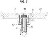
- the cylindrical electrode member (30) when the cylindrical electrode member (30) is pressed against the skin of a human body, the cylindrical electrode member (30) can be moved along the guide rod by the resilient member (20) according to the curvature of the skin. Accordingly, the depths of the cylindrical electrode members that are attached to the skin can be set to be a certain value. This can avoid a prior art problem that impedance was not be able to be measured precisely since the depths of electrode devices attached to the skin are not constant.
- the reference number 100 refers to a base plate in which electrode devices according to the present invention are mounted.
- FIG. 8 is a perspective view of an apparatus for measuring impedance of a human body according to a first embodiment of the present invention
- FIG. 9 is a perspective view of the bottom of the apparatus of FIG. 8
- the apparatus according to the first embodiment comprises a base plate (100) and a plurality of electrode devices (200).
- the base plate (100) has a plurality of electrode holes (110) and a plurality of first needle holes (120).
- the electrode holes (100) are arranged in an X-Y lattice structure.
- the first needle holes (120) are arranged in an X-Y lattice structure such that they are arranged with the electrode holes (100) alternately.
- the electrode devices each are mounted in the respective electrode holes (110).
- the electrode devices are connected to a plurality of first and second electrical lines (300, 310), which will be described in detail with reference to FIG. 21 .
- the base plate (100) can be made of any soft material that can make the base plate curved according to the curvature of the skin of a human body. As an example, it can be made of silicone.
- the distance between two adjacent electrode holes and the distance between two adjacent first needle holes are not limited to a specific value.
- the distances can be set in a range of 5mm to 20mm.
- the width of the first needle holes each is not limited to a specific value. It can be appropriately set according to the kind of a needle and/or the purpose of acupuncture.
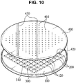
- FIG. 10 is a perspective view showing the apparatus of FIG. 8 comprising an examplary cover
- FIG. 11 is a perspective view showing the bottom of the apparatus comprising the cover.
- the exemplary cover (400) as shown in FIGS. 10 and 11 , is configured to be engaged with the base plate (100) to protect the electrode devices (200) and the first and second electrical lines (300, 310).
- the cover (400) has a plurality of second needle holes (410).
- the second needle holes (410) are arranged in the cover (400) such that the respective second needle holes (410) can be positioned over the respective first needle holes (120) of the base plate (100) when the cover (400) is engaged with the base plate (100).
- the second needle holes can be designed to have the same width as the first needle holes.
- the second needle holes (410) can be designed such that the ourter width is greater than the inner width, which makes it easier for a user to insert a needle to the second needle holes (410).
- at least one identifying member (430) may be provided on the cover (400) to make it easier for a user to handle the cover (400).
- the cover (400) can be made of any material that can perform the above-described function. As an example, it can be made of silicone.
- the cover (400) is provided with a connecting hole (420) through which electrical lines can be connected.
- FIG. 13 is perspective view showing the apparatus of FIG. 8 comprising another examplary cover.
- the cover (500) is in the form of a hemisphere.
- the cover (500) has a plurality of second needle holes (510).
- the second needle holes (510) are arranged in the cover (500) such that the respective second needle holes (510) can be positioned over the respective first needle holes (120) of the base plate (100) when the cover (500) is engaged with the base plate (100).
- the base plate (100) is designed to be flexible so as to become curved according to the curvature of the skin, as shown in FIG. 17 while the base plate (100) is flat in normal condition, as shown in FIG. 16 .
- FIG. 16 is a plurality of second needle holes
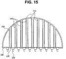
- the cover (500) has a plurality of guide hole members (540) each connecting the first needle holes (120) and the second needle holes (510) to make it easier for a user to handle a needle.
- the second needle holes (510) can be designed such that the outer width is greater than the inner width, which makes it easier for a user to insert a needle to the second needle holes (510).
- the cover (500) can be made of any material that can perform the above-described function. As an example, it can be made of silicone.
- the cover (500) is provided with a connecting hole (520) through which electrical lines can be connected.
- at least one identifying member (530) may be provided on the cover (500) to make it easier for a user to handle the cover (500).
- FIGS. 14 and 18 are perspective views showing the apparatus of FIG. 8 comprising another examplary cover and FIG. 19 is a perspective view showing the bottom of the apparatus comprising the cover shown in FIG. 18 .
- the cover (600) is in the form of a cylinder.
- the cover (600) has a plurality of second needle holes (610).
- the second needle holes (610) are arranged in the cover (600) such that the respective second needle holes (610) can be positioned over the respective first needle holes (120) of the base plate (100) when the cover (600) is engaged with the base plate (100).
- the base plate (100) is designed to be flexible so as to become curved according to the curvature of the skin, as shown in FIG.
- the cover (500) has a plurality of guide hole members (640) connecting the first needle holes (120) and the second needle holes (610) to make it easier for a user to handle a needle.
- the second needle holes (610) can be designed such that the outer width is greater than the inner width, which makes it easier for a user to insert a needle to the second needle holes (610).
- the cover (600) can be made of any material that can perform the above-described function. As an example, it can be made of silicone.
- the cover (600) is provided with a connecting hole (620) through which electrical lines can be connected.
- at least one identifying member (630) may be provided on the cover (600) to make it easier for a user to handle the cover (600).
- FIG. 21 shows electrode devices and electrical lines of an apparatus according to the first embodiment of the present invention.
- the electrode devices (200) and the first needle holes (120) are positioned on the base plate (100) such that they are alternating with each other.
- the first electrical lines (300) are formed between the respective electrode devices (200) and the respective first needle holes (120) in the direction of X-axis.
- the second electrical lines (310) are formed between the respective electrode devices (200) and the respective first needle holes (120) in the direction of Y-axis.
- the respective first and second electrical lines (300, 310) are connected to the respective electrode devices (200). Current is allowed to flow through the X-axis and Y-axis sequentially to measure impedances. For example, with the second vertical line S2 as an input electrode and the first horizontal line R1 as a receiving electrode, the impedance of the first horizontal needle hole H1 can be measured. Also, with the first vertical line S1 as an input electrode and the second horizontal line R2 as a receiving electrode, the impedance of the first vertical needle hole V1 can be measured.
- impedances can be measured sequentially with regard to all of the vertical and horizontal needle holes of the base plate (100).
- the measured impedances can be displayed as a 3-dimensional image by being coupled with CT or MRI devices.
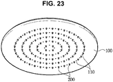
- FIG. 22 is a perspective view of an apparatus according to the second embodiment of the present invention and FIG. 23 is a perspective view of the bottom of the apparatus of FIG. 22 .
- the apparatus according to the second embodiment comprises a circular base plate (100) and a plurality of electrode devices (200).
- the circular base plate (100) includes a plurality of electrode hoes (110) and a plurality of first needle holes (120).
- the electrode holes (110) and first needle holes (120) are formed eccentrically and alternately, as shown in FIG. 22 .
- the electrode devices (200) are mounted to the electrode holes (110) and connected to a first and second electrical lines (300, 310)
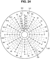
- FIG. 24 shows electrode devices and electrical lines of the apparatus of FIG. 22 .
- the first and second electrical lines (300, 310) are connected to the electrode devices alternately. Current is allowed sequentially to measure impedances.
- the impedances of the first, third, fifth, and seventh needle holes H1, H3, H5, and H5 can be measured.
- the impedances of the second, fourth, and sixth needle holes H2, H4, and H6 can be measured.
- the impedances can be measured sequentially with regard to all of needle holes of the base plate (100).
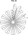
- FIG. 25 is a plane view of an apparatus according the third embodiment of the present invention.
- a base plate (100) has multiple parts that are provided radially with a predetermined distance between two adjacent parts. Each of the parts has a plurality of electrode holes and a plurality of first needle holes (120). The electrode holes and the first needle holes are mounted alternately. Current is allowed sequentially to measure impedances. For example, with the first input line S1 as an input electrode and the first receiving line R1 as a receiving electrode, the impedance of the first needle hole H1 can be measured. Also, with the second input line S2 as an input electrode and the first receiving line R1 as a receiving electrode, the impedance of the second needle hole H2 can be measured. Accordingly, if current is allowed to flow sequentially, the impedances can be measured sequentially with regard to all of needle holes of the base plate (100).
- FIG. 26 is a plane view of an apparatus according the fourth embodiment of the present invention.
- the apparatus comprises a base plate, a plurality of electrode devices, and first and second electrical lines.
- the base plate has a plurality of radial holes provided radially with a predetermined distance between two adjacent holes.
- the base plate has a plurality of electrode holes and a plurality of first needle holes between two adjacent radial holes.
- the electrode holes and the first needle holes are mounted alternately.
- the electrode devices are mounted to the electrode holes.
- the first and second electrical lines are connected to the electrode devices alternately.
Landscapes
- Health & Medical Sciences (AREA)
- Life Sciences & Earth Sciences (AREA)
- Nuclear Medicine, Radiotherapy & Molecular Imaging (AREA)
- Engineering & Computer Science (AREA)
- Medical Informatics (AREA)
- Physics & Mathematics (AREA)
- Biophysics (AREA)
- Public Health (AREA)
- Biomedical Technology (AREA)
- Heart & Thoracic Surgery (AREA)
- Radiology & Medical Imaging (AREA)
- Molecular Biology (AREA)
- Surgery (AREA)
- Animal Behavior & Ethology (AREA)
- General Health & Medical Sciences (AREA)
- Pathology (AREA)
- Veterinary Medicine (AREA)
- Dermatology (AREA)
- Pain & Pain Management (AREA)
- High Energy & Nuclear Physics (AREA)
- Optics & Photonics (AREA)
- Measurement And Recording Of Electrical Phenomena And Electrical Characteristics Of The Living Body (AREA)
- Finger-Pressure Massage (AREA)
Description
- The present disclosure relates to an apparatus for measuring impedance of a subject including human and treating certain conditions of the subject. More particularly, it relates to an apparatus for measuring impedance of a human body and treating a certain condition of a human body, which can precisely and automatically locate acupuncture points of a human body, display the location as a three-dimensional image, and facilitate acupuncture treatment using the located/displayed actupuncture points.
- Acupuncture treats certain conditions of a human body (e.g., brain) by physically (e.g., mechanically or electrically) stimulating acupuncture points of the human body to change certain functions of the human body. The acupuncture's treating effects vary depending on whether the acupuncture points are precisely located. Practitioners locate the acupuncture points by their past experience and personal technique.
- Electrical Impedance Tomography (EIT) was recently proposed and has been used as a medical imaging technique for some reasons. First, hardware systems using EIT are not expensive. Second, EIT is non-destructive and safe to a subject (e.g., human body). Third, temporal resolution provided by EIT is greater than those provided by X-ray or MRI while the spatial resolution of retrieved images is lower.
- Acupuncture points of a human body are two-dimensional anatomically. Different human bodies have different distribution patterns of nerve tissues and soft tissues. Locating acupuncture points of a human body thus tends to rely on medical professionals' experience. EIT analyzes acupuncture points of a human body from the perspective of engineering.
- According to EIT, a few milivolts of electric current at 10 to 100kHz are allowed to flow through a human body and a resistance of the human body in response to the electric current is measured. Acupuncture points of a human body have an impedance lower than that of tissues surrounding the acupuncture points. To find out the electrical characteristics of cross-sections of a human body, a plurality of electrodes are attached to a human body, a certain level of electric current is allowed to flow through the human body in a predetermined order, resistance data in response to the electric current is measured, and the resistance data is displayed as an image.
- A prior art electrical impedance tomography is described with reference to the drawings.
FIGS. 1 to 4 show the principle of imaging resistance data of a human body in the prior art electrical impedance tomography. - A plurality of electrodes are attached to a human body. Electric current is allowed to flow through the human body sequentially. Resulting resistance data is measured and displayed as an image. As shown in
FIG. 1 , for example, 2 x 2 of input electrodes (S, s) and receiving electrodes (R, r) are attached to a human body, electric current is allowed to flow, and resulting resistance is measured. - In detail, as shown in
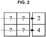
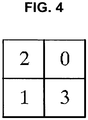
FIG. 1 , parallel input electrodes (S1, S2), parallel receiving electrodes (R1, R2), vertical input electrodes (s1, s2), and vertical receiving electrodes (r1, r2) are attached to a subject. As shown inFIG. 2 , electric current is then allowed to flow from the parallel input electrodes (S1, S2) to the parallel receiving electrodes (R1, R2) and impedance in the horizontal direction is measured. As shown inFIG. 3 , electric current is allowed to flow from the vertical input electrodes (s1, s2) to the vertical receiving electrodes (r1, r2) and impedance in the vertical direction is measured. As a result, as shown inFIG. 4 , distribution of impedances of a human body can be estimated by reverse non-linear data processing. - Typically, an EIT apparatus has cylindrical electrodes that are designed to be attached to the skin of a human body by, for example, surrounding the skin (e.g., ankle, wrist, and the like). After the electrodes are attached to the skin, electrical current is allowed to flow through the human body sequentially and resulting resistances are measured. For example, the measured vertical and horizontal resistance values are the sum of all resistances of the body. Distribution of resistance data with regard to a certain cross-section of the body can be detected. Alternatively, from a known resistance distribution data, voltage distribution can be calculated according to the strength of the current, thereby being able to display an equipotential line.
- The prior art EIT apparatus, however, has the following problems.
- First, as skeletons of a human body are imaged, it takes a lont time to perform data processing.
- Second, depending on how the electrodes are attached to a human body, resolution of the image of acupuncture points can be seginificantly low.
- Third, although acupuncture points can be real-time detected, acupunctural treatment cannot be performed using the detected points.
- Prior
art document GB 2 115 700 A - Prior art document
US 2009/0156925 A1 discloses an active sensor module for the measurement of bioelectricity. The sensor module comprises an active electrode which is inserted in an opening of a cap and which abuts by means of a protrusion at an inner surface of the cap. The electrode is biased by a spring which is situated between an end of the electrode opposing the contact surface and an inner wall of a main body. - Prior
art document GB 2 318 642 A - Document
US 6,181,974 B1 concerns a facial contact electrode wherein the electrodes is formed by his crew screwed into a cylindrical housing which resides between an assembly of inner and outer liners. - It is an object underlying the present invention to provide an electrode device for measuring impedances of a human body and an apparatus for measuring the impedance of a human body which allow a more reliable and less time consuming measurement with a higher accuracy.
- To solve the above-described problems, the present invention provides an electrode device for measuring impedances of a human body and an apparatus comprising the electrode device. The electrode device and the apparatus can automatically and precisely locate acupuncture points (meridians) of a human body, display the points as a three-dimensional image, and allow a precise acupuncture treatment to be performed at a desired location.
- The objects underlying the present invention are achieved by an electrode device according to independent claim 1 and by an apparatuses according to
independent claims 6 and 15. Preferred embodiments are defined and the respect of dependent claims. - In one aspect, the present invention provides an electrode device for measuring impedances of a human body, comprising: a cylindrical housing member having a guide rod mounted to an open side thereof; a cylindrical electrode member configured to be pressed against the skin of a human body and moved back and forth through the open side along the guide rod; and a resilient member interposed between the cylindrical electrode member and the cylindrical housing member to resiliently move the cylindrical electrode member back and forth along the guide rod.
- In some embodiments, the cylindrical electrode member is an electrode made of a conductive material or an electrode coated with a conductive material. The conductive material may be, e.g., gold.
- In some embodiments, a protruding portion is formed at the open end of the cylindrical electrode member such that engagement between the cylindrical electrode member and the cylindrical housing member is facilitated.
- In some embodiments, the cylindrical housing member is made of a conductive material or an electrode coated with a conductive material.
- In some embodiments, a first housing protruding portion is formed at the open side of the cylindrical housing member and a second housing protruding portion is formed at the other side of the cylindrical housing member.
- In some embodiments, the resilient member is made of a conductive material. The resilient member may be a spring, for example.
- In another aspect, the present invention provides an apparatus for measuring impedance of a human body, which comprises: a base plate having a plurality of electrode holes formed in a lattice structure and a plurality of a first needle holes formed in a lattice structure such that the electrode holes and the first needle holes are arranged alternately; a plurality of electrodes mounted to the electrode holes; and first and second electrical lines connected to the electrodes.
- In some embodiments, the distance between two adjacent electrode holes and the distance between two adjacent first needle holes are set in a range of 5mm to 20mm.
- In some embodiments, the apparatus may further comprise a cover configured to be engaged with the base plate to protect the electrodes and the first and second electrical lines. Preferably, the cover may include a plurality of second needle holes arranged such that the respective second needle holes can be positioned over the respective first needle holes of the base plate when the cover is engaged with the base plate. Preferably, the outer width of the second needle holes may be designed to be greater than the inner width thereof.
- In some embodiments, the cover is provided with at least one identifying member. Preferably, the cover may be made of silicone.
- In some embodiments, the cover may be shaped to be a hemisphere or a cylinder. Preferably, the cover may further comprise a plurality of guide hole members each connecting the first needle holes and the second needle holes.
- In some embodiments, the first electrical lines are formed between the respective electrodes and the respective first needle holes in the direction of X-axis and the second electrical lines are formed between the respective electrodes and the respective first needle holes in the direction of Y-axis.
- In some embodiments, the first electrical lines are connected to input electrodes and the second electrical lines are connected to receiving electrodes.
- In another aspect, the present inventions provides an apparatus for measuring impedances of a human body, comprising: a circular base plate including a plurality of electrode hoes and a plurality of first needle holes, the electrode holes and the first needle holes being formed eccentrically and alternately; a plurality of electrodes mounted to the electrode holes; and first and second electrical lines connected to the electrodes. Preferably, the first electrical lines and the second electrical lines may be connected to the electrodes alternately.
- In still another aspect, the present invention provides an apparatus for measuring impedances of a human body, comprising: a base plate having a plurality of parts that are provided radially with a predetermined distance between two adjacent parts, each of which parts has a plurality of electrode holes and a plurality of first needle holes, the electrode holes and the first needle holes being mounted alternately; a plurality of electrodes mounted to the electrode holes; and first and second electrical lines connected to the electrode holes alternately. Preferably, the first electrical lines may be connected to input electrodes and the second electrical lines are connected to receiving electrodes.
- In yet another aspect, the present invention provides an apparatus for measuring impedances of a human body, comprising: a base plate having a plurality of parts that are provided radially with a predetermined distance between two adjacent parts, each of which parts has a plurality of electrode holes and a plurality of first needle holes, the electrode holes and the first needle holes being mounted alternately with respect to the center of base plate; a plurality of electrode devices mounted to the electrode holes; and first and second electrical lines connected to the electrode holes alternately. Preferably, the first electrical lines may be connected to input electrodes and the second electrical lines are connected to receiving electrodes.
- In a further aspect, the present invention provides an apparatus for measuring impedances of a human body, comprising: a base plate having a plurality of radial holes provided radially with a predetermined distance between two adjacent holes, the base plate having a plurality of electrode holes and a plurality of first needle holes between two adjacent radial holes; a plurality of electrode devices mounted to the electrode holes; and first and second electrical lines connected to the electrode devices alternately, wherein the electrode holes and the first needle holes are mounted alternately with respect to the center of base plate. Preferably, the first electrical lines may be connected to input electrodes and the second electrical lines are connected to receiving electrodes.
- The present invention provides advantageous effects including the following. First, the data about the location of acupuncture points can be easily and quickly obtained. Second, acupuncture points can be located precisely regardless of curvature of the skin of a human body. Third, acupuncture points can be located and displayed without decrease in resolution regardless of the skin to be contacted by the apparatus. Fourth, the data about acupuncture points can be displayed as a three-dimensional image in combination with CT or MRI devices. Fifth, acupuncture points can be located automatically and acupuncture treatment can be performed according to the located points, which allow a user even without sufficient experience to use the apparatus.
-
-
FIGS. 1 to 4 illustrate the principle of displaying resistance of a human body as an image according to a conventional electrical impedance tomography. -
FIG. 5 is a cross-sectional view showing a dissembled state of an electrode device for measuring impedance of a human body according to the first embodiment of the present invention. -
FIG. 6 is a cross-sectional view showing an assembled state of the electrode device ofFIG. 5 . -
FIG. 7 is a cross-sectional view showing an example of application of the electrode device ofFIG. 5 . -
FIG. 8 is a perspective view of an apparatus for measuring impedance of a human body according to the first embodiment of the present invention. -
FIG. 9 is a perspective view of the bottom of the apparatus ofFIG. 8 . -
FIG. 10 is a perspective view showing the apparatus ofFIG. 8 comprising an an examplary cover. -
FIG. 11 is a perspective view showing the bottom of the the apparatus ofFIG. 8 comprsing an exemplary cover. -
FIG. 12 is an enlarged view showing a hole of the cover ofFIGS. 10 and11 . -
FIG. 13 is a perspective view showing the apparatus ofFIG. 8 comprising another examplary cover. -
FIG. 14 is a perspective view showing the apparatus ofFIG. 8 comprising a still another examplary cover. -
FIG. 15 is an enlarged view showing a guide hole member of the covers ofFIG. 13 and14 . -
FIGS. 16 and 17 illustrate that an apparatus according to the present invention has flexibility. -
FIG. 18 is a perspective view showing the apparatus ofFIG. 8 comprising a still further examplary cover. -
FIG. 19 is a perspective view showing the bottom of the apparatus ofFIG. 18 comprising a still further examplary cover. -
FIG. 20 is an enlarged view showing a guide hole member of the covers ofFIG. 18 and19 . -
FIG. 21 shows electrode devices and electrical lines of an apparatus according to the first embodiment of the present invention. -
FIG. 22 is a perspective view of an apparatus for measuring impedance of a human body according to the second embodiment of the present invention. -
FIG. 23 is a perspective view of the bottom of the apparatus ofFIG. 22 . -
FIG. 24 shows electrode devices and electrical lines of the apparatus ofFIG. 22 . -
FIG. 25 is a plane view of an apparatus according the third embodiment of the present invention. -
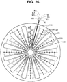
FIG. 26 is a plane view of an apparatus according the fourth embodiment of the present invention. - Reference numerals set forth in the Drawings includes reference to the following elements as further discussed below:
10: housing member 11: guide rod 20: resilient member 30: cylindrical electrode member 100: base plate 110: electrode hole 120: first needle hole 130: radial hole 200: electrode device 300, 310: electrical lines 400, 500, 600: cover 410, 510, 610: second needle hole 420, 520, 620: connecting hole 430, 530, 630: identifying member - Reference will now be made in detail to the preferred embodiment of the present invention, examples of which are illustrated in the drawings attached hereinafter, wherein like reference numerals refer to like elements throughout. The embodiments are described below so as to explain the present invention by referring to the figures.
- Terms used herein are those used generally in the art unless otherwise being defined herein, in which case such terms are described in the specification and they should be construed by replying on the description. Also, detailed description of the subject matter that is known to those skilled in the art and is not directly related to the present invention is omitted for simplicity.
-
FIG. 5 is a cross-sectional view showing a dissembled state of an electrode device for measuring impedance of a human body according to the first embodiment of the present invention andFIG. 6 is a cross-sectional view showing an assembled state of the electrode device ofFIG. 5 . - The electrode device according to the first embodiment, as shown in
FIGS. 5 and6 , comprises a cylindrical housing member (10), a cylindrical electrode member (20), and a resilient member (30). The cylindrical housing member (10) has a guide rod (11) mounted to an open side thereof. The cylindrical electrode member (30) is configured to be pressed against the skin of a human body to move back and forth through the open side along the guide rod (11). The resilient member (30) is interposed between the cylindrical electrode member (20) and the cylindrical housing member (10) to resiliently move the cylindrical electrode member (20) back and forth. - The cylindrical electrode member (30) can be an electrode made of a conductive material. It can also be an electrode coated with a conductive material. Any material that shows conductivity can be used as the conductive material. Preferably, the conductive material is non-toxic to a human body. As an example, an electrode made of a gold or an electrode coated with gold can be used. The cylindrical electrode member (30) has an open end. A protruding portion (31) is formed at the open end of the cylindrical electrode member (30). The protruding portion (31) may be formed in any shape that can facilitate engagement between the cylindrical electrode member (30) and the cylindrical housing member (10).
- The cylindrical housing member (10) can be made of a conductive material. It can also be an electrode coated with a conductive material. Any material that shows conductivity can be used as the conductive material. As an example, an electrode made of gold or an electrode coated with gold can be used. Also, a copper wire or an iron wire can be used. A first protruding portion (12) is formed at the open side of the cylindrical housing member (10). The first housing protruding portion (12) is formed in any shape that can facilitate engagement between the cylindrical electrode member (30) and the cylindrical housing member (10). A second housing portion (13) is formed at the other side of the cylindrical housing member (10).
- The resilient member (20) can be made of any material that can show resilient features. The resilient material can also be a conductive material. As an example, a spring can be used.
-
FIG. 7 is a cross-sectional view showing an example of application of the electrode device ofFIG. 5 . As shown inFIG. 7 , when the cylindrical electrode member (30) is pressed against the skin of a human body, the cylindrical electrode member (30) can be moved along the guide rod by the resilient member (20) according to the curvature of the skin. Accordingly, the depths of the cylindrical electrode members that are attached to the skin can be set to be a certain value. This can avoid a prior art problem that impedance was not be able to be measured precisely since the depths of electrode devices attached to the skin are not constant. Thereference number 100 refers to a base plate in which electrode devices according to the present invention are mounted. -
FIG. 8 is a perspective view of an apparatus for measuring impedance of a human body according to a first embodiment of the present invention, andFIG. 9 is a perspective view of the bottom of the apparatus ofFIG. 8 . As shown inFIGS. 8 and9 , the apparatus according to the first embodiment comprises a base plate (100) and a plurality of electrode devices (200). The base plate (100) has a plurality of electrode holes (110) and a plurality of first needle holes (120). The electrode holes (100) are arranged in an X-Y lattice structure. The first needle holes (120) are arranged in an X-Y lattice structure such that they are arranged with the electrode holes (100) alternately. The electrode devices each are mounted in the respective electrode holes (110). The electrode devices are connected to a plurality of first and second electrical lines (300, 310), which will be described in detail with reference toFIG. 21 . The base plate (100) can be made of any soft material that can make the base plate curved according to the curvature of the skin of a human body. As an example, it can be made of silicone. - The distance between two adjacent electrode holes and the distance between two adjacent first needle holes are not limited to a specific value. Preferably, the distances can be set in a range of 5mm to 20mm.
- The width of the first needle holes each is not limited to a specific value. It can be appropriately set according to the kind of a needle and/or the purpose of acupuncture.
-
FIG. 10 is a perspective view showing the apparatus ofFIG. 8 comprising an examplary cover andFIG. 11 is a perspective view showing the bottom of the apparatus comprising the cover. The exemplary cover (400), as shown inFIGS. 10 and11 , is configured to be engaged with the base plate (100) to protect the electrode devices (200) and the first and second electrical lines (300, 310). The cover (400) has a plurality of second needle holes (410). The second needle holes (410) are arranged in the cover (400) such that the respective second needle holes (410) can be positioned over the respective first needle holes (120) of the base plate (100) when the cover (400) is engaged with the base plate (100). The second needle holes can be designed to have the same width as the first needle holes. Preferably, as shown inFIG. 12 , the second needle holes (410) can be designed such that the ourter width is greater than the inner width, which makes it easier for a user to insert a needle to the second needle holes (410). In some embodiments, at least one identifying member (430) may be provided on the cover (400) to make it easier for a user to handle the cover (400). The cover (400) can be made of any material that can perform the above-described function. As an example, it can be made of silicone. The cover (400) is provided with a connecting hole (420) through which electrical lines can be connected. -
FIG. 13 is perspective view showing the apparatus ofFIG. 8 comprising another examplary cover. As shown inFIG. 13 , the cover (500) is in the form of a hemisphere. The cover (500) has a plurality of second needle holes (510). The second needle holes (510) are arranged in the cover (500) such that the respective second needle holes (510) can be positioned over the respective first needle holes (120) of the base plate (100) when the cover (500) is engaged with the base plate (100). In some embodiments, the base plate (100) is designed to be flexible so as to become curved according to the curvature of the skin, as shown inFIG. 17 while the base plate (100) is flat in normal condition, as shown inFIG. 16 . In some embodiments, as shown inFIG. 15 , the cover (500) has a plurality of guide hole members (540) each connecting the first needle holes (120) and the second needle holes (510) to make it easier for a user to handle a needle. As described above, preferably, the second needle holes (510) can be designed such that the outer width is greater than the inner width, which makes it easier for a user to insert a needle to the second needle holes (510). The cover (500) can be made of any material that can perform the above-described function. As an example, it can be made of silicone. The cover (500) is provided with a connecting hole (520) through which electrical lines can be connected. In some embodiments, at least one identifying member (530) may be provided on the cover (500) to make it easier for a user to handle the cover (500). -
FIGS. 14 and18 are perspective views showing the apparatus ofFIG. 8 comprising another examplary cover andFIG. 19 is a perspective view showing the bottom of the apparatus comprising the cover shown inFIG. 18 . As shown in the drawings, the cover (600) is in the form of a cylinder. The cover (600) has a plurality of second needle holes (610). The second needle holes (610) are arranged in the cover (600) such that the respective second needle holes (610) can be positioned over the respective first needle holes (120) of the base plate (100) when the cover (600) is engaged with the base plate (100). In some embodiments, the base plate (100) is designed to be flexible so as to become curved according to the curvature of the skin, as shown inFIG. 17 while the base plate (100) is flat in normal condition, as shown inFIG. 16 . In some embodiments, as shown inFIG. 20 , the cover (500) has a plurality of guide hole members (640) connecting the first needle holes (120) and the second needle holes (610) to make it easier for a user to handle a needle. As described above, preferably, the second needle holes (610) can be designed such that the outer width is greater than the inner width, which makes it easier for a user to insert a needle to the second needle holes (610). The cover (600) can be made of any material that can perform the above-described function. As an example, it can be made of silicone. The cover (600) is provided with a connecting hole (620) through which electrical lines can be connected. In some embodiments, at least one identifying member (630) may be provided on the cover (600) to make it easier for a user to handle the cover (600). -
FIG. 21 shows electrode devices and electrical lines of an apparatus according to the first embodiment of the present invention. The electrode devices (200) and the first needle holes (120) are positioned on the base plate (100) such that they are alternating with each other. The first electrical lines (300) are formed between the respective electrode devices (200) and the respective first needle holes (120) in the direction of X-axis. The second electrical lines (310) are formed between the respective electrode devices (200) and the respective first needle holes (120) in the direction of Y-axis. - The respective first and second electrical lines (300, 310) are connected to the respective electrode devices (200). Current is allowed to flow through the X-axis and Y-axis sequentially to measure impedances. For example, with the second vertical line S2 as an input electrode and the first horizontal line R1 as a receiving electrode, the impedance of the first horizontal needle hole H1 can be measured. Also, with the first vertical line S1 as an input electrode and the second horizontal line R2 as a receiving electrode, the impedance of the first vertical needle hole V1 can be measured. Accordingly, if current is allowed to flow from the first vertical line S1 to the eleventh vertical line S11 sequentially to act as input electrodes and from the horizontal line R1 to the eleventh horizontal line R11 to act as receiving electrodes, impedances can be measured sequentially with regard to all of the vertical and horizontal needle holes of the base plate (100). The measured impedances can be displayed as a 3-dimensional image by being coupled with CT or MRI devices.
-
FIG. 22 is a perspective view of an apparatus according to the second embodiment of the present invention andFIG. 23 is a perspective view of the bottom of the apparatus ofFIG. 22 . As shown inFIGS. 22 and23 , the apparatus according to the second embodiment comprises a circular base plate (100) and a plurality of electrode devices (200). The circular base plate (100) includes a plurality of electrode hoes (110) and a plurality of first needle holes (120). The electrode holes (110) and first needle holes (120) are formed eccentrically and alternately, as shown inFIG. 22 . The electrode devices (200) are mounted to the electrode holes (110) and connected to a first and second electrical lines (300, 310) -
FIG. 24 shows electrode devices and electrical lines of the apparatus ofFIG. 22 . The first and second electrical lines (300, 310) are connected to the electrode devices alternately. Current is allowed sequentially to measure impedances. For example, with the second input line S2 as an input electrode and the twelveth receiving line R12 as a receiving electrode, the impedances of the first, third, fifth, and seventh needle holes H1, H3, H5, and H5 can be measured. Also, with the first input line S1 as an input electrode and the first receiving line R1 as a receiving electrode, the impedances of the second, fourth, and sixth needle holes H2, H4, and H6 can be measured. Accordingly, if current is allowed to flow from the first input line S1 to the twelveth input line S12 and from the first receiving line R1 to the twelveth receiving line R12 sequentially to act as input electrodes and receiving electrodes, respectively, the impedances can be measured sequentially with regard to all of needle holes of the base plate (100). -
FIG. 25 is a plane view of an apparatus according the third embodiment of the present invention. In this embodiment, a base plate (100) has multiple parts that are provided radially with a predetermined distance between two adjacent parts. Each of the parts has a plurality of electrode holes and a plurality of first needle holes (120). The electrode holes and the first needle holes are mounted alternately. Current is allowed sequentially to measure impedances. For example, with the first input line S1 as an input electrode and the first receiving line R1 as a receiving electrode, the impedance of the first needle hole H1 can be measured. Also, with the second input line S2 as an input electrode and the first receiving line R1 as a receiving electrode, the impedance of the second needle hole H2 can be measured. Accordingly, if current is allowed to flow sequentially, the impedances can be measured sequentially with regard to all of needle holes of the base plate (100). -
FIG. 26 is a plane view of an apparatus according the fourth embodiment of the present invention. In this embodiment, the apparatus comprises a base plate, a plurality of electrode devices, and first and second electrical lines. The base plate has a plurality of radial holes provided radially with a predetermined distance between two adjacent holes. The base plate has a plurality of electrode holes and a plurality of first needle holes between two adjacent radial holes. The electrode holes and the first needle holes are mounted alternately. The electrode devices are mounted to the electrode holes. The first and second electrical lines are connected to the electrode devices alternately. As the principle of measuring impedances is similar to the principle described with regard toFIG. 25 , detailed description thereof is omitted. - The foregoing descriptions of specific exemplary embodiments of the present invention have been presented for purposes of illustration and description. They are not intended to be exhaustive or to limit the invention to the precise forms disclosed, and obviously many modifications and variations are possible in light of the above teachings. The exemplary embodiments were chosen and described in order to explain certain principles of the invention and their practical application, to thereby enable others skilled in the art to make and utilize various exemplary embodiments of the present invention, as well as various alternatives and modifications thereof. It is intended that the scope of the invention be defined by the Claims appended hereto.
Claims (15)
- An electrode device (200) for measuring impedances of a human body, comprising:- a housing member (10) having an open side;- a guide rod (11) that has first and second ends, that extends from an inner surface of the cylindrical housing member (10) such that the first end of the guide rod (11) is disposed at the inner surface, and that extends through the open side of the cylindrical housing member (10);- a cylindrical electrode member (30) having an open end and configured to be pressed against the skin of a human body to move back and forth through the open side of the cylindrical housing member (10) along the guide rod (11);
the cylindrical electrode member (30) being disposed around the guide rod (11) and the cylindrical electrode member (30) having a protruding portion (31) formed at the open end thereof that allows the cylindrical electrode member (30) to engage with the cylindrical housing member (10); and- a spring (20) surrounding the guide rod (11) and interposed between the top of the cylindrical electrode member (30) and the top of the cylindrical housing member (10) to resiliently move the cylindrical electrode member (10) back and forth along the guide rod (11), the electrode device characterised in that:- the housing member is a cylindrical housing member- the spring (20) abuts against the protruding portion (31) at the open end of the cylindrical electrode member (30)- a first housing protruding portion (12) is formed at the open side of said cylindrical housing member (10) such that engagement between the cylindrical electrode member (30) and said cylindrical housing member (10) is facilitated, and- a second housing protruding portion (13) is formed at an other side of said cylindrical housing member (10) such that engagement between said cylindrical housing member (10) and a base plate (100) is facilitated. - The electrode device (200) of claim 1,- wherein the cylindrical electrode member (30) is an electrode made of a conductive material or an electrode coated with a conductive material,- wherein in particular the conductive material is gold.
- The electrode device (200) of claim 1,
wherein the cylindrical housing member (10) is made of a conductive material or an electrode coated with a conductive material. - The electrode device (200) of claim 1,
wherein said first housing protruding portion (12) is formed at the open side of the cylindrical housing member (10) and said second housing protruding portion (13) is formed at the other side of the cylindrical housing member (10). - The electrode device (200) of claim 1,
wherein the resilient member (20) is made of a conductive material. - An apparatus for measuring impedance of a human body, which comprises:- a base plate (100) having a plurality of electrode holes (200) formed in a lattice structure and a plurality of a first needle holes (120) formed in a lattice structure such that the electrode holes (200) and the first needle holes (120) are arranged alternately;- a plurality of electrode devices according to any of the preceding claims mounted to the electrode holes; and- first and second electrical lines (300, 310) connected to the electrode devices.
- The apparatus of claim 6,
wherein the distance between two adjacent electrode holes (200) and the distance between two adjacent first needle holes (120) are set in a range of 5 mm to 20 mm. - The apparatus of claim 6,
further comprising a cover (400; 500) configured to be engaged with the base plate (100) to protect the electrode devices and the first and second electrical lines (300, 310). - The apparatus of claim 7,
wherein the cover includes a plurality of second needle holes (410) arranged such that the respective second needle holes (410) can be positioned over the respective first needle holes (120) of the base plate (100) when the cover (400; 500) is engaged with the base plate (100). - The apparatus of claim 9,
wherein the outer width of the second needle holes (410) is greater than the inner width thereof. - The apparatus of claim 8,- wherein the cover (400; 500) is provided with at least one identifying member and/or- wherein the cover (400; 500) is made of silicone and/or- wherein the cover (400; 500) is shaped to be a hemisphere or a cylinder.
- The apparatus of claim 11,
wherein the cover (500) further comprises a plurality of guide hole members (540) each connecting the first needle holes (120) and the second needle holes (400). - The apparatus of claim 6,
wherein the first electrical lines (300) are formed between the respective electrode devices and the respective first needle holes in the direction of X-axis and the second electrical lines (310) are formed between the respective electrode devices and the respective first needle holes in the direction of Y-axis. - The apparatus of claim 6,
wherein the first electrical lines (300) are connected to input electrodes and the second electrical lines (310) are connected to receiving electrodes. - An apparatus for measuring impedances of a human body, comprising:- a circular base plate (100) including a plurality of electrode holes (110) and a plurality of first needle holes (120), the electrode holes (110) and the first needle holes (120) being formed eccentrically and alternately;- a plurality of electrode devices (200) according to any of claims 1 to 5 mounted to the electrode holes (110); and- first and second electrical lines (300, 310) connected to the electrode devices (200).
Applications Claiming Priority (2)
| Application Number | Priority Date | Filing Date | Title |
|---|---|---|---|
| KR1020090113118A KR100965351B1 (en) | 2009-11-23 | 2009-11-23 | Apparatus for acupuncturing with measuring impedance in humanbody using electrode apparatus for measuring impedance in humanbody |
| PCT/KR2009/006953 WO2011062315A1 (en) | 2009-11-23 | 2009-11-25 | Electrode apparatus for measuring impedance within the human body, and apparatus using same for measuring impedance within the human body and performing treatment |
Publications (3)
| Publication Number | Publication Date |
|---|---|
| EP2505136A1 EP2505136A1 (en) | 2012-10-03 |
| EP2505136A4 EP2505136A4 (en) | 2015-01-21 |
| EP2505136B1 true EP2505136B1 (en) | 2017-06-14 |
Family
ID=42370325
Family Applications (1)
| Application Number | Title | Priority Date | Filing Date |
|---|---|---|---|
| EP09851500.0A Not-in-force EP2505136B1 (en) | 2009-11-23 | 2009-11-25 | Electrode apparatus for measuring impedance within the human body, and apparatus using same for measuring impedance within the human body and performing treatment |
Country Status (9)
| Country | Link |
|---|---|
| US (2) | US20130102872A1 (en) |
| EP (1) | EP2505136B1 (en) |
| JP (2) | JP5766709B2 (en) |
| KR (1) | KR100965351B1 (en) |
| CN (1) | CN102802518B (en) |
| AU (1) | AU2009355661A1 (en) |
| NZ (1) | NZ600217A (en) |
| PH (1) | PH12012501008A1 (en) |
| WO (1) | WO2011062315A1 (en) |
Families Citing this family (32)
| Publication number | Priority date | Publication date | Assignee | Title |
|---|---|---|---|---|
| KR101224124B1 (en) | 2010-12-27 | 2013-01-21 | 재단법인차세대융합기술연구원 | Low frequency stimulating method and low frequency stimulating system |
| US20130150696A1 (en) * | 2011-12-12 | 2013-06-13 | Huntington Medical Research Institutes | Hybrid multielectrode arrays |
| CN103054578B (en) * | 2013-01-24 | 2015-04-01 | 四川大学 | Meridian point search tester |
| KR101592925B1 (en) | 2013-11-29 | 2016-02-11 | 문찬곤 | Device for measuring bioelectrical signals and stimulating body using mesh structure |
| KR101490811B1 (en) | 2013-12-04 | 2015-02-06 | 주식회사 케이헬쓰웨어 | Electrical Impedance Tomography Apparatus |
| CN103654777B (en) * | 2013-12-09 | 2018-09-18 | 思澜科技(成都)有限公司 | Measure the device of organism electrical impedance |
| KR101572897B1 (en) | 2014-02-28 | 2015-11-30 | 주식회사 엠에스피 | Measuring device human body impedance |
| US20170065201A1 (en) * | 2014-02-28 | 2017-03-09 | Msp Co., Ltd | Human body impedance measurement device |
| KR101603762B1 (en) * | 2014-02-28 | 2016-03-15 | 주식회사 엠에스피 | Measuring device human body impedance having strain sensor |
| KR101603763B1 (en) | 2014-03-24 | 2016-03-15 | 주식회사 엠에스피 | Measuring device human body impedance and the method of obtaining images using the same |
| KR101603764B1 (en) * | 2014-03-25 | 2016-03-15 | 주식회사 엠에스피 | Measuring device human body impedance |
| CN104095631B (en) * | 2014-07-24 | 2023-05-26 | 思澜科技(成都)有限公司 | Biological impedance measuring probe based on four-electrode model |
| CN105747294B (en) * | 2015-04-13 | 2017-06-06 | 北京至感传感器技术研究院有限公司 | Chest pad, chest pad component and mammary tumor detection means |
| CN105286863A (en) * | 2015-06-25 | 2016-02-03 | 思澜科技(成都)有限公司 | Quick measuring device and quick measuring method on basis of bio-impedance technologies |
| CN105534695A (en) * | 2016-03-02 | 2016-05-04 | 潘君昂 | Acupuncture and moxibustion method automatically selecting acupuncture points |
| GB2553261B (en) * | 2016-05-31 | 2022-05-04 | Wang Wei | Electrical impedance measurement and EIT image for location of a micro bio-channel under skin |
| CN107088065B (en) * | 2017-05-03 | 2021-01-29 | 京东方科技集团股份有限公司 | Brain electricity electrode |
| US11278735B2 (en) * | 2017-05-10 | 2022-03-22 | FREMSLIFE S.r.l. | Laser-therapy device |
| CN107281638B (en) * | 2017-06-14 | 2021-04-30 | 深圳湾新科技有限公司 | Control method for acupuncture by using acupoint plaster |
| US10420505B2 (en) | 2017-07-18 | 2019-09-24 | Forest Devices, Inc. | Electrode array apparatus, neurological condition detection apparatus, and method of using the same |
| US20230337930A1 (en) * | 2018-02-28 | 2023-10-26 | Gense Technologies Limited | Electrical impedance tomography based medical screening system |
| CN112204501A (en) * | 2018-02-28 | 2021-01-08 | 陈维达 | Wearable gesture recognition device and related operation method and system |
| US11109787B2 (en) * | 2018-05-21 | 2021-09-07 | Vine Medical LLC | Multi-tip probe for obtaining bioelectrical measurements |
| CN108709909B (en) * | 2018-06-25 | 2023-06-30 | 中国地质大学(武汉) | An electrode device based on EIT non-destructive testing cement-based flat plate |
| US11324415B2 (en) * | 2018-10-22 | 2022-05-10 | Vine Medical LLC | Conductivity compensation factor for assessing bioelectric measurements |
| CN109745047B (en) * | 2019-01-22 | 2021-07-02 | 北京航空航天大学 | An electrical impedance imaging system based on piezoresistive electrodes |
| CN111529927B (en) * | 2020-04-09 | 2023-05-02 | 山东丝琳医药科技有限公司 | Medical medium frequency electrode pen |
| CN112472060B (en) * | 2020-11-19 | 2023-03-14 | 西安电子科技大学 | Human body periumbilical impedance measurement sensing assembly |
| CN112294286B (en) * | 2020-11-19 | 2023-04-25 | 西安电子科技大学 | A device for measuring human abdominal impedance |
| CN113143206B (en) * | 2021-02-23 | 2023-08-01 | 添可智能科技有限公司 | Nursing equipment, elasticity detection equipment and detection method |
| CN115005795B (en) * | 2022-07-15 | 2025-05-27 | 中国科学院电工研究所 | A three-dimensional imaging device and method for skin electrical characteristics of acupoint areas during acupuncture |
| US12053431B2 (en) * | 2022-08-19 | 2024-08-06 | Oriental Power Inc. | Automatic acupuncture robot |
Citations (1)
| Publication number | Priority date | Publication date | Assignee | Title |
|---|---|---|---|---|
| US6181974B1 (en) * | 1999-03-29 | 2001-01-30 | George E. Springer, Jr. | Facial contact electrode |
Family Cites Families (31)
| Publication number | Priority date | Publication date | Assignee | Title |
|---|---|---|---|---|
| US4550735A (en) * | 1980-12-31 | 1985-11-05 | Norio Akamatsu | Electrode for an electrocardiograph |
| CS228175B1 (en) * | 1982-02-26 | 1984-05-14 | Kocur Pavel Ing.,Cs | Contact electrode |
| US4967038A (en) * | 1986-12-16 | 1990-10-30 | Sam Techology Inc. | Dry electrode brain wave recording system |
| JP2711275B2 (en) * | 1988-02-29 | 1998-02-10 | 株式会社アムテックス | Acupoint exploration device |
| JPH058968Y2 (en) * | 1988-03-17 | 1993-03-05 | ||
| JPH03292959A (en) * | 1990-04-11 | 1991-12-24 | Aika:Kk | Acupuncture probe and acupuncture probing and stimulating apparatus |
| US5299572A (en) * | 1992-10-30 | 1994-04-05 | University Of British Columbia | Biological electrode array |
| JPH09201345A (en) * | 1996-01-29 | 1997-08-05 | Toshiba Corp | Bioimpedance measuring device |
| GB2318642A (en) * | 1996-10-26 | 1998-04-29 | Stephen Magee | Self-adjustiing electrode for sensing galvanic skin resistance |
| JP3056082U (en) * | 1998-07-22 | 1999-02-02 | 株式会社東和製作所 | Adhesive for fashion stimulation |
| US6280454B1 (en) * | 1999-12-10 | 2001-08-28 | Wei-Cheng Wang | Head acupuncture instrument |
| US6564079B1 (en) * | 2000-07-27 | 2003-05-13 | Ckm Diagnostics, Inc. | Electrode array and skin attachment system for noninvasive nerve location and imaging device |
| JP2004166934A (en) * | 2002-11-19 | 2004-06-17 | Eucalyptus:Kk | Body surface electrocardiograph |
| US20050013850A1 (en) * | 2003-07-15 | 2005-01-20 | Caers Jan K. | Device to assist hyperhydrosis therapy |
| KR20050072965A (en) * | 2004-01-08 | 2005-07-13 | 림스테크널러지주식회사 | Active dry sensor module for measurement of bioelectricity |
| US20080027345A1 (en) * | 2004-06-25 | 2008-01-31 | Olympus Corporation | Electrode Apparatus For Detecting Brain Waves And Package |
| US7865236B2 (en) * | 2004-10-20 | 2011-01-04 | Nervonix, Inc. | Active electrode, bio-impedance based, tissue discrimination system and methods of use |
| US8024022B2 (en) * | 2005-05-25 | 2011-09-20 | Alfred E. Mann Foundation For Scientific Research | Hermetically sealed three-dimensional electrode array |
| CN1739448A (en) * | 2005-08-04 | 2006-03-01 | 浙江大学 | Biological impedance, resistance or potential detecting electrode with dynamometer |
| CN2902191Y (en) * | 2006-01-25 | 2007-05-23 | 中国医学科学院生物医学工程研究所 | Electrode array sensor used for electrical impedance imaging |
| TW200740410A (en) * | 2006-03-22 | 2007-11-01 | Emotiv Systems Pty Ltd | Electrode and electrode headset |
| ES2409734T3 (en) * | 2006-12-08 | 2013-06-27 | Fraunhofer-Gesellschaft zur Förderung der angewandten Forschung e.V. | Dry electrode cap for electroencephalography |
| JP2008228989A (en) * | 2007-03-20 | 2008-10-02 | Omron Healthcare Co Ltd | Bioimpedance measurement attachment unit |
| US20090259137A1 (en) * | 2007-11-14 | 2009-10-15 | Emotiv Systems Pty Ltd | Determination of biosensor contact quality |
| JP5102655B2 (en) * | 2008-03-06 | 2012-12-19 | 山下 冨士夫 | Compact electric acupuncture device |
| CN201223391Y (en) * | 2008-04-15 | 2009-04-22 | 中国医学科学院生物医学工程研究所 | Electrode design for electric impedance tomography imaging simulated experiment device |
| WO2009134763A1 (en) * | 2008-04-29 | 2009-11-05 | Board of Governors for Higher Education, State of Rhode Island and the Providence Plantations | Biomedical sensors usable on un-prepared contact surfaces |
| US9271796B2 (en) * | 2008-06-09 | 2016-03-01 | Covidien Lp | Ablation needle guide |
| AU2010315490B2 (en) * | 2009-10-28 | 2015-02-12 | The Board Of Governors For Higher Education, State Of Rhode Island And Providence Plantations | Biomedical electrode |
| WO2012046231A2 (en) * | 2010-10-04 | 2012-04-12 | Nervomatrix Ltd. | Electrode for finding points of low impedance and applying electrical stimulation thereto |
| US9854988B2 (en) * | 2015-06-02 | 2018-01-02 | Wavi Co | Apparatus, systems and methods for receiving signals from a human subject's brain |
-
2009
- 2009-11-23 KR KR1020090113118A patent/KR100965351B1/en not_active Expired - Fee Related
- 2009-11-25 CN CN200980163246.8A patent/CN102802518B/en not_active Expired - Fee Related
- 2009-11-25 JP JP2012539792A patent/JP5766709B2/en not_active Expired - Fee Related
- 2009-11-25 EP EP09851500.0A patent/EP2505136B1/en not_active Not-in-force
- 2009-11-25 PH PH1/2012/501008A patent/PH12012501008A1/en unknown
- 2009-11-25 AU AU2009355661A patent/AU2009355661A1/en not_active Abandoned
- 2009-11-25 WO PCT/KR2009/006953 patent/WO2011062315A1/en not_active Ceased
- 2009-11-25 NZ NZ600217A patent/NZ600217A/en not_active IP Right Cessation
-
2012
- 2012-05-22 US US13/478,007 patent/US20130102872A1/en not_active Abandoned
-
2014
- 2014-07-07 JP JP2014139823A patent/JP5926776B2/en not_active Expired - Fee Related
-
2016
- 2016-03-02 US US15/058,480 patent/US20160174869A1/en not_active Abandoned
Patent Citations (1)
| Publication number | Priority date | Publication date | Assignee | Title |
|---|---|---|---|---|
| US6181974B1 (en) * | 1999-03-29 | 2001-01-30 | George E. Springer, Jr. | Facial contact electrode |
Also Published As
| Publication number | Publication date |
|---|---|
| JP5766709B2 (en) | 2015-08-19 |
| EP2505136A4 (en) | 2015-01-21 |
| US20160174869A1 (en) | 2016-06-23 |
| JP5926776B2 (en) | 2016-05-25 |
| AU2009355661A1 (en) | 2012-06-14 |
| JP2014236997A (en) | 2014-12-18 |
| EP2505136A1 (en) | 2012-10-03 |
| US20130102872A1 (en) | 2013-04-25 |
| CN102802518A (en) | 2012-11-28 |
| JP2013511321A (en) | 2013-04-04 |
| NZ600217A (en) | 2014-10-31 |
| WO2011062315A1 (en) | 2011-05-26 |
| PH12012501008A1 (en) | 2013-01-14 |
| CN102802518B (en) | 2015-12-09 |
| KR100965351B1 (en) | 2010-06-22 |
Similar Documents
| Publication | Publication Date | Title |
|---|---|---|
| EP2505136A1 (en) | Electrode apparatus for measuring impedance within the human body, and apparatus using same for measuring impedance within the human body and performing treatment | |
| JP6746300B2 (en) | Neurostimulator, biomagnetic field measurement system | |
| AU2020314838B2 (en) | System and method for measuring tissue parameters by use of capacitive tactile sensor | |
| Cuffin et al. | Experimental tests of EEG source localization accuracy in spherical head models | |
| Gaubert et al. | Smart underwear, incorporating textrodes, to estimate the bladder volume: Proof of concept on a test bench | |
| US11642062B2 (en) | Production of electrical contact with skin | |
| KR20150102176A (en) | Patch type Apparatus for Electrical Impedance Tomography | |
| KR101603764B1 (en) | Measuring device human body impedance | |
| CN107106072A (en) | Electrode strip | |
| CN217244417U (en) | Signal measurement circuit and differential voltage measurement system | |
| KR101603762B1 (en) | Measuring device human body impedance having strain sensor | |
| CN115530840A (en) | Layer structure of sensor for capacitive measurement of bioelectrical signals | |
| EP2872038B1 (en) | Device for the joint acquisition of at least one surface electromyographic signal and one echographic image of a same portion of a muscle of a living being, in particular for non-invasive applications, and manufacturing method | |
| CN110121292B (en) | Interference Indicators for Wearable Devices | |
| KR101603763B1 (en) | Measuring device human body impedance and the method of obtaining images using the same | |
| KR101572897B1 (en) | Measuring device human body impedance |
Legal Events
| Date | Code | Title | Description |
|---|---|---|---|
| PUAI | Public reference made under article 153(3) epc to a published international application that has entered the european phase |
Free format text: ORIGINAL CODE: 0009012 |
|
| 17P | Request for examination filed |
Effective date: 20120620 |
|
| AK | Designated contracting states |
Kind code of ref document: A1 Designated state(s): AT BE BG CH CY CZ DE DK EE ES FI FR GB GR HR HU IE IS IT LI LT LU LV MC MK MT NL NO PL PT RO SE SI SK SM TR |
|
| DAX | Request for extension of the european patent (deleted) | ||
| A4 | Supplementary search report drawn up and despatched |
Effective date: 20141219 |
|
| RIC1 | Information provided on ipc code assigned before grant |
Ipc: A61B 5/04 20060101ALI20141215BHEP Ipc: A61B 5/053 20060101AFI20141215BHEP |
|
| RAP1 | Party data changed (applicant data changed or rights of an application transferred) |
Owner name: MSP CO., LTD |
|
| RIN1 | Information on inventor provided before grant (corrected) |
Inventor name: MSP CO., LTD |
|
| 17Q | First examination report despatched |
Effective date: 20160520 |
|
| GRAP | Despatch of communication of intention to grant a patent |
Free format text: ORIGINAL CODE: EPIDOSNIGR1 |
|
| INTG | Intention to grant announced |
Effective date: 20161222 |
|
| GRAS | Grant fee paid |
Free format text: ORIGINAL CODE: EPIDOSNIGR3 |
|
| GRAA | (expected) grant |
Free format text: ORIGINAL CODE: 0009210 |
|
| AK | Designated contracting states |
Kind code of ref document: B1 Designated state(s): AT BE BG CH CY CZ DE DK EE ES FI FR GB GR HR HU IE IS IT LI LT LU LV MC MK MT NL NO PL PT RO SE SI SK SM TR |
|
| REG | Reference to a national code |
Ref country code: GB Ref legal event code: FG4D |
|
| RIN1 | Information on inventor provided before grant (corrected) |
Inventor name: PARK, MOON SEO |
|
| REG | Reference to a national code |
Ref country code: CH Ref legal event code: EP Ref country code: AT Ref legal event code: REF Ref document number: 900221 Country of ref document: AT Kind code of ref document: T Effective date: 20170615 |
|
| REG | Reference to a national code |
Ref country code: IE Ref legal event code: FG4D |
|
| REG | Reference to a national code |
Ref country code: DE Ref legal event code: R096 Ref document number: 602009046669 Country of ref document: DE |
|
| REG | Reference to a national code |
Ref country code: NL Ref legal event code: MP Effective date: 20170614 |
|
| REG | Reference to a national code |
Ref country code: LT Ref legal event code: MG4D |
|
| PG25 | Lapsed in a contracting state [announced via postgrant information from national office to epo] |
Ref country code: HR Free format text: LAPSE BECAUSE OF FAILURE TO SUBMIT A TRANSLATION OF THE DESCRIPTION OR TO PAY THE FEE WITHIN THE PRESCRIBED TIME-LIMIT Effective date: 20170614 Ref country code: FI Free format text: LAPSE BECAUSE OF FAILURE TO SUBMIT A TRANSLATION OF THE DESCRIPTION OR TO PAY THE FEE WITHIN THE PRESCRIBED TIME-LIMIT Effective date: 20170614 Ref country code: NO Free format text: LAPSE BECAUSE OF FAILURE TO SUBMIT A TRANSLATION OF THE DESCRIPTION OR TO PAY THE FEE WITHIN THE PRESCRIBED TIME-LIMIT Effective date: 20170914 Ref country code: GR Free format text: LAPSE BECAUSE OF FAILURE TO SUBMIT A TRANSLATION OF THE DESCRIPTION OR TO PAY THE FEE WITHIN THE PRESCRIBED TIME-LIMIT Effective date: 20170915 Ref country code: ES Free format text: LAPSE BECAUSE OF FAILURE TO SUBMIT A TRANSLATION OF THE DESCRIPTION OR TO PAY THE FEE WITHIN THE PRESCRIBED TIME-LIMIT Effective date: 20170614 Ref country code: LT Free format text: LAPSE BECAUSE OF FAILURE TO SUBMIT A TRANSLATION OF THE DESCRIPTION OR TO PAY THE FEE WITHIN THE PRESCRIBED TIME-LIMIT Effective date: 20170614 |
|
| REG | Reference to a national code |
Ref country code: AT Ref legal event code: MK05 Ref document number: 900221 Country of ref document: AT Kind code of ref document: T Effective date: 20170614 |
|
| REG | Reference to a national code |
Ref country code: FR Ref legal event code: PLFP Year of fee payment: 9 |
|
| PG25 | Lapsed in a contracting state [announced via postgrant information from national office to epo] |
Ref country code: BG Free format text: LAPSE BECAUSE OF FAILURE TO SUBMIT A TRANSLATION OF THE DESCRIPTION OR TO PAY THE FEE WITHIN THE PRESCRIBED TIME-LIMIT Effective date: 20170914 Ref country code: SE Free format text: LAPSE BECAUSE OF FAILURE TO SUBMIT A TRANSLATION OF THE DESCRIPTION OR TO PAY THE FEE WITHIN THE PRESCRIBED TIME-LIMIT Effective date: 20170614 Ref country code: LV Free format text: LAPSE BECAUSE OF FAILURE TO SUBMIT A TRANSLATION OF THE DESCRIPTION OR TO PAY THE FEE WITHIN THE PRESCRIBED TIME-LIMIT Effective date: 20170614 Ref country code: NL Free format text: LAPSE BECAUSE OF FAILURE TO SUBMIT A TRANSLATION OF THE DESCRIPTION OR TO PAY THE FEE WITHIN THE PRESCRIBED TIME-LIMIT Effective date: 20170614 |
|
| PG25 | Lapsed in a contracting state [announced via postgrant information from national office to epo] |
Ref country code: CZ Free format text: LAPSE BECAUSE OF FAILURE TO SUBMIT A TRANSLATION OF THE DESCRIPTION OR TO PAY THE FEE WITHIN THE PRESCRIBED TIME-LIMIT Effective date: 20170614 Ref country code: EE Free format text: LAPSE BECAUSE OF FAILURE TO SUBMIT A TRANSLATION OF THE DESCRIPTION OR TO PAY THE FEE WITHIN THE PRESCRIBED TIME-LIMIT Effective date: 20170614 Ref country code: SK Free format text: LAPSE BECAUSE OF FAILURE TO SUBMIT A TRANSLATION OF THE DESCRIPTION OR TO PAY THE FEE WITHIN THE PRESCRIBED TIME-LIMIT Effective date: 20170614 Ref country code: RO Free format text: LAPSE BECAUSE OF FAILURE TO SUBMIT A TRANSLATION OF THE DESCRIPTION OR TO PAY THE FEE WITHIN THE PRESCRIBED TIME-LIMIT Effective date: 20170614 Ref country code: AT Free format text: LAPSE BECAUSE OF FAILURE TO SUBMIT A TRANSLATION OF THE DESCRIPTION OR TO PAY THE FEE WITHIN THE PRESCRIBED TIME-LIMIT Effective date: 20170614 |
|
| PGFP | Annual fee paid to national office [announced via postgrant information from national office to epo] |
Ref country code: DE Payment date: 20171130 Year of fee payment: 9 Ref country code: FR Payment date: 20171124 Year of fee payment: 9 |
|
| PG25 | Lapsed in a contracting state [announced via postgrant information from national office to epo] |
Ref country code: IS Free format text: LAPSE BECAUSE OF FAILURE TO SUBMIT A TRANSLATION OF THE DESCRIPTION OR TO PAY THE FEE WITHIN THE PRESCRIBED TIME-LIMIT Effective date: 20171014 Ref country code: SM Free format text: LAPSE BECAUSE OF FAILURE TO SUBMIT A TRANSLATION OF THE DESCRIPTION OR TO PAY THE FEE WITHIN THE PRESCRIBED TIME-LIMIT Effective date: 20170614 Ref country code: PL Free format text: LAPSE BECAUSE OF FAILURE TO SUBMIT A TRANSLATION OF THE DESCRIPTION OR TO PAY THE FEE WITHIN THE PRESCRIBED TIME-LIMIT Effective date: 20170614 Ref country code: IT Free format text: LAPSE BECAUSE OF FAILURE TO SUBMIT A TRANSLATION OF THE DESCRIPTION OR TO PAY THE FEE WITHIN THE PRESCRIBED TIME-LIMIT Effective date: 20170614 |
|
| PGFP | Annual fee paid to national office [announced via postgrant information from national office to epo] |
Ref country code: GB Payment date: 20171124 Year of fee payment: 9 |
|
| REG | Reference to a national code |
Ref country code: DE Ref legal event code: R097 Ref document number: 602009046669 Country of ref document: DE |
|
| PLBE | No opposition filed within time limit |
Free format text: ORIGINAL CODE: 0009261 |
|
| STAA | Information on the status of an ep patent application or granted ep patent |
Free format text: STATUS: NO OPPOSITION FILED WITHIN TIME LIMIT |
|
| PG25 | Lapsed in a contracting state [announced via postgrant information from national office to epo] |
Ref country code: DK Free format text: LAPSE BECAUSE OF FAILURE TO SUBMIT A TRANSLATION OF THE DESCRIPTION OR TO PAY THE FEE WITHIN THE PRESCRIBED TIME-LIMIT Effective date: 20170614 |
|
| 26N | No opposition filed |
Effective date: 20180315 |
|
| PG25 | Lapsed in a contracting state [announced via postgrant information from national office to epo] |
Ref country code: MC Free format text: LAPSE BECAUSE OF FAILURE TO SUBMIT A TRANSLATION OF THE DESCRIPTION OR TO PAY THE FEE WITHIN THE PRESCRIBED TIME-LIMIT Effective date: 20170614 |
|
| PG25 | Lapsed in a contracting state [announced via postgrant information from national office to epo] |
Ref country code: LI Free format text: LAPSE BECAUSE OF NON-PAYMENT OF DUE FEES Effective date: 20171130 Ref country code: CH Free format text: LAPSE BECAUSE OF NON-PAYMENT OF DUE FEES Effective date: 20171130 |
|
| PG25 | Lapsed in a contracting state [announced via postgrant information from national office to epo] |
Ref country code: SI Free format text: LAPSE BECAUSE OF FAILURE TO SUBMIT A TRANSLATION OF THE DESCRIPTION OR TO PAY THE FEE WITHIN THE PRESCRIBED TIME-LIMIT Effective date: 20170614 Ref country code: LU Free format text: LAPSE BECAUSE OF NON-PAYMENT OF DUE FEES Effective date: 20171125 |
|
| REG | Reference to a national code |
Ref country code: BE Ref legal event code: MM Effective date: 20171130 |
|
| REG | Reference to a national code |
Ref country code: IE Ref legal event code: MM4A |
|
| PG25 | Lapsed in a contracting state [announced via postgrant information from national office to epo] |
Ref country code: MT Free format text: LAPSE BECAUSE OF NON-PAYMENT OF DUE FEES Effective date: 20171125 |
|
| PG25 | Lapsed in a contracting state [announced via postgrant information from national office to epo] |
Ref country code: IE Free format text: LAPSE BECAUSE OF NON-PAYMENT OF DUE FEES Effective date: 20171125 |
|
| PG25 | Lapsed in a contracting state [announced via postgrant information from national office to epo] |
Ref country code: BE Free format text: LAPSE BECAUSE OF NON-PAYMENT OF DUE FEES Effective date: 20171130 |
|
| REG | Reference to a national code |
Ref country code: DE Ref legal event code: R119 Ref document number: 602009046669 Country of ref document: DE |
|
| PG25 | Lapsed in a contracting state [announced via postgrant information from national office to epo] |
Ref country code: HU Free format text: LAPSE BECAUSE OF FAILURE TO SUBMIT A TRANSLATION OF THE DESCRIPTION OR TO PAY THE FEE WITHIN THE PRESCRIBED TIME-LIMIT; INVALID AB INITIO Effective date: 20091125 |
|
| GBPC | Gb: european patent ceased through non-payment of renewal fee |
Effective date: 20181125 |
|
| PG25 | Lapsed in a contracting state [announced via postgrant information from national office to epo] |
Ref country code: FR Free format text: LAPSE BECAUSE OF NON-PAYMENT OF DUE FEES Effective date: 20181130 Ref country code: CY Free format text: LAPSE BECAUSE OF NON-PAYMENT OF DUE FEES Effective date: 20170614 Ref country code: DE Free format text: LAPSE BECAUSE OF NON-PAYMENT OF DUE FEES Effective date: 20190601 |
|
| PG25 | Lapsed in a contracting state [announced via postgrant information from national office to epo] |
Ref country code: MK Free format text: LAPSE BECAUSE OF FAILURE TO SUBMIT A TRANSLATION OF THE DESCRIPTION OR TO PAY THE FEE WITHIN THE PRESCRIBED TIME-LIMIT Effective date: 20170614 |
|
| PG25 | Lapsed in a contracting state [announced via postgrant information from national office to epo] |
Ref country code: GB Free format text: LAPSE BECAUSE OF NON-PAYMENT OF DUE FEES Effective date: 20181125 |
|
| PG25 | Lapsed in a contracting state [announced via postgrant information from national office to epo] |
Ref country code: TR Free format text: LAPSE BECAUSE OF FAILURE TO SUBMIT A TRANSLATION OF THE DESCRIPTION OR TO PAY THE FEE WITHIN THE PRESCRIBED TIME-LIMIT Effective date: 20170614 |
|
| PG25 | Lapsed in a contracting state [announced via postgrant information from national office to epo] |
Ref country code: PT Free format text: LAPSE BECAUSE OF FAILURE TO SUBMIT A TRANSLATION OF THE DESCRIPTION OR TO PAY THE FEE WITHIN THE PRESCRIBED TIME-LIMIT Effective date: 20170614 |