EP2504680B1 - Method for testing the tightness of water conducting components in a housing - Google Patents
Method for testing the tightness of water conducting components in a housing Download PDFInfo
- Publication number
- EP2504680B1 EP2504680B1 EP10776972.1A EP10776972A EP2504680B1 EP 2504680 B1 EP2504680 B1 EP 2504680B1 EP 10776972 A EP10776972 A EP 10776972A EP 2504680 B1 EP2504680 B1 EP 2504680B1
- Authority
- EP
- European Patent Office
- Prior art keywords
- indicator
- water
- housing
- container
- sensor
- Prior art date
- Legal status (The legal status is an assumption and is not a legal conclusion. Google has not performed a legal analysis and makes no representation as to the accuracy of the status listed.)
- Active
Links
- XLYOFNOQVPJJNP-UHFFFAOYSA-N water Substances O XLYOFNOQVPJJNP-UHFFFAOYSA-N 0.000 title claims description 39
- 238000000034 method Methods 0.000 title claims description 20
- 238000012360 testing method Methods 0.000 title claims description 12
- 239000007789 gas Substances 0.000 claims description 15
- 239000012298 atmosphere Substances 0.000 claims description 14
- 239000000126 substance Substances 0.000 claims description 12
- 239000000463 material Substances 0.000 claims description 10
- 239000003094 microcapsule Substances 0.000 claims description 9
- LFQSCWFLJHTTHZ-UHFFFAOYSA-N Ethanol Chemical compound CCO LFQSCWFLJHTTHZ-UHFFFAOYSA-N 0.000 claims description 7
- 239000002775 capsule Substances 0.000 claims description 5
- 239000011248 coating agent Substances 0.000 claims description 5
- 238000000576 coating method Methods 0.000 claims description 5
- 238000005406 washing Methods 0.000 claims description 5
- 239000000203 mixture Substances 0.000 claims description 4
- 239000000758 substrate Substances 0.000 claims description 4
- 239000002253 acid Substances 0.000 claims description 3
- 229910052734 helium Inorganic materials 0.000 claims description 3
- 239000001307 helium Substances 0.000 claims description 3
- SWQJXJOGLNCZEY-UHFFFAOYSA-N helium atom Chemical compound [He] SWQJXJOGLNCZEY-UHFFFAOYSA-N 0.000 claims description 3
- 239000011734 sodium Substances 0.000 claims description 3
- DGAQECJNVWCQMB-PUAWFVPOSA-M Ilexoside XXIX Chemical compound C[C@@H]1CC[C@@]2(CC[C@@]3(C(=CC[C@H]4[C@]3(CC[C@@H]5[C@@]4(CC[C@@H](C5(C)C)OS(=O)(=O)[O-])C)C)[C@@H]2[C@]1(C)O)C)C(=O)O[C@H]6[C@@H]([C@H]([C@@H]([C@H](O6)CO)O)O)O.[Na+] DGAQECJNVWCQMB-PUAWFVPOSA-M 0.000 claims description 2
- 229910052708 sodium Inorganic materials 0.000 claims description 2
- 238000010998 test method Methods 0.000 claims 3
- 238000004851 dishwashing Methods 0.000 claims 1
- 239000011261 inert gas Substances 0.000 claims 1
- 239000007788 liquid Substances 0.000 description 5
- UIIMBOGNXHQVGW-UHFFFAOYSA-M Sodium bicarbonate Chemical compound [Na+].OC([O-])=O UIIMBOGNXHQVGW-UHFFFAOYSA-M 0.000 description 4
- 229920002451 polyvinyl alcohol Polymers 0.000 description 4
- 239000004372 Polyvinyl alcohol Substances 0.000 description 3
- 238000005259 measurement Methods 0.000 description 3
- 235000019422 polyvinyl alcohol Nutrition 0.000 description 3
- VTYYLEPIZMXCLO-UHFFFAOYSA-L Calcium carbonate Chemical compound [Ca+2].[O-]C([O-])=O VTYYLEPIZMXCLO-UHFFFAOYSA-L 0.000 description 2
- CDBYLPFSWZWCQE-UHFFFAOYSA-L Sodium Carbonate Chemical compound [Na+].[Na+].[O-]C([O-])=O CDBYLPFSWZWCQE-UHFFFAOYSA-L 0.000 description 2
- 238000006243 chemical reaction Methods 0.000 description 2
- 239000011888 foil Substances 0.000 description 2
- 239000004615 ingredient Substances 0.000 description 2
- 229910052756 noble gas Inorganic materials 0.000 description 2
- 150000002835 noble gases Chemical class 0.000 description 2
- BWHMMNNQKKPAPP-UHFFFAOYSA-L potassium carbonate Chemical compound [K+].[K+].[O-]C([O-])=O BWHMMNNQKKPAPP-UHFFFAOYSA-L 0.000 description 2
- 229910000030 sodium bicarbonate Inorganic materials 0.000 description 2
- 235000017557 sodium bicarbonate Nutrition 0.000 description 2
- FEWJPZIEWOKRBE-UHFFFAOYSA-N Tartaric acid Natural products [H+].[H+].[O-]C(=O)C(O)C(O)C([O-])=O FEWJPZIEWOKRBE-UHFFFAOYSA-N 0.000 description 1
- 238000010521 absorption reaction Methods 0.000 description 1
- 230000002378 acidificating effect Effects 0.000 description 1
- 150000007513 acids Chemical class 0.000 description 1
- 239000004480 active ingredient Substances 0.000 description 1
- 239000003570 air Substances 0.000 description 1
- 150000001298 alcohols Chemical class 0.000 description 1
- 239000012080 ambient air Substances 0.000 description 1
- 239000007864 aqueous solution Substances 0.000 description 1
- 239000003124 biologic agent Substances 0.000 description 1
- 239000012620 biological material Substances 0.000 description 1
- 229910000019 calcium carbonate Inorganic materials 0.000 description 1
- 235000010216 calcium carbonate Nutrition 0.000 description 1
- 239000000969 carrier Substances 0.000 description 1
- 238000001514 detection method Methods 0.000 description 1
- 230000000694 effects Effects 0.000 description 1
- -1 ethanol Chemical class 0.000 description 1
- IDGUHHHQCWSQLU-UHFFFAOYSA-N ethanol;hydrate Chemical compound O.CCO IDGUHHHQCWSQLU-UHFFFAOYSA-N 0.000 description 1
- 239000000945 filler Substances 0.000 description 1
- 229910000028 potassium bicarbonate Inorganic materials 0.000 description 1
- 235000015497 potassium bicarbonate Nutrition 0.000 description 1
- 239000011736 potassium bicarbonate Substances 0.000 description 1
- 229910000027 potassium carbonate Inorganic materials 0.000 description 1
- 235000011181 potassium carbonates Nutrition 0.000 description 1
- TYJJADVDDVDEDZ-UHFFFAOYSA-M potassium hydrogencarbonate Chemical compound [K+].OC([O-])=O TYJJADVDDVDEDZ-UHFFFAOYSA-M 0.000 description 1
- 238000012372 quality testing Methods 0.000 description 1
- 229910000029 sodium carbonate Inorganic materials 0.000 description 1
- 235000017550 sodium carbonate Nutrition 0.000 description 1
- 235000002906 tartaric acid Nutrition 0.000 description 1
- 239000011975 tartaric acid Substances 0.000 description 1
- 238000003466 welding Methods 0.000 description 1
Images

Classifications
-
- G—PHYSICS
- G01—MEASURING; TESTING
- G01M—TESTING STATIC OR DYNAMIC BALANCE OF MACHINES OR STRUCTURES; TESTING OF STRUCTURES OR APPARATUS, NOT OTHERWISE PROVIDED FOR
- G01M3/00—Investigating fluid-tightness of structures
- G01M3/02—Investigating fluid-tightness of structures by using fluid or vacuum
- G01M3/04—Investigating fluid-tightness of structures by using fluid or vacuum by detecting the presence of fluid at the leakage point
- G01M3/042—Investigating fluid-tightness of structures by using fluid or vacuum by detecting the presence of fluid at the leakage point by using materials which expand, contract, disintegrate, or decompose in contact with a fluid
-
- G—PHYSICS
- G01—MEASURING; TESTING
- G01M—TESTING STATIC OR DYNAMIC BALANCE OF MACHINES OR STRUCTURES; TESTING OF STRUCTURES OR APPARATUS, NOT OTHERWISE PROVIDED FOR
- G01M3/00—Investigating fluid-tightness of structures
- G01M3/02—Investigating fluid-tightness of structures by using fluid or vacuum
- G01M3/04—Investigating fluid-tightness of structures by using fluid or vacuum by detecting the presence of fluid at the leakage point
- G01M3/20—Investigating fluid-tightness of structures by using fluid or vacuum by detecting the presence of fluid at the leakage point using special tracer materials, e.g. dye, fluorescent material, radioactive material
Definitions
- the invention relates to a method for leak testing of water-bearing components in a housing.
- the invention has for its object to provide a method for leak testing, which is suitable for the leak test of components in an enclosing housing containing an atmosphere.
- a first variant of the invention provides that the water-carrying components are filled with a combination of water and an indicator, wherein in the event of leakage of drops of the indicator contained therein escapes into the enclosure of the housing atmosphere and by a responsive to the indicator sensor is recognized.
- the indicator may be a liquid mixed with the water or a gas dissolved in the water.
- Alcohols such as ethanol, and other liquids that evaporate quickly into the atmosphere are particularly suitable as an indicator. Since a drop of water striking the ground has a large surface area, a large amount of the indicator evaporates into the atmosphere in the enclosure in a short time.
- a corresponding sensor namely a gas or vapor sensor, which is selectively sensitive to the indicator, detects the presence of the indicator in the atmosphere and signals "leakage".
- Such a sensor contains a pump with which the housing atmosphere is sucked. The housing atmosphere is fed to a sensor that provides information about the presence of the indicator.
- the sensor may be a gas sensor based on infrared absorption measurement, a mass spectrometer, or the like.
- a second variant of the method according to the invention provides that an indicator is entered into a container which has at least one wall permeable to contact with water, that the container is positioned in the housing below the components to be tested and that the emergence of the indicator the container is detected by a responsive to the indicator sensor.
- the wall of the container is permeable upon impact of a drop of water for the indicator, so that the indicator escapes from the container interior into the surrounding atmosphere of the housing.
- the indicator is preferably gaseous or vaporous.
- indicator gases are particularly noble gases, especially helium, but also CO 2 .
- a special embodiment of the second variant provides that the container is formed from microcapsules which are filled with an indicator, which consists for example of alcohol.
- an indicator which consists for example of alcohol.
- water comes into contact with the microcapsules, which are thereby destroyed.
- the alcohol contained in the microcapsules is released.
- An appropriate sensor detects and indicates the presence of alcohol in the air.
- the amount of water needed to trigger the sensor detection is very low. It is on the order of 0.1 ml.
- microcapsule is understood to mean a structure which has a core that is completely surrounded by a thin-wall, possibly semipermeable.
- the size of the microcapsules is generally 1-1500 microns (microns), preferably 10 .mu.m - 300 .mu.m, more preferably 30 .mu.m - 150 .mu.m, but in some cases more, z. B. to 2000, 3000, 4000, 5000 microns, amount.
- microcapsules may be used together with other substances, such as fillers, non-encapsulated odor, or biological agents, optionally with inorganic or organic or even biological carriers associated or also present together with biological materials. These may all be wetted with water, an aqueous solution or a suitable organic liquid or with mixtures thereof.
- microcapsules have semipermeable walls. Through this, the active ingredient can diffuse out of the capsule into the water. In this case, the water can penetrate from the outside through the capsule wall, solve the ingredient in the core and then diffuse out of the capsule together with the dissolved ingredient.
- a third variant of the method according to the invention provides that a generator substance, which generates a gaseous or vaporous indicator upon contact with water, is positioned in the housing below the components to be tested and that the occurrence of the indicator is detected by a sensor responding to the indicator ,
- the generator material can be deposited in a water-soluble container, whereby it is protected against atmospheric moisture during storage. Only when hitting a drop of water, whereby the wall of the container is permeable, water reaches the generator material and z.
- CO 2 is released and can then be detected within the housing.
- a generator material is a mixture of sodium and acid, which generates CO 2 as an indicator when in contact with water. CO 2 is well detectable with the help of an infrared sensor.
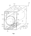
- FIG. 1 shows a housing 10 containing leak-tightness components to be tested 11.
- These components include, for example, a tub 110, which is connected via a Ein Albanyrohr 111 with a Ein Hamptonkasten 112, which in turn is connected to a water inlet 113. Further, the components include a tub vent pipe 114 connecting the tub 110 to the dispenser 112, and a water drain 115 having a drain 116 at the top and connected to a drain pump 117 at the bottom.
- the lye container 110 is a sensor 118 for the level control and a radiator seal 119, the tightness is also checked. All parts 110 to 119 form components 11, which are to be subjected to the leak test.
- These components are contained in the inner space 12 of the housing 10, which contains an atmosphere corresponding to the ambient air.
- the housing 10 surrounds the interior 12 from all sides, but an absolute gas seal of the interior is not required. It is important that the interior contains a gas volume which is delimited from the environment of the housing 10, so that an indicator substance located in the
- the sensor 13 To detect the indicator is a sensor 13 which is connected via a line 14 to the interior 12.
- the sensor 13 includes a suction pump (not shown) that draws gas from the housing 10 and discharges it to the ambient atmosphere.
- the sensor is for example of the HLD5000 type from INFICON GmbH. This is an infrared cuvette.
- the leak test should show whether small amounts of water in the form of droplets escape from the components 11.
- a measurement of the humidity in the housing 10 would not be sufficiently sensitive or would take too long time.
- an indicator is supplied to the water, such as alcohol or the like.
- Drops 15 that drip down through a water leak 16 of the component 11 fall to the bottom 17 and burst there.
- a 0.1 ml drop of a 10% ethanol-water mixture in a volume of washing machine size can be detected within three minutes with the HLD5000 device.
- Advantageous is a convection of the atmosphere in the interior 12 by a blower or by a drive of the washing machine drum (not shown).
- FIGS. 2 and 3 show a device for carrying out the second variant of the method.
- This device consists of a container 20, a carrier film 21 and an arranged above it, consisting of a further film wall 22, which is permeable to contact with water. Between the carrier film 21 and the wall 22 are cavities 23 which are filled with an indicator.
- the wall 22 is connected to the carrier foil 21 either at isolated spot welds 24 or by line-shaped welds. In the case of spot welds creates a uniform gap and in the case of linear welds arise separate foil pockets.
- PVOH polyvinyl alcohol films
- PVAL polyvinyl alcohol films
- Such films are water-soluble. They are under the brand names SOLUBLON or SOKUFOL commercially available. PVOH films are gas-tight against many gases and mechanically relatively robust. They are not hygroscopic but equilibrate with the ambient humidity, ie they absorb moisture and release it again. With commercially available vacuum sealers, they are easy to weld.
- various gases in particular noble gases, can be used, but also CO 2 .
- Trained as a film pocket flexible container 20 forms a water-soluble gas storage, which is spread on the bottom of the housing. As soon as a drop hits the wall 22, it becomes permeable to the indicator, so that the indicator escapes into the atmosphere of the interior of the housing.
- the sensor detects the presence of the indicator in the interior.
- FIG. 4 shows a device 30 for carrying out the third variant of the method.
- This device has a substrate 31 made of a carrier film.
- the substrate 31 carries a coating 32 with a generator material which releases a gaseous indicator 33 upon contact with water.
- the sheet-like device 30 is placed on the bottom of the housing. When a drop falls on the device 30, the generator material 32 generates the indicator 33, which is detected by the sensor connected to the housing.
- the generation of the indicator gas is carried out by chemical reaction.
- the generator substance consists of sodium bicarbonate 2 NaHCO 3 , + C 4 H 6 O 6 .
- Addition of water gives the following reaction: 2 NaHCO 3 + C 4 H 6 O 6 ⁇ C 4 H 4 O 6 Na 2 + 2 H 2 O + 2 CO 2
- potassium bicarbonate sodium carbonate, potassium carbonate or calcium carbonate instead of sodium bicarbonate.
- tartaric acid other acids or acidic substances can be used.
Landscapes
- Physics & Mathematics (AREA)
- General Physics & Mathematics (AREA)
- Investigating Or Analyzing Non-Biological Materials By The Use Of Chemical Means (AREA)
- Examining Or Testing Airtightness (AREA)
- Investigating Or Analysing Materials By The Use Of Chemical Reactions (AREA)
Description
Die Erfindung betrifft ein Verfahren zur Dichtheitsprüfung von wasserführenden Komponenten in einem Gehäuse.The invention relates to a method for leak testing of water-bearing components in a housing.
Bei der Qualitätsprüfung von Massenprodukten ist es häufig erforderlich, eine Dichtheitsprüfung vorzunehmen. So müssen Waschmaschinen und Geschirrspülmaschinen getestet werden, um etwaige Lecks an Schlauchleitungen und Rohrleitungen zu erkennen.In the quality testing of mass products, it is often necessary to perform a leak test. So washing machines and dishwashers must be tested to detect any leaks on hoses and piping.
In
Der Erfindung liegt die Aufgabe zugrunde, ein Verfahren zur Dichtheitsprüfung anzugeben, das für die Dichtheitsprüfung von Komponenten in einem umschließenden Gehäuse geeignet ist, welches eine Atmosphäre enthält.The invention has for its object to provide a method for leak testing, which is suitable for the leak test of components in an enclosing housing containing an atmosphere.
Eine erste Variante der Erfindung sieht vor, dass die wasserführenden Komponenten mit einer Kombination aus Wasser und einem Indikator gefüllt werden, wobei im Falle des Austretens von Tropfen der darin enthaltene Indikator in die von dem Gehäuse umschlossene Atmosphäre entweicht und durch einen auf den Indikator ansprechenden Sensor erkannt wird.A first variant of the invention provides that the water-carrying components are filled with a combination of water and an indicator, wherein in the event of leakage of drops of the indicator contained therein escapes into the enclosure of the housing atmosphere and by a responsive to the indicator sensor is recognized.
Der Indikator kann eine mit dem Wasser vermischte Flüssigkeit sein oder ein Gas, das in dem Wasser gelöst ist. Als Indikator eignen sich in besonderer Weise Alkohole, wie Ethanol, und andere Flüssigkeiten, die schnell in die Atmosphäre hinein verdampfen. Da ein auf den Boden auftreffender Wassertropfen eine große Oberfläche hat, verdampft in kurzer Zeit eine große Menge des Indikators in die im Gehäuse befindliche Atmosphäre. Ein entsprechender Sensor, nämlich ein Gas- oder Dampfsensor, der für den Indikator selektiv empfindlich ist, erkennt das Auftreten des Indikators in der Atmosphäre und signalisiert "Undichtheit". Ein solcher Sensor enthält eine Pumpe, mit der die Gehäuseatmosphäre angesaugt wird. Die Gehäuseatmosphäre wird einem Sensor zugeführt, der Aufschluss über das Vorhandensein des Indikators liefert. Der Sensor kann ein Gas-Sensor auf der Basis der Messung der Infrarotabsorption sein, ein Massenspektrometer oder dergleichen. Ein Vorteil der Erfindung besteht darin, dass die Dichtheitsprüfung keinen Druckaufbau in den zu prüfenden Komponenten erfordert. Die Messung kann vielmehr drucklos durchgeführt werden. Es ist auch möglich, dass der Indikator ein im Wasser in gelöster Form enthaltenes Gas ist, wie beispielsweise CO2 oder Helium.The indicator may be a liquid mixed with the water or a gas dissolved in the water. Alcohols, such as ethanol, and other liquids that evaporate quickly into the atmosphere are particularly suitable as an indicator. Since a drop of water striking the ground has a large surface area, a large amount of the indicator evaporates into the atmosphere in the enclosure in a short time. A corresponding sensor, namely a gas or vapor sensor, which is selectively sensitive to the indicator, detects the presence of the indicator in the atmosphere and signals "leakage". Such a sensor contains a pump with which the housing atmosphere is sucked. The housing atmosphere is fed to a sensor that provides information about the presence of the indicator. The sensor may be a gas sensor based on infrared absorption measurement, a mass spectrometer, or the like. An advantage of the invention is that the leak test requires no pressure build-up in the components to be tested. The measurement can be carried out without pressure become. It is also possible that the indicator is a gas contained in the water in dissolved form, such as CO 2 or helium.
Eine zweite Variante des erfindungsgemäßen Verfahrens sieht vor, dass ein Indikator in ein Behältnis eingegeben wird, das mindestens eine bei Kontakt mit Wasser durchlässig werdende Wand aufweist, dass das Behältnis in dem Gehäuse unterhalb der zu prüfenden Komponenten positioniert wird und dass das Austreten des Indikators aus dem Behältnis durch einen auf den Indikator ansprechenden Sensor erkannt wird. Hierbei wird der Effekt ausgenutzt, dass die Wand des Behältnisses beim Auftreffen eines Wassertropfens für den Indikator durchlässig wird, so dass der Indikator aus dem Behälterinnern in die umgebende Atmosphäre des Gehäuses entweicht. Der Indikator ist vorzugsweise gasförmig oder dampfförmig. Als Indikatorgase eignen sich besonders Edelgase, insbesondere Helium, aber auch CO2.A second variant of the method according to the invention provides that an indicator is entered into a container which has at least one wall permeable to contact with water, that the container is positioned in the housing below the components to be tested and that the emergence of the indicator the container is detected by a responsive to the indicator sensor. In this case, the effect is exploited that the wall of the container is permeable upon impact of a drop of water for the indicator, so that the indicator escapes from the container interior into the surrounding atmosphere of the housing. The indicator is preferably gaseous or vaporous. As indicator gases are particularly noble gases, especially helium, but also CO 2 .
Eine spezielle Ausführungsform der zweiten Variante sieht vor, dass das Behältnis aus Mikrokapseln entsteht, die mit einem Indikator gefüllt sind, der beispielsweise aus Alkohol besteht. Im Falle einer Undichtigkeit gelangt Wasser in Kontakt mit den Mikrokapseln, die dadurch zerstört werden. Der in den Mikrokapseln enthaltene Alkohol wird freigesetzt. Durch einen entsprechenden Sensor wird die Anwesenheit von Alkohol in der Luft erkannt und angezeigt. Die zum Auslösen der Sensorerkennung benötigte Wassermenge ist sehr gering. Sie liegt in der Größenordnung von 0,1 ml. Unter "Mikrokapsel" wird ein Gebilde verstanden, das einen Kern aufweist, der vollständig von einer - gegebenenfalls semipermeablen - dünnen Wand umgeben ist. Die Größe der Mikrokapseln beträgt im Allgemeinen 1-1500 µm (Mikrometer), vorzugsweise 10 µm - 300 µm, nochmals bevorzugt 30 µm - 150 µm, kann aber in Einzelfällen auch mehr, z. B. bis 2000, 3000, 4000, 5000 µm, betragen.A special embodiment of the second variant provides that the container is formed from microcapsules which are filled with an indicator, which consists for example of alcohol. In the event of a leak, water comes into contact with the microcapsules, which are thereby destroyed. The alcohol contained in the microcapsules is released. An appropriate sensor detects and indicates the presence of alcohol in the air. The amount of water needed to trigger the sensor detection is very low. It is on the order of 0.1 ml. The term "microcapsule" is understood to mean a structure which has a core that is completely surrounded by a thin-wall, possibly semipermeable. The size of the microcapsules is generally 1-1500 microns (microns), preferably 10 .mu.m - 300 .mu.m, more preferably 30 .mu.m - 150 .mu.m, but in some cases more, z. B. to 2000, 3000, 4000, 5000 microns, amount.
Die Mikrokapseln können zusammen mit anderen Substanzen, wie Füllstoffen, unverkapselten Geruchs-, oder biologischen Wirkstoffen, gegebenenfalls mit anorganischen oder organischen oder auch biologischen Trägern assoziiert oder auch zusammen mit biologischen Materialien vorliegen. Diese können alle mit Wasser, einer wässrigen Lösung oder einer geeigneten organischen Flüssigkeit oder mit deren Mischungen befeuchtet sein.The microcapsules may be used together with other substances, such as fillers, non-encapsulated odor, or biological agents, optionally with inorganic or organic or even biological carriers associated or also present together with biological materials. These may all be wetted with water, an aqueous solution or a suitable organic liquid or with mixtures thereof.
In einer bevorzugten Ausführung besitzen Mikrokapseln semipermeable Wände. Durch diese kann der Wirkstoff aus der Kapsel heraus in das Wasser diffundieren. Hierbei kann das Wasser von außen durch die Kapselwand dringen, den Inhaltsstoff im Kern lösen und dann zusammen mit dem gelösten Inhaltsstoff aus der Kapsel heraus diffundieren.In a preferred embodiment, microcapsules have semipermeable walls. Through this, the active ingredient can diffuse out of the capsule into the water. In this case, the water can penetrate from the outside through the capsule wall, solve the ingredient in the core and then diffuse out of the capsule together with the dissolved ingredient.
Eine dritte Variante des erfindungsgemäßen Verfahrens sieht vor, dass ein Generatorstoff, der bei Kontakt mit Wasser einen gasförmigen oder dampfförmigen Indikator erzeugt, in dem Gehäuse unterhalb der zu prüfenden Komponenten positioniert wird und dass das Auftreten des Indikators durch einen auf den Indikator ansprechenden Sensor erkannt wird. Der Generatorstoff kann in einem wasserlöslichen Behältnis deponiert werden, wodurch er bei Lagerung gegen Luftfeuchte geschützt ist. Erst beim Auftreffen eines Wassertropfens, wodurch die Wand des Behältnisses durchlässig wird, gelangt Wasser an den Generatorstoff und z. B. CO2 wird freigesetzt und kann dann innerhalb des Gehäuses detektiert werden. Als Generatorstoff eignet sich eine Mischung aus Natron und Säure, die bei Kontakt mit Wasser CO2 als Indikator erzeugt. CO2 ist mit Hilfe eines Infrarotsensors gut nachweisbar.A third variant of the method according to the invention provides that a generator substance, which generates a gaseous or vaporous indicator upon contact with water, is positioned in the housing below the components to be tested and that the occurrence of the indicator is detected by a sensor responding to the indicator , The generator material can be deposited in a water-soluble container, whereby it is protected against atmospheric moisture during storage. Only when hitting a drop of water, whereby the wall of the container is permeable, water reaches the generator material and z. B. CO 2 is released and can then be detected within the housing. As a generator material is a mixture of sodium and acid, which generates CO 2 as an indicator when in contact with water. CO 2 is well detectable with the help of an infrared sensor.
Im Folgenden werden Ausführungsbeispiele der Erfindung unter Bezugnahme auf die Zeichnungen näher erläutert.In the following, embodiments of the invention will be explained in more detail with reference to the drawings.
Es zeigen:
- Fig. 1
- die Darstellung eines Gehäuses einer Waschmaschine während der Dichtheitsprüfung nach der ersten Variante der Erfindung,
- Fig. 2
- eine Seitenansicht eines Behältnisses für die Durchführung der zweiten Variante des erfindungsgemäßen Verfahrens,
- Fig. 3
- eine Draufsicht des Behältnisses nach
Figur 2 , wobei zwei alternative Arten der Verschweißung der Folienlagen dargestellt sind und - Fig. 4
- ein Material aus einem Substrat der mit einem Generatorstoff beschichtet ist, zur Durchführung der dritten Variante des erfindungsgemäßen Verfahrens.
- Fig. 1
- the representation of a housing of a washing machine during the leak test according to the first variant of the invention,
- Fig. 2
- a side view of a container for carrying out the second variant of the method according to the invention,
- Fig. 3
- a top view of the container after
FIG. 2 , wherein two alternative ways of welding the film layers are shown and - Fig. 4
- a material of a substrate which is coated with a generator material, for carrying out the third variant of the method according to the invention.
Zur Erkennung des Indikators dient ein Sensor 13, der über eine Leitung 14 mit dem Innenraum 12 verbunden ist. Der Sensor 13 enthält eine (nicht dargestellte) Saugpumpe, die Gas aus dem Gehäuse 10 absaugt und in die Umgebungsatmosphäre entlässt. Der Sensor ist beispielsweise vom Typ HLD5000 der Firma INFICON GmbH. Hierbei handelt es sich um eine Infrarot-Küvette.To detect the indicator is a
Die Dichtheitsprüfung soll ergeben, ob kleine Wassermengen in Form von Tropfen aus den Komponenten 11 austreten. Eine Messung der Luftfeuchte im Gehäuse 10 wäre nicht genügend empfindlich oder würde zu lange Zeit in Anspruch nehmen. Erfindungsgemäß wird dem Wasser ein Indikator zugeführt, wie Alkohol oder ähnliches. Tropfen 15, die durch ein Wasserleck 16 der Komponente 11 herabtropfen, fallen auf den Boden 17 und zerplatzen dort. Ein 0,1 ml großer Tropfen einer 10%-igen Ethanol-Wasser-Mischung in einem Volumen von Waschmaschinengröße kann innerhalb von drei Minuten mit dem Gerät HLD5000 detektiert werden. Vorteilhaft ist eine Konvektion der Atmosphäre in dem Innenraum 12 durch ein Gebläse oder durch einen Antrieb der (nicht dargestellten) Waschmaschinentrommel.The leak test should show whether small amounts of water in the form of droplets escape from the
Die
Als Material der Wand 22 eignen sich Polyvinylalkohol-Folien (PVOH, auch: PVAL). Solche Folien sind wasserlöslich. Sie sind unter den Markennamen SOLUBLON oder SOKUFOL im Handel erhältlich. PVOH-Folien sind gasdicht gegen viele Gase und mechanisch relativ robust. Sie sind nicht hygroskopisch sondern setzen sich mit der Umgebungsfeuchte ins Gleichgewicht, d. h. sie nehmen Feuchte auf und geben sie auch wieder ab. Mit handelsüblichen Folienschweißgeräten sind sie gut verschweißbar.As the material of the
Als Indikator im Innern des Behältnisses 20 können verschiedene Gase, insbesondere Edelgase, benutzt werden, aber auch CO2.As an indicator in the interior of the
Das als Folientasche ausgebildete flexible Behältnis 20 bildet einen wasserlöslichen Gasspeicher, der auf dem Boden des Gehäuses ausgebreitet wird. Sobald ein Tropfen auf die Wand 22 trifft, wird diese für den Indikator durchlässig, so dass der Indikator in die Atmosphäre des Innenraums des Gehäuses entweicht. Durch den Sensor wird das Vorhandensein des Indikators in dem Innenraum festgestellt.Trained as a film pocket
Die Erzeugung des Indikatorgases erfolgt durch chemische Reaktion. Beispielsweise besteht der Generatorstoff aus Natronweinsäurepulver 2 NaHCO3,+C4H6O6. Bei Zugabe von Wasser ergibt sich folgende Reaktion:
2 NaHCO3 + C4H6O6 → C4H4O6Na2 + 2 H2O + 2 CO2
The generation of the indicator gas is carried out by chemical reaction. For example, the generator substance consists of sodium bicarbonate 2 NaHCO 3 , + C 4 H 6 O 6 . Addition of water gives the following reaction:
2 NaHCO 3 + C 4 H 6 O 6 → C 4 H 4 O 6 Na 2 + 2 H 2 O + 2 CO 2
Dabei entsteht das Indikatorgas CO2, das mit geeigneten Sensoren detektierbar ist.This produces the indicator gas CO 2 , which can be detected with suitable sensors.
Möglich wäre auch der Einsatz von Kaliumhydrogencarbonat, Natriumcarbonat, Kaliumcarbonat oder Calciumcarbonat anstelle von Natriumhydrogencarbonat. Anstelle der Weinsäure können auch andere Säuren oder säurehaltige Substanzen benutzt werden.It would also be possible to use potassium bicarbonate, sodium carbonate, potassium carbonate or calcium carbonate instead of sodium bicarbonate. Instead of tartaric acid, other acids or acidic substances can be used.
Claims (16)
- A method of testing the tightness of water conducting components (11) in a housing (10),
characterized in that
the components (11) are filled with a combination of water and an indicator, wherein in the event of a leakage of drops the indicator contained therein escapes into the atmosphere enclosed by the housing (10) and is detected by a sensor (13) sensitive to the indicator. - A method of testing the tightness of water conducting components (11) in a housing (10),
characterized in that
an indicator is introduced into a container (20) comprising at least one wall (22) which upon contact with water becomes permeable to the indicator, the container (20) is positioned in the housing (10) below the components (11) under test, and the escaping of the indicator from the container is detected by a sensor (13) sensitive to the indicator. - A method of testing the tightness of water conducting components (11) in a housing (10),
characterized in that
a generator substance (32), which upon contact with water produces a gaseous or vaporous indicator, is positioned in the housing (10) below the components (11) under test, and the occurrence of the indicator is detected by a sensor (13) sensitive to the indicator. - The method of claim 1, characterized in that the indicator used is a gas dissolved in the water.
- The method of claim 1 or 2, characterized in that the indicator used is alcohol.
- The method of claim 1 or 2, characterized in that the indicator used is an inert gas, in particular helium.
- The method of claim 1 or 2, characterized in that the indicator used is CO2.
- The method of one of claims 2 to 5, characterized in that the container is formed by a carrier with a coating of microcapsules which allow the substance enclosed in the capsules to escape upon contact with water.
- The method of claim 3, characterized in that the generator substance (32) is provided on a substrate.
- The method of claim 3, characterized in that the generator substance is contained in a container that comprises at least one wall that becomes permeable to the generator substance upon contact with water.
- The method of claim 3, characterized in that the generator substance (32) used is a mixture of sodium and acid, which produces CO2 as the indicator upon contact with water.
- The method of one of the preceding claims, characterized in that the sensor used is a gas sensor with an IR section, into which sensor the atmosphere in the interior of the housing (10) is drawn.
- The method of one of claims 2 to 12, characterized by its use in testing household appliances, such as washing machines or dish washing machines.
- A container (30) comprising a carrier (21) with a coating applied on the carrier (21), the coating being an indicator activated upon contact with water or when water falls on the container (20, 30), for carrying out the method of one of claims 2 to 13.
- The container of claim 14, characterized in that the coating consists of microcapsules which allow the substance enclosed in the capsules to escape upon contact with water.
- The container of claim 14, characterized in that the carrier (21) is made from a flat material such as film or paper.
Applications Claiming Priority (3)
| Application Number | Priority Date | Filing Date | Title |
|---|---|---|---|
| DE102009056172 | 2009-11-27 | ||
| DE102010005494A DE102010005494A1 (en) | 2009-11-27 | 2010-01-23 | Method for testing the density of water-carrying components in a housing |
| PCT/EP2010/066403 WO2011064067A1 (en) | 2009-11-27 | 2010-10-28 | Method for testing the tightness of water conducting components in a housing |
Publications (2)
| Publication Number | Publication Date |
|---|---|
| EP2504680A1 EP2504680A1 (en) | 2012-10-03 |
| EP2504680B1 true EP2504680B1 (en) | 2013-12-11 |
Family
ID=43927235
Family Applications (1)
| Application Number | Title | Priority Date | Filing Date |
|---|---|---|---|
| EP10776972.1A Active EP2504680B1 (en) | 2009-11-27 | 2010-10-28 | Method for testing the tightness of water conducting components in a housing |
Country Status (9)
| Country | Link |
|---|---|
| US (1) | US9188501B2 (en) |
| EP (1) | EP2504680B1 (en) |
| JP (1) | JP2013512418A (en) |
| KR (1) | KR20120116949A (en) |
| CN (1) | CN102639982A (en) |
| BR (1) | BR112012012792B1 (en) |
| DE (1) | DE102010005494A1 (en) |
| RU (1) | RU2012126315A (en) |
| WO (1) | WO2011064067A1 (en) |
Families Citing this family (9)
| Publication number | Priority date | Publication date | Assignee | Title |
|---|---|---|---|---|
| DE102010035432A1 (en) | 2010-08-26 | 2012-03-01 | Inficon Gmbh | Method for leak testing |
| DE102011106165B4 (en) | 2011-06-30 | 2015-07-02 | Sartorius Stedim Biotech Gmbh | Bioreactor container test method and apparatus and use |
| KR102211898B1 (en) * | 2014-11-27 | 2021-02-05 | 삼성전자주식회사 | Apparatus and method for liquid leakage sensing of lithography apparatus |
| DE102016209368B4 (en) * | 2016-05-31 | 2020-03-26 | BSH Hausgeräte GmbH | Method for checking the tightness of an inner container of a household dishwasher |
| JP6708191B2 (en) * | 2017-09-21 | 2020-06-10 | 株式会社デンソー | Leak inspection device and leak inspection method |
| JP6900343B2 (en) * | 2018-04-12 | 2021-07-07 | 日立グローバルライフソリューションズ株式会社 | Water leak inspection system and water leak inspection method |
| DE102020000907A1 (en) | 2020-02-13 | 2021-08-19 | Daimler Ag | Detection of a leak in a cooling circuit |
| US11788918B2 (en) | 2020-06-18 | 2023-10-17 | Trevillyan Labs, Llc | Fluid detection fabric |
| JP7477814B2 (en) | 2022-01-12 | 2024-05-02 | 株式会社 マルナカ | Leak inspection device and leak inspection method |
Family Cites Families (83)
| Publication number | Priority date | Publication date | Assignee | Title |
|---|---|---|---|---|
| US2759175A (en) * | 1954-03-12 | 1956-08-14 | Thomas R Spalding | Leak detector for pipe joint |
| US3173477A (en) * | 1963-04-17 | 1965-03-16 | Gen Electric | Leak detector for heat exchangers in gas insulated electric apparatus |
| US3712327A (en) * | 1971-03-23 | 1973-01-23 | S Pagenkopf | Automatic leak detection and shutoff system |
| US3770002A (en) * | 1971-11-01 | 1973-11-06 | L Brown | Automatic water shut-off system |
| US3894138A (en) * | 1971-11-05 | 1975-07-08 | Kraftwerk Union Ag | Apparatus for measuring coolant leakage in electrical power generating machines |
| GB1472445A (en) * | 1973-08-23 | 1977-05-04 | Electricite De France | Leak detection in heat-exchangers |
| US3874403A (en) * | 1973-11-14 | 1975-04-01 | Wayne L Fischer | Safety attachment for appliances subject to fluid leakage |
| DE2635829B2 (en) * | 1976-08-09 | 1978-08-03 | Kraftwerk Union Ag, 4330 Muelheim | Method for the determination of cooling water leaks in at least in the stator water-cooled windings of electrical machines as well as device for carrying out the method |
| US4138856A (en) * | 1977-10-07 | 1979-02-13 | Sun-Econ, Inc. | Leak detector device |
| US4186215A (en) * | 1978-03-02 | 1980-01-29 | Pepsico. Inc. | Beverage carbonation arrangement |
| CH626974A5 (en) * | 1978-03-21 | 1981-12-15 | Bbc Brown Boveri & Cie | |
| FR2506509A1 (en) * | 1981-05-20 | 1982-11-26 | Labo Electronique Physique | HOUSEHOLD WASHING MACHINE OR DISHWASHER APPLIANCE WITH ALARM DEVICE IN THE EVENT OF OVERFLOW OR LEAKAGE OF WATER |
| US4524607A (en) * | 1982-04-05 | 1985-06-25 | Science Applications International Corporation | System and method for locating leaking tubes |
| DE3305005C2 (en) * | 1983-02-14 | 1985-02-14 | Wolfgang Dipl.-Phys. Dr.-Ing. 7500 Karlsruhe Issel | Method and device for determining the temperature distribution along a route |
| JPS60257337A (en) * | 1984-06-04 | 1985-12-19 | Toshiba Corp | Water leakage detecting agent and water leakage detecting method |
| US4669791A (en) * | 1984-09-06 | 1987-06-02 | Integrated Circuit Systems, Ltd. | Connector apparatus |
| FR2574545B1 (en) * | 1984-12-06 | 1987-02-13 | Electricite De France | METHOD FOR DETECTING LEAKS IN AN OPERATING HEAT EXCHANGER |
| EP0365042A1 (en) * | 1987-03-31 | 1990-04-25 | FINN-AQUA SANTASALO-SOHLBERG GmbH | Method for monitoring leakage in liquid conduit systems of cold drying equipment and adapted cold drying equipment for carrying out this method |
| US4789853A (en) * | 1987-06-15 | 1988-12-06 | Gentiluomo Joseph A | Detection device for electrically conductive fluids |
| US5046353A (en) * | 1989-01-26 | 1991-09-10 | Tracer Research Corporation | Underground pipe leak detection system |
| US5070723A (en) * | 1989-09-20 | 1991-12-10 | Electric Power Research Institute, Inc. | Condenser on-line leak detector and method |
| CA1330516C (en) * | 1989-09-26 | 1994-07-05 | Leslie Ronald Quaife | Test-fluid composition and method for detecting leaks in pipelines and associated facilities |
| US5163315A (en) * | 1990-07-10 | 1992-11-17 | Daikin Industries, Ltd. | Leak detecting method for vessels |
| JPH04142434A (en) * | 1990-10-04 | 1992-05-15 | Toshiba Corp | Leakage monitoring method |
| JPH055670A (en) * | 1991-06-27 | 1993-01-14 | Toshiba Corp | Detection of leak of high temperature water |
| DE4125373A1 (en) * | 1991-07-31 | 1993-02-04 | Siemens Ag | SENSOR HOSE FOR MONITORING A MEDIUM |
| US5229750A (en) * | 1991-08-02 | 1993-07-20 | Welch Jr James G | Fail-safe leak detector including independent and repetetive sensing means |
| US5883300A (en) * | 1996-01-03 | 1999-03-16 | Johnson; Addison | System and method for containing fluid leaks and overflows from appliances |
| JPH1026574A (en) * | 1996-07-12 | 1998-01-27 | Nippon Taanaa Kk | Leak detecting implement for liquid substance and liquid substance-filled multilayer bag body with the detecting implement built in as well as waterbed |
| US6170320B1 (en) * | 1997-01-24 | 2001-01-09 | Mainstream Engineering Corporation | Method of introducing an additive into a fluid system, especially useful for leak detection, as well as an apparatus for leak detection and a composition useful for leak detection |
| JPH10227712A (en) * | 1997-02-18 | 1998-08-25 | Japan Atom Energy Res Inst | Method for searching leaking part of pipe and vacuum device |
| US5835976A (en) * | 1997-06-19 | 1998-11-10 | General Motors Corporation | Non pressurized method for heat exchanger internal leak detection |
| US5992218A (en) * | 1997-08-25 | 1999-11-30 | Tryba; Stephen A. | Water leakage protector apparatus |
| US6526807B1 (en) * | 1998-06-18 | 2003-03-04 | Joseph Doumit | Early warning water leak detection system |
| US6147613A (en) * | 1998-06-18 | 2000-11-14 | Doumit; Joseph | Early warning water leak detection system |
| US6227036B1 (en) * | 1998-10-28 | 2001-05-08 | The Regents Of The University Of Michigan | Multiple microphone photoacoustic leak detection and localization system and method |
| US6063632A (en) * | 1998-11-12 | 2000-05-16 | Perkins; Gary | Water leak detection |
| FR2786566B1 (en) * | 1998-11-26 | 2000-12-29 | Cit Alcatel | METHOD AND DEVICE FOR DETECTING LEAKS ON AUTOMOTIVE EXCHANGERS |
| US6229229B1 (en) * | 1999-05-24 | 2001-05-08 | Terry D. Sharp | Liquid sensor for disabling an electrical device |
| DE19924560C1 (en) * | 1999-05-28 | 2000-12-21 | Siemens Ag | Pipeline leak detection and location, comprises use of electrically-pulsed parallel wire and permeable collection line with carrier flow, to detect bursts of electrolytically-released substance |
| US6629043B1 (en) * | 1999-09-30 | 2003-09-30 | Jere Poteat | Multiple port leak detection system |
| GB9929062D0 (en) * | 1999-12-08 | 2000-02-02 | Werner Thomas | Heat exchangers |
| US6460405B1 (en) * | 2000-10-02 | 2002-10-08 | Mocon, Inc. | Method for measuring gas leakage from sealed packages |
| US6690281B2 (en) * | 2000-12-18 | 2004-02-10 | Joseph A. Palmer | Water detector and alarm |
| US6450012B1 (en) * | 2001-04-30 | 2002-09-17 | Mocon, Inc. | Multi-port gas leakage measurement fixture |
| US6489895B1 (en) * | 2001-10-15 | 2002-12-03 | Steven P. Apelman | Fail-safe leak detection and flood prevention apparatus |
| SE0200399D0 (en) * | 2002-02-12 | 2002-02-12 | Timo Siikaluoma | Method for fluid indication |
| JP3698108B2 (en) * | 2002-02-20 | 2005-09-21 | 株式会社デンソー | Airtight leak inspection method and apparatus |
| US6742384B2 (en) * | 2002-07-02 | 2004-06-01 | Carrier Corporation | Trace gas management system for leak detection operations |
| US7084777B2 (en) * | 2002-09-05 | 2006-08-01 | Ninberg Jeffrey A | Fluid leak detection device |
| US6639517B1 (en) * | 2002-09-30 | 2003-10-28 | James Chapman | Leak detection mat and system |
| AU2003286587B2 (en) * | 2002-10-24 | 2009-04-23 | Clean Air Filter | Method and apparatus for leak testing an environmental enclosure |
| US20040126888A1 (en) * | 2002-12-16 | 2004-07-01 | Puri Pushpinder Singh | Double walled vessels for odorant containments |
| US20040115818A1 (en) * | 2002-12-16 | 2004-06-17 | Puri Pushpinder Singh | Leak detection by reactions at the leak site |
| US20050287276A1 (en) * | 2003-01-22 | 2005-12-29 | Durafizz, Llc | Microencapsulation for sustained delivery of carbon dioxide |
| US7158039B2 (en) * | 2003-03-26 | 2007-01-02 | Tsuden Kabushiki Kaisha | Liquid leakage sensor and liquid leakage detecting system |
| US6941829B1 (en) * | 2003-07-30 | 2005-09-13 | Scott J. Long | Leak detector |
| US6873263B1 (en) * | 2003-08-25 | 2005-03-29 | Leonard M. Hohman | Water leak detection |
| JP2005146549A (en) * | 2003-11-12 | 2005-06-09 | Mym Corp | Leakage detector in washing/dressing table and sink |
| US6792967B1 (en) * | 2003-11-13 | 2004-09-21 | Robert C. Franklin | Shutoff valve system with leak detector |
| WO2005054806A1 (en) * | 2003-12-05 | 2005-06-16 | Sensistor Technologies Ab | System and method for determining the leakproofness of an object |
| GB2409724A (en) * | 2003-12-30 | 2005-07-06 | Adphil Ltd | NMR Leak Test |
| US8333108B2 (en) * | 2004-06-30 | 2012-12-18 | Valeo, Inc. | Detection system for localizing defective seals in heat exchangers |
| DE102004045803A1 (en) * | 2004-09-22 | 2006-04-06 | Inficon Gmbh | Leak test method and leak tester |
| US7423542B1 (en) * | 2005-03-11 | 2008-09-09 | Spectrapure, Inc. | Water detection sensing system |
| US7253741B2 (en) * | 2005-03-14 | 2007-08-07 | Fiorletta Carl A | Automated system to monitor multiple sources of water leaks in residential and commercial buildings |
| US20060244616A1 (en) * | 2005-04-01 | 2006-11-02 | Clyde Hill | Moisture sensing strips |
| US7082959B1 (en) * | 2006-03-21 | 2006-08-01 | Franklin Robert C | Shutoff valve system with leak detector |
| DE102006017958A1 (en) * | 2006-04-13 | 2007-10-25 | Volker Dahm | Method and device for determining the tightness of a test object |
| US20080055112A1 (en) * | 2006-08-31 | 2008-03-06 | Mcginty Joseph Ralph | Water detection unit and system |
| US7489253B2 (en) * | 2006-09-07 | 2009-02-10 | Kevin M. Murphy, Llc | Fluid detection and containment apparatus |
| KR20090073240A (en) * | 2006-10-25 | 2009-07-02 | 캐논 가부시끼가이샤 | Inflammable substance sensor and fuel cell including the same |
| DE102007032250B3 (en) | 2007-07-11 | 2008-12-18 | ROWO Coating Gesellschaft für Beschichtung mbH | Liquid i.e. water, leakage detecting device i.e. humidity sensor, for e.g. washing machine, has conductor paths present on side of surface unit, where one side of surface unit is flat while another side of surface unit is rough |
| US7696889B2 (en) * | 2007-10-09 | 2010-04-13 | David Woodrow J | Fluid leak detection system and associated method |
| WO2009051530A1 (en) * | 2007-10-15 | 2009-04-23 | Adixen Sensistor Ab | Leak detection system comprising a tracer gas mediating unit. |
| US20090126465A1 (en) * | 2007-11-16 | 2009-05-21 | Electrolux Home Products, Inc. | Leak detection system for a dishwasher and associated method |
| US7671754B2 (en) * | 2007-11-30 | 2010-03-02 | Amtrol Licensing Inc. | Sensor for detecting leakage of a liquid |
| US7631666B1 (en) * | 2008-08-04 | 2009-12-15 | Kwan Yuen Abraham Ng | Reinforced flexible hose with leakage indicator and method of making same |
| US20100073162A1 (en) * | 2008-09-05 | 2010-03-25 | Michael David Johnson | Hand washing reminder device and method |
| FR2935800B1 (en) * | 2008-09-09 | 2010-11-19 | R & I Alliance | METHOD AND DEVICE FOR DETECTING LEAKS IN A UNDERGROUND LIQUID CONDUIT, IN PARTICULAR A WATER CONDUIT |
| US7926504B2 (en) * | 2009-01-21 | 2011-04-19 | Sharp Technologies, Inc. | Method and systems for detecting and preventing leakage |
| US8457908B2 (en) * | 2009-06-11 | 2013-06-04 | University Of Washington | Sensing events affecting liquid flow in a liquid distribution system |
| DE102010035432A1 (en) * | 2010-08-26 | 2012-03-01 | Inficon Gmbh | Method for leak testing |
-
2010
- 2010-01-23 DE DE102010005494A patent/DE102010005494A1/en not_active Withdrawn
- 2010-10-28 BR BR112012012792-6A patent/BR112012012792B1/en active IP Right Grant
- 2010-10-28 EP EP10776972.1A patent/EP2504680B1/en active Active
- 2010-10-28 RU RU2012126315/28A patent/RU2012126315A/en unknown
- 2010-10-28 US US13/511,866 patent/US9188501B2/en active Active
- 2010-10-28 JP JP2012540346A patent/JP2013512418A/en active Pending
- 2010-10-28 WO PCT/EP2010/066403 patent/WO2011064067A1/en active Application Filing
- 2010-10-28 KR KR1020127016765A patent/KR20120116949A/en not_active Application Discontinuation
- 2010-10-28 CN CN2010800533203A patent/CN102639982A/en active Pending
Also Published As
| Publication number | Publication date |
|---|---|
| BR112012012792B1 (en) | 2020-11-17 |
| KR20120116949A (en) | 2012-10-23 |
| EP2504680A1 (en) | 2012-10-03 |
| RU2012126315A (en) | 2014-01-10 |
| BR112012012792A2 (en) | 2016-08-16 |
| US9188501B2 (en) | 2015-11-17 |
| US20120270324A1 (en) | 2012-10-25 |
| JP2013512418A (en) | 2013-04-11 |
| CN102639982A (en) | 2012-08-15 |
| DE102010005494A1 (en) | 2011-06-01 |
| WO2011064067A1 (en) | 2011-06-03 |
Similar Documents
| Publication | Publication Date | Title |
|---|---|---|
| EP2504680B1 (en) | Method for testing the tightness of water conducting components in a housing | |
| DE102011086486B4 (en) | Device and method for rapid leak detection on dimensionally stable/slack packaging without the addition of tracer gas | |
| EP3227655B1 (en) | Leak-tightness test with carrier gas in foil chamber | |
| DE10012446B4 (en) | Method for measuring the gas permeability of a coating on a plastic wall and apparatus for carrying out the method | |
| DE202019005500U1 (en) | Device for leak testing a liquid-filled test object | |
| WO2016177478A1 (en) | Method and apparatus for an integrity test of a test container | |
| DE4205894A1 (en) | DEVICE FOR DETECTING AND / OR MEASURING OR CONTROLLING THE TEXTURE, ESPECIALLY CHEMICAL AND / OR BIOLOGICAL RELATIONSHIPS WITH THE HELP OF AT LEAST ONE INDICATOR IN LIQUID MILIEU, ESPECIALLY AQUEOUS MILIEU, AND LIKE | |
| EP2135046A1 (en) | Container unit for storing and protecting laboratory substances | |
| EP2929313B1 (en) | Apparatus and method for determining the average layer thickness and the permeation rate of a packaging material | |
| WO2012025500A1 (en) | Method for testing leak tightness | |
| KR101199868B1 (en) | pH-sensitive coating material and spray can paint using the same | |
| EP3894821B1 (en) | Leak test of a liquid-filled test specimen | |
| DE1473704A1 (en) | Procedure for serial testing of small containers for leaks | |
| DE3741664C1 (en) | Colorimetric test tube | |
| DE102016118701B4 (en) | Method of testing a pressurized liquid for dissolved and/or entrained gases | |
| DE102015003745B4 (en) | Mobile testing device, gas meter and system for testing a gas meter | |
| KR100994737B1 (en) | pH-SENSITIVE COATING MATERIAL, METHOD FOR MANUFACTURING THE SAME AND METHOD FOR DETECTING LEAKAGE USING THE SAME | |
| EP1542801A1 (en) | Device for determining and displaying at least one physical, chemical or biological property of a test liquid | |
| DE102020200591B4 (en) | Device and method for the integral detection of a moisture flow | |
| WO2022199917A1 (en) | Functionally testing a leak detection device for checking the sealing tightness of an inspection object filled with a liquid | |
| DE19954581A1 (en) | Non-destructive testing of fabrics and textile laminates | |
| EP3073922B1 (en) | Individually packaged disposable blood testing unit | |
| DE102022117795A1 (en) | Method for determining one or more properties of a gas barrier and a leak monitoring system | |
| DE19749208A1 (en) | Method and device for testing compressed gas cylinders | |
| DE202010001960U1 (en) | Leak test device |
Legal Events
| Date | Code | Title | Description |
|---|---|---|---|
| PUAI | Public reference made under article 153(3) epc to a published international application that has entered the european phase |
Free format text: ORIGINAL CODE: 0009012 |
|
| 17P | Request for examination filed |
Effective date: 20120521 |
|
| AK | Designated contracting states |
Kind code of ref document: A1 Designated state(s): AL AT BE BG CH CY CZ DE DK EE ES FI FR GB GR HR HU IE IS IT LI LT LU LV MC MK MT NL NO PL PT RO RS SE SI SK SM TR |
|
| DAX | Request for extension of the european patent (deleted) | ||
| GRAP | Despatch of communication of intention to grant a patent |
Free format text: ORIGINAL CODE: EPIDOSNIGR1 |
|
| INTG | Intention to grant announced |
Effective date: 20130613 |
|
| GRAS | Grant fee paid |
Free format text: ORIGINAL CODE: EPIDOSNIGR3 |
|
| GRAA | (expected) grant |
Free format text: ORIGINAL CODE: 0009210 |
|
| AK | Designated contracting states |
Kind code of ref document: B1 Designated state(s): AL AT BE BG CH CY CZ DE DK EE ES FI FR GB GR HR HU IE IS IT LI LT LU LV MC MK MT NL NO PL PT RO RS SE SI SK SM TR |
|
| REG | Reference to a national code |
Ref country code: GB Ref legal event code: FG4D Free format text: NOT ENGLISH |
|
| REG | Reference to a national code |
Ref country code: CH Ref legal event code: EP |
|
| REG | Reference to a national code |
Ref country code: AT Ref legal event code: REF Ref document number: 644828 Country of ref document: AT Kind code of ref document: T Effective date: 20140115 |
|
| REG | Reference to a national code |
Ref country code: IE Ref legal event code: FG4D Free format text: LANGUAGE OF EP DOCUMENT: GERMAN |
|
| REG | Reference to a national code |
Ref country code: DE Ref legal event code: R096 Ref document number: 502010005666 Country of ref document: DE Effective date: 20140206 |
|
| REG | Reference to a national code |
Ref country code: NL Ref legal event code: VDEP Effective date: 20131211 |
|
| PG25 | Lapsed in a contracting state [announced via postgrant information from national office to epo] |
Ref country code: SE Free format text: LAPSE BECAUSE OF FAILURE TO SUBMIT A TRANSLATION OF THE DESCRIPTION OR TO PAY THE FEE WITHIN THE PRESCRIBED TIME-LIMIT Effective date: 20131211 Ref country code: HR Free format text: LAPSE BECAUSE OF FAILURE TO SUBMIT A TRANSLATION OF THE DESCRIPTION OR TO PAY THE FEE WITHIN THE PRESCRIBED TIME-LIMIT Effective date: 20131211 Ref country code: NL Free format text: LAPSE BECAUSE OF FAILURE TO SUBMIT A TRANSLATION OF THE DESCRIPTION OR TO PAY THE FEE WITHIN THE PRESCRIBED TIME-LIMIT Effective date: 20131211 Ref country code: FI Free format text: LAPSE BECAUSE OF FAILURE TO SUBMIT A TRANSLATION OF THE DESCRIPTION OR TO PAY THE FEE WITHIN THE PRESCRIBED TIME-LIMIT Effective date: 20131211 Ref country code: LT Free format text: LAPSE BECAUSE OF FAILURE TO SUBMIT A TRANSLATION OF THE DESCRIPTION OR TO PAY THE FEE WITHIN THE PRESCRIBED TIME-LIMIT Effective date: 20131211 Ref country code: NO Free format text: LAPSE BECAUSE OF FAILURE TO SUBMIT A TRANSLATION OF THE DESCRIPTION OR TO PAY THE FEE WITHIN THE PRESCRIBED TIME-LIMIT Effective date: 20140311 |
|
| REG | Reference to a national code |
Ref country code: LT Ref legal event code: MG4D |
|
| PG25 | Lapsed in a contracting state [announced via postgrant information from national office to epo] |
Ref country code: RS Free format text: LAPSE BECAUSE OF FAILURE TO SUBMIT A TRANSLATION OF THE DESCRIPTION OR TO PAY THE FEE WITHIN THE PRESCRIBED TIME-LIMIT Effective date: 20131211 Ref country code: CY Free format text: LAPSE BECAUSE OF FAILURE TO SUBMIT A TRANSLATION OF THE DESCRIPTION OR TO PAY THE FEE WITHIN THE PRESCRIBED TIME-LIMIT Effective date: 20131211 Ref country code: LV Free format text: LAPSE BECAUSE OF FAILURE TO SUBMIT A TRANSLATION OF THE DESCRIPTION OR TO PAY THE FEE WITHIN THE PRESCRIBED TIME-LIMIT Effective date: 20131211 |
|
| PG25 | Lapsed in a contracting state [announced via postgrant information from national office to epo] |
Ref country code: EE Free format text: LAPSE BECAUSE OF FAILURE TO SUBMIT A TRANSLATION OF THE DESCRIPTION OR TO PAY THE FEE WITHIN THE PRESCRIBED TIME-LIMIT Effective date: 20131211 Ref country code: IS Free format text: LAPSE BECAUSE OF FAILURE TO SUBMIT A TRANSLATION OF THE DESCRIPTION OR TO PAY THE FEE WITHIN THE PRESCRIBED TIME-LIMIT Effective date: 20140411 |
|
| PG25 | Lapsed in a contracting state [announced via postgrant information from national office to epo] |
Ref country code: PL Free format text: LAPSE BECAUSE OF FAILURE TO SUBMIT A TRANSLATION OF THE DESCRIPTION OR TO PAY THE FEE WITHIN THE PRESCRIBED TIME-LIMIT Effective date: 20131211 Ref country code: PT Free format text: LAPSE BECAUSE OF FAILURE TO SUBMIT A TRANSLATION OF THE DESCRIPTION OR TO PAY THE FEE WITHIN THE PRESCRIBED TIME-LIMIT Effective date: 20140411 Ref country code: ES Free format text: LAPSE BECAUSE OF FAILURE TO SUBMIT A TRANSLATION OF THE DESCRIPTION OR TO PAY THE FEE WITHIN THE PRESCRIBED TIME-LIMIT Effective date: 20131211 Ref country code: RO Free format text: LAPSE BECAUSE OF FAILURE TO SUBMIT A TRANSLATION OF THE DESCRIPTION OR TO PAY THE FEE WITHIN THE PRESCRIBED TIME-LIMIT Effective date: 20131211 Ref country code: SK Free format text: LAPSE BECAUSE OF FAILURE TO SUBMIT A TRANSLATION OF THE DESCRIPTION OR TO PAY THE FEE WITHIN THE PRESCRIBED TIME-LIMIT Effective date: 20131211 Ref country code: CZ Free format text: LAPSE BECAUSE OF FAILURE TO SUBMIT A TRANSLATION OF THE DESCRIPTION OR TO PAY THE FEE WITHIN THE PRESCRIBED TIME-LIMIT Effective date: 20131211 |
|
| REG | Reference to a national code |
Ref country code: DE Ref legal event code: R097 Ref document number: 502010005666 Country of ref document: DE |
|
| PLBE | No opposition filed within time limit |
Free format text: ORIGINAL CODE: 0009261 |
|
| STAA | Information on the status of an ep patent application or granted ep patent |
Free format text: STATUS: NO OPPOSITION FILED WITHIN TIME LIMIT |
|
| PG25 | Lapsed in a contracting state [announced via postgrant information from national office to epo] |
Ref country code: DK Free format text: LAPSE BECAUSE OF FAILURE TO SUBMIT A TRANSLATION OF THE DESCRIPTION OR TO PAY THE FEE WITHIN THE PRESCRIBED TIME-LIMIT Effective date: 20131211 |
|
| 26N | No opposition filed |
Effective date: 20140912 |
|
| REG | Reference to a national code |
Ref country code: DE Ref legal event code: R097 Ref document number: 502010005666 Country of ref document: DE Effective date: 20140912 |
|
| PG25 | Lapsed in a contracting state [announced via postgrant information from national office to epo] |
Ref country code: SI Free format text: LAPSE BECAUSE OF FAILURE TO SUBMIT A TRANSLATION OF THE DESCRIPTION OR TO PAY THE FEE WITHIN THE PRESCRIBED TIME-LIMIT Effective date: 20131211 |
|
| PG25 | Lapsed in a contracting state [announced via postgrant information from national office to epo] |
Ref country code: MC Free format text: LAPSE BECAUSE OF FAILURE TO SUBMIT A TRANSLATION OF THE DESCRIPTION OR TO PAY THE FEE WITHIN THE PRESCRIBED TIME-LIMIT Effective date: 20131211 Ref country code: LU Free format text: LAPSE BECAUSE OF FAILURE TO SUBMIT A TRANSLATION OF THE DESCRIPTION OR TO PAY THE FEE WITHIN THE PRESCRIBED TIME-LIMIT Effective date: 20141028 |
|
| REG | Reference to a national code |
Ref country code: CH Ref legal event code: PL |
|
| GBPC | Gb: european patent ceased through non-payment of renewal fee |
Effective date: 20141028 |
|
| PG25 | Lapsed in a contracting state [announced via postgrant information from national office to epo] |
Ref country code: BE Free format text: LAPSE BECAUSE OF NON-PAYMENT OF DUE FEES Effective date: 20141031 |
|
| REG | Reference to a national code |
Ref country code: IE Ref legal event code: MM4A |
|
| PG25 | Lapsed in a contracting state [announced via postgrant information from national office to epo] |
Ref country code: CH Free format text: LAPSE BECAUSE OF NON-PAYMENT OF DUE FEES Effective date: 20141031 Ref country code: LI Free format text: LAPSE BECAUSE OF NON-PAYMENT OF DUE FEES Effective date: 20141031 Ref country code: GB Free format text: LAPSE BECAUSE OF NON-PAYMENT OF DUE FEES Effective date: 20141028 |
|
| REG | Reference to a national code |
Ref country code: FR Ref legal event code: PLFP Year of fee payment: 6 |
|
| PG25 | Lapsed in a contracting state [announced via postgrant information from national office to epo] |
Ref country code: IE Free format text: LAPSE BECAUSE OF NON-PAYMENT OF DUE FEES Effective date: 20141028 |
|
| PG25 | Lapsed in a contracting state [announced via postgrant information from national office to epo] |
Ref country code: SM Free format text: LAPSE BECAUSE OF FAILURE TO SUBMIT A TRANSLATION OF THE DESCRIPTION OR TO PAY THE FEE WITHIN THE PRESCRIBED TIME-LIMIT Effective date: 20131211 |
|
| PG25 | Lapsed in a contracting state [announced via postgrant information from national office to epo] |
Ref country code: BG Free format text: LAPSE BECAUSE OF FAILURE TO SUBMIT A TRANSLATION OF THE DESCRIPTION OR TO PAY THE FEE WITHIN THE PRESCRIBED TIME-LIMIT Effective date: 20131211 Ref country code: GR Free format text: LAPSE BECAUSE OF FAILURE TO SUBMIT A TRANSLATION OF THE DESCRIPTION OR TO PAY THE FEE WITHIN THE PRESCRIBED TIME-LIMIT Effective date: 20140312 |
|
| PG25 | Lapsed in a contracting state [announced via postgrant information from national office to epo] |
Ref country code: HU Free format text: LAPSE BECAUSE OF FAILURE TO SUBMIT A TRANSLATION OF THE DESCRIPTION OR TO PAY THE FEE WITHIN THE PRESCRIBED TIME-LIMIT; INVALID AB INITIO Effective date: 20101028 Ref country code: MT Free format text: LAPSE BECAUSE OF FAILURE TO SUBMIT A TRANSLATION OF THE DESCRIPTION OR TO PAY THE FEE WITHIN THE PRESCRIBED TIME-LIMIT Effective date: 20131211 Ref country code: TR Free format text: LAPSE BECAUSE OF FAILURE TO SUBMIT A TRANSLATION OF THE DESCRIPTION OR TO PAY THE FEE WITHIN THE PRESCRIBED TIME-LIMIT Effective date: 20131211 |
|
| REG | Reference to a national code |
Ref country code: FR Ref legal event code: PLFP Year of fee payment: 7 |
|
| REG | Reference to a national code |
Ref country code: AT Ref legal event code: MM01 Ref document number: 644828 Country of ref document: AT Kind code of ref document: T Effective date: 20151028 |
|
| PG25 | Lapsed in a contracting state [announced via postgrant information from national office to epo] |
Ref country code: AT Free format text: LAPSE BECAUSE OF NON-PAYMENT OF DUE FEES Effective date: 20151028 |
|
| REG | Reference to a national code |
Ref country code: FR Ref legal event code: PLFP Year of fee payment: 8 |
|
| PG25 | Lapsed in a contracting state [announced via postgrant information from national office to epo] |
Ref country code: MK Free format text: LAPSE BECAUSE OF FAILURE TO SUBMIT A TRANSLATION OF THE DESCRIPTION OR TO PAY THE FEE WITHIN THE PRESCRIBED TIME-LIMIT Effective date: 20131211 |
|
| REG | Reference to a national code |
Ref country code: FR Ref legal event code: PLFP Year of fee payment: 9 |
|
| PG25 | Lapsed in a contracting state [announced via postgrant information from national office to epo] |
Ref country code: AL Free format text: LAPSE BECAUSE OF FAILURE TO SUBMIT A TRANSLATION OF THE DESCRIPTION OR TO PAY THE FEE WITHIN THE PRESCRIBED TIME-LIMIT Effective date: 20131211 |
|
| P01 | Opt-out of the competence of the unified patent court (upc) registered |
Effective date: 20230420 |
|
| PGFP | Annual fee paid to national office [announced via postgrant information from national office to epo] |
Ref country code: IT Payment date: 20231031 Year of fee payment: 14 Ref country code: FR Payment date: 20231023 Year of fee payment: 14 Ref country code: DE Payment date: 20231026 Year of fee payment: 14 |