EP2504628B1 - Hood unit with lifting/lowering device in the hood - Google Patents
Hood unit with lifting/lowering device in the hood Download PDFInfo
- Publication number
- EP2504628B1 EP2504628B1 EP10784989.5A EP10784989A EP2504628B1 EP 2504628 B1 EP2504628 B1 EP 2504628B1 EP 10784989 A EP10784989 A EP 10784989A EP 2504628 B1 EP2504628 B1 EP 2504628B1
- Authority
- EP
- European Patent Office
- Prior art keywords
- hood
- actual
- hood unit
- unit
- support element
- Prior art date
- Legal status (The legal status is an assumption and is not a legal conclusion. Google has not performed a legal analysis and makes no representation as to the accuracy of the status listed.)
- Active
Links
Images


Classifications
-
- F—MECHANICAL ENGINEERING; LIGHTING; HEATING; WEAPONS; BLASTING
- F24—HEATING; RANGES; VENTILATING
- F24C—DOMESTIC STOVES OR RANGES ; DETAILS OF DOMESTIC STOVES OR RANGES, OF GENERAL APPLICATION
- F24C15/00—Details
- F24C15/20—Removing cooking fumes
- F24C15/2078—Removing cooking fumes movable
- F24C15/2085—Removing cooking fumes movable adjustable in height
-
- F—MECHANICAL ENGINEERING; LIGHTING; HEATING; WEAPONS; BLASTING
- F24—HEATING; RANGES; VENTILATING
- F24C—DOMESTIC STOVES OR RANGES ; DETAILS OF DOMESTIC STOVES OR RANGES, OF GENERAL APPLICATION
- F24C15/00—Details
- F24C15/20—Removing cooking fumes
- F24C15/2064—Removing cooking fumes illumination for cooking hood
Definitions
- the present invention relates to kitchen hood units according to the preamble of claim 1, both of suction type and of filter type.
- So-called "Island” hoods are known for installation in the centre of a room, spaced from the walls, and have a chimney rigid with the actual hood, the upper or other end of the chimney being fixed to the ceiling.
- the chimney can be of telescopic form to be able to adjust within determined limits the distance of the hood unit from the ceiling, in order to adapt it to rooms of different height, so that the hood unit can be disposed at an optimal distance from the cooking hob. It should be noted that the installation of an island hood is fairly complicated and requires the intervention of two persons.
- hood unit types have been marketed requiring a somewhat different installation method from the classic type, these including so-called "chandelier" hoods.
- These are hood units which do not comprise a fume evacuation conduit (so that they only act by filtration) and in which the actual hood is suspended from the ceiling by wires or tubes, as in the case of chandeliers.
- hood units have the advantage of simplified installation in addition to a reduced visual impact.
- these hood units have poor performance.
- ceiling hood units exist, having the advantage of minimum visual impact, they being incorporated into the ceiling, however they present certain disadvantages. In fact, they require the presence of a false ceiling and moreover, even though they can discharge the indrawn fumes outside the room, they have limited performance because the hood unit is excessively spaced from the cooking hob and the fumes can fill the entire room before being drawn in. Moreover, for the same reason, cooking fats being present in the vapours can deposit on furniture and walls before reaching the hood unit.
- the lifting (or raising) /lowering mechanism can be manual (e.g. of the counterweighted type) or motorized.
- a version of the lifting/lowering island hood with counterweight is produced by WESCO, while MIELE produces a motorized version.
- An object of the present invention is to provide a hood unit, the elevation of which can however be varied by the user, so that it also becomes a lifting /lowering hood unit.
- a kitchen hood unit comprising an actual hood and suspension means for suspending it from a support element to be fixed to the ceiling of the room in which the hood unit is located, with the features of claim 1.
- the kitchen hood unit comprises an actual hood overlying a cooking hob, and suspension means having a length which can be varied by the user to cause the actual hood to approach and withdraw from the cooking hob, said suspension means comprising a lifting/lowering device to vary the length of the suspension means with said lifting/lowering device being contained in the actual hood.
- the present hood unit advantageous in that it is very easy to install: Instead of having to install a support element bearing the lifting/lowering device and also carrying the suspension means with the actual hood, all it is necessary is to fix the suspension means to the ceiling via a support element.
- the hood unit according to the invention is also easy to clean and easy to maintain: During the maintenance there is no need to remove the support from the ceiling or to work on a ladder. All the cleaning and maintenance operations can be performed while the hood is in the lower position and can be easily accessed. If there is the need to remove or change the hood, it can be disconnected/dismounted easily and simply changed against a new one.
- this inventive hood unit requires less volume of the transport packaging: By putting the lifting/lowering device inside the hood there is no need to send two different parts, i.e. the hood and the support to the customer.
- hood units with a the lifting/lowering device are known in the art they have the important disadvantage of being too complicated with respect to its support element which became the central part of the hood and thus, had to support different kind of functional parts like the lifting/lowering device, the exhaust duct etc.
- hood according to the present invention has one functional part only, i.e. the actual (suspending) hood, and some simple easily accessible, maintainable and replaceable parts like a support element, the suspension means, exhaust ducts etc.
- a hood of a true "chandelier” style the concept of which being different from the known complex hoods.
- the suspension means conveniently comprise one or more suspension cables or wires, and the lifting/lowering device enables said cables or wires to be rolled onto or unrolled from a relative drum rotatably supported by said support element or by the actual hood, to cause the actual hood to approach or withdraw from the support element.
- Said device is conveniently motorized.
- One embodiment of the present invention comprises a fume evacuation conduit, the length of which can be varied on the basis of the variation in length of the suspension means.
- the fume evacuation conduit can for example be of a bellows type or of a telescopic type (in both cases without load-bearing function), which is lengthened or shortened as a result respectively of the withdrawal or approach of the actual hood from or towards its support element, as a consequence of the shortening or lengthening of the suspension means.
- the actual hood is enabled to rise until it lies against the support element.
- the hood unit has a bulk reduced to a minimum and resembles a ceiling light fixture.
- a false ceiling when the actual hood lies in its most elevated position, its lower edge could be arranged such that it does not project from the false ceiling, so that a hood unit is obtained which in this condition resembles a "ceiling" hood.
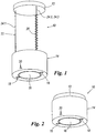
- the hood unit 10 shown in Figures 1 and 2 comprises a support element 12 of a flattened cylinder shape (i.e. a cylindrical body with an oval cross-section), to be fixed in conventional manner to the ceiling of the room in which the hood unit 10 is located, and an actual hood 14 of overall cylindrical shape, of the type operating only in filtration mode (being without the fume discharge conduit), so that the fumes produced by an underlying cooking hob (not shown) are drawn through its lower aperture 16 by conventional suction means enclosed within the actual hood 14, are filtered in conventional manner and are fed into the same room through an aperture (not visible in Figures 1 and 2 ) provided in the upper face of the actual hood 14.
- a support element 12 of a flattened cylinder shape i.e. a cylindrical body with an oval cross-section
- the actual hood 14 is provided with two lighting devices 18 to illuminate the cooking hob.
- the hood unit 10 also comprises means enabling the actual hood 14 to be suspended from the support element 12, these suspension means being indicated overall by 22.
- these suspension means being indicated overall by 22.
- they comprise three suspension wires 24.1, 24.2 and 24.3 (it should be noted that in Figure 1 only two can be seen because the third, 24.3, is covered by the wire 24.2).
- a conventional lifting/lowering mechanism 34 (described hereinafter) is provided to enable the user to vary the elevation of the actual hood 14 by winding or unwinding said wires on or from relative drums or spools, to pass from the situation of Figure 1 (maximum closeness to the cooking hob) to the situation of Figure 2 (maximum distance from the cooking hob) and vice versa. From this latter figure it can be seen that the hood unit 10 resembles a so-called ceiling light fixture and in effect can also perform a lighting function by virtue of the presence of two lighting devices 18 powered by a conventional electric cable 26 ( Figure 1 ).
- the aforesaid mechanism for varying the elevation of the actual hood is conveniently operated by an electric actuator controlled by controls which can form part of the controls 20 or even by controls disposed in a suitable position on the walls of the room in which the hood unit is located (this preventing any oscillation of the hood unit 14 on operating the controls 20) suitable remote control means could also be provided for this purpose.
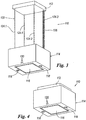
- the hood unit 110 of Figures 3 and 4 differs from the hood unit 10 only in that both the support element 112 and the actual hood 114 are of parallelepiped shape, and the suspension means 122 comprise four wires 124.1, 124.2, 124.3 and 124.4 instead of three.
- the suspension means 122 comprise four wires 124.1, 124.2, 124.3 and 124.4 instead of three.
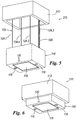
- a variant 210 of the hood unit 110 is shown in Figures 5 and 6 .
- the frame-type support element could also evidently be formed such that the actual hood 114 is completely contained within it.
- the frame-type support element could evidently be of a shape different from rectangular, for example circular, oval or polygonal, this evidently determining the shape of the actual hood which has to be received in the relative frame.
- the support element 212 and/or the actual hood 114 at least a part of their external surface can be made to emit light.
- the hood unit 210 can also perform the function of an actual chandelier. This can be achieved not only with the already stated conventional lighting devices 18, but also by making said external surface part of a transparent or translucent material and positioning behind it, inside the support element 212 and/or the actual hood 114, light emitting means (for example lamps of various types or LEDs).
- light emitting means for example lamps of various types or LEDs.
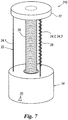
- the hood unit 310 of Figure 7 is similar to the hood unit 10 of Figures 1 and 2 , in the sense that the support element, the actual hood and the suspension means are of equal form to that of the corresponding elements 12, 14 and 22 of these latter figures and for this reason have been indicated by the same reference numerals.
- the hood unit 310 differs from the hood unit 10 because it is of the type operating in suction mode with fume discharge to the outside of the room in which the hood unit is located.
- a fume conduit 28 is provided having the characteristic of being able to be lengthened or shortened (for example formed in the manner of a bellows) in order to follow the vertical movement of the actual hood 14.
- the conduit 28 when in its minimum extension condition can be received in a suitable space provided in the top of the actual hood 14 such that the hood unit 310 appears in the form of a ceiling light fixture such as the hood unit 10 in the condition of Figure 2 .
- FIG 8 shows a more complex embodiment of the hood unit of the present invention, indicated by 410.
- the hood unit 410 differs from the hood unit 310 by the presence of a telescopic casing 30 covering both the suspension means 22 and the fume conduit 28.
- the casing 30 is composed of three coaxial rings 30.1, 30.2 and 30.3, which are mutually superimposed when the actual hood 14 lies in the most elevated position, in which condition they can be received within the interior of this latter, such that the hood unit resembles a ceiling light fixture.
- the casing 30 can also be used if the conduit 28 is absent (i.e. with the hood unit operating only in filtration mode).
- the casing 30 firstly only has an aesthetic function and not that of conveying fumes (function performed by the variable length conduit 28), and secondly is not load-bearing (in the case of the hood unit 410 the load-bearing function being provided by the suspension means 22).
- the casing 30 is carried by the support element 412.
- the support element 412 has a decidedly greater height than support element 12 of the hood unit 10 of Figure 1 , this being because the hood unit 410 operates either in suction mode or in filtration mode, at user choice; in this latter mode (filtration) the air drawn in through the aperture 16 of the actual hood 14 is not discharged to the outside but, once filtered, is again fed into the room through the grille 32.
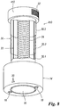
- Figure 9 shows schematically a lifting/lowering device (indicated overall by 34) which, with reference in particular to the hood units 110 and 210 ( Figures 3 and 4 and, respectively, Figures 5 and 6 ), is contained within the casing of the hood 114 and enables the actual hood 114 to be raised and lowered by four parallel vertical wires or cables 124.1, 124.2, 124.3 and 124.4, to cause it to assume the positions illustrated in the relative figures.
- these wires or cables are positioned (viewing the hood unit from above) at the vertices of a rectangle.
- the lifting/lowering device 34 comprises a two-shaft electric stepping motor 36.
- the rotary movement of the two shafts 38, 40 is transmitted via relative belt transmissions 42, 44 to a corresponding shaft 47, 49 on which a relative drum or spool 46, 48 is keyed.
- the two drums 46, 48 are rotatably supported by the hood 114 and are disposed symmetrically, they both presenting a pair of parallel grooves 50, 52, in each of which is fixed an end of a relative wire 124.1, 124.2, 124.3 and 124.4 which, following rotation of the drum 46, 48 in the appropriate direction, winds about the relative groove 50, 52 and unwinds if the drum is rotated in the opposite direction.
- Each wire 124.1, 124.2, 124.3 and 124.4 also passes about a corresponding return pulley 54.1, 54.2, 54.3 and 54.4 so as to raise vertically upwards at the vertices of said rectangle, to emerge through suitable apertures provided in the hood 114 (so that these wires are visible in Figures 3 and 5 ), the other end of each wire being fixed to the support element 112 or 212. It must also be added that the two wires 124 connected to a given drum are wound about it in opposite directions so that rotation of the drum 46, 48 causes both wires to wind onto or unwind from it.
- lifting/lowering devices different from the aforedescribed lifting/lowering device 34 can be used for the same purpose.
- Figure 10 shows the hood 14 of Figure 1 and 2 in greater detail:
- an upper part 14.1 of the housing 14.4 of the hood 14 is shown in a transparent way (which is suggested by the broken line 14.2).
- this upper part of the hood 14 there is a horizontal intermediate bottom 14.3 where the lifting/lowering device 34 is mounted on. Note that both, this intermediate bottom 14.3 as well as the lifting/lowering device 34 are actually hidden behind and securely covered by the housing 14.4 of the hood 14 and thereby do not perturb the appearance of the hood and also do not cause a threat for the user of this hood due to moving parts.
- This lifting/lowering device 34 (being equal or similar to that of Figure 9 and thus, being indicated by the same reference numeral, which is also the case for the parts of this device 34) enables the actual hood 14 to be raised and lowered by the four parallel vertical wires or cables 124.1, 124.2, 124.3 and 124.4 (note that different from Figures 1 and 2 where the suspension means 22 consists of three wires 24.1, 24.2 and 24.3 in the drawing of Figure 10 the suspension means 122 has the four wires 124.1, 124.2, 124.3 and 124.4 as of device 34 shown in Figure 9 ).
- means can be provided for remotely controlling the electric motor 36 and other possible electrical actuators provided in the lifting/lowering hood unit of the present invention to perform other functions.
Landscapes
- Engineering & Computer Science (AREA)
- Chemical & Material Sciences (AREA)
- Combustion & Propulsion (AREA)
- Mechanical Engineering (AREA)
- General Engineering & Computer Science (AREA)
- Ventilation (AREA)
- Control Of Vending Devices And Auxiliary Devices For Vending Devices (AREA)
Description
- The present invention relates to kitchen hood units according to the preamble of claim 1, both of suction type and of filter type.
- A kitchen hood unit of this kind is shown in
EP 2 161 507 A2 , but which forms prior art under Art. 54(3) EPC, only. Other relevant state of the art is found inCN101101134A ,JP 2008 128579A WO 2007/148842A1 . - So-called "Island" hoods are known for installation in the centre of a room, spaced from the walls, and have a chimney rigid with the actual hood, the upper or other end of the chimney being fixed to the ceiling. The chimney can be of telescopic form to be able to adjust within determined limits the distance of the hood unit from the ceiling, in order to adapt it to rooms of different height, so that the hood unit can be disposed at an optimal distance from the cooking hob. It should be noted that the installation of an island hood is fairly complicated and requires the intervention of two persons.
- In recent years new hood unit types have been marketed requiring a somewhat different installation method from the classic type, these including so-called "chandelier" hoods. These are hood units which do not comprise a fume evacuation conduit (so that they only act by filtration) and in which the actual hood is suspended from the ceiling by wires or tubes, as in the case of chandeliers.
- These hood units have the advantage of simplified installation in addition to a reduced visual impact. However, because of the lack of the fume evacuation conduit, these hood units have poor performance. Moreover, being suspended, if touched they tend to oscillate, hence special solutions have to be adopted for the relative control means.
- It should also be noted that so-called ceiling hood units exist, having the advantage of minimum visual impact, they being incorporated into the ceiling, however they present certain disadvantages. In fact, they require the presence of a false ceiling and moreover, even though they can discharge the indrawn fumes outside the room, they have limited performance because the hood unit is excessively spaced from the cooking hob and the fumes can fill the entire room before being drawn in. Moreover, for the same reason, cooking fats being present in the vapours can deposit on furniture and walls before reaching the hood unit.
- So-called lifting/lowering island hoods and also wall hoods exist, i.e. provided with a mechanism which enables the user to adjust its elevation above the cooking hob, so that in the case of intense cooking the hood unit can be lowered to approach the cooking hob and improve its capacity to capture the fumes, whereas when the cooking hob is inactive or in the case of light cooking, with reduced fume development, the hood unit can be lifted/raised to provide more comfortable access to the cooking hob (in particular preventing the user's head from hitting the hood unit). The lifting (or raising) /lowering mechanism can be manual (e.g. of the counterweighted type) or motorized. A version of the lifting/lowering island hood with counterweight is produced by WESCO, while MIELE produces a motorized version.
- It should however be noted that this type of hood unit has the drawback of being rather expensive.
- An object of the present invention is to provide a hood unit, the elevation of which can however be varied by the user, so that it also becomes a lifting /lowering hood unit.
- This object is attained by a kitchen hood unit according to the present invention, comprising an actual hood and suspension means for suspending it from a support element to be fixed to the ceiling of the room in which the hood unit is located, with the features of claim 1.
- Accordingly, the kitchen hood unit according to the invention comprises an actual hood overlying a cooking hob, and suspension means having a length which can be varied by the user to cause the actual hood to approach and withdraw from the cooking hob, said suspension means comprising a lifting/lowering device to vary the length of the suspension means with said lifting/lowering device being contained in the actual hood.
- This renders the present hood unit advantageous in that it is very easy to install: Instead of having to install a support element bearing the lifting/lowering device and also carrying the suspension means with the actual hood, all it is necessary is to fix the suspension means to the ceiling via a support element. Moreover, the hood unit according to the invention is also easy to clean and easy to maintain: During the maintenance there is no need to remove the support from the ceiling or to work on a ladder. All the cleaning and maintenance operations can be performed while the hood is in the lower position and can be easily accessed. If there is the need to remove or change the hood, it can be disconnected/dismounted easily and simply changed against a new one. Finally, this inventive hood unit requires less volume of the transport packaging: By putting the lifting/lowering device inside the hood there is no need to send two different parts, i.e. the hood and the support to the customer.
- While hood units with a the lifting/lowering device are known in the art they have the important disadvantage of being too complicated with respect to its support element which became the central part of the hood and thus, had to support different kind of functional parts like the lifting/lowering device, the exhaust duct etc.
- In contrast to that the hood according to the present invention has one functional part only, i.e. the actual (suspending) hood, and some simple easily accessible, maintainable and replaceable parts like a support element, the suspension means, exhaust ducts etc. This finally results in a (i.e. the) hood of a true "chandelier" style, the concept of which being different from the known complex hoods.
- Advantageous embodiments of the invention are subject of the dependent claims, their wording being herewith explicitly incorporated into the specification in order to avoid the need of unnecessary replications.
- The suspension means conveniently comprise one or more suspension cables or wires, and the lifting/lowering device enables said cables or wires to be rolled onto or unrolled from a relative drum rotatably supported by said support element or by the actual hood, to cause the actual hood to approach or withdraw from the support element. Said device is conveniently motorized.
- One embodiment of the present invention comprises a fume evacuation conduit, the length of which can be varied on the basis of the variation in length of the suspension means.
- The fume evacuation conduit can for example be of a bellows type or of a telescopic type (in both cases without load-bearing function), which is lengthened or shortened as a result respectively of the withdrawal or approach of the actual hood from or towards its support element, as a consequence of the shortening or lengthening of the suspension means.
- Preferably the actual hood is enabled to rise until it lies against the support element. In this condition the hood unit has a bulk reduced to a minimum and resembles a ceiling light fixture. In this case, if a false ceiling is provided, when the actual hood lies in its most elevated position, its lower edge could be arranged such that it does not project from the false ceiling, so that a hood unit is obtained which in this condition resembles a "ceiling" hood.
- The invention will be more apparent from the ensuing description of some embodiments thereof given by way of example. In this description, reference is made to the accompanying drawings, in which:
- Figure 1
- is a perspective view of a first embodiment of the hood unit according to the invention, of the type operating only in the filtration mode, shown in its lowered configuration;
- Figure 2
- shows the same hood unit of
Figure 1 but in its completely raised configuration; - Figure 3
- is a perspective view of a second embodiment of the hood unit of the invention;
- Figure 4
- shows the same hood unit of
Figure 3 in its completely raised configuration; - Figure 5
- is a perspective view of a third embodiment of the hood unit of the invention;
- Figure 6
- shows the same hood unit of
Figure 5 in its completely raised configuration; - Figure 7
- is a perspective view of a fourth embodiment of the hood unit of the invention, similar to that of
Figures 1 and 2 but able to operate in suction mode, being provided with fume evacuation conduits; - Figure 8
- is a perspective view of a fifth embodiment of the hood unit of the invention, also of the suction type and provided with a telescopic casing, shown partly cut away, which covers the suspension means and the fume evacuation conduit;
- Figure 9
- is an enlarged schematic plan view from above showing a lifting/ lowering device forming part of the suspension means, which if these latter are of the wire type, enables the user to vary the elevation of the actual hood; and
- Figure 10
- is a perspective view of a hood unit according to the invention, being similar to the first embodiment shown in
Figures 1 and 2 , but shown with a partly transparent portion of the housing of the proper hood. - The
hood unit 10 shown inFigures 1 and 2 comprises asupport element 12 of a flattened cylinder shape (i.e. a cylindrical body with an oval cross-section), to be fixed in conventional manner to the ceiling of the room in which thehood unit 10 is located, and anactual hood 14 of overall cylindrical shape, of the type operating only in filtration mode (being without the fume discharge conduit), so that the fumes produced by an underlying cooking hob (not shown) are drawn through itslower aperture 16 by conventional suction means enclosed within theactual hood 14, are filtered in conventional manner and are fed into the same room through an aperture (not visible inFigures 1 and 2 ) provided in the upper face of theactual hood 14. In the specific illustrated example, theactual hood 14 is provided with twolighting devices 18 to illuminate the cooking hob.Conventional controls 20, positioned in this specific case on the lateral surface of theactual hood 14, enable activation/deactivation of said suction means, of thelighting devices 18 and, if required, of other devices having specific functions. - From
Figures 1 and 2 it can also be seen that thehood unit 10 also comprises means enabling theactual hood 14 to be suspended from thesupport element 12, these suspension means being indicated overall by 22. In this specific case they comprise three suspension wires 24.1, 24.2 and 24.3 (it should be noted that inFigure 1 only two can be seen because the third, 24.3, is covered by the wire 24.2). - In the interior of the actual hood 14 a conventional lifting/lowering mechanism 34 (described hereinafter) is provided to enable the user to vary the elevation of the
actual hood 14 by winding or unwinding said wires on or from relative drums or spools, to pass from the situation ofFigure 1 (maximum closeness to the cooking hob) to the situation ofFigure 2 (maximum distance from the cooking hob) and vice versa. From this latter figure it can be seen that thehood unit 10 resembles a so-called ceiling light fixture and in effect can also perform a lighting function by virtue of the presence of twolighting devices 18 powered by a conventional electric cable 26 (Figure 1 ). It should be noted that if the room containing the hood unit is provided with a false ceiling, an arrangement can be made whereby when theactual hood 14 is in its highest elevation position (which could also be less than that ofFigure 2 ), the lower edge of this latter 14 coincides essentially with the lower edge of the false ceiling, so that under these conditions the hood unit has the appearance of a "ceiling hood". - The aforesaid mechanism for varying the elevation of the actual hood is conveniently operated by an electric actuator controlled by controls which can form part of the
controls 20 or even by controls disposed in a suitable position on the walls of the room in which the hood unit is located (this preventing any oscillation of thehood unit 14 on operating the controls 20) suitable remote control means could also be provided for this purpose. - The
hood unit 110 ofFigures 3 and 4 differs from thehood unit 10 only in that both thesupport element 112 and theactual hood 114 are of parallelepiped shape, and the suspension means 122 comprise four wires 124.1, 124.2, 124.3 and 124.4 instead of three. For the remainder, inFigures 3 and 4 those elements equal or similar to those ofFigures 1 and 2 are indicated by the same reference numerals as these latter figures, plus 100. - A
variant 210 of thehood unit 110 is shown inFigures 5 and 6 . This differs by the presence of asupport element 212 in the form of a rectangular frame, able to partly receive (in this specific case) the actual hood 112 (it should be noted that in these figures, elements equal to those of thehood unit 110 ofFigures 3 and 4 are indicated by the same reference numerals). The frame-type support element could also evidently be formed such that theactual hood 114 is completely contained within it. The frame-type support element could evidently be of a shape different from rectangular, for example circular, oval or polygonal, this evidently determining the shape of the actual hood which has to be received in the relative frame. - Returning to
Figures 5 and 6 , it should be noted that for thesupport element 212 and/or theactual hood 114, at least a part of their external surface can be made to emit light. In this manner thehood unit 210 can also perform the function of an actual chandelier. This can be achieved not only with the already statedconventional lighting devices 18, but also by making said external surface part of a transparent or translucent material and positioning behind it, inside thesupport element 212 and/or theactual hood 114, light emitting means (for example lamps of various types or LEDs). A similar facility also evidently exists for the other hood unit types shown in the accompanying drawings. - The
hood unit 310 ofFigure 7 is similar to thehood unit 10 ofFigures 1 and 2 , in the sense that the support element, the actual hood and the suspension means are of equal form to that of thecorresponding elements hood unit 310 differs from thehood unit 10 because it is of the type operating in suction mode with fume discharge to the outside of the room in which the hood unit is located. For this purpose afume conduit 28 is provided having the characteristic of being able to be lengthened or shortened (for example formed in the manner of a bellows) in order to follow the vertical movement of theactual hood 14. In particular, theconduit 28 when in its minimum extension condition can be received in a suitable space provided in the top of theactual hood 14 such that thehood unit 310 appears in the form of a ceiling light fixture such as thehood unit 10 in the condition ofFigure 2 . -
Figure 8 shows a more complex embodiment of the hood unit of the present invention, indicated by 410. In this figure, elements equal to those of thehood unit 310 are indicated by the same reference numerals. Thehood unit 410 differs from thehood unit 310 by the presence of atelescopic casing 30 covering both the suspension means 22 and thefume conduit 28. In the specific illustrated example, thecasing 30 is composed of three coaxial rings 30.1, 30.2 and 30.3, which are mutually superimposed when theactual hood 14 lies in the most elevated position, in which condition they can be received within the interior of this latter, such that the hood unit resembles a ceiling light fixture. It should be noted that thecasing 30 can also be used if theconduit 28 is absent (i.e. with the hood unit operating only in filtration mode). - An observer viewing the
hood unit 410 could mistake it for a conventional lifting/lowering island hood with a telescopic chimney, which is in fact not the case, because thecasing 30 firstly only has an aesthetic function and not that of conveying fumes (function performed by the variable length conduit 28), and secondly is not load-bearing (in the case of thehood unit 410 the load-bearing function being provided by the suspension means 22). In the specific illustrated example, thecasing 30 is carried by thesupport element 412. As can be seen fromFigure 8 , thesupport element 412 has a decidedly greater height thansupport element 12 of thehood unit 10 ofFigure 1 , this being because thehood unit 410 operates either in suction mode or in filtration mode, at user choice; in this latter mode (filtration) the air drawn in through theaperture 16 of theactual hood 14 is not discharged to the outside but, once filtered, is again fed into the room through thegrille 32. -
Figure 9 shows schematically a lifting/lowering device (indicated overall by 34) which, with reference in particular to thehood units 110 and 210 (Figures 3 and 4 and, respectively,Figures 5 and 6 ), is contained within the casing of thehood 114 and enables theactual hood 114 to be raised and lowered by four parallel vertical wires or cables 124.1, 124.2, 124.3 and 124.4, to cause it to assume the positions illustrated in the relative figures. In this specific case, these wires or cables are positioned (viewing the hood unit from above) at the vertices of a rectangle. - The lifting/lowering
device 34 comprises a two-shaftelectric stepping motor 36. The rotary movement of the twoshafts relative belt transmissions shaft spool drums hood 114 and are disposed symmetrically, they both presenting a pair ofparallel grooves drum relative groove Figures 3 and5 ), the other end of each wire being fixed to thesupport element drum - From the aforegoing it is apparent that the two
drums electric motor 36. Hence the wires 124 can be wound onto or unwound from therelative drums motor 36, to obtain as a result the raising or, respectively, lowering of theactual hood 114 relative to therespective support element circle 56 visible inFigure 9 indicates merely that the lifting/loweringdevice 34 leaves space for possible passage of a fume evacuation conduit. - It is apparent that other types of lifting/lowering devices different from the aforedescribed lifting/lowering
device 34 can be used for the same purpose. -
Figure 10 shows thehood 14 ofFigure 1 and 2 in greater detail: In order to better show the actual position of the lowering and liftingdevice 34 an upper part 14.1 of the housing 14.4 of thehood 14 is shown in a transparent way (which is suggested by the broken line 14.2). In this upper part of thehood 14 there is a horizontal intermediate bottom 14.3 where the lifting/loweringdevice 34 is mounted on. Note that both, this intermediate bottom 14.3 as well as the lifting/loweringdevice 34 are actually hidden behind and securely covered by the housing 14.4 of thehood 14 and thereby do not perturb the appearance of the hood and also do not cause a threat for the user of this hood due to moving parts. - This lifting/lowering device 34 (being equal or similar to that of
Figure 9 and thus, being indicated by the same reference numeral, which is also the case for the parts of this device 34) enables theactual hood 14 to be raised and lowered by the four parallel vertical wires or cables 124.1, 124.2, 124.3 and 124.4 (note that different fromFigures 1 and 2 where the suspension means 22 consists of three wires 24.1, 24.2 and 24.3 in the drawing ofFigure 10 the suspension means 122 has the four wires 124.1, 124.2, 124.3 and 124.4 as ofdevice 34 shown inFigure 9 ). - As already stated, means (not shown for simplicity) can be provided for remotely controlling the
electric motor 36 and other possible electrical actuators provided in the lifting/lowering hood unit of the present invention to perform other functions.
Claims (12)
- A kitchen hood unit (10; 110; 210; 310; 410) comprising an actual hood (14; 114) overlying a cooking hob, and suspension means (22; 122) having a length which can be varied by the user to cause the actual hood (14; 114) to approach and withdraw from the cooking hob, said suspension means comprising a lifting/lowering device (34) to vary the length of the suspension means (22; 122), wherein the suspension means (22; 122) comprise one or more suspension cables or wires (24; 124), wherein the lifting/lowering device (34) enables said cables or wires (24; 124) to be wound or unwound, and wherein the lifting/lowering device (34) comprises, for each cable or wire (24; 124), a relative drum (50, 52) rotatably supported by the actual hood (14; 114) and on which the cable or wire (24; 124) can be wound or unwound, and wherein said lifting/lowering device (34) is contained in the actual hood (14; 114); characterized in that said kitchen hood comprises a common support element (12; 112; 212; 412) to be fixed to the ceiling of the room in which the hood unit (10; 110; 210; 310; 410) is located and wherein the suspension means (22; 122), one end of each being fixed to the common support element (12; 112; 212; 412), serve for suspending said actual hood from said support element,.
- The use of a kitchen hood unit (10; 110; 210; 310; 410) as claimed in claim 1, wherein for installation of the hood unit in a room provided with a false ceiling, the hood unit is adapted to be configured such that when the actual hood (14; 114) lies in its position of maximum elevation, the length of the suspension means (22; 122) is reduced to such an extent that the lower edge of the actual hood (14; 114) has substantially the same elevation as the lower edge of the false ceiling.
- A kitchen hood unit (210) as claimed in claim 1, wherein the support element (212) has the shape of a frame and is adapted to receive all or part of the actual hood (114).
- A kitchen hood unit as claimed in claim 3, wherein the frame-shaped support element (212) is of polygonal or circular form.
- A kitchen hood unit (10; 110; 210; 310; 410) as claimed in claim 1, wherein the device (34) comprises an electric motor (36).
- A kitchen hood unit (110; 210) as claimed in claims 1 and 5, wherein the suspension cables or wires are four in number (124.1; 124.2; 124.3; 124.4), positioned at the vertices of a square or rectangle, said cables or wires being connected in pairs to a relative drum (46, 48) rotatably supported by the support element (112; 212) and provided with a pair of parallel grooves (50, 52), in each of which a relative suspension cable or wire (124.1; 124.2; 124.3; 124.4) can wind and unwind, the two wires or cables of any given drum (46, 48) being wound in the relative groove (50, 52) in opposite directions, the electric motor (36) having two shafts, each shaft (38, 40) being adapted to transmit its rotary movement, via suitable transmission means (42, 44), to one of two said drums (46, 48).
- A kitchen hood unit (10; 110; 210; 310; 410) as claimed in claim 5, wherein means are provided enabling the electric motor (36) to be remotely and preferably wirelessly controlled.
- A kitchen hood unit (310; 410) as claimed in claim 1, wherein a fume evacuation conduit (28) is provided, the length of which is arranged to undergo variation on the basis of the variation in length of the suspension means (22) whereby the fume evacuation conduit (28) is of bellows form or of telescopic form.
- A kitchen hood unit as claimed in claim 1, wherein a telescopic casing is provided covering the suspension means (22;122).
- A kitchen hood unit (410) as claimed in claim 8, wherein a telescopic casing (30) is provided covering both the suspension means (22) and the fume evacuation conduit (28).
- A kitchen hood unit (10; 110; 210; 310; 410) as claimed in claim 1, wherein lighting devices (18; 118) are provided in the actual hood (14; 114) and/or in the support element (12; 112; 212; 412).
- A kitchen hood unit (10; 110; 210; 310; 410) as claimed in claim 1, wherein at least a part (18) of the external surface of the actual hood (14; 114) and/or of the support element (12; 112; 212; 412) is arranged to emit light and/or is translucent or transparent.
Applications Claiming Priority (2)
| Application Number | Priority Date | Filing Date | Title |
|---|---|---|---|
| IT002078A ITMI20092078A1 (en) | 2009-11-26 | 2009-11-26 | "HOOD WITH SALES-DROPET DEVICE" |
| PCT/EP2010/007175 WO2011063969A1 (en) | 2009-11-26 | 2010-11-26 | Hood unit with lifting/lowering device in the hood |
Publications (2)
| Publication Number | Publication Date |
|---|---|
| EP2504628A1 EP2504628A1 (en) | 2012-10-03 |
| EP2504628B1 true EP2504628B1 (en) | 2017-05-03 |
Family
ID=42342471
Family Applications (2)
| Application Number | Title | Priority Date | Filing Date |
|---|---|---|---|
| EP10005445A Withdrawn EP2327936A1 (en) | 2009-11-26 | 2010-05-26 | Hood unit with raising / lowering device |
| EP10784989.5A Active EP2504628B1 (en) | 2009-11-26 | 2010-11-26 | Hood unit with lifting/lowering device in the hood |
Family Applications Before (1)
| Application Number | Title | Priority Date | Filing Date |
|---|---|---|---|
| EP10005445A Withdrawn EP2327936A1 (en) | 2009-11-26 | 2010-05-26 | Hood unit with raising / lowering device |
Country Status (3)
| Country | Link |
|---|---|
| EP (2) | EP2327936A1 (en) |
| IT (1) | ITMI20092078A1 (en) |
| WO (1) | WO2011063969A1 (en) |
Families Citing this family (13)
| Publication number | Priority date | Publication date | Assignee | Title |
|---|---|---|---|---|
| DE102015200639A1 (en) * | 2015-01-16 | 2016-07-21 | Berbel Ablufttechnik Gmbh | Device for extracting exhaust air |
| DE102016103125A1 (en) * | 2016-02-23 | 2017-08-24 | Miele & Cie. Kg | Support cable for an extractor hood and extractor hood |
| ITUA20161328A1 (en) * | 2016-03-03 | 2017-09-03 | Elica Spa | Hood for domestic environments equipped with a command and control unit external to the hood |
| ITUA20162433A1 (en) * | 2016-04-08 | 2017-10-08 | Faber Spa | REFINED HOOD OF SALISCENDI TYPE OR UP AND DOWN |
| JP7004279B2 (en) * | 2016-08-31 | 2022-01-21 | 富士工業株式会社 | Range hood and its manufacturing method |
| DE102016219717B4 (en) * | 2016-10-11 | 2021-10-28 | BSH Hausgeräte GmbH | Extractor device |
| IL250014A0 (en) * | 2017-01-09 | 2017-03-30 | Unito Smart Tech Limited | Improved kitchen hood |
| DE102017203639B4 (en) | 2017-03-07 | 2021-05-06 | BSH Hausgeräte GmbH | Height adjustment device for an extractor hood, extractor hood and method for adjusting the position of an extractor hood |
| DE102017122667B3 (en) * | 2017-09-29 | 2018-12-06 | Miele & Cie. Kg | Strain relief device for a fume extraction device, extractor device and method for mounting a fume extraction device |
| ES2723714B2 (en) | 2018-02-23 | 2021-10-15 | Inoxpan S L | SMOKE EXTRACTOR HOOD WITH AUTOMATIC DISPLACEMENT OF THE LOWER COVER |
| DE102018114805B4 (en) | 2018-06-20 | 2026-07-09 | Miele & Cie. Kg | Island cooker hood and methods for operating an island cooker hood |
| EP3842694A1 (en) | 2019-12-27 | 2021-06-30 | Silverline Endüstri ve Ticaret A.S. | Ceiling type range hood with improved hanging and installation system |
| DE102021118205B4 (en) * | 2021-07-14 | 2025-05-08 | Berbel Ablufttechnik Gmbh | Extractor hood with loudspeaker |
Citations (2)
| Publication number | Priority date | Publication date | Assignee | Title |
|---|---|---|---|---|
| DE102008027470A1 (en) * | 2008-06-09 | 2009-12-10 | BSH Bosch und Siemens Hausgeräte GmbH | Fume extractor hood e.g. island chimney, for use in fireplace, has suspension device comprising electric motor with cable pull and deflection roller for adjusting height of suction area housing, where hood is operated in height |
| EP2161507A2 (en) * | 2008-09-01 | 2010-03-10 | BSH Bosch und Siemens Hausgeräte GmbH | Vapour extraction device, especially ceiling mounted island hood, and module assembly with such a vapour extraction device |
Family Cites Families (11)
| Publication number | Priority date | Publication date | Assignee | Title |
|---|---|---|---|---|
| DE3345771C1 (en) * | 1983-12-17 | 1985-09-05 | Hüppe GmbH, 2900 Oldenburg | Extractor hood in particular for kitchens |
| US4612909A (en) * | 1985-02-22 | 1986-09-23 | Lee Chi Min | Room exhaust duct |
| DE4105004A1 (en) * | 1991-02-19 | 1992-08-20 | Kueppersbusch | Extractor hood for cooker - has system of balancing weights and pulleys or springs and friction wheels for adjusting its height |
| IT1263870B (en) * | 1993-03-31 | 1996-09-04 | APPLIANCE FOR THE EXTRACTION OF SMOKES AND EXHALATIONS, PARTICULARLY FOR FOOD COOKING | |
| DE10309226A1 (en) * | 2002-12-20 | 2004-07-01 | BSH Bosch und Siemens Hausgeräte GmbH | Electric cooker hob has fume extractor and telescopic height adjustment means to raise hob for food preparation |
| KR100600002B1 (en) * | 2005-05-16 | 2006-07-19 | 서선자 | Range hood suction device |
| KR200405831Y1 (en) * | 2005-10-12 | 2006-01-11 | 신현구 | Roaster Exhaust |
| KR100766146B1 (en) * | 2006-06-19 | 2007-10-10 | 태영주식회사 | Retractable Range Hoods for Kitchen |
| CN101101134A (en) * | 2006-07-04 | 2008-01-09 | Ezentec株式会社 | kitchen air exhaust hood |
| JP2008128579A (en) * | 2006-11-22 | 2008-06-05 | Tokyo Electric Power Co Inc:The | Ventilation equipment |
| CN201152570Y (en) * | 2007-10-24 | 2008-11-19 | 刘大伟 | Telescopic fume guiding cover of cooking fume exhauster |
-
2009
- 2009-11-26 IT IT002078A patent/ITMI20092078A1/en unknown
-
2010
- 2010-05-26 EP EP10005445A patent/EP2327936A1/en not_active Withdrawn
- 2010-11-26 EP EP10784989.5A patent/EP2504628B1/en active Active
- 2010-11-26 WO PCT/EP2010/007175 patent/WO2011063969A1/en not_active Ceased
Patent Citations (2)
| Publication number | Priority date | Publication date | Assignee | Title |
|---|---|---|---|---|
| DE102008027470A1 (en) * | 2008-06-09 | 2009-12-10 | BSH Bosch und Siemens Hausgeräte GmbH | Fume extractor hood e.g. island chimney, for use in fireplace, has suspension device comprising electric motor with cable pull and deflection roller for adjusting height of suction area housing, where hood is operated in height |
| EP2161507A2 (en) * | 2008-09-01 | 2010-03-10 | BSH Bosch und Siemens Hausgeräte GmbH | Vapour extraction device, especially ceiling mounted island hood, and module assembly with such a vapour extraction device |
Also Published As
| Publication number | Publication date |
|---|---|
| EP2327936A1 (en) | 2011-06-01 |
| ITMI20092078A1 (en) | 2011-05-27 |
| EP2504628A1 (en) | 2012-10-03 |
| WO2011063969A1 (en) | 2011-06-03 |
Similar Documents
| Publication | Publication Date | Title |
|---|---|---|
| WO2011063969A1 (en) | Hood unit with lifting/lowering device in the hood | |
| US20140041649A1 (en) | Downdraft system | |
| JP7242982B2 (en) | A lighting device that is connected by a wire and cable system and can be freely raised and lowered and has an air purifier attached. | |
| US9297540B2 (en) | Downdraft system | |
| KR102789242B1 (en) | An air purifier comprising a lifting discharge part | |
| CN101421176B (en) | Grill hook for air conditioner | |
| JP2009533300A (en) | Lifting device provided with lifting reel | |
| CN101101134A (en) | kitchen air exhaust hood | |
| JP5065390B2 (en) | Elevating reel wire entanglement prevention device having four wire structure and elevating reel provided with the same | |
| CN108826244A (en) | Liftable hoisting mechanism and pendent lamp and furred ceiling smoke machine with it | |
| KR20250141666A (en) | Air Cleaner | |
| KR100766146B1 (en) | Retractable Range Hoods for Kitchen | |
| KR102687748B1 (en) | Air conditioner | |
| TWI386546B (en) | Blinds device | |
| JP6113434B2 (en) | Daylighting equipment | |
| CN109519993A (en) | A kind of Liftable type kitchen ventilator | |
| KR200450059Y1 (en) | Electric laundry dryer | |
| CA2814915C (en) | Downdraft system | |
| US20070134093A1 (en) | Device and method for raising and lowering ceiling fixtures | |
| AU2014259588A1 (en) | Downdraft system | |
| EP4647646A1 (en) | Workstation for video terminal operators | |
| EP3531027A1 (en) | Extractor hood with automatic movement of the bottom cover | |
| KR200425028Y1 (en) | Retractable Range Hoods for Kitchen | |
| JPH0972569A (en) | Ceiling embedded air conditioner | |
| KR100557867B1 (en) | Movable Roaster Exhaust |
Legal Events
| Date | Code | Title | Description |
|---|---|---|---|
| PUAI | Public reference made under article 153(3) epc to a published international application that has entered the european phase |
Free format text: ORIGINAL CODE: 0009012 |
|
| 17P | Request for examination filed |
Effective date: 20120329 |
|
| AK | Designated contracting states |
Kind code of ref document: A1 Designated state(s): AL AT BE BG CH CY CZ DE DK EE ES FI FR GB GR HR HU IE IS IT LI LT LU LV MC MK MT NL NO PL PT RO RS SE SI SK SM TR |
|
| DAX | Request for extension of the european patent (deleted) | ||
| 17Q | First examination report despatched |
Effective date: 20140521 |
|
| GRAP | Despatch of communication of intention to grant a patent |
Free format text: ORIGINAL CODE: EPIDOSNIGR1 |
|
| STAA | Information on the status of an ep patent application or granted ep patent |
Free format text: STATUS: GRANT OF PATENT IS INTENDED |
|
| INTG | Intention to grant announced |
Effective date: 20161123 |
|
| GRAS | Grant fee paid |
Free format text: ORIGINAL CODE: EPIDOSNIGR3 |
|
| GRAA | (expected) grant |
Free format text: ORIGINAL CODE: 0009210 |
|
| STAA | Information on the status of an ep patent application or granted ep patent |
Free format text: STATUS: THE PATENT HAS BEEN GRANTED |
|
| AK | Designated contracting states |
Kind code of ref document: B1 Designated state(s): AL AT BE BG CH CY CZ DE DK EE ES FI FR GB GR HR HU IE IS IT LI LT LU LV MC MK MT NL NO PL PT RO RS SE SI SK SM TR |
|
| REG | Reference to a national code |
Ref country code: GB Ref legal event code: FG4D |
|
| REG | Reference to a national code |
Ref country code: AT Ref legal event code: REF Ref document number: 890419 Country of ref document: AT Kind code of ref document: T Effective date: 20170515 Ref country code: CH Ref legal event code: EP |
|
| REG | Reference to a national code |
Ref country code: IE Ref legal event code: FG4D |
|
| REG | Reference to a national code |
Ref country code: DE Ref legal event code: R096 Ref document number: 602010042091 Country of ref document: DE |
|
| REG | Reference to a national code |
Ref country code: NL Ref legal event code: MP Effective date: 20170503 |
|
| REG | Reference to a national code |
Ref country code: AT Ref legal event code: MK05 Ref document number: 890419 Country of ref document: AT Kind code of ref document: T Effective date: 20170503 |
|
| REG | Reference to a national code |
Ref country code: LT Ref legal event code: MG4D |
|
| PG25 | Lapsed in a contracting state [announced via postgrant information from national office to epo] |
Ref country code: LT Free format text: LAPSE BECAUSE OF FAILURE TO SUBMIT A TRANSLATION OF THE DESCRIPTION OR TO PAY THE FEE WITHIN THE PRESCRIBED TIME-LIMIT Effective date: 20170503 Ref country code: GR Free format text: LAPSE BECAUSE OF FAILURE TO SUBMIT A TRANSLATION OF THE DESCRIPTION OR TO PAY THE FEE WITHIN THE PRESCRIBED TIME-LIMIT Effective date: 20170804 Ref country code: HR Free format text: LAPSE BECAUSE OF FAILURE TO SUBMIT A TRANSLATION OF THE DESCRIPTION OR TO PAY THE FEE WITHIN THE PRESCRIBED TIME-LIMIT Effective date: 20170503 Ref country code: NO Free format text: LAPSE BECAUSE OF FAILURE TO SUBMIT A TRANSLATION OF THE DESCRIPTION OR TO PAY THE FEE WITHIN THE PRESCRIBED TIME-LIMIT Effective date: 20170803 Ref country code: AT Free format text: LAPSE BECAUSE OF FAILURE TO SUBMIT A TRANSLATION OF THE DESCRIPTION OR TO PAY THE FEE WITHIN THE PRESCRIBED TIME-LIMIT Effective date: 20170503 Ref country code: ES Free format text: LAPSE BECAUSE OF FAILURE TO SUBMIT A TRANSLATION OF THE DESCRIPTION OR TO PAY THE FEE WITHIN THE PRESCRIBED TIME-LIMIT Effective date: 20170503 Ref country code: FI Free format text: LAPSE BECAUSE OF FAILURE TO SUBMIT A TRANSLATION OF THE DESCRIPTION OR TO PAY THE FEE WITHIN THE PRESCRIBED TIME-LIMIT Effective date: 20170503 |
|
| REG | Reference to a national code |
Ref country code: FR Ref legal event code: PLFP Year of fee payment: 8 |
|
| PG25 | Lapsed in a contracting state [announced via postgrant information from national office to epo] |
Ref country code: RS Free format text: LAPSE BECAUSE OF FAILURE TO SUBMIT A TRANSLATION OF THE DESCRIPTION OR TO PAY THE FEE WITHIN THE PRESCRIBED TIME-LIMIT Effective date: 20170503 Ref country code: SE Free format text: LAPSE BECAUSE OF FAILURE TO SUBMIT A TRANSLATION OF THE DESCRIPTION OR TO PAY THE FEE WITHIN THE PRESCRIBED TIME-LIMIT Effective date: 20170503 Ref country code: IS Free format text: LAPSE BECAUSE OF FAILURE TO SUBMIT A TRANSLATION OF THE DESCRIPTION OR TO PAY THE FEE WITHIN THE PRESCRIBED TIME-LIMIT Effective date: 20170903 Ref country code: NL Free format text: LAPSE BECAUSE OF FAILURE TO SUBMIT A TRANSLATION OF THE DESCRIPTION OR TO PAY THE FEE WITHIN THE PRESCRIBED TIME-LIMIT Effective date: 20170503 Ref country code: LV Free format text: LAPSE BECAUSE OF FAILURE TO SUBMIT A TRANSLATION OF THE DESCRIPTION OR TO PAY THE FEE WITHIN THE PRESCRIBED TIME-LIMIT Effective date: 20170503 Ref country code: BG Free format text: LAPSE BECAUSE OF FAILURE TO SUBMIT A TRANSLATION OF THE DESCRIPTION OR TO PAY THE FEE WITHIN THE PRESCRIBED TIME-LIMIT Effective date: 20170803 |
|
| PG25 | Lapsed in a contracting state [announced via postgrant information from national office to epo] |
Ref country code: SK Free format text: LAPSE BECAUSE OF FAILURE TO SUBMIT A TRANSLATION OF THE DESCRIPTION OR TO PAY THE FEE WITHIN THE PRESCRIBED TIME-LIMIT Effective date: 20170503 Ref country code: CZ Free format text: LAPSE BECAUSE OF FAILURE TO SUBMIT A TRANSLATION OF THE DESCRIPTION OR TO PAY THE FEE WITHIN THE PRESCRIBED TIME-LIMIT Effective date: 20170503 Ref country code: DK Free format text: LAPSE BECAUSE OF FAILURE TO SUBMIT A TRANSLATION OF THE DESCRIPTION OR TO PAY THE FEE WITHIN THE PRESCRIBED TIME-LIMIT Effective date: 20170503 Ref country code: EE Free format text: LAPSE BECAUSE OF FAILURE TO SUBMIT A TRANSLATION OF THE DESCRIPTION OR TO PAY THE FEE WITHIN THE PRESCRIBED TIME-LIMIT Effective date: 20170503 Ref country code: RO Free format text: LAPSE BECAUSE OF FAILURE TO SUBMIT A TRANSLATION OF THE DESCRIPTION OR TO PAY THE FEE WITHIN THE PRESCRIBED TIME-LIMIT Effective date: 20170503 |
|
| REG | Reference to a national code |
Ref country code: DE Ref legal event code: R097 Ref document number: 602010042091 Country of ref document: DE |
|
| PG25 | Lapsed in a contracting state [announced via postgrant information from national office to epo] |
Ref country code: SM Free format text: LAPSE BECAUSE OF FAILURE TO SUBMIT A TRANSLATION OF THE DESCRIPTION OR TO PAY THE FEE WITHIN THE PRESCRIBED TIME-LIMIT Effective date: 20170503 |
|
| PLBE | No opposition filed within time limit |
Free format text: ORIGINAL CODE: 0009261 |
|
| STAA | Information on the status of an ep patent application or granted ep patent |
Free format text: STATUS: NO OPPOSITION FILED WITHIN TIME LIMIT |
|
| 26N | No opposition filed |
Effective date: 20180206 |
|
| PG25 | Lapsed in a contracting state [announced via postgrant information from national office to epo] |
Ref country code: SI Free format text: LAPSE BECAUSE OF FAILURE TO SUBMIT A TRANSLATION OF THE DESCRIPTION OR TO PAY THE FEE WITHIN THE PRESCRIBED TIME-LIMIT Effective date: 20170503 |
|
| PG25 | Lapsed in a contracting state [announced via postgrant information from national office to epo] |
Ref country code: MC Free format text: LAPSE BECAUSE OF FAILURE TO SUBMIT A TRANSLATION OF THE DESCRIPTION OR TO PAY THE FEE WITHIN THE PRESCRIBED TIME-LIMIT Effective date: 20170503 |
|
| PG25 | Lapsed in a contracting state [announced via postgrant information from national office to epo] |
Ref country code: LU Free format text: LAPSE BECAUSE OF NON-PAYMENT OF DUE FEES Effective date: 20171126 |
|
| REG | Reference to a national code |
Ref country code: BE Ref legal event code: MM Effective date: 20171130 |
|
| REG | Reference to a national code |
Ref country code: IE Ref legal event code: MM4A |
|
| PG25 | Lapsed in a contracting state [announced via postgrant information from national office to epo] |
Ref country code: MT Free format text: LAPSE BECAUSE OF NON-PAYMENT OF DUE FEES Effective date: 20171126 |
|
| PG25 | Lapsed in a contracting state [announced via postgrant information from national office to epo] |
Ref country code: IE Free format text: LAPSE BECAUSE OF NON-PAYMENT OF DUE FEES Effective date: 20171126 |
|
| PG25 | Lapsed in a contracting state [announced via postgrant information from national office to epo] |
Ref country code: BE Free format text: LAPSE BECAUSE OF NON-PAYMENT OF DUE FEES Effective date: 20171130 |
|
| PG25 | Lapsed in a contracting state [announced via postgrant information from national office to epo] |
Ref country code: HU Free format text: LAPSE BECAUSE OF FAILURE TO SUBMIT A TRANSLATION OF THE DESCRIPTION OR TO PAY THE FEE WITHIN THE PRESCRIBED TIME-LIMIT; INVALID AB INITIO Effective date: 20101126 |
|
| PG25 | Lapsed in a contracting state [announced via postgrant information from national office to epo] |
Ref country code: CY Free format text: LAPSE BECAUSE OF NON-PAYMENT OF DUE FEES Effective date: 20170503 |
|
| PG25 | Lapsed in a contracting state [announced via postgrant information from national office to epo] |
Ref country code: MK Free format text: LAPSE BECAUSE OF FAILURE TO SUBMIT A TRANSLATION OF THE DESCRIPTION OR TO PAY THE FEE WITHIN THE PRESCRIBED TIME-LIMIT Effective date: 20170503 |
|
| PG25 | Lapsed in a contracting state [announced via postgrant information from national office to epo] |
Ref country code: PT Free format text: LAPSE BECAUSE OF FAILURE TO SUBMIT A TRANSLATION OF THE DESCRIPTION OR TO PAY THE FEE WITHIN THE PRESCRIBED TIME-LIMIT Effective date: 20170503 |
|
| PG25 | Lapsed in a contracting state [announced via postgrant information from national office to epo] |
Ref country code: AL Free format text: LAPSE BECAUSE OF FAILURE TO SUBMIT A TRANSLATION OF THE DESCRIPTION OR TO PAY THE FEE WITHIN THE PRESCRIBED TIME-LIMIT Effective date: 20170503 |
|
| P01 | Opt-out of the competence of the unified patent court (upc) registered |
Effective date: 20230602 |
|
| REG | Reference to a national code |
Ref country code: CH Ref legal event code: U11 Free format text: ST27 STATUS EVENT CODE: U-0-0-U10-U11 (AS PROVIDED BY THE NATIONAL OFFICE) Effective date: 20251201 |
|
| PGFP | Annual fee paid to national office [announced via postgrant information from national office to epo] |
Ref country code: DE Payment date: 20250919 Year of fee payment: 16 |
|
| PGFP | Annual fee paid to national office [announced via postgrant information from national office to epo] |
Ref country code: GB Payment date: 20251120 Year of fee payment: 16 |
|
| PGFP | Annual fee paid to national office [announced via postgrant information from national office to epo] |
Ref country code: IT Payment date: 20251128 Year of fee payment: 16 |
|
| PGFP | Annual fee paid to national office [announced via postgrant information from national office to epo] |
Ref country code: FR Payment date: 20251120 Year of fee payment: 16 |
|
| PGFP | Annual fee paid to national office [announced via postgrant information from national office to epo] |
Ref country code: TR Payment date: 20251120 Year of fee payment: 16 |
|
| PGFP | Annual fee paid to national office [announced via postgrant information from national office to epo] |
Ref country code: CH Payment date: 20251201 Year of fee payment: 16 |
|
| PGFP | Annual fee paid to national office [announced via postgrant information from national office to epo] |
Ref country code: PL Payment date: 20251119 Year of fee payment: 16 |