EP2504613B1 - Verification pin - Google Patents
Verification pin Download PDFInfo
- Publication number
- EP2504613B1 EP2504613B1 EP10787942.1A EP10787942A EP2504613B1 EP 2504613 B1 EP2504613 B1 EP 2504613B1 EP 10787942 A EP10787942 A EP 10787942A EP 2504613 B1 EP2504613 B1 EP 2504613B1
- Authority
- EP
- European Patent Office
- Prior art keywords
- retainer
- pin
- tube
- quick connector
- disposed
- Prior art date
- Legal status (The legal status is an assumption and is not a legal conclusion. Google has not performed a legal analysis and makes no representation as to the accuracy of the status listed.)
- Active
Links
Images


Classifications
-
- F—MECHANICAL ENGINEERING; LIGHTING; HEATING; WEAPONS; BLASTING
- F16—ENGINEERING ELEMENTS AND UNITS; GENERAL MEASURES FOR PRODUCING AND MAINTAINING EFFECTIVE FUNCTIONING OF MACHINES OR INSTALLATIONS; THERMAL INSULATION IN GENERAL
- F16L—PIPES; JOINTS OR FITTINGS FOR PIPES; SUPPORTS FOR PIPES, CABLES OR PROTECTIVE TUBING; MEANS FOR THERMAL INSULATION IN GENERAL
- F16L37/00—Couplings of the quick-acting type
- F16L37/08—Couplings of the quick-acting type in which the connection between abutting or axially overlapping ends is maintained by locking members
- F16L37/084—Couplings of the quick-acting type in which the connection between abutting or axially overlapping ends is maintained by locking members combined with automatic locking
- F16L37/098—Couplings of the quick-acting type in which the connection between abutting or axially overlapping ends is maintained by locking members combined with automatic locking by means of flexible hooks
- F16L37/0985—Couplings of the quick-acting type in which the connection between abutting or axially overlapping ends is maintained by locking members combined with automatic locking by means of flexible hooks the flexible hook extending radially inwardly from an outer part and engaging a bead, recess or the like on an inner part
- F16L37/0987—Couplings of the quick-acting type in which the connection between abutting or axially overlapping ends is maintained by locking members combined with automatic locking by means of flexible hooks the flexible hook extending radially inwardly from an outer part and engaging a bead, recess or the like on an inner part the flexible hook being progressively compressed by axial tensile loads acting on the coupling
-
- F—MECHANICAL ENGINEERING; LIGHTING; HEATING; WEAPONS; BLASTING
- F16—ENGINEERING ELEMENTS AND UNITS; GENERAL MEASURES FOR PRODUCING AND MAINTAINING EFFECTIVE FUNCTIONING OF MACHINES OR INSTALLATIONS; THERMAL INSULATION IN GENERAL
- F16L—PIPES; JOINTS OR FITTINGS FOR PIPES; SUPPORTS FOR PIPES, CABLES OR PROTECTIVE TUBING; MEANS FOR THERMAL INSULATION IN GENERAL
- F16L37/00—Couplings of the quick-acting type
- F16L37/08—Couplings of the quick-acting type in which the connection between abutting or axially overlapping ends is maintained by locking members
- F16L37/084—Couplings of the quick-acting type in which the connection between abutting or axially overlapping ends is maintained by locking members combined with automatic locking
- F16L37/098—Couplings of the quick-acting type in which the connection between abutting or axially overlapping ends is maintained by locking members combined with automatic locking by means of flexible hooks
-
- F—MECHANICAL ENGINEERING; LIGHTING; HEATING; WEAPONS; BLASTING
- F16—ENGINEERING ELEMENTS AND UNITS; GENERAL MEASURES FOR PRODUCING AND MAINTAINING EFFECTIVE FUNCTIONING OF MACHINES OR INSTALLATIONS; THERMAL INSULATION IN GENERAL
- F16L—PIPES; JOINTS OR FITTINGS FOR PIPES; SUPPORTS FOR PIPES, CABLES OR PROTECTIVE TUBING; MEANS FOR THERMAL INSULATION IN GENERAL
- F16L37/00—Couplings of the quick-acting type
- F16L37/08—Couplings of the quick-acting type in which the connection between abutting or axially overlapping ends is maintained by locking members
- F16L37/12—Couplings of the quick-acting type in which the connection between abutting or axially overlapping ends is maintained by locking members using hooks, pawls, or other movable or insertable locking members
- F16L37/14—Joints secured by inserting between mating surfaces an element, e.g. a piece of wire, a pin, a chain
-
- F—MECHANICAL ENGINEERING; LIGHTING; HEATING; WEAPONS; BLASTING
- F16—ENGINEERING ELEMENTS AND UNITS; GENERAL MEASURES FOR PRODUCING AND MAINTAINING EFFECTIVE FUNCTIONING OF MACHINES OR INSTALLATIONS; THERMAL INSULATION IN GENERAL
- F16L—PIPES; JOINTS OR FITTINGS FOR PIPES; SUPPORTS FOR PIPES, CABLES OR PROTECTIVE TUBING; MEANS FOR THERMAL INSULATION IN GENERAL
- F16L55/00—Devices or appurtenances for use in, or in connection with, pipes or pipe systems
- F16L55/10—Means for stopping flow in pipes or hoses
- F16L55/11—Plugs
- F16L55/1141—Plugs the plug being made of elastic material
-
- F—MECHANICAL ENGINEERING; LIGHTING; HEATING; WEAPONS; BLASTING
- F16—ENGINEERING ELEMENTS AND UNITS; GENERAL MEASURES FOR PRODUCING AND MAINTAINING EFFECTIVE FUNCTIONING OF MACHINES OR INSTALLATIONS; THERMAL INSULATION IN GENERAL
- F16L—PIPES; JOINTS OR FITTINGS FOR PIPES; SUPPORTS FOR PIPES, CABLES OR PROTECTIVE TUBING; MEANS FOR THERMAL INSULATION IN GENERAL
- F16L2201/00—Special arrangements for pipe couplings
- F16L2201/60—Identification or marking
Definitions
- This disclosure relates to quick connector coupling fittings for fluid line systems. More particularly, it relates to an accessory to verify the integrity of the fitting elements prior to installation on a system component.
- Quick connector couplings in the form of a fitting are commonly used to provide a fluid connection between a fluid conduit and a component of a fluid system. Such fittings are often employed in brake systems, power steering systems or refrigeration systems of automotive vehicles.
- the fitting typically includes a connector body that is secured by threads to a system component.
- the body defines a fluid passage and tube receiving bore to releasably receive a rigid tube to be connected to the system component.
- a retainer carried by the connector body, releasably secures the tube to the body.
- a sealing element within the tube receiving bore provides a fluid tight seal between the connector body and the tube.
- Quick connector coupling fittings are often manufactured by a manufacturer that supplies the fitting to another manufacturer that supplies the system components.
- the system components, with fittings attached, may then be supplied to an assembler of the system, for example, an automotive manufacturer for completion of a fluid system on a vehicle.
- EP 1 026 435 A2 discloses a latch collet pin for the assembly of a collet and seal of a tube coupling in a tube coupling body.
- the collet and the seal are pre-assembled on the pin having a bore open to the seal from outside the coupling body.
- US 5,472,016 relates to a stuffer pin for mounting seals and a retainer element in a quick connector used with fluid conduits
- the stuffer pin includes an integral shaft, an enlarged stop and a handle.
- Annular seal mounting portions are formed on the shaft for releasibly supporting the seal elements.
- a ridge is formed on the shaft for releasibly engaging and mounting a retainer on the shaft.
- Resilient arms extend axially from an end of the shaft and have a larger nominal outer diameter than the diameter of the shaft to retain the seal elements on the shaft prior to insertion into a bore in a fluid carrying member.
- a stuffer pin for a rotatable, two part fluid quick connector.
- the pin carries seal elements and a retainer housing is carrying a retainer for mounting the seal elements in the bore of a first component of the fluid quick connector.
- the retainer housing is positioned for locking and rotatable engagement with the first component.
- a flange on the stuffer pin prevents premature movement of the retainer in the retainer housing to the fully latched position until the stuffer pin is removed from the assembled two part fluid quick connector.
- US 6,517,115 B1 discloses a device with a tubular insert possessing external means for fixing it in a bore of a rigid element.
- the device comprises an internal means for axially locking the tube inside the insert.
- the axial locking means comprise a sleeve disposed inside the tubular insert possessing a broad end arranged to bear against an internal abutment member of the tubular insert. Additionally, the sleeve posesses a narrow end that is elastically deformable in a radial direction between a small rest configuration where it forms an abutment for a shoulder of the tube and an enlarged elastically deformed configuration allowing the shoulder of the tube to pass through while it is being inserted.
- the final assembly process entails insertion of the end form of a rigid tube into the tube receiving bore and releasable connection of the tube to the connector body in fluid tight relation. Prior to such installation, at one or more stages of production, it is desirable to confirm the integrity of the connector coupling fitting assembly to ensure completion of a secured fluid tight connection with the tube at final assembly.
- the verification pin of the present disclosure provides the mechanism to verify this integrity without the need to assemble a tube end form into the connector tube receiving passage.
- the verification pin of the present disclosure comprises an elongate cylindrical pin releasably secured in the tube receiving bore of the connector body. It includes a sealing surface for fluid tight sealing relation to the sealing elements of the fitting.
- the pin is releasably secured to the retainer of the fitting assembly to withstand pressurization of the fluid passage and to confirm the integrity of the assembled fitting elements, namely the body, retainer and sealing elements.
- the verification pin also acts as a barrier to entry of foreign matter into the tube receiving bore prior to completion of the coupling configuration.
- the pin includes deformable arms to disengage the verification pin from the fitting assembly to permit its removal at final assembly of the fluid coupling.
- Figure 2 illustrates a quick connector fluid coupling 310 having a fitting or connector body 312, a tube retainer 314, a seal pack 316, an outer spacer 318, and a rigid tube 320.
- the tube 320 defines a male member having a radially directed upset 321 spaced from the free end 322 of the tube 320.
- the upset includes a rearward radial annular abutment surface 323.
- the male member includes an outer cylindrical sealing surface 324 between upset 321 and free end 322.
- the fitting or body 312 includes a threaded end 326 connected to the System component 311 of a fluid system.
- the fitting or connector body 312 includes a radial flange 327 and a series of flats 329 to receive a wrench for tightening the fitting into a receptacle on the component complementary to the threaded end 326. (See also Fig. 1 )
- a sealing washer 330 is interposed between the component 311 and the flange 327 of the fitting or connector body 312.
- Connector body 312 defines a through bore 333 extending axially forward from an entrance opening at planar wall surface 334 to an exit opening 335 at threaded end 326.
- the bore 333 defines a retainer receiving portion axially forward of the entrance opening, a tube receiving portion axially forward of the retainer receiving portion, and a sealing Chamber portion axially forward of the tube receiving portion that extends to exit opening 335.
- the bore 333 provides fluid communication to the fluid component 311 at exit opening 335.
- longitudinal means axially along the longitudinal centerline of the fitting 312 and tube 320.
- axially forward means a direction toward the threaded end 326.
- Axially rearward means in a direction toward the entrance opening from threaded end 326.
- inward or inwardly means radially toward the longitudinal centerline of the fitting 312 and tube 320 and outward or outwardly means radially away from the longitudinal centerline.
- the entrance opening at planar surface 334 is defined by an annular flange or rim 340 with a cylindrical surface 342 and a radially annular abutment or locking surface 344 forward of planar wall 334.
- Chamfer 345 connects cylindrical surface 342 with planar wall surface 334.
- the retainer receiving portion further includes cylindrical wall 348 of a diameter sufficient to house operative elements of the retainer 314,
- the retainer receiving portion includes a forward annular wall 346 spaced axially forward of radial annular abutment surface 344.
- Throughbore 333 includes cylindrical surface 347 having a diameter slightly larger than outer cylindrical sealing surface 324 of tube 320 that defines the tube receiving portion forward of forward annular wall 346.
- the chamfer 348 connects forward annular wall 346 and cylindrical surface 347.
- the cylindrical surface 347 surrounds the tube outer cylindrical sealing surface 324 and pilots or supports the tube 320 within the throughbore 333 of connector body 312.
- Sealing chamber extends between a forwardmost radial annular wall 350 and exit opening 335. It includes a cylindrical sealing surface 352 of a diameter larger than the diameter of cylindrical surface 347 of the tube receiving portion. It is sized to contain seal pack 316 in surrounding relation to the outer cylindrical sealing surface 324 of tube 320.
- Outer spacer 318 is an annular sleeve having an outer cylindrical engagement surface 353 secured by interference or press fit within cylindrical sealing surface 352. It includes a rearward facing radial annular seal retention surface 356 spaced from forwardmost radial annular wall 350. Outer spacer includes an internal bore defined by surface 357 having a diameter slightly larger than outer cylindrical sealing surface 324 of tube 320. It defines a passage in fluid communication with the free end 322 of tube 320. It provides fluid communication to the component 311 associated with the quick connector coupling 310 at exit opening 335.
- Seal pack 316 is disposed between the forwardmost radial annular wall 350 and rearward facing radial annular seal retention surface 356 of outer spacer 318. It includes a pair of resilient polymeric O-rings 360 and 362 and an annular seal spacer 364. The spacer 364 separates the resilient O-rings 360 and 362. The resilient O-rings 360 and 362 are sized to be deformed into fluid tight sealing contact with outer cylindrical sealing surface 324 of tube 320 and cylindrical sealing surface 352 of seal Chamber portion.
- Retainer 314 is an annular member. It includes a cylindrical ring 456 having an outer cylindrical surface 462 and an inner cylindrical surface 463.
- outer cylindrical surface 462 is somewhat smaller than the diameter of cylindrical surface 342 of rim 340 such that the ring 456 of retainer 314 is loosely piloted therein.
- the diameter of inner cylindrical surface 463 of ring 456 is larger than the diameter of upset 321 of tube 320 to permit passage of the tube 320 and upset 321 through the ring 456 during insertion of tube 320 into body 312.
- the retainer 314 also includes four axially extending duck bills or locking arms 476 with slots 466 between them.
- the slots 466 are defined by axially extending side faces 467 that terminate at curved end surfaces 468, best seen in Figure 4 .
- the locking arms 476 of retainer 314 have forward arcuate, generally radial abutment surfaces 478 that abut the tube upset 321 and rearward arcuate abutment surfaces 484 that abut radial annular abutment or locking surface 344 of rim 340 when the retainer 314 is installed into the connector body 312.
- the locking arms 476 define top ramped surface 480, interior ramped surface 488 and cylindrical bottom surface 490.
- the locking arms are angled to diverge rearwardly toward rear abutment surfaces 484.
- the upset 321 contacts the interior ramped surfaces 488 and deflects the locking arms 476 radially outward to permit passage of the upset 321 forward beyond the front abutment surfaces 478.
- the upset 321 resides forward of the locking arms 478 and the arms return to their normal position with cylindrical bottom surfaces 490 overlying the outer cylindrical sealing surface 324 of tube 320 rearward of the upset 321.
- the forward abutment surfaces 478 abut the radial annular abutment surface 323 of upset 321. Forward axial movement of tube 320 is limited by contact of upset 321 with chamfer 348 of bore 333.
- the rearward end of ring 456 is provided with four radial protrusions 479 defining forward faces 458. These surfaces define a Channel 465 with the rear abutment surfaces 484. The axial forward movement of retainer 314 is limited by the forward faces 458. Channel 465 is sized to receive the rim 340 of the connector body 312. The cylindrical surface 342 of the connector body 312 overlies the outer cylindrical surface 462.
- each Protrusion 479 is a rearwardly directed guide element 481 defined by two angled guide surfaces 482 formed at an angle of forty-five degrees (45°) to a plane perpendicular to the longitudinal axis of the retainer 314.
- the surfaces are thus ninety degrees (90°) to each other and meet at a central apex 483.
- the guide surfaces 482 are chamfered to diverge in the forward direction.
- the rim 340 When the retainer 314 is assembled to the connector body 312, the rim 340 resides radially outward of cylindrical surface 462 of ring 456.
- the rear abutment surfaces 484 of locking arms 476 abut the radial annular abutment surface 344 of rim 340. This relationship delivers the axial load of tube 320 to the radial annular abutment surface 344 of the connector body 312 from upset 321 through locking arms 476.
- quick connector coupling fittings 310 are preassembled to include the connector body 312, tube retainer 314, seal pack 316 and outer spacer 318. These sub-assemblies are protected by a verification pin 500.
- they are delivered to a supplier of system components such as the component 311 of Figure 2 .
- the fittings 310 are installed into a system component 311 which is then delivered to an assembler, such as an automotive manufacturer, for ultimate installation into a fluid line system on a vehicle.
- This latter step includes insertion of the tube 320 into the coupling body 312 to complete the fluid tight coupling.
- the verification pin 500 is removed and discarded prior to insertion of the tube 320 to complete the fluid coupling.
- Verification pin 500 is employed in the sequence of manufacture, testing and installation of quick connector coupling fittings such as fitting 310 of Figure 1 . Installed into bore 333 after assembly of the fitting 310, the verification pin 500 permits pressure testing (leak testing) of fittings 310 prior to assembly of the fitting onto a system component 311. It also prevents ingress of debris or other foreign matter prior to installation of tube 320.
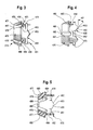
- Verification pin 500 is a unitary structure made of polymeric material such as polypthalamide (PPA). It includes a longitudinally elongate barrel portion 502 having a solid rounded free end 504 which aids in its insertion into the bore 333 of body 312. A latching portion is defined by a pair of latching body portions 506. These latching bodies 506 releasably secure the pin 500 to the fitting 310. Actuation finger portions 508 provide mechanism for releasing the latching body portions 506 for removal of the pin 500 from fitting 312.
- PPA polypthalamide
- Barrel portion 502 includes an outer cylindrical sealing surface 510 that is sized to about the same diameter as the outer cylindrical sealing surface 324 of rigid tube 320. With verification pin 500 inserted into throughbore 333 through entrance opening at planar wall surface 334, as illustrated in Fig 10 , the barrel portion 502 has an axial length to extend into outer spacer 318. Barrel portion 502 is piloted in cylindrical surface 347 of tube receiving portion of connector body 312. The barrel portion 502 extends through the seal Chamber portion through the elements of seal pack 316. The O-ring seals 360 and 362 are compressed between outer cylindrical sealing surface 510 of barrel portion 502 and cylindrical sealing surface 352 to provide a fluid tight seal. The rounded free end 504 of barrel portion 502 is piloted in the internal bore surface 357 of outer spacer 318.
- Each latching body portion 506 is integrally connected to barrel portion 502 by an axial extending beam portion 512 extending from the barrel portion 502 at an end opposite the free end 504.
- the beam portions 512 define a generally "V" shaped Space 514 which, on application of radial inward force to actuation Anger portions 508 permit radial deflection of the latching body portions 506 toward each other.
- the latching body portions 506 each have an arcuate cylindrical surface 516 formed on a diameter slightly smaller man the diameter of inner cylindrical surface 463 of ring 456 of retainer 314. As best seen in Figures 11 and 12 , the beam portions 512 and latching body portions 506 are configured such that, in the unstressed condition of beam portions 512, the arcuate cylindrical surfaces 516 are positioned to reside within inner cylindrical surface 463 of ring 456 of tube retainer 314.
- the latching body portions 506 each include an arcuate conical surface 518 diverging from barrel portion 502 to arcuate cylindrical surface 516.
- the arcuate conical surfaces 518 normally reside within the interior ramped surfaces 488 defined by locking arms 476.
- Each latching body portion 506 is provided with a radially outwardly directed pawl 520 integrally formed at the arcuate conical surfaces 518.
- the pawls 520 are disposed one hundred eighty degrees (180°) apart and are sized and positioned to fit between adjacent locking arms 476 within a slot 466.
- Each pawl 520 includes a rearward radial abutment surface 522 that is curved to be complementary to the curved end surfaces 468 of slots 466 between adjacent locking arms 476 of tube retainer 314.
- the pawls 520 latch against axial rearward movement by abutment of radial abutment surfaces 522 against curved end surfaces 468 of slots 466 between adjacent locking arms 476.
- the outer cylindrical sealing surface 510 of barrel portion 502 is disposed in fluid tight sealing relation with the O-ring seals 360 and 362.
- Each of the pawls 520 includes forward guide surfaces 524 that forwardly converge to meet at an apex 525 and extend rearwardly from the apex 525 at an angle of forty five degrees (45°) to the longitudinal extent of pin 500, i.e. ninety degrees (90°) to each other.
- contact of the guide surfaces 524 with angled surfaces 482 of guide elements 481 results in rotation of the verification pin 506 to position pawls 520 in alignment with two slots 466 and permit the pawls to pass into the two slots 466 between the side surfaces 467 of adjacent locking arms 476.
- Release finger portions 508 extend from latching body portions 506.
- the forward end of each release finger 508 defines a stop surface 509 generally perpendicular to the longitudinal axis of the verification pin 500. It is spaced from rearward abutment surfaces 522 of pawls 520 a distance so as to reside rearward of a Protrusion 479 of tube retainer 314 when rearward abutment surfaces 522 are in abutting contact with curved end surfaces 468 of two slots 466. This relationship limits permissible forward insertion of verification pin 500 into throughbore 333. This contact determines the limit of forward movement of verification pin 500 relative to tube retainer 314.
- Each release finger portion 508 includes a planar ribbed surface 530 for radial inward manual manipulation of the finger portions, and latching body portions 506 toward each other to reduce the size of Space 514.
- a stop surface 532 limits the permissible movement of the locking body portions 506 toward each other.
- the quick connector coupling sub-assembly including connector body or fitting 312, tube retainer 314, seal pack 316 and outer spacer 318 is manufactured and assembled for later attachment to a fluid component such as illustrated in Fig. 2 .
- the verification pin 500 is axially releasably secured into throughbore 333 as shown in Figs. 11 and 12 to create the sub-assembly illustrated in Fig. 1 .
- the beam portions 512 are depressed radially inward until the pawls 520 pass through inner cylindrical surface 463 of ring 456 of tube retainer 314.
- the forward guide surfaces 524 of the two pawls 520 contact angled surfaces 482 of two of the guide elements 481 to circumferentially align the pawls 520 with two of the slots 466 between locking arms 476.
- the pawls 520 move sufficiently forward to pass beyond cylindrical ring 456, the pawls enter slots 466 between side faces 467 to place the rearward abutment surface 522 of each pawl 520 in abutting relation to a curved end surface 468 of a slot 466.
- the beam portions 512 flex radially outward to an unstressed condition with the pawls 520 captured within two slots 466 disposed one hundred eighty degrees (180°) apart.
- each latching body 506 lies within inner cylindrical surface 463 of ring 456 and arcuate conical surfaces 518 are surrounded by interior ramped surfaces 488 of locking arms 476. Stop surfaces 509 of actuation finger portions 508 abut protrusions 479.
- the outer cylindrical sealing surface 510 of barrel portion 502 of verification pin 500 is disposed in fluid tight relation to O-rings 360 and 362 of seal pack 316.
- the quick connector coupling fitting 310 with verification pin 500 releasably attached may be installed onto a test fixture to test against leakage of the seal pack 316 within seal Chamber portion.
- the threaded end 326 is screwed into a test fixture and its connection sealed by sealing washer 330.
- fluid under pressure enters the passage defined by surface 357 on outer spacer 318 through exit opening 335.
- the O-ring seals 360 and 362 are compressed in fluid tight relation between cylindrical sealing surface 352 of seal Chamber portion of connector body 312 and outer cylindrical sealing surface 510 of barrel portion 502 of verification pin 500. Any leakage from fitting body 312 will indicate the absence of, or change to, to the components of seal pack 316.
- passage 358 imparts axial forces to solid rounded free end 504 of verification pin 500 to urge it axially rearward out of the throughbore 333.
- the latching relation of the rearward abutment surfaces 522 of pawls 520 with curved end surfaces 468 of slots 466 prevents such movement and retains the verification pin 500 in position within connector body 312. Since the releasable latching connection of the verification pin 500 to the sub-assembly is with the tube retainer 314 rather than a surface on connector body 312, for example, radial annular abutment surface 344, successful pressure testing verifies the presence of the tube retainer 314 on the assemblage.
- the verification pin 500 is easily removed, and discarded.
- Actuation fingers 508 are manipulated toward each other until the pawls 520 can pass through inner cylindrical surface 463 of cylindrical ring 456 of retainer.
- the tube 320 is inserted into the throughbore 333 of connector body 312 to complete a fluid tight coupling 310.
Landscapes
- Engineering & Computer Science (AREA)
- General Engineering & Computer Science (AREA)
- Mechanical Engineering (AREA)
- Quick-Acting Or Multi-Walled Pipe Joints (AREA)
Priority Applications (1)
| Application Number | Priority Date | Filing Date | Title |
|---|---|---|---|
| PL10787942T PL2504613T3 (pl) | 2009-11-23 | 2010-11-19 | Kołek kontrolny |
Applications Claiming Priority (2)
| Application Number | Priority Date | Filing Date | Title |
|---|---|---|---|
| US26369109P | 2009-11-23 | 2009-11-23 | |
| PCT/US2010/057390 WO2011063211A1 (en) | 2009-11-23 | 2010-11-19 | Verification pin |
Publications (2)
| Publication Number | Publication Date |
|---|---|
| EP2504613A1 EP2504613A1 (en) | 2012-10-03 |
| EP2504613B1 true EP2504613B1 (en) | 2014-03-05 |
Family
ID=43598491
Family Applications (1)
| Application Number | Title | Priority Date | Filing Date |
|---|---|---|---|
| EP10787942.1A Active EP2504613B1 (en) | 2009-11-23 | 2010-11-19 | Verification pin |
Country Status (8)
| Country | Link |
|---|---|
| US (1) | US20110121559A1 (enExample) |
| EP (1) | EP2504613B1 (enExample) |
| JP (1) | JP5738308B2 (enExample) |
| KR (1) | KR101793301B1 (enExample) |
| CN (1) | CN102648373B (enExample) |
| ES (1) | ES2467927T3 (enExample) |
| PL (1) | PL2504613T3 (enExample) |
| WO (1) | WO2011063211A1 (enExample) |
Families Citing this family (6)
| Publication number | Priority date | Publication date | Assignee | Title |
|---|---|---|---|---|
| DE102013021678B3 (de) * | 2013-12-18 | 2015-02-05 | Hans Oetiker Ag Maschinen- Und Apparatefabrik | Verschlussstopfen für eine Schnellkupplung |
| DE102014109319A1 (de) * | 2014-07-03 | 2016-01-07 | Illinois Tool Works Inc. | Kappe für eine Schnellverbinderkupplung |
| DE102014223063A1 (de) * | 2014-11-12 | 2016-05-12 | Robert Bosch Gmbh | Verbindungsanordnung mit einem hydraulischen Verbindungselement |
| DE102020204713B4 (de) * | 2020-04-15 | 2022-07-07 | Volkswagen Aktiengesellschaft | Ladedose mit einer Verriegelungsvorrichtung für ein Elektro-Fahrzeug |
| EP3916274A1 (en) * | 2020-05-26 | 2021-12-01 | Dresser-Rand SAS | Pin locking device for a sealing component of a seal cartridge assembly and method for assembling the seal cartridge |
| CN112780771A (zh) * | 2021-03-08 | 2021-05-11 | 力源液压(苏州)有限公司 | 一种应用于液压轴向柱塞泵的密封结构及液压轴向柱塞泵 |
Family Cites Families (9)
| Publication number | Priority date | Publication date | Assignee | Title |
|---|---|---|---|---|
| US5472016A (en) | 1993-10-04 | 1995-12-05 | Itt Corporation | Quick connector stuffer pin |
| US5486025A (en) * | 1994-09-29 | 1996-01-23 | Bundy Corporation | Stuffer pin assembly for quick connector |
| FR2788832B1 (fr) * | 1999-01-26 | 2001-02-23 | Legris Sa | Dispositif de raccordement rapide d'un tube a un element rigide |
| GB9902681D0 (en) | 1999-02-05 | 1999-03-31 | Guest John D | Improvements in or relating to tube couplings |
| US6757950B2 (en) | 2002-11-15 | 2004-07-06 | Itt Manufacturing Enterprises, Inc. | Rotatable quick connector stuffer pin |
| US7472931B2 (en) * | 2004-09-13 | 2009-01-06 | Ti Group Automotive Systems, Llc | Coupling assembly for tubing and hose connections |
| US7481465B2 (en) * | 2005-09-02 | 2009-01-27 | Ti Group Automotive Systems, Llc | Quick connector for high pressure applications, assembly tool and method |
| US8939470B2 (en) * | 2007-03-20 | 2015-01-27 | Stephen H. Gunderson | Quick connector for high pressure applications |
| CN101576187A (zh) * | 2008-05-08 | 2009-11-11 | Ti集团机车系统公司 | 快速连接器、松脱工具及其方法 |
-
2010
- 2010-11-19 PL PL10787942T patent/PL2504613T3/pl unknown
- 2010-11-19 US US12/950,145 patent/US20110121559A1/en not_active Abandoned
- 2010-11-19 KR KR1020127015577A patent/KR101793301B1/ko active Active
- 2010-11-19 JP JP2012541126A patent/JP5738308B2/ja active Active
- 2010-11-19 ES ES10787942.1T patent/ES2467927T3/es active Active
- 2010-11-19 EP EP10787942.1A patent/EP2504613B1/en active Active
- 2010-11-19 WO PCT/US2010/057390 patent/WO2011063211A1/en not_active Ceased
- 2010-11-19 CN CN201080052745.2A patent/CN102648373B/zh active Active
Also Published As
| Publication number | Publication date |
|---|---|
| JP2013511688A (ja) | 2013-04-04 |
| EP2504613A1 (en) | 2012-10-03 |
| CN102648373B (zh) | 2015-07-22 |
| KR20120093376A (ko) | 2012-08-22 |
| KR101793301B1 (ko) | 2017-11-20 |
| ES2467927T3 (es) | 2014-06-13 |
| WO2011063211A1 (en) | 2011-05-26 |
| US20110121559A1 (en) | 2011-05-26 |
| CN102648373A (zh) | 2012-08-22 |
| JP5738308B2 (ja) | 2015-06-24 |
| PL2504613T3 (pl) | 2014-12-31 |
Similar Documents
| Publication | Publication Date | Title |
|---|---|---|
| US7467813B2 (en) | Quick connector | |
| EP2504613B1 (en) | Verification pin | |
| US7891380B2 (en) | Protective cap for quick connector | |
| US4948176A (en) | Swivelable quick connector assembly | |
| EP0663558B1 (en) | Quick connect tubing connector | |
| US8939470B2 (en) | Quick connector for high pressure applications | |
| KR20140092260A (ko) | 퀵 커넥터 | |
| US8240719B2 (en) | Adaptor and method for converting standard tube fitting/port to push-to-connect tube fitting/port | |
| US20030102667A1 (en) | Plug connection | |
| US12072048B2 (en) | Device for connecting a tubular element | |
| EP1518070B1 (en) | High pressure fluid quick connect | |
| EP2264278B1 (en) | Subsea hydraulic coupler | |
| EP1979663B1 (en) | Adaptor and method for converting standard tube fitting/port to push-to-connect tube fitting/port | |
| CA2439251A1 (en) | Pipe coupling | |
| US7481465B2 (en) | Quick connector for high pressure applications, assembly tool and method | |
| GB2445701A (en) | Assembly of male and female members | |
| KR102741513B1 (ko) | 신속 연결부 | |
| US20060175831A1 (en) | Fluid quick connect contamination cover |
Legal Events
| Date | Code | Title | Description |
|---|---|---|---|
| PUAI | Public reference made under article 153(3) epc to a published international application that has entered the european phase |
Free format text: ORIGINAL CODE: 0009012 |
|
| 17P | Request for examination filed |
Effective date: 20120511 |
|
| AK | Designated contracting states |
Kind code of ref document: A1 Designated state(s): AL AT BE BG CH CY CZ DE DK EE ES FI FR GB GR HR HU IE IS IT LI LT LU LV MC MK MT NL NO PL PT RO RS SE SI SK SM TR |
|
| DAX | Request for extension of the european patent (deleted) | ||
| GRAP | Despatch of communication of intention to grant a patent |
Free format text: ORIGINAL CODE: EPIDOSNIGR1 |
|
| INTG | Intention to grant announced |
Effective date: 20130923 |
|
| GRAS | Grant fee paid |
Free format text: ORIGINAL CODE: EPIDOSNIGR3 |
|
| GRAA | (expected) grant |
Free format text: ORIGINAL CODE: 0009210 |
|
| AK | Designated contracting states |
Kind code of ref document: B1 Designated state(s): AL AT BE BG CH CY CZ DE DK EE ES FI FR GB GR HR HU IE IS IT LI LT LU LV MC MK MT NL NO PL PT RO RS SE SI SK SM TR |
|
| REG | Reference to a national code |
Ref country code: GB Ref legal event code: FG4D |
|
| REG | Reference to a national code |
Ref country code: CH Ref legal event code: EP |
|
| REG | Reference to a national code |
Ref country code: AT Ref legal event code: REF Ref document number: 655130 Country of ref document: AT Kind code of ref document: T Effective date: 20140315 |
|
| REG | Reference to a national code |
Ref country code: IE Ref legal event code: FG4D |
|
| REG | Reference to a national code |
Ref country code: DE Ref legal event code: R096 Ref document number: 602010014063 Country of ref document: DE Effective date: 20140417 |
|
| REG | Reference to a national code |
Ref country code: ES Ref legal event code: FG2A Ref document number: 2467927 Country of ref document: ES Kind code of ref document: T3 Effective date: 20140613 |
|
| REG | Reference to a national code |
Ref country code: SE Ref legal event code: TRGR |
|
| REG | Reference to a national code |
Ref country code: AT Ref legal event code: MK05 Ref document number: 655130 Country of ref document: AT Kind code of ref document: T Effective date: 20140305 |
|
| REG | Reference to a national code |
Ref country code: NL Ref legal event code: VDEP Effective date: 20140305 |
|
| PG25 | Lapsed in a contracting state [announced via postgrant information from national office to epo] |
Ref country code: NO Free format text: LAPSE BECAUSE OF FAILURE TO SUBMIT A TRANSLATION OF THE DESCRIPTION OR TO PAY THE FEE WITHIN THE PRESCRIBED TIME-LIMIT Effective date: 20140605 Ref country code: LT Free format text: LAPSE BECAUSE OF FAILURE TO SUBMIT A TRANSLATION OF THE DESCRIPTION OR TO PAY THE FEE WITHIN THE PRESCRIBED TIME-LIMIT Effective date: 20140305 |
|
| REG | Reference to a national code |
Ref country code: LT Ref legal event code: MG4D |
|
| PG25 | Lapsed in a contracting state [announced via postgrant information from national office to epo] |
Ref country code: CY Free format text: LAPSE BECAUSE OF FAILURE TO SUBMIT A TRANSLATION OF THE DESCRIPTION OR TO PAY THE FEE WITHIN THE PRESCRIBED TIME-LIMIT Effective date: 20140305 Ref country code: FI Free format text: LAPSE BECAUSE OF FAILURE TO SUBMIT A TRANSLATION OF THE DESCRIPTION OR TO PAY THE FEE WITHIN THE PRESCRIBED TIME-LIMIT Effective date: 20140305 Ref country code: AT Free format text: LAPSE BECAUSE OF FAILURE TO SUBMIT A TRANSLATION OF THE DESCRIPTION OR TO PAY THE FEE WITHIN THE PRESCRIBED TIME-LIMIT Effective date: 20140305 |
|
| PG25 | Lapsed in a contracting state [announced via postgrant information from national office to epo] |
Ref country code: RS Free format text: LAPSE BECAUSE OF FAILURE TO SUBMIT A TRANSLATION OF THE DESCRIPTION OR TO PAY THE FEE WITHIN THE PRESCRIBED TIME-LIMIT Effective date: 20140305 Ref country code: LV Free format text: LAPSE BECAUSE OF FAILURE TO SUBMIT A TRANSLATION OF THE DESCRIPTION OR TO PAY THE FEE WITHIN THE PRESCRIBED TIME-LIMIT Effective date: 20140305 Ref country code: HR Free format text: LAPSE BECAUSE OF FAILURE TO SUBMIT A TRANSLATION OF THE DESCRIPTION OR TO PAY THE FEE WITHIN THE PRESCRIBED TIME-LIMIT Effective date: 20140305 |
|
| PG25 | Lapsed in a contracting state [announced via postgrant information from national office to epo] |
Ref country code: RO Free format text: LAPSE BECAUSE OF FAILURE TO SUBMIT A TRANSLATION OF THE DESCRIPTION OR TO PAY THE FEE WITHIN THE PRESCRIBED TIME-LIMIT Effective date: 20140305 Ref country code: NL Free format text: LAPSE BECAUSE OF FAILURE TO SUBMIT A TRANSLATION OF THE DESCRIPTION OR TO PAY THE FEE WITHIN THE PRESCRIBED TIME-LIMIT Effective date: 20140305 Ref country code: EE Free format text: LAPSE BECAUSE OF FAILURE TO SUBMIT A TRANSLATION OF THE DESCRIPTION OR TO PAY THE FEE WITHIN THE PRESCRIBED TIME-LIMIT Effective date: 20140305 Ref country code: IS Free format text: LAPSE BECAUSE OF FAILURE TO SUBMIT A TRANSLATION OF THE DESCRIPTION OR TO PAY THE FEE WITHIN THE PRESCRIBED TIME-LIMIT Effective date: 20140705 Ref country code: BE Free format text: LAPSE BECAUSE OF FAILURE TO SUBMIT A TRANSLATION OF THE DESCRIPTION OR TO PAY THE FEE WITHIN THE PRESCRIBED TIME-LIMIT Effective date: 20140305 Ref country code: BG Free format text: LAPSE BECAUSE OF FAILURE TO SUBMIT A TRANSLATION OF THE DESCRIPTION OR TO PAY THE FEE WITHIN THE PRESCRIBED TIME-LIMIT Effective date: 20140605 |
|
| PG25 | Lapsed in a contracting state [announced via postgrant information from national office to epo] |
Ref country code: SK Free format text: LAPSE BECAUSE OF FAILURE TO SUBMIT A TRANSLATION OF THE DESCRIPTION OR TO PAY THE FEE WITHIN THE PRESCRIBED TIME-LIMIT Effective date: 20140305 |
|
| REG | Reference to a national code |
Ref country code: DE Ref legal event code: R097 Ref document number: 602010014063 Country of ref document: DE |
|
| PG25 | Lapsed in a contracting state [announced via postgrant information from national office to epo] |
Ref country code: PT Free format text: LAPSE BECAUSE OF FAILURE TO SUBMIT A TRANSLATION OF THE DESCRIPTION OR TO PAY THE FEE WITHIN THE PRESCRIBED TIME-LIMIT Effective date: 20140707 |
|
| REG | Reference to a national code |
Ref country code: PL Ref legal event code: T3 |
|
| PLBE | No opposition filed within time limit |
Free format text: ORIGINAL CODE: 0009261 |
|
| STAA | Information on the status of an ep patent application or granted ep patent |
Free format text: STATUS: NO OPPOSITION FILED WITHIN TIME LIMIT |
|
| PG25 | Lapsed in a contracting state [announced via postgrant information from national office to epo] |
Ref country code: DK Free format text: LAPSE BECAUSE OF FAILURE TO SUBMIT A TRANSLATION OF THE DESCRIPTION OR TO PAY THE FEE WITHIN THE PRESCRIBED TIME-LIMIT Effective date: 20140305 |
|
| 26N | No opposition filed |
Effective date: 20141208 |
|
| REG | Reference to a national code |
Ref country code: DE Ref legal event code: R097 Ref document number: 602010014063 Country of ref document: DE Effective date: 20141208 |
|
| PG25 | Lapsed in a contracting state [announced via postgrant information from national office to epo] |
Ref country code: SI Free format text: LAPSE BECAUSE OF FAILURE TO SUBMIT A TRANSLATION OF THE DESCRIPTION OR TO PAY THE FEE WITHIN THE PRESCRIBED TIME-LIMIT Effective date: 20140305 |
|
| PG25 | Lapsed in a contracting state [announced via postgrant information from national office to epo] |
Ref country code: MC Free format text: LAPSE BECAUSE OF FAILURE TO SUBMIT A TRANSLATION OF THE DESCRIPTION OR TO PAY THE FEE WITHIN THE PRESCRIBED TIME-LIMIT Effective date: 20140305 Ref country code: LU Free format text: LAPSE BECAUSE OF FAILURE TO SUBMIT A TRANSLATION OF THE DESCRIPTION OR TO PAY THE FEE WITHIN THE PRESCRIBED TIME-LIMIT Effective date: 20141119 |
|
| REG | Reference to a national code |
Ref country code: CH Ref legal event code: PL |
|
| GBPC | Gb: european patent ceased through non-payment of renewal fee |
Effective date: 20141119 |
|
| PG25 | Lapsed in a contracting state [announced via postgrant information from national office to epo] |
Ref country code: LI Free format text: LAPSE BECAUSE OF NON-PAYMENT OF DUE FEES Effective date: 20141130 Ref country code: CH Free format text: LAPSE BECAUSE OF NON-PAYMENT OF DUE FEES Effective date: 20141130 |
|
| REG | Reference to a national code |
Ref country code: IE Ref legal event code: MM4A |
|
| PG25 | Lapsed in a contracting state [announced via postgrant information from national office to epo] |
Ref country code: IE Free format text: LAPSE BECAUSE OF NON-PAYMENT OF DUE FEES Effective date: 20141119 Ref country code: GB Free format text: LAPSE BECAUSE OF NON-PAYMENT OF DUE FEES Effective date: 20141119 |
|
| REG | Reference to a national code |
Ref country code: FR Ref legal event code: PLFP Year of fee payment: 6 |
|
| PG25 | Lapsed in a contracting state [announced via postgrant information from national office to epo] |
Ref country code: SM Free format text: LAPSE BECAUSE OF FAILURE TO SUBMIT A TRANSLATION OF THE DESCRIPTION OR TO PAY THE FEE WITHIN THE PRESCRIBED TIME-LIMIT Effective date: 20140305 |
|
| PG25 | Lapsed in a contracting state [announced via postgrant information from national office to epo] |
Ref country code: GR Free format text: LAPSE BECAUSE OF FAILURE TO SUBMIT A TRANSLATION OF THE DESCRIPTION OR TO PAY THE FEE WITHIN THE PRESCRIBED TIME-LIMIT Effective date: 20140606 |
|
| PG25 | Lapsed in a contracting state [announced via postgrant information from national office to epo] |
Ref country code: HU Free format text: LAPSE BECAUSE OF FAILURE TO SUBMIT A TRANSLATION OF THE DESCRIPTION OR TO PAY THE FEE WITHIN THE PRESCRIBED TIME-LIMIT; INVALID AB INITIO Effective date: 20101119 Ref country code: TR Free format text: LAPSE BECAUSE OF FAILURE TO SUBMIT A TRANSLATION OF THE DESCRIPTION OR TO PAY THE FEE WITHIN THE PRESCRIBED TIME-LIMIT Effective date: 20140305 Ref country code: MT Free format text: LAPSE BECAUSE OF FAILURE TO SUBMIT A TRANSLATION OF THE DESCRIPTION OR TO PAY THE FEE WITHIN THE PRESCRIBED TIME-LIMIT Effective date: 20140305 |
|
| REG | Reference to a national code |
Ref country code: FR Ref legal event code: PLFP Year of fee payment: 7 |
|
| REG | Reference to a national code |
Ref country code: FR Ref legal event code: PLFP Year of fee payment: 8 |
|
| PG25 | Lapsed in a contracting state [announced via postgrant information from national office to epo] |
Ref country code: MK Free format text: LAPSE BECAUSE OF FAILURE TO SUBMIT A TRANSLATION OF THE DESCRIPTION OR TO PAY THE FEE WITHIN THE PRESCRIBED TIME-LIMIT Effective date: 20140305 |
|
| PG25 | Lapsed in a contracting state [announced via postgrant information from national office to epo] |
Ref country code: AL Free format text: LAPSE BECAUSE OF FAILURE TO SUBMIT A TRANSLATION OF THE DESCRIPTION OR TO PAY THE FEE WITHIN THE PRESCRIBED TIME-LIMIT Effective date: 20140305 |
|
| PGFP | Annual fee paid to national office [announced via postgrant information from national office to epo] |
Ref country code: CZ Payment date: 20191105 Year of fee payment: 10 Ref country code: SE Payment date: 20191128 Year of fee payment: 10 |
|
| PGFP | Annual fee paid to national office [announced via postgrant information from national office to epo] |
Ref country code: ES Payment date: 20191216 Year of fee payment: 10 Ref country code: PL Payment date: 20191112 Year of fee payment: 10 Ref country code: IT Payment date: 20191120 Year of fee payment: 10 |
|
| REG | Reference to a national code |
Ref country code: SE Ref legal event code: EUG |
|
| PG25 | Lapsed in a contracting state [announced via postgrant information from national office to epo] |
Ref country code: CZ Free format text: LAPSE BECAUSE OF NON-PAYMENT OF DUE FEES Effective date: 20201119 |
|
| PG25 | Lapsed in a contracting state [announced via postgrant information from national office to epo] |
Ref country code: SE Free format text: LAPSE BECAUSE OF NON-PAYMENT OF DUE FEES Effective date: 20201120 |
|
| PG25 | Lapsed in a contracting state [announced via postgrant information from national office to epo] |
Ref country code: IT Free format text: LAPSE BECAUSE OF NON-PAYMENT OF DUE FEES Effective date: 20201119 |
|
| REG | Reference to a national code |
Ref country code: ES Ref legal event code: FD2A Effective date: 20220202 |
|
| PG25 | Lapsed in a contracting state [announced via postgrant information from national office to epo] |
Ref country code: ES Free format text: LAPSE BECAUSE OF NON-PAYMENT OF DUE FEES Effective date: 20201120 |
|
| PG25 | Lapsed in a contracting state [announced via postgrant information from national office to epo] |
Ref country code: PL Free format text: LAPSE BECAUSE OF NON-PAYMENT OF DUE FEES Effective date: 20201119 |
|
| P01 | Opt-out of the competence of the unified patent court (upc) registered |
Effective date: 20230524 |
|
| PGFP | Annual fee paid to national office [announced via postgrant information from national office to epo] |
Ref country code: DE Payment date: 20251118 Year of fee payment: 16 |
|
| PGFP | Annual fee paid to national office [announced via postgrant information from national office to epo] |
Ref country code: FR Payment date: 20251125 Year of fee payment: 16 |