EP2503584A1 - Melt resistant insert and overload protection device - Google Patents
Melt resistant insert and overload protection device Download PDFInfo
- Publication number
- EP2503584A1 EP2503584A1 EP20120155736 EP12155736A EP2503584A1 EP 2503584 A1 EP2503584 A1 EP 2503584A1 EP 20120155736 EP20120155736 EP 20120155736 EP 12155736 A EP12155736 A EP 12155736A EP 2503584 A1 EP2503584 A1 EP 2503584A1
- Authority
- EP
- European Patent Office
- Prior art keywords
- ceramic body
- fuse
- sand
- volume
- solidified sand
- Prior art date
- Legal status (The legal status is an assumption and is not a legal conclusion. Google has not performed a legal analysis and makes no representation as to the accuracy of the status listed.)
- Withdrawn
Links
- 239000000919 ceramic Substances 0.000 claims abstract description 80
- 239000004576 sand Substances 0.000 claims abstract description 53
- 239000004065 semiconductor Substances 0.000 claims abstract description 4
- 239000013013 elastic material Substances 0.000 claims description 5
- 238000001125 extrusion Methods 0.000 claims description 5
- 239000000203 mixture Substances 0.000 claims description 4
- 230000001681 protective effect Effects 0.000 claims 1
- VYPSYNLAJGMNEJ-UHFFFAOYSA-N Silicium dioxide Chemical compound O=[Si]=O VYPSYNLAJGMNEJ-UHFFFAOYSA-N 0.000 description 51
- 239000004020 conductor Substances 0.000 description 8
- 239000006004 Quartz sand Substances 0.000 description 6
- 238000004519 manufacturing process Methods 0.000 description 5
- PNEYBMLMFCGWSK-UHFFFAOYSA-N aluminium oxide Inorganic materials [O-2].[O-2].[O-2].[Al+3].[Al+3] PNEYBMLMFCGWSK-UHFFFAOYSA-N 0.000 description 4
- 239000000155 melt Substances 0.000 description 4
- 238000000034 method Methods 0.000 description 4
- 229910010293 ceramic material Inorganic materials 0.000 description 3
- 239000007789 gas Substances 0.000 description 3
- 238000002844 melting Methods 0.000 description 3
- 230000008018 melting Effects 0.000 description 3
- IJGRMHOSHXDMSA-UHFFFAOYSA-N Atomic nitrogen Chemical compound N#N IJGRMHOSHXDMSA-UHFFFAOYSA-N 0.000 description 2
- 239000003795 chemical substances by application Substances 0.000 description 2
- 239000000463 material Substances 0.000 description 2
- 239000002184 metal Substances 0.000 description 2
- 238000000465 moulding Methods 0.000 description 2
- 230000004308 accommodation Effects 0.000 description 1
- 230000002411 adverse Effects 0.000 description 1
- 230000015572 biosynthetic process Effects 0.000 description 1
- 238000006243 chemical reaction Methods 0.000 description 1
- 239000007795 chemical reaction product Substances 0.000 description 1
- 238000013016 damping Methods 0.000 description 1
- 230000001419 dependent effect Effects 0.000 description 1
- 238000005553 drilling Methods 0.000 description 1
- 230000000694 effects Effects 0.000 description 1
- 230000017525 heat dissipation Effects 0.000 description 1
- 239000011261 inert gas Substances 0.000 description 1
- 239000012212 insulator Substances 0.000 description 1
- 239000007788 liquid Substances 0.000 description 1
- 229910052757 nitrogen Inorganic materials 0.000 description 1
- 229910052756 noble gas Inorganic materials 0.000 description 1
- 150000002835 noble gases Chemical class 0.000 description 1
- 239000002244 precipitate Substances 0.000 description 1
- 239000000377 silicon dioxide Substances 0.000 description 1
- 230000008961 swelling Effects 0.000 description 1
- 230000001960 triggered effect Effects 0.000 description 1
Images

Classifications
-
- H—ELECTRICITY
- H01—ELECTRIC ELEMENTS
- H01H—ELECTRIC SWITCHES; RELAYS; SELECTORS; EMERGENCY PROTECTIVE DEVICES
- H01H85/00—Protective devices in which the current flows through a part of fusible material and this current is interrupted by displacement of the fusible material when this current becomes excessive
- H01H85/0078—Security-related arrangements
- H01H85/0082—Security-related arrangements preventing explosion of the cartridge
-
- H—ELECTRICITY
- H01—ELECTRIC ELEMENTS
- H01H—ELECTRIC SWITCHES; RELAYS; SELECTORS; EMERGENCY PROTECTIVE DEVICES
- H01H85/00—Protective devices in which the current flows through a part of fusible material and this current is interrupted by displacement of the fusible material when this current becomes excessive
- H01H85/02—Details
- H01H85/43—Means for exhausting or absorbing gases liberated by fusing arc, or for ventilating excess pressure generated by heating
-
- H—ELECTRICITY
- H01—ELECTRIC ELEMENTS
- H01H—ELECTRIC SWITCHES; RELAYS; SELECTORS; EMERGENCY PROTECTIVE DEVICES
- H01H85/00—Protective devices in which the current flows through a part of fusible material and this current is interrupted by displacement of the fusible material when this current becomes excessive
- H01H85/02—Details
- H01H85/04—Fuses, i.e. expendable parts of the protective device, e.g. cartridges
- H01H85/05—Component parts thereof
- H01H85/165—Casings
- H01H85/175—Casings characterised by the casing shape or form
-
- H—ELECTRICITY
- H01—ELECTRIC ELEMENTS
- H01H—ELECTRIC SWITCHES; RELAYS; SELECTORS; EMERGENCY PROTECTIVE DEVICES
- H01H85/00—Protective devices in which the current flows through a part of fusible material and this current is interrupted by displacement of the fusible material when this current becomes excessive
- H01H85/02—Details
- H01H85/04—Fuses, i.e. expendable parts of the protective device, e.g. cartridges
- H01H85/05—Component parts thereof
- H01H85/18—Casing fillings, e.g. powder
Definitions
- the invention relates to a fuse insert - especially for semiconductor protection fuses - which has a filled with solidified sand ceramic body. Furthermore, the invention relates to an overcurrent protection device with such a fuse link.
- a fuse is an overcurrent protection device that interrupts the circuit by melting one or more fusible links when the current exceeds a certain level over a certain period of time. It consists of an insulating body, which has two electrical connections, which are interconnected in the interior of the insulating body by a fusible link. The fusible conductor is heated by the current flowing through it and melts when the relevant nominal current of the fuse is clearly exceeded for a certain period of time. Due to its good insulating effect is used as the material for the insulating body mostly ceramic.
- the melt conductor is surrounded by quartz sand.
- a ceramic body forms the housing of the fuse link, in which the solidified sand, the electrical connections and the fusible conductor are accommodated or held.
- the quartz sand acts as an arc extinguishing agent: the rated current of the fuse is clearly exceeded - for example, due to a short circuit - so this leads to a response of the fuse, in the course of which the fusible element melts first and then evaporated due to the high temperature development. This creates an electrically conductive plasma, via which the current flow between the electrical connections is initially maintained - it arises an arc.
- the fuse protection insert according to the invention in particular for semiconductor protection fuses, has a ceramic body filled with solidified sand.
- the ceramic body in turn has a volume reservoir, which is designed such that upon an increase in internal pressure in the ceramic body due to a temperature expansion of the solidified sand through the volume reservoir, an additional volume is released in the ceramic body to expand the solidified sand.
- the ceramic body and the solidified sand generally have different coefficients of thermal expansion, ie, the solidified sand expands at a temperature increase more than the ceramic body surrounding the solidified sand, which at a temperature increase to an increase of the internal pressure in the ceramic body and thus to stresses in the ceramic body leads.
- the internal pressure arising in the ceramic body can be limited to a tolerable value become. In this way, damage to the ceramic body by stress cracks, caused by the different degrees of thermal expansion solidified sand and ceramic body, avoided. The robustness of the fuse insert is thereby significantly improved.
- the ceramic body can be used for the production of the ceramic body to a ceramic with a lower alumina content.
- a ceramic is cheaper to produce and, on the other hand, simpler to process, so that the manufacturing costs of the fuse-linkage insert can be significantly reduced as a result.
- a simpler ceramic can thus be used for the same power; special designs for problematic operating conditions, which even high-quality ceramics are not sufficient for, can be realized by introducing an additional body into the solidified sand.
- the volume reservoir is formed on an inner wall of the ceramic body.
- the ceramic body is a housing of the fuse insert, the interior of which is designed to receive the solidified sand.
- the arrangement of the volume reservoir on an inner wall of the ceramic body - and thus in the immediate vicinity of the solidified sand - ensures that the additional volume released by the volume reservoir is directly available for the expansion of the solidified sand.
- the volume reservoir is separated from the solidified sand by a web of the ceramic body.
- the web is designed such that it breaks upon reaching a predefined internal pressure, whereby the additional volume for the expansion of the solidified sand in the ceramic body is released.
- the web has a comparatively thin wall thickness, which acts as a "predetermined breaking point" in the event of a pressure increase inside the ceramic body - i. breaks down - so that the previously sealed off from the solidified sand volume reservoir is released and is available for further expansion of the consolidated sand.
- the ceramic body may also have a plurality of volume reservoirs divided by webs.
- the webs may have different wall thicknesses, so that they do not break at the same time, but one after another at a swelling of the internal pressure. In this way, the additional volume for further expansion of the solidified sand may be cascaded, i. in several portions, to be released.
- the volume reservoir is filled with an air or gas mixture.
- air represents a simple and cost-effective way to improve the fuse link.
- a gas mixture - for example, inert that is, inert gases such as nitrogen or noble gases - can be used.
- the volume reservoir is filled with unconsolidated sand.
- the additional volume provided by the volume reservoir can be limited to a low value without adversely affecting the accuracy of the triggering of the fuse link insert.
- a certain manufacturing accuracy of the ceramic body in terms of its geometry and its wall thickness is required.
- the conditional by the manufacturing process minimum wall thickness in turn requires a minimum size of the volume reservoir, which difficult with only a small additional volume realize is.
- volume reservoir with unconsolidated sand, however, makes it possible to provide only a small additional volume for further expansion of the solidified sand, even in the case of the geometrically determined minimum size of the volume reservoir described above, wherein the threshold value of the internal pressure, from which the additional volume is to be available, can be predetermined with relatively good accuracy.
- the volume reservoir is filled with an elastic material.
- filling the volume reservoir with an elastic material is a convenient way to provide only a small additional volume for further expansion of the consolidated sand.
- the filling with elastic material has the further advantage that no voids are formed in the solidified sand in the provision of the additional volume. Instead, the further expansion of the solidified sand is achieved at almost constant internal pressure by compressing the elastic body.
- the fuse insert of the ceramic body can be produced by extrusion.
- An extrusion process is a simple and extremely cost-effective way of producing the ceramic body, which is particularly suitable for the processing of simple ceramic materials.
- High quality ceramics, especially those with a high alumina content, are only partially suitable or even completely unsuitable for processing by means of an extrusion process.
- the overcurrent protection device according to the invention has at least one fuse link according to the above statements. With regard to the advantages of such an overcurrent protection device Reference is made to the preceding remarks on the advantages of the fuse protection insert according to the invention.
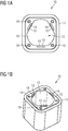
- FIG. 1A shows a plan view
- FIG. 1B the fuse element 10 is shown in a perspective view.
- the fuse link 10 has a ceramic body 11 in the form of a tubular hollow body, at both ends of which is in each case an opening 15.
- the inner region of the ceramic body 11 surrounded by the tubular hollow body essentially serves as a receiving space 12 for receiving solidified sand (not shown), which serves as extinguishing agent for extinguishing a fire fuse insert 10 that is triggered Arc serves.
- a contact element (not shown) can be arranged in each case, via which the fuse link 10 can be contacted with an electrical line to be protected.
- a respective cover plate (not shown, which can be fastened to the ceramic body via a plurality of bores 19 formed in the ceramic body 11, the respective contact element is centered and held relative to the ceramic body 11.
- the two cover plates serve the two openings 15 A so-called fusible conductor (not shown), which connects the two contact elements in the interior of the fusible link insert in an electrically conductive manner, is generally arranged in the receiving space 12.
- the fusible conductor is solidified in the fully assembled state Sand, for example quartz sand, surrounded, but not shown for reasons of clarity in the figures.
- the ceramic body 11 has a volume reservoir in the form of a plurality of chambers 14, which are formed in the wall of the ceramic body 11 and each separated by a web 13 of the solidified sand.
- the trapped by the chambers 14 volume - which may be filled, for example, with an air or gas mixture, with unconsolidated sand or with an elastic material - released. Since the solidified sand can now expand into this volume, the internal pressure drops back to a value below the threshold value. With a correct choice of the threshold value, damage to the ceramic body can thus be avoided.
- FIGS. 2A and 2B a second embodiment of the fuse fuse according to the invention is shown in two perspective views.
- the fuse link 10 in turn has a ceramic body 11, which is formed in this case as a hollow cylinder.
- the ceramic body 11 of the second embodiment corresponds to the ceramic body 11 of the in terms of the technical structure and its function Figures 1A and 1B illustrated first embodiment.
- FIG. 2B shows the ceramic body in a semi-transparent representation. It is clear that the chambers 14 and the webs 13 extend continuously over the entire length of the hollow cylindrical ceramic body 11. Since the ceramic body 11 otherwise has no undercuts, it can - if the ceramic material is suitable for this purpose - be prepared as an extruded part or by extrusion. Both original molding process is common that the material to be molded for the purpose of molding by means of a stamp or the like is pressed through a die. Both manufacturing methods are characterized by extremely low marginal costs and are particularly suitable for high volumes.
- hollow cylinder and other hollow shapes for the design of the ceramic body 11, for example, hollow cuboid or hollow prisms are used.
Landscapes
- Engineering & Computer Science (AREA)
- Computer Security & Cryptography (AREA)
- Fuses (AREA)
Abstract
Der erfindungsgemäße Schmelzsicherungseinsatz, insbesondere für Halbleiter-Schutz-Sicherungen, weist einen mit verfestigtem Sand gefüllten Keramikkörper auf. Der Keramikkörper weist seinerseits ein Volumenreservoir auf, welches derart ausgebildet ist, dass bei einer Erhöhung eines Innendrucks in dem Keramikkörper aufgrund einer Temperaturausdehnung des verfestigten Sandes durch das Volumenreservoir ein zusätzliches Volumen in dem Keramikkörper zur Ausdehnung des verfestigten Sandes freigesetzt wird. Beschädigung des Keramikkörpers (11) durch Spannungsrisse, hervorgerufen durch die unterschiedlich starke Temperaturausdehnung des verfestigten Sandes und des Keramikkörpers (11) infolge einer Temperaturerhöhung und dem damit verbundenen Anstieg des Innendrucks in dem Keramikkörper (11), können hierdurch vermieden bzw. begrenzt werden. Die Robustheit des Schmelzsicherungseinsatzes (10) wird dadurch deutlich verbessert.The fuse insert according to the invention, in particular for semiconductor protection fuses, has a ceramic body filled with solidified sand. The ceramic body in turn has a volume reservoir which is designed such that when an internal pressure in the ceramic body increases due to temperature expansion of the solidified sand through the volume reservoir, an additional volume is released in the ceramic body for expansion of the solidified sand. Damage to the ceramic body (11) due to stress cracks caused by the different degrees of thermal expansion of the solidified sand and the ceramic body (11) as a result of an increase in temperature and the associated increase in the internal pressure in the ceramic body (11) can be avoided or limited. The robustness of the fuse insert (10) is thereby significantly improved.
Description
Die Erfindung betrifft einen Schmelzsicherungseinsatz - insbesondere für Halbleiter-Schutz-Sicherungen - welcher einen mit verfestigtem Sand gefüllten Keramikkörper aufweist. Ferner betrifft die Erfindung eine Überstrom-Schutzeinrichtung mit einem derartigen Schmelzsicherungseinsatz.The invention relates to a fuse insert - especially for semiconductor protection fuses - which has a filled with solidified sand ceramic body. Furthermore, the invention relates to an overcurrent protection device with such a fuse link.
Eine Schmelzsicherung ist eine Überstromschutzeinrichtung, die durch das Abschmelzen eines oder mehrerer Schmelzleiter den Stromkreis unterbricht, wenn die Stromstärke einen bestimmten Wert über eine bestimmte Zeitdauer hinweg überschreitet. Sie besteht aus einem isolierenden Körper, welcher zwei elektrische Anschlüsse aufweist, die im Inneren des isolierenden Körpers durch einen Schmelzleiter miteinander verbunden sind. Der Schmelzleiter wird durch den ihn durchfließenden Strom erwärmt und schmilzt, wenn der maßgebliche Nennstrom der Sicherung für eine bestimmte Zeit deutlich überschritten wird. Aufgrund seiner guten Isolationswirkung wird als Material für den isolierenden Körper zumeist Keramik verwendet.A fuse is an overcurrent protection device that interrupts the circuit by melting one or more fusible links when the current exceeds a certain level over a certain period of time. It consists of an insulating body, which has two electrical connections, which are interconnected in the interior of the insulating body by a fusible link. The fusible conductor is heated by the current flowing through it and melts when the relevant nominal current of the fuse is clearly exceeded for a certain period of time. Due to its good insulating effect is used as the material for the insulating body mostly ceramic.
Bei einem sandverfestigten Schmelzsicherungseinsatz ist der Schmelzleiter von Quarzsand umgeben. Ein Keramikkörper bildet das Gehäuse des Sicherungseinsatzes, in dem der verfestigte Sand, die elektrischen Anschlüsse sowie der Schmelzleiter aufgenommen bzw. gehaltert sind. Der Quarzsand fungiert dabei als Lichtbogenlöschmittel: wird der Nennstrom der Schmelzsicherung deutlich überschrittenen - beispielsweise aufgrund eines Kurzschlusses - so führt dies zu einem Ansprechen der Schmelzsicherung, in dessen Verlauf der Schmelzleiter zunächst schmilzt und anschließend aufgrund der hohen Temperaturentwicklung verdampft. Dabei entsteht ein elektrisch leitendes Plasma, über das der Stromfluss zwischen den elektrischen Anschlüssen zunächst aufrecht erhalten wird - es entsteht ein Lichtbogen. Indem sich der Metalldampf des verdampften Schmelzleiters auf der Oberfläche der Quarzsand-Körner niederschlägt, wird der Lichtbogen wiederum abgekühlt. In der Folge steigt der Widerstand im Inneren des Sicherungseinsatzes derart an, dass der Lichtbogen endgültig verlischt. Die durch die Schmelzsicherung zu schützende Leitung ist damit unterbrochen.In a sand-strengthened fuse link, the melt conductor is surrounded by quartz sand. A ceramic body forms the housing of the fuse link, in which the solidified sand, the electrical connections and the fusible conductor are accommodated or held. The quartz sand acts as an arc extinguishing agent: the rated current of the fuse is clearly exceeded - for example, due to a short circuit - so this leads to a response of the fuse, in the course of which the fusible element melts first and then evaporated due to the high temperature development. This creates an electrically conductive plasma, via which the current flow between the electrical connections is initially maintained - it arises an arc. As the metal vapor of the vaporized fusible conductor precipitates on the surface of the silica sand grains, the arc is again cooled. As a result, the resistance in the interior of the fuse link increases in such a way that the arc finally disappears. The line to be protected by the fuse is thus interrupted.
Bei sandverfestigten Schmelzsicherungseinsätzen mit großem Sandvolumen kommt es aufgrund der unterschiedlichen Temperaturausdehnungskoeffizienten des Quarzsandes einerseits und des Keramikkörpers andererseits zu Spannungen im Keramikkörper, welche letztendlich bis zum Bruch des Keramikkörpers führen können. Am Markt erhältliche Schmelzsicherungseinsätze begegnen dieser Problematik mit dem Einsatz spezieller, hochwertiger Keramiken, welche sich beispielsweise durch einen höheren Aluminiumoxidgehalt auszeichnen. Derartige Keramiken weisen neben einer höheren Festigkeit auch noch einen größeren Temperaturausdehnungskoeffizienten auf als vergleichbare Keramiken mit einem geringeren Aluminiumoxidgehalt. Beide Eigenschaften - die höhere Festigkeit und der höhere Temperaturausdehnungskoeffizient - wirken dem Problem einer Beschädigung des Keramikkörpers entgegen. Jedoch sind die hierfür in Frage kommenden Keramikwerkstoffe aufgrund ihrer besonderen Qualitätseigenschaften relativ teuer.In sand-strengthened safety fuselage inserts with a large volume of sand, due to the different coefficients of thermal expansion of the quartz sand on the one hand and the ceramic body on the other hand tensions in the ceramic body, which can ultimately lead to breakage of the ceramic body. Available on the market fuse inserts meet this problem with the use of special, high-quality ceramics, which are characterized for example by a higher alumina content. Such ceramics have not only a higher strength but also a larger coefficient of thermal expansion than comparable ceramics with a lower alumina content. Both properties - the higher strength and the higher coefficient of thermal expansion - counteract the problem of damage to the ceramic body. However, the ceramic materials in question are relatively expensive due to their special quality properties.
Zur Reduzierung der Spannungen im Keramikkörper aufgrund der Temperaturausdehnung des verfestigten Sandes werden ferner Schmelzsicherungseinsätze angeboten, bei denen entlang des Inneren Umfangs des Keramikkörpers ein dämpfendes Element zwischen dem Keramikkörper und dem verfestigten Sand angeordnet ist. Diese Anordnung hat jedoch den Nachteil, dass die Wärmeabfuhr des Schmelzsicherungseinsatzes und damit das Auslöse- und Abschaltverhalten des Schmelzsicherungseinsatzes deutlich verschlechtert werden.To reduce the stresses in the ceramic body due to the temperature expansion of the solidified sand fusible inserts are further provided in which along the inner circumference of the ceramic body, a damping element between the ceramic body and the solidified sand is arranged. However, this arrangement has the disadvantage that the heat dissipation of the fuse link and thus the tripping and shutdown of the fuse link are significantly deteriorated.
Es ist deshalb die Aufgabe der vorliegenden Erfindung einen Schmelzsicherungseinsatz sowie eine Überstrom-Schutzeinrichtung mit einem derartigen Schmelzsicherungseinsatz bereitzustellen, welche sich durch eine verbesserte Robustheit bei gleichzeitig einfacher und kostengünstiger Herstellbarkeit auszeichnen.It is therefore an object of the present invention to provide a fuse link as well as an overcurrent protection device with such a fuse link insert, which are characterized by improved robustness and at the same time simple and cost-effective manufacturability.
Diese Aufgabe wird durch den Schmelzsicherungseinsatz sowie die Überstrom-Schutzeinrichtung gemäß den unabhängigen Ansprüchen gelöst. Vorteilhafte Ausgestaltungen sind Gegenstand der abhängigen Ansprüche.This object is achieved by the fuse link as well as the overcurrent protection device according to the independent claims. Advantageous embodiments are the subject of the dependent claims.
Der erfindungsgemäße Schmelzsicherungseinsatz, insbesondere für Halbleiter-Schutz-Sicherungen, weist einen mit verfestigtem Sand gefüllten Keramikkörper auf. Der Keramikkörper weist seinerseits ein Volumenreservoir auf, welches derart ausgebildet ist, dass bei einer Erhöhung eines Innendrucks in dem Keramikkörper aufgrund einer Temperaturausdehnung des verfestigten Sandes durch das Volumenreservoir ein zusätzliches Volumen in dem Keramikkörper zur Ausdehnung des verfestigten Sandes freigesetzt wird.The fuse protection insert according to the invention, in particular for semiconductor protection fuses, has a ceramic body filled with solidified sand. The ceramic body in turn has a volume reservoir, which is designed such that upon an increase in internal pressure in the ceramic body due to a temperature expansion of the solidified sand through the volume reservoir, an additional volume is released in the ceramic body to expand the solidified sand.
Der Keramikkörper und der verfestigte Sand weisen in der Regel unterschiedliche Temperaturausdehnungskoeffizienten auf, d.h. der verfestigte Sand dehnt sich bei einer Temperaturerhöhung stärker aus als der den verfestigten Sand umgebende Keramikkörper, was bei einer Temperaturerhöhung zu einer Erhöhung des Innendrucks im Keramikkörper und damit zu Spannungen im Keramikkörper führt. Durch die Verwendung eines in den Keramikkörper integrierten Volumenreservoirs, mit dessen Hilfe bei einer Erhöhung des Innendrucks ein zusätzliches Volumen in dem Keramikkörper bereitgestellt wird, welches zur weiteren Ausdehnung des verfestigten Sandes zur Verfügung steht, kann der in dem Keramikköper entstehende Innendruck auf einen tolerierbaren Wert begrenzt werden. Auf diese Weise wird eine Beschädigung des Keramikkörpers durch Spannungsrisse, hervorgerufen durch die unterschiedlich starke Temperaturausdehnung des verfestigten Sandes und des Keramikkörpers, vermieden. Die Robustheit des Schmelzsicherungseinsatzes wird dadurch deutlich verbessert.The ceramic body and the solidified sand generally have different coefficients of thermal expansion, ie, the solidified sand expands at a temperature increase more than the ceramic body surrounding the solidified sand, which at a temperature increase to an increase of the internal pressure in the ceramic body and thus to stresses in the ceramic body leads. By using a volume reservoir integrated into the ceramic body, with the aid of which an additional volume is provided in the ceramic body when the internal pressure is increased, which is available for further expansion of the solidified sand, the internal pressure arising in the ceramic body can be limited to a tolerable value become. In this way, damage to the ceramic body by stress cracks, caused by the different degrees of thermal expansion solidified sand and ceramic body, avoided. The robustness of the fuse insert is thereby significantly improved.
Weiterhin kann zur Herstellung des Keramikkörpers auf eine Keramik mit einem geringeren Aluminiumoxidgehalt zurückgegriffen werden. Eine derartige Keramik ist einerseits preiswerter in der Herstellung und andererseits einfacher in der Verarbeitung, so dass hierdurch auch die Herstellkosten des Schmelzsicherungseinsatzes deutlich reduziert werden können. Bei Bauformen für den Standardeinsatz kann somit bei gleicher Leistung eine einfachere Keramik verwendet werden; spezielle Bauformen für problematische Einsatzbedingungen, denen selbst hochwertige Keramiken nicht genügen, können durch Einbringen eines Zusatzkörpers in den verfestigten Sand realisiert werden.Furthermore, can be used for the production of the ceramic body to a ceramic with a lower alumina content. On the one hand, such a ceramic is cheaper to produce and, on the other hand, simpler to process, so that the manufacturing costs of the fuse-linkage insert can be significantly reduced as a result. With designs for standard use, a simpler ceramic can thus be used for the same power; special designs for problematic operating conditions, which even high-quality ceramics are not sufficient for, can be realized by introducing an additional body into the solidified sand.
In einer vorteilhaften Weiterbildung des Schmelzsicherungseinsatzes ist das Volumenreservoir an einer inneren Wandung des Keramikkörpers ausgebildet. Der Keramikkörper stellt ein Gehäuse des Schmelzsicherungseinsatzes dar, dessen Inneres zur Aufnahme des verfestigten Sandes ausgebildet ist. Durch die Anordnung des Volumenreservoirs an einer inneren Wandung des Keramikkörpers - und damit in unmittelbarer Nähe des verfestigten Sandes - wird sichergestellt, dass das durch das Volumenreservoir zusätzlich freigesetzte Volumen unmittelbar zur Ausdehnung des verfestigten Sandes zur Verfügung steht.In an advantageous development of the fuse insert, the volume reservoir is formed on an inner wall of the ceramic body. The ceramic body is a housing of the fuse insert, the interior of which is designed to receive the solidified sand. The arrangement of the volume reservoir on an inner wall of the ceramic body - and thus in the immediate vicinity of the solidified sand - ensures that the additional volume released by the volume reservoir is directly available for the expansion of the solidified sand.
In einer weiteren vorteilhaften Weiterbildung des Schmelzsicherungseinsatzes ist das Volumenreservoir durch einen Steg des Keramikkörpers von dem verfestigten Sand getrennt. Dabei ist der Steg derart ausgebildet, dass er bei Erreichen eines vordefinierten Innendrucks zerbricht, wodurch das zusätzliche Volumen zur Ausdehnung des verfestigten Sandes in dem Keramikkörper freigesetzt wird.In a further advantageous development of the fuse insert, the volume reservoir is separated from the solidified sand by a web of the ceramic body. In this case, the web is designed such that it breaks upon reaching a predefined internal pressure, whereby the additional volume for the expansion of the solidified sand in the ceramic body is released.
Der Steg weist hierzu eine vergleichsweise dünne Wandstärke auf, welche im Falle eines Druckanstiegs im Inneren des Keramikkörpers als "Sollbruchstelle" wirkt - d.h. zerbricht - so dass das bis dato vom verfestigten Sand abgeschottete Volumenreservoir freigegeben wird und für eine weitere Ausdehnung des verfestigten Sandes zur Verfügung steht. Dabei kann der Keramikkörper auch mehrere, mittels Stegen abgeteilte Volumenreservoirs aufweisen. Die Stege können dabei unterschiedliche Wandstärken aufweisen, so dass sie bei einem Anschwellen des Innendrucks nicht gleichzeitig, sondern nacheinander zerbrechen. Auf diese Weise kann das zusätzliche Volumen zur weiteren Ausdehnung des verfestigten Sandes kaskadenartig, d.h. in mehreren Portionen, freigegeben werden.For this purpose, the web has a comparatively thin wall thickness, which acts as a "predetermined breaking point" in the event of a pressure increase inside the ceramic body - i. breaks down - so that the previously sealed off from the solidified sand volume reservoir is released and is available for further expansion of the consolidated sand. In this case, the ceramic body may also have a plurality of volume reservoirs divided by webs. The webs may have different wall thicknesses, so that they do not break at the same time, but one after another at a swelling of the internal pressure. In this way, the additional volume for further expansion of the solidified sand may be cascaded, i. in several portions, to be released.
In einer weiteren vorteilhaften Weiterbildung des Schmelzsicherungseinsatzes ist das Volumenreservoir mit einem Luft oder Gasgemisch gefüllt. Die Füllung des Volumenreservoirs mit Luft stellt eine einfach und kostengünstig zu realisierende Möglichkeit zur Verbesserung des Schmelzsicherungseinsatzes dar. Anstelle von Luft kann auch ein Gasgemisch - beispielsweise inerte, das heißt reaktionsträge Gase wie Stickstoff oder Edelgase - verwendet werden.In a further advantageous development of the fuse insert, the volume reservoir is filled with an air or gas mixture. The filling of the volume reservoir with air represents a simple and cost-effective way to improve the fuse link. Instead of air, a gas mixture - for example, inert, that is, inert gases such as nitrogen or noble gases - can be used.
In einer weiteren vorteilhaften Weiterbildung des Schmelzsicherungseinsatzes ist das Volumenreservoir mit unverfestigtem Sand gefüllt. Auf diese Weise kann das durch das Volumenreservoir bereitgestellte, zusätzliche Volumen auf einen geringen Wert limitiert werden, ohne dass dabei die Genauigkeit der Auslösung des Schmelzsicherungseinsatzes beeinträchtigt wird. Um diese Genauigkeit einzuhalten, d.h. um den Schwellwert des Innendrucks, ab dem das zusätzliche Volumen zur Verfügung stehen soll, möglichst genau zu bestimmen, ist eine bestimmte Herstellungsgenauigkeit des Keramikkörpers hinsichtlich seiner Geometrie sowie seiner Wandstärke erforderlich. Die durch das Herstellverfahren bedingte Mindestwandstärke bedingt ihrerseits eine Mindestgröße des Volumenreservoirs, welche bei nur geringem zusätzlichen Volumen schwer zu realisieren ist. Die Füllung des Volumenreservoirs mit unverfestigtem Sand hingegen erlaubt es, auch bei der oben beschriebenen, geometrisch bedingten Mindestgröße des Volumenreservoirs, nur ein geringes zusätzliches Volumen zur weiteren Ausdehnung des verfestigten Sandes zur Verfügung zu stellen, wobei der Schwellwert des Innendrucks, ab dem das zusätzliche Volumen zur Verfügung stehen soll, mit relativ guter Genauigkeit vorherbestimmt werden kann.In a further advantageous development of the fuse insert, the volume reservoir is filled with unconsolidated sand. In this way, the additional volume provided by the volume reservoir can be limited to a low value without adversely affecting the accuracy of the triggering of the fuse link insert. In order to maintain this accuracy, ie to determine the threshold value of the internal pressure from which the additional volume is to be available as accurately as possible, a certain manufacturing accuracy of the ceramic body in terms of its geometry and its wall thickness is required. The conditional by the manufacturing process minimum wall thickness in turn requires a minimum size of the volume reservoir, which difficult with only a small additional volume realize is. The filling of the volume reservoir with unconsolidated sand, however, makes it possible to provide only a small additional volume for further expansion of the solidified sand, even in the case of the geometrically determined minimum size of the volume reservoir described above, wherein the threshold value of the internal pressure, from which the additional volume is to be available, can be predetermined with relatively good accuracy.
In einer weiteren vorteilhaften Weiterbildung des Schmelzsicherungseinsatzes ist das Volumenreservoir mit einem elastischen Material gefüllt. Wie auch die Füllung mit unverfestigtem Sand stellt die Füllung des Volumenreservoirs mit einem elastischen Material eine geeignete Möglichkeit dar, um nur ein geringes zusätzliches Volumen zur weiteren Ausdehnung des verfestigten Sandes zur Verfügung zu stellen. Die Füllung mit elastischem Material hat dabei den weiteren Vorteil, dass bei der Bereitstellung des zusätzlichen Volumens keine Hohlräume in dem verfestigten Sand entstehen. Stattdessen wird die weitere Ausdehnung des verfestigten Sandes bei nahezu gleichbleibendem Innendruck durch ein Zusammendrücken des elastischen Körpers realisiert.In a further advantageous development of the fuse insert, the volume reservoir is filled with an elastic material. Like filling with unconsolidated sand, filling the volume reservoir with an elastic material is a convenient way to provide only a small additional volume for further expansion of the consolidated sand. The filling with elastic material has the further advantage that no voids are formed in the solidified sand in the provision of the additional volume. Instead, the further expansion of the solidified sand is achieved at almost constant internal pressure by compressing the elastic body.
In einer weiteren vorteilhaften Weiterbildung des Schmelzsicherungseinsatzes ist der Keramikkörper durch Extrusion herstellbar. Ein Extrusionsverfahren stellt eine einfache und überaus kostengünstige Möglichkeit zur Herstellung des Keramikkörpers dar, welche insbesondere für die Verarbeitung einfacher Keramikwerkstoffe geeignet ist. Hochwertige Keramikwerkstoffe, insbesondere solche mit einem hohen Aluminiumoxidgehalt, sind zur Verarbeitung mit Hilfe eines Extrusionsverfahrens nur bedingt geeignet oder sogar gänzlich ungeeignet.In a further advantageous development of the fuse insert of the ceramic body can be produced by extrusion. An extrusion process is a simple and extremely cost-effective way of producing the ceramic body, which is particularly suitable for the processing of simple ceramic materials. High quality ceramics, especially those with a high alumina content, are only partially suitable or even completely unsuitable for processing by means of an extrusion process.
Die erfindungsgemäße Überstrom-Schutzeinrichtung weist zumindest einen Schmelzsicherungseinsatzgemäß obigen Ausführungen auf. Hinsichtlich der Vorteile einer derartigen Überstrom-Schutzeinrichtung wird auf die vorangestellten Ausführungen zu den Vorteilen des erfindungsgemäßen Schmelzsicherungseinsatzes verwiesen.The overcurrent protection device according to the invention has at least one fuse link according to the above statements. With regard to the advantages of such an overcurrent protection device Reference is made to the preceding remarks on the advantages of the fuse protection insert according to the invention.
Im Folgenden werden zwei Ausführungsbeispiele des erfindungsgemäßen Schmelzsicherungseinsatzes unter Bezug auf die beigefügten Figuren näher erläutert. In den Figuren sind:
-
Figuren 1A und 1B schematische Darstellungen eines ersten Ausführungsbeispiels des erfindungsgemäßen Schmelzsicherungseinsatzes in jeweils perspektivischer Ansicht, -
Figuren 2A und 2B schematische Darstellungen eines zweiten Ausführungsbeispiels des erfindungsgemäßen Schmelzsicherungseinsatzes in jeweils perspektivischer Ansicht.
-
Figures 1A and 1B schematic representations of a first embodiment of the fuse fuse according to the invention in each perspective view, -
FIGS. 2A and 2B schematic representations of a second embodiment of the fuse fuse according to the invention in a respective perspective view.
In den verschiedenen Figuren der Zeichnung sind gleiche Teile stets mit dem gleichen Bezugszeichen versehen. Die Beschreibung gilt für alle Zeichnungsfiguren, in denen das entsprechende Teil ebenfalls zu erkennen ist.In the various figures of the drawing, like parts are always provided with the same reference numerals. The description applies to all drawing figures in which the corresponding part can also be recognized.
In den
Ferner weist der Keramikkörper 11 ein Volumenreservoir in Form mehrerer Kammern 14 auf, welche in der Wandung des Keramikkörpers 11 ausgebildet und jeweils durch einen Steg 13 von dem verfestigten Sand getrennt sind. Übersteigt der Innendruck im Inneren des Keramikkörpers 11 - beispielsweise aufgrund einer Temperaturausdehnung des verfestigten Sandes während einer Auslösung des Schmelzsicherungseinsatzes 10 - einen vordefinierten Schwellwert, so zerbrechen die Stege 13, wodurch das hinter den Stegen 13 liegende Kammervolumen als zusätzliches Volumen in dem Keramikkörper zur Ausdehnung des verfestigten Sandes zur Verfügung steht.Furthermore, the
Bei Strömen, die kleiner sind als der Nennstrom des Schmelzsicherungseinsatzes 10, wird in den Schmelzleitern nur soviel Verlustleistung umgesetzt, dass diese in Form von Wärme schnell über den Sand, den Keramikkörper 11 und die Kontaktelemente nach außen abgegeben werden kann. Die Temperatur der Schmelzleiter steigt dabei nicht über deren Schmelzpunkt hinaus an. Fließt jedoch ein Strom, der im Überlastbereich des Schmelzsicherungseinsatzes 10 liegt - beispielsweise aufgrund eines Kurzschlusses - so steigt die Temperatur im Inneren des Schmelzsicherungseinsatzes 10 stetig weiter an, bis der Schmelzpunkt der Schmelzleiter überschritten ist und die Schmelzleiter durchschmelzen. Da die flüssige Schmelze noch gute elektrisch leitende Eigenschaften aufweist, fließt der Strom weiterhin über die Schmelze, bis diese verdampft und ein Lichtbogen entsteht. Durch die dabei auftretenden extrem hohen Temperaturen wird der umgebende Quarzsand aufgeschmolzen, was zu einer chemischen Reaktion des geschmolzenen Metalls mit dem Quarzsand führt. Das hieraus entstehende Reaktionsprodukt ist ein guter Isolator, welcher den Stromfluss schließlich zum Erliegen bringt.At currents which are smaller than the rated current of the
Durch die Entstehung des Lichtbogens während der Auslösung des Schmelzsicherungseinsatzes 10 wird viel Wärme erzeugt, was zu einem Temperaturanstieg des verfestigten Sandes und infolgedessen - aufgrund der Wärmedehnung - zu einer Ausdehnung des verfestigten Sandes führt. Da der Temperaturausdehnungskoeffizient des verfestigten Sandes in der Regel größer ist als der Temperaturausdehnungskoeffizient des den verfestigen Sand umgebenden Keramikkörpers 11, steigt hierdurch der Innendruck in dem Keramikkörpers 11 stark an. Um Beschädigungen - beispielsweise Spannungsrisse - an dem Keramikkörper 11 zu vermeiden, zerbrechen ab einem definierten Schwellwert des Innendrucks die Stege 13, welche die Kammern 14 von dem verfestigten Sand trennen. Hierdurch wird das von den Kammern 14 eingeschlossene Volumen - welches beispielsweise mit einem Luft- oder Gasgemisch, mit unverfestigtem Sand oder mit einem elastischen Material gefüllt sein kann - freigegeben. Da sich der verfestigte Sand nun in dieses Volumen hinein ausdehnen kann, sinkt der Innendruck wieder auf einen Wert unterhalb des Schwellwertes ab. Bei richtiger Wahl des Schwellwertes kann somit eine Beschädigung des Keramikkörpers vermieden werden.By the formation of the arc during the release of the
In den
Anstelle eines Hohlzylinders sind auch andere Hohlformen zur Gestaltung des Keramikkörpers 11, beispielsweise Hohlquader oder Hohlprismen verwendbar.Instead of a hollow cylinder and other hollow shapes for the design of the
- 1010
- SchmelzsicherungseinsatzFusible link
- 1111
- Keramikkörperceramic body
- 1212
- Aufnahmeraumaccommodation space
- 1313
- Stegweb
- 1414
- Volumenreservoir / KammerVolume reservoir / chamber
- 1515
- Öffnungopening
- 1919
- Bohrungdrilling
Claims (8)
dadurch gekennzeichnet,
dass der Keramikkörper ein Volumenreservoir aufweist, welches derart ausgebildet ist, dass bei einer Erhöhung eines Innendrucks in dem Keramikkörper aufgrund einer Temperaturausdehnung des verfestigten Sandes durch das Volumenreservoir ein zusätzliches Volumen in dem Keramikkörper zur Ausdehnung des verfestigten Sandes freigesetzt wird.Fuse element (10), in particular for semiconductor protective fuses, with a ceramic body filled with solidified sand,
characterized,
that the ceramic body has a volume reservoir which is designed such that with an increase of an internal pressure in the ceramic body due to a thermal expansion of the solidified sand, an additional volume is released into the ceramic body to the expansion of the solidified sand by the volume of the reservoir.
dadurch gekennzeichnet,
dass das Volumenreservoir an einer inneren Wandung des Keramikkörpers ausgebildet ist.A fusible link insert (10) according to claim 1,
characterized,
that the volume reservoir is formed on an inner wall of the ceramic body.
dadurch gekennzeichnet,
dass das Volumenreservoir durch einen Steg des Keramikkörpers von dem verfestigten Sand getrennt ist, welcher Steg derart ausgebildet ist, dass es bei Erreichen eines vordefinierten Innendrucks zerbricht, wodurch das zusätzliche Volumen zur Ausdehnung des verfestigten Sandes in dem Keramikkörper freigesetzt wird.Fuse element (10) according to one of the preceding claims,
characterized,
that the volume of the reservoir is separated by a web of the ceramic body from the solidified sand, which web is designed such that it breaks upon reaching a predefined internal pressure, whereby the additional volume for the expansion of the solidified sand is released into the ceramic body.
dadurch gekennzeichnet,
dass das Volumenreservoir mit einem Luft oder Gasgemisch gefüllt ist.Fuse-fuse insert (10) according to one of the preceding claims,
characterized,
that the volume reservoir is filled with an air or gas mixture.
dadurch gekennzeichnet,
dass das Volumenreservoir mit unverfestigtem Sand gefüllt ist.Fuse-fuse insert (10) according to one of claims 1 to 3,
characterized,
that the volume reservoir is filled with unconsolidated sand.
dadurch gekennzeichnet,
dass das Volumenreservoir mit einem elastischen Material gefüllt ist.Fuse-fuse insert (10) according to one of claims 1 to 3,
characterized,
that the volume reservoir is filled with an elastic material.
dadurch gekennzeichnet,
dass der Keramikkörper durch Extrusion herstellbar ist.Fuse-fuse insert (10) according to one of the preceding claims,
characterized,
that the ceramic body can be produced by extrusion.
Applications Claiming Priority (1)
| Application Number | Priority Date | Filing Date | Title |
|---|---|---|---|
| DE102011005884A DE102011005884A1 (en) | 2011-03-22 | 2011-03-22 | Fuse-fuse insert and overcurrent protection device |
Publications (1)
| Publication Number | Publication Date |
|---|---|
| EP2503584A1 true EP2503584A1 (en) | 2012-09-26 |
Family
ID=45655929
Family Applications (1)
| Application Number | Title | Priority Date | Filing Date |
|---|---|---|---|
| EP20120155736 Withdrawn EP2503584A1 (en) | 2011-03-22 | 2012-02-16 | Melt resistant insert and overload protection device |
Country Status (3)
| Country | Link |
|---|---|
| US (1) | US20120242449A1 (en) |
| EP (1) | EP2503584A1 (en) |
| DE (1) | DE102011005884A1 (en) |
Families Citing this family (3)
| Publication number | Priority date | Publication date | Assignee | Title |
|---|---|---|---|---|
| US9689771B2 (en) | 2013-06-13 | 2017-06-27 | Progressive Products, Inc. | Pipe and conduit wear detection system |
| CN113196439B (en) | 2018-12-20 | 2024-07-05 | 西门子股份公司 | Fuse protector with integrated measuring function and fuse body |
| US11923163B2 (en) | 2019-01-16 | 2024-03-05 | Siemens Aktiengesellschaft | Fuse element and fuse |
Citations (2)
| Publication number | Priority date | Publication date | Assignee | Title |
|---|---|---|---|---|
| FR2266291A1 (en) * | 1974-03-29 | 1975-10-24 | Faeam | Cylindrical cartridge fuse - has inner compartments that shatter to permit gas expansion |
| GB2293929A (en) * | 1994-10-03 | 1996-04-10 | Soc Corp | Microchip fuse |
Family Cites Families (10)
| Publication number | Priority date | Publication date | Assignee | Title |
|---|---|---|---|---|
| US1679971A (en) * | 1921-11-28 | 1928-08-07 | Hope Vernon | Electric fuse or cut-out |
| DE414746C (en) * | 1924-04-08 | 1925-06-11 | Electrotherm G M B H | Fuse |
| US1905236A (en) * | 1931-09-15 | 1933-04-25 | Westinghouse Electric & Mfg Co | Expulsion fuse |
| DE681391C (en) * | 1936-09-20 | 1939-09-21 | Siemens Schuckertwerke Akt Ges | Securing with solid, coarse or liquid extinguishing agent and ceramic outer locking tube |
| US2156058A (en) * | 1937-04-10 | 1939-04-25 | Gen Electric | Electric protective device |
| US2636956A (en) * | 1950-10-31 | 1953-04-28 | Deltron Electric Products Inc | Fused electrical connector |
| CH528816A (en) * | 1971-03-15 | 1972-09-30 | Bbc Brown Boveri & Cie | Fuse |
| GB2212993B (en) * | 1987-11-30 | 1992-05-27 | Yazaki Corp | Fuse |
| JP3194429B2 (en) * | 1998-06-02 | 2001-07-30 | オムロン株式会社 | Overcurrent cutoff structure |
| US6762670B1 (en) * | 2003-04-10 | 2004-07-13 | Chun-Chang Yen | Fuse apparatus with explosion-proof structure |
-
2011
- 2011-03-22 DE DE102011005884A patent/DE102011005884A1/en not_active Withdrawn
-
2012
- 2012-02-16 EP EP20120155736 patent/EP2503584A1/en not_active Withdrawn
- 2012-03-14 US US13/419,896 patent/US20120242449A1/en not_active Abandoned
Patent Citations (2)
| Publication number | Priority date | Publication date | Assignee | Title |
|---|---|---|---|---|
| FR2266291A1 (en) * | 1974-03-29 | 1975-10-24 | Faeam | Cylindrical cartridge fuse - has inner compartments that shatter to permit gas expansion |
| GB2293929A (en) * | 1994-10-03 | 1996-04-10 | Soc Corp | Microchip fuse |
Also Published As
| Publication number | Publication date |
|---|---|
| US20120242449A1 (en) | 2012-09-27 |
| DE102011005884A1 (en) | 2012-09-27 |
Similar Documents
| Publication | Publication Date | Title |
|---|---|---|
| DE3874782T2 (en) | FUSE WITH SOLID, HIGH DENSITY CERAMIC AND MANUFACTURING METHOD OF THIS FUSE. | |
| DE102018213522B4 (en) | Fusible link, fuse body, system and method | |
| EP2745303B1 (en) | Fuse | |
| WO2003009312A2 (en) | Overvoltage arrester | |
| AT522585B1 (en) | Device for separating the electrical connection to a battery cell in the event of outgassing | |
| EP3526809B1 (en) | Circuit arrangement comprising a fuse, motor vehicle, and method for manufacturing said circuit arrangement | |
| DE102016211621A1 (en) | Melting conductor and overcurrent protection device | |
| DE112010001697B4 (en) | Small security and their manufacturing process | |
| EP3844792B1 (en) | Fuse having an integrated measuring function | |
| EP3867939B1 (en) | Fuse having an integrated measuring function | |
| DE2350271C3 (en) | ||
| DE102019132169A1 (en) | FUSE PROTECTION, VEHICLE CIRCUIT FOR ELECTRIC CARS AND ELECTRIC CARS | |
| EP2503584A1 (en) | Melt resistant insert and overload protection device | |
| EP2212977B1 (en) | Overvoltage arrester having thermal overload protection | |
| DE102008036672B3 (en) | Electrical fuse for protecting electrical circuit in automobile against overload, has connecting piece with conductive cross-section larger than that of strip in zone, where piece continuously passes into circular formation of strip | |
| DE2839071A1 (en) | CURRENT-LIMITING FUSE | |
| EP3853878B1 (en) | Fuse element and fuse | |
| DE102008049458A1 (en) | Spark gap arrangement for higher rated voltages | |
| EP2503583A1 (en) | Melt resistant insert and overload protection device | |
| DE102004025912A1 (en) | Surge arresters | |
| EP3447784B1 (en) | Fuse, fuse body, and fabrication method for the production of a fuse body | |
| DE69804118T2 (en) | ELECTRICAL SECURING ELEMENT | |
| DE102012208755A1 (en) | Fusible conductor arrangement for fuse insert of overcurrent protection device, has strip-shaped fusible conductors that are arranged rotationally around central axis of cylindrical housing wall of fuse insert | |
| DE202015101661U1 (en) | printed circuit board | |
| EP3605574A1 (en) | Separating device with optimised installation area |
Legal Events
| Date | Code | Title | Description |
|---|---|---|---|
| PUAI | Public reference made under article 153(3) epc to a published international application that has entered the european phase |
Free format text: ORIGINAL CODE: 0009012 |
|
| AK | Designated contracting states |
Kind code of ref document: A1 Designated state(s): AL AT BE BG CH CY CZ DE DK EE ES FI FR GB GR HR HU IE IS IT LI LT LU LV MC MK MT NL NO PL PT RO RS SE SI SK SM TR |
|
| AX | Request for extension of the european patent |
Extension state: BA ME |
|
| RAP1 | Party data changed (applicant data changed or rights of an application transferred) |
Owner name: SIEMENS AKTIENGESELLSCHAFT |
|
| 17P | Request for examination filed |
Effective date: 20130306 |
|
| 17Q | First examination report despatched |
Effective date: 20150520 |
|
| GRAP | Despatch of communication of intention to grant a patent |
Free format text: ORIGINAL CODE: EPIDOSNIGR1 |
|
| INTG | Intention to grant announced |
Effective date: 20160215 |
|
| STAA | Information on the status of an ep patent application or granted ep patent |
Free format text: STATUS: THE APPLICATION IS DEEMED TO BE WITHDRAWN |
|
| 18D | Application deemed to be withdrawn |
Effective date: 20160628 |