EP2503578A1 - System und Verfahren für optische Funktionen eines Tastaturlichtleiters und Beschichtungen - Google Patents
System und Verfahren für optische Funktionen eines Tastaturlichtleiters und Beschichtungen Download PDFInfo
- Publication number
- EP2503578A1 EP2503578A1 EP20110159084 EP11159084A EP2503578A1 EP 2503578 A1 EP2503578 A1 EP 2503578A1 EP 20110159084 EP20110159084 EP 20110159084 EP 11159084 A EP11159084 A EP 11159084A EP 2503578 A1 EP2503578 A1 EP 2503578A1
- Authority
- EP
- European Patent Office
- Prior art keywords
- light guide
- light
- feature
- light source
- keypad
- Prior art date
- Legal status (The legal status is an assumption and is not a legal conclusion. Google has not performed a legal analysis and makes no representation as to the accuracy of the status listed.)
- Ceased
Links
- 238000000576 coating method Methods 0.000 title claims abstract description 32
- 238000000034 method Methods 0.000 title abstract description 13
- 230000003287 optical effect Effects 0.000 title abstract description 4
- 239000011248 coating agent Substances 0.000 claims abstract description 26
- 239000000463 material Substances 0.000 claims description 14
- 229910001092 metal group alloy Inorganic materials 0.000 claims description 4
- 229910052782 aluminium Inorganic materials 0.000 claims 3
- XAGFODPZIPBFFR-UHFFFAOYSA-N aluminium Chemical compound [Al] XAGFODPZIPBFFR-UHFFFAOYSA-N 0.000 claims 3
- 238000010586 diagram Methods 0.000 description 8
- 230000000712 assembly Effects 0.000 description 3
- 238000000429 assembly Methods 0.000 description 3
- 229910052751 metal Inorganic materials 0.000 description 3
- 239000002184 metal Substances 0.000 description 3
- 239000004033 plastic Substances 0.000 description 3
- 229920003023 plastic Polymers 0.000 description 3
- PPBRXRYQALVLMV-UHFFFAOYSA-N Styrene Chemical compound C=CC1=CC=CC=C1 PPBRXRYQALVLMV-UHFFFAOYSA-N 0.000 description 2
- 230000001154 acute effect Effects 0.000 description 2
- 238000005286 illumination Methods 0.000 description 2
- 239000007769 metal material Substances 0.000 description 2
- 238000001465 metallisation Methods 0.000 description 2
- 150000002739 metals Chemical class 0.000 description 2
- 238000012986 modification Methods 0.000 description 2
- 230000004048 modification Effects 0.000 description 2
- 230000000007 visual effect Effects 0.000 description 2
- CNJLMVZFWLNOEP-UHFFFAOYSA-N 4,7,7-trimethylbicyclo[4.1.0]heptan-5-one Chemical compound O=C1C(C)CCC2C(C)(C)C12 CNJLMVZFWLNOEP-UHFFFAOYSA-N 0.000 description 1
- 229910000838 Al alloy Inorganic materials 0.000 description 1
- 241000724182 Macron Species 0.000 description 1
- 239000004743 Polypropylene Substances 0.000 description 1
- 239000004676 acrylonitrile butadiene styrene Substances 0.000 description 1
- 230000006978 adaptation Effects 0.000 description 1
- 238000007792 addition Methods 0.000 description 1
- 239000000853 adhesive Substances 0.000 description 1
- 230000001070 adhesive effect Effects 0.000 description 1
- 230000005540 biological transmission Effects 0.000 description 1
- 235000020299 breve Nutrition 0.000 description 1
- 230000001413 cellular effect Effects 0.000 description 1
- 239000011247 coating layer Substances 0.000 description 1
- 210000001072 colon Anatomy 0.000 description 1
- 230000001419 dependent effect Effects 0.000 description 1
- 238000005137 deposition process Methods 0.000 description 1
- 238000007373 indentation Methods 0.000 description 1
- 238000001746 injection moulding Methods 0.000 description 1
- 239000010410 layer Substances 0.000 description 1
- 230000000873 masking effect Effects 0.000 description 1
- -1 polypropylene Polymers 0.000 description 1
- 229920001155 polypropylene Polymers 0.000 description 1
- 238000003825 pressing Methods 0.000 description 1
- 238000010079 rubber tapping Methods 0.000 description 1
- 238000006467 substitution reaction Methods 0.000 description 1
- 239000000758 substrate Substances 0.000 description 1
- 238000002834 transmittance Methods 0.000 description 1
- 238000007666 vacuum forming Methods 0.000 description 1
Images


Classifications
-
- H—ELECTRICITY
- H01—ELECTRIC ELEMENTS
- H01H—ELECTRIC SWITCHES; RELAYS; SELECTORS; EMERGENCY PROTECTIVE DEVICES
- H01H13/00—Switches having rectilinearly-movable operating part or parts adapted for pushing or pulling in one direction only, e.g. push-button switch
- H01H13/70—Switches having rectilinearly-movable operating part or parts adapted for pushing or pulling in one direction only, e.g. push-button switch having a plurality of operating members associated with different sets of contacts, e.g. keyboard
- H01H13/83—Switches having rectilinearly-movable operating part or parts adapted for pushing or pulling in one direction only, e.g. push-button switch having a plurality of operating members associated with different sets of contacts, e.g. keyboard characterised by legends, e.g. Braille, liquid crystal displays, light emitting or optical elements
-
- G—PHYSICS
- G02—OPTICS
- G02B—OPTICAL ELEMENTS, SYSTEMS OR APPARATUS
- G02B6/00—Light guides; Structural details of arrangements comprising light guides and other optical elements, e.g. couplings
- G02B6/0001—Light guides; Structural details of arrangements comprising light guides and other optical elements, e.g. couplings specially adapted for lighting devices or systems
- G02B6/0011—Light guides; Structural details of arrangements comprising light guides and other optical elements, e.g. couplings specially adapted for lighting devices or systems the light guides being planar or of plate-like form
- G02B6/0013—Means for improving the coupling-in of light from the light source into the light guide
- G02B6/0015—Means for improving the coupling-in of light from the light source into the light guide provided on the surface of the light guide or in the bulk of it
- G02B6/0018—Redirecting means on the surface of the light guide
-
- G—PHYSICS
- G02—OPTICS
- G02B—OPTICAL ELEMENTS, SYSTEMS OR APPARATUS
- G02B6/00—Light guides; Structural details of arrangements comprising light guides and other optical elements, e.g. couplings
- G02B6/0001—Light guides; Structural details of arrangements comprising light guides and other optical elements, e.g. couplings specially adapted for lighting devices or systems
- G02B6/0011—Light guides; Structural details of arrangements comprising light guides and other optical elements, e.g. couplings specially adapted for lighting devices or systems the light guides being planar or of plate-like form
- G02B6/0013—Means for improving the coupling-in of light from the light source into the light guide
- G02B6/0015—Means for improving the coupling-in of light from the light source into the light guide provided on the surface of the light guide or in the bulk of it
- G02B6/002—Means for improving the coupling-in of light from the light source into the light guide provided on the surface of the light guide or in the bulk of it by shaping at least a portion of the light guide, e.g. with collimating, focussing or diverging surfaces
-
- G—PHYSICS
- G02—OPTICS
- G02B—OPTICAL ELEMENTS, SYSTEMS OR APPARATUS
- G02B6/00—Light guides; Structural details of arrangements comprising light guides and other optical elements, e.g. couplings
- G02B6/0001—Light guides; Structural details of arrangements comprising light guides and other optical elements, e.g. couplings specially adapted for lighting devices or systems
- G02B6/0011—Light guides; Structural details of arrangements comprising light guides and other optical elements, e.g. couplings specially adapted for lighting devices or systems the light guides being planar or of plate-like form
- G02B6/0033—Means for improving the coupling-out of light from the light guide
- G02B6/0058—Means for improving the coupling-out of light from the light guide varying in density, size, shape or depth along the light guide
- G02B6/006—Means for improving the coupling-out of light from the light guide varying in density, size, shape or depth along the light guide to produce indicia, symbols, texts or the like
-
- H—ELECTRICITY
- H01—ELECTRIC ELEMENTS
- H01H—ELECTRIC SWITCHES; RELAYS; SELECTORS; EMERGENCY PROTECTIVE DEVICES
- H01H2219/00—Legends
- H01H2219/054—Optical elements
- H01H2219/06—Reflector
-
- H—ELECTRICITY
- H01—ELECTRIC ELEMENTS
- H01H—ELECTRIC SWITCHES; RELAYS; SELECTORS; EMERGENCY PROTECTIVE DEVICES
- H01H2219/00—Legends
- H01H2219/054—Optical elements
- H01H2219/062—Light conductor
-
- H—ELECTRICITY
- H01—ELECTRIC ELEMENTS
- H01H—ELECTRIC SWITCHES; RELAYS; SELECTORS; EMERGENCY PROTECTIVE DEVICES
- H01H2239/00—Miscellaneous
- H01H2239/068—3D
Definitions
- the present disclosure generally relates to a system and method for improved keypad light guides and, more particularly, to a system and method for improved keypad light guide optical features and coatings.
- handheld electronic devices Numerous types of handheld electronic devices are known, such as, personal data assistants (PDAs), handheld computers, two-way pagers, cellular telephones, and the like. Because handheld electronic devices are generally intended to be portable, they are typically of a relatively compact configuration. To accommodate their portability, the design of such portable electronic devices focuses on ensuring that they are compact in size and light in weight.
- PDAs personal data assistants
- handheld computers two-way pagers
- cellular telephones and the like.
- handheld electronic devices are generally intended to be portable, they are typically of a relatively compact configuration. To accommodate their portability, the design of such portable electronic devices focuses on ensuring that they are compact in size and light in weight.
- Such portable electronic devices typically include data input and output capabilities, data transmitting and receiving capabilities, etc.
- One such common data input means is a keypad assembly to input data into the portable electronic device.
- a typical keypad assembly may be constructed with keys, dome switches, and the like.
- the portable electronic device may also include a plurality of light sources, such as light emitting diodes (LEDs), arranged to light the keys of the keypad, and a light guide to transmit and direct the light from the light sources to the keypad assembly.
- LEDs light emitting diodes
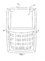
- FIG. 1 illustrates an exemplary portable electronic device, consistent with certain disclosed embodiments
- FIG. 2a illustrates an exemplary keypad assembly, consistent with certain disclosed embodiments
- FIG. 2b illustrates an example light guide used in exemplary keypad assembly, consistent with certain disclosed embodiments
- FIG. 2c illustrates a cutaway diagram of the exemplary keypad assembly of FIG. 2a , consistent with certain disclosed embodiments.
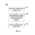
- FIG. 3 is a flowchart illustrating a method for applying a highly-reflective coating, consistent with certain disclosed embodiments.
- Light sources such as LEDs
- LEDs may be provided on a printed substrate, and light may be transmitted to an entire keypad assembly via a light guide. LEDs may be disposed between keys, rather than vertically aligned with any given key.
- a light source feature may be vertically disposed above the LED.
- one or more light guide features may be disposed throughout the light guide to redirect light from the LEDs.
- keypad assemblies In some keypad assemblies, a large number of LEDs may be required to light an entire keypad. Often in keypad assemblies, the light emitted from the LEDs to the keys may be lost through the light guide and light source features, so that the illumination of the keys becomes non-uniform and dark. In addition, keypad assemblies may be prone to light losses and light hot spots, and may not provide optimal brightness, light uniformity, and improved light distribution.
- a keypad assembly for a portable electronic device comprises: a keypad including a plurality of keys; a light guide for transmitting light from at least one light source, wherein the light guide includes at least one light source feature and at least one light guide feature, and the at least one light guide feature and the at least one light source feature have applied thereto a reflective coating.
- a light guide for transmitting light from at least one light source comprises: at least one light source feature; and at least one light guide feature, wherein the at least one light guide feature and the at least one light source feature have applied thereto a reflective coating.
- FIG. 1 is a diagram of an example handheld electronic device 100 in which systems and methods consistent with the present disclosure may be implemented.
- FIG. 1 illustrates an example handheld electronic device 100 having keys arranged according to a QWERTY key arrangement. That is, handheld electronic device 100 of FIG. 1 is an embodiment having an arrangement of Latin letters associated with keys 130 where the letters are generally presented in an order corresponding to the order of a standard QWERTY keyboard.
- handheld electronic device 100 may include display 110, keypad 120, and keys 130.
- Display 110 may be any type of visual input/output configured to display one or more characters and/or receive input corresponding to one or more characters.
- display 110 may be configured to display one or more diagrams, figures, pictures, words, etc. and/or to receive input corresponding to one or more diagrams, figures, pictures, words, characters, etc.
- display 110 may be touch-screen display 110, and may be configured to display respective representations of keypad 120 (i.e., virtual keypad) and keys 130 (i.e., virtual keys).
- Keypad 120 may include any combination of keys 130. Keypad 120 and keys 130 may be of any configuration, such as a standard ITU E.161 key arrangement, an AZERTY key arrangement, a QWERTY key arrangement, a reduced QWERTY key arrangement, or other key arrangement whether reduced or not reduced. Although keypad 120 illustrated in FIG. 1 is configured such that it is on a generally same planar surface as display 110, in other embodiments, keypad 120 may be configured such that it is on a different planar surface than display 120, i.e., a so-called "pull-out” or "slidable” keypad 120.
- Keys 130 may include buttons by which input may be received from a user. Each key 130 may be assigned one or more characters, symbols, codes, and/or operations. In some embodiments, keys 130 may be touch-sensitive, i.e., input may be received by one or more touches from a user. For example, characters associated with keys 130 in example handheld electronic device 100 can be selected by tapping or pressing on keys 130. That is, one or more characters may be associated with each key 130 such that when a user selects a desired key 130 an associated character may be displayed on display 110.
- Characters may include, without limitation, any type of visual representation including, for example, Unicode characters; words in any language (e.g., Latin, Arabic, Cyrillic, Greek, etc.); letters in any language; digits of any numbering system (e.g., Roman, Arabic, decimal, hexadecimal, etc.); diacritical marks, such as accents (e.g., acute, double acute, grave, double grave, etc.), breve, caron, cedilla, circumflex, diaeresis, dot, hook, horn, macron, etc.; punctuation (e.g., period, comma, semicolon, colon, etc.); symbols and marks (e.g., tilde, hash, percentage, ampersand, bar, hyphen, etc.); mathematical operators (e.g., plus, minus, equal, etc.); superscripts and subscripts; emoticons; etc.
- characters may be printed on keys 130.
- FIGS. 2a , 2b , and 2c are diagrams illustrating an example keypad assembly 200, consistent with certain disclosed embodiments.
- FIG. 2a is a top-level view of keypad assembly 200
- FIG. 2b is a three-dimensional diagram illustrating an example light guide 210 of keypad assembly 200 of FIG. 2a
- FIG. 2c is a cut-away diagram of keypad assembly 200 of FIG. 2a .
- Keypad assembly 200 may be used in a handheld electronic device, such as handheld electronic device 100 of FIG. 1 , although the assembly may also be adapted to keypads for other classes of devices.
- keypad assembly 200 may include light guide 210, light guide features 220, and light source features 230.
- Light guide 210 may be made of a material having a good transmittance in the visible light region, thereby allowing the light to be channeled through light guide 210. That is, light guide 210 may be comprised of any material that allows a maximum intensity of light rays to pass within light guide 210 with little change in direction caused by the material of light guide 210.
- light guide 210 may be plastic.
- light guide 210 may be Acrylonitrile Butadiene Styrene (ABS), polypropylene, styrene, etc.
- Light guide 210 may include both negative features (e.g., indentations) and positive features (e.g., protrusions). These negative and positive features of light guide 210 may be used to cause the direction of light waves through light guide 210 to be refracted and changed.
- the negative and positive features may be introduced by any method of plastic forming known in the art, including, for example, injection molding, vacuum forming, thermal forming, etc.
- light guide features 220 and light source features 230 illustrated in example light guide 210 are negative features.
- light guide features 220 and light source features 230 may be small cut-out feature surfaces in light guide 210 that serve to bounce and move light within light guide 210.
- light guide features 220 may be negative features on the bottom plane of light guide 210
- light source features 230 may be negative features on the top plane of light guide 210.
- the relative location of light guide features 220 to keys 130 and light source features 230 to light sources 250 may be determined so as to cause light guide features 220 and light source features 230 to reflect the light from one or more light sources 250 to keys 130, giving a more uniform brightness to keypad 120.
- the number and location of light guide features 220 may be determined based on the number and arrangement of keys 130, and the number and location of light source features 230 may be determined based on the number and location of light sources 250.
- light guide features 220 may be placed at other positions that are not dependent on the arrangement of keys 130. For example, it may be desirable to position light guide features 220 at positions from which the light guide features 220 can direct sufficient light toward keys 130 at the edges of keypad 120, which can be relatively dark.
- Light guide features 220 and light source features 230 may be of any shape and may have one or more angles and/or inclined surfaces. In some embodiments, the shapes of light guide features 220 and light source features 230 may be determined according to desired reflection angles and/or directions. The shapes of light guide features 220 and light source features 230 may be convex and/or concave and may include, for example, polygonal shapes, triangular shapes (right, isosceles, obtuse, scalene, equilateral, etc.), pyramidal shapes, conical shapes, semi-conical shapes, etc. For example, light guide features 220 of FIGS.
- FIGS. 2a-2c are illustrated as triangular in shape, having three surfaces that are inclined relative to a horizontal bottom plane of light guide 210 (e.g., surfaces 225 of FIG. 2b ).
- light source features 230 of FIGS. 2a-2c are shown with two surfaces (e.g., surfaces 23 5 a of FIG. 2b ) that are inclined relative to a horizontal top plane of light guide 210, and two surfaces (e.g., surfaces 235b of FIG. 2b ) that are perpendicular to the horizontal top plane of light guide 210.
- FIG. 2c is a cut-away diagram of FIG. 2a illustrating key assembly 200 in which a highly-reflective coating 260 has been applied to light guide 210.
- FIG. 2c illustrates an embodiment in which light source feature 230 has an associated light source 250 disposed below, and the light source feature 230 has applied thereto a reflective coating.
- Reflective coatings may be any suitable metallic material and/or any reflective coating layer coated on the metallic material. Suitable materials may include materials having a higher refractive index than light guide 210. For example, highly-reflective coating may be metallic sheeting or film, plastic sheeting or film, etc.
- one or more keys 130 may be proximally disposed on a top planar surface of light guide 210.
- keys 130 may be communicatively coupled to one or more processing devices that receive signals from keys 130 and process the received signals.
- processing devices that receive signals from keys 130 and process the received signals.
- light guide feature 230 may be vertically disposed above light source 250.
- light source 250 may be disposed at other locations, including on a centerline of the keys.
- the number and location of light sources 250 may be determined, for example, by user constraints, a layout of the keys, an optimal or desired design for a particular keypad, an optimal or desired level of brightness and uniformity, etc.
- Light source 250 may be optically coupled with light guide 210 for transmission of light into light guide 210.
- light source 250 may be secured to a corner, edge, or other proximate location of light guide 210 using an optical adhesive.
- Light source 250 may be electrically coupled to a power source, such as, for example, a battery in handheld device 100.
- Light sources 250 may include, for example, LEDs, edge-emitting LEDs, organic LEDs (OLEDs), etc.
- reflective, highly reflective, or mirror-like coatings or materials may be applied to, or otherwise incorporated in, light guide features 220 and light source features 230.
- the light from light sources 250 is mostly transmitted in a direction that is vertical to the top and bottom planar surfaces of light guide 210, while very little, if any, light is transmitted in a horizontal direction of light guide 210.
- the light transmitted from light sources 250 is directed by means of light source features 230 to light guide 210, which in turn horizontally transmits the light toward keys 130.
- the light introduced to light guide 210 may be subjected to nearly complete reflection at the boundary between light guide 210 and light source feature 230, so that almost all of the light is transmitted through light guide 210.
- FIG. 2c illustrates the application of a highly-reflective coating to light source features 230
- a highly-reflective coating maybe similarly applied to light guide features 220 (not shown).
- the reflective coating or material is applied to internal light guide features 220, more light will be directed throughout light guide 210, and less light may be lost through the surface faces of light guide features 220.
- FIG. 3 is an example flowchart 300 illustrating application of a highly-reflective coating to light guide features 220 and light source features 230, in accordance with certain implementations. Specifically, FIG. 3 illustrates a flowchart 300 consistent with example implementations of the present disclosure in which highly-reflective coating is applied to light guide features 220 and light source features 230 of light guide 210 for use in a handheld electronic device, such as handheld electronic device 100.
- one or more areas of light guide 210 are masked (step 310).
- the one or more masked areas may include areas on a top planar surface, a bottom planar surface, and one or more side surfaces of light guide 210.
- light guide features 220 and light source features 230 may be left unmasked, or exposed.
- a highly-reflective coating may be applied to the unmasked or exposed areas, such as light guide features 220 and light sources features 230 (step 320).
- light guide 210 is placed in a chamber and a vacuum metallization (VM) or non-conductive vacuum metallization (NCVM) technique is used to apply the highly-reflective coating.
- VM and NCVM techniques metals may be applied to the one or more unmasked areas within a vacuum chamber by a deposition process.
- the metals may include any metal alloy. In some embodiments, the metal is an aluminum alloy.
- the masking is removed from the one or more areas of light guide 210 (step 330).
- the material of light guide 210 is a clear material, reflective layer 260 may be reflective on both sides of the light guide feature 220 face and/or light source feature 230 face to which it is applied.
- the reflective material when a reflective material is used, rather than a reflective coating, the reflective material may be cut into appropriate shapes from a reflective material sheet. The reflective material shapes may then be manually (or by machine, if possible) placed into the light guide features 220 and/or light source features 230.
Landscapes
- Physics & Mathematics (AREA)
- General Physics & Mathematics (AREA)
- Optics & Photonics (AREA)
- Input From Keyboards Or The Like (AREA)
Priority Applications (2)
| Application Number | Priority Date | Filing Date | Title |
|---|---|---|---|
| EP20110159084 EP2503578A1 (de) | 2011-03-21 | 2011-03-21 | System und Verfahren für optische Funktionen eines Tastaturlichtleiters und Beschichtungen |
| CA 2768430 CA2768430A1 (en) | 2011-03-21 | 2012-02-16 | System and method for keypad light guide optical features and coatings |
Applications Claiming Priority (1)
| Application Number | Priority Date | Filing Date | Title |
|---|---|---|---|
| EP20110159084 EP2503578A1 (de) | 2011-03-21 | 2011-03-21 | System und Verfahren für optische Funktionen eines Tastaturlichtleiters und Beschichtungen |
Publications (1)
| Publication Number | Publication Date |
|---|---|
| EP2503578A1 true EP2503578A1 (de) | 2012-09-26 |
Family
ID=44351414
Family Applications (1)
| Application Number | Title | Priority Date | Filing Date |
|---|---|---|---|
| EP20110159084 Ceased EP2503578A1 (de) | 2011-03-21 | 2011-03-21 | System und Verfahren für optische Funktionen eines Tastaturlichtleiters und Beschichtungen |
Country Status (2)
| Country | Link |
|---|---|
| EP (1) | EP2503578A1 (de) |
| CA (1) | CA2768430A1 (de) |
Cited By (1)
| Publication number | Priority date | Publication date | Assignee | Title |
|---|---|---|---|---|
| EP3745692A4 (de) * | 2019-03-26 | 2021-03-24 | NEC Platforms, Ltd. | Led-lichtquellenmechanismus, telefongerät und verfahren zur formung einer led-lichtquelle |
Citations (8)
| Publication number | Priority date | Publication date | Assignee | Title |
|---|---|---|---|---|
| US5128842A (en) * | 1991-06-03 | 1992-07-07 | Sunarrow Co., Inc. | Uniform illumination plate |
| DE202004003550U1 (de) * | 2003-03-07 | 2004-07-01 | Behavior Tech Computer Corp. | Dateneingabevorrichtung mit einem Hintergrundbeleuchtungsmodul |
| EP1739934A1 (de) * | 2005-06-28 | 2007-01-03 | Samsung Electronics Co., Ltd. | Tastaturblock für ein tragbares Endgerät |
| WO2007100180A1 (en) * | 2006-02-28 | 2007-09-07 | Attocon Co., Ltd. | Light emitting keypad comprising light guide film and light guide film |
| US20080019115A1 (en) * | 2006-07-20 | 2008-01-24 | Ls Tech Co., Led. | Back light unit |
| US20080037277A1 (en) * | 2006-08-09 | 2008-02-14 | Kabushiki Kaisha Tokai Rika Denki Seisakusho | Operation Device |
| US20090103964A1 (en) * | 2007-10-17 | 2009-04-23 | Oki Electric Industry Co., Ltd. | Key switch arrangement having an illuminating function |
| US20100170775A1 (en) * | 2009-01-05 | 2010-07-08 | Samsung Electronics Co., Ltd. | Keypad assembly and manufacturing method thereof |
-
2011
- 2011-03-21 EP EP20110159084 patent/EP2503578A1/de not_active Ceased
-
2012
- 2012-02-16 CA CA 2768430 patent/CA2768430A1/en not_active Abandoned
Patent Citations (8)
| Publication number | Priority date | Publication date | Assignee | Title |
|---|---|---|---|---|
| US5128842A (en) * | 1991-06-03 | 1992-07-07 | Sunarrow Co., Inc. | Uniform illumination plate |
| DE202004003550U1 (de) * | 2003-03-07 | 2004-07-01 | Behavior Tech Computer Corp. | Dateneingabevorrichtung mit einem Hintergrundbeleuchtungsmodul |
| EP1739934A1 (de) * | 2005-06-28 | 2007-01-03 | Samsung Electronics Co., Ltd. | Tastaturblock für ein tragbares Endgerät |
| WO2007100180A1 (en) * | 2006-02-28 | 2007-09-07 | Attocon Co., Ltd. | Light emitting keypad comprising light guide film and light guide film |
| US20080019115A1 (en) * | 2006-07-20 | 2008-01-24 | Ls Tech Co., Led. | Back light unit |
| US20080037277A1 (en) * | 2006-08-09 | 2008-02-14 | Kabushiki Kaisha Tokai Rika Denki Seisakusho | Operation Device |
| US20090103964A1 (en) * | 2007-10-17 | 2009-04-23 | Oki Electric Industry Co., Ltd. | Key switch arrangement having an illuminating function |
| US20100170775A1 (en) * | 2009-01-05 | 2010-07-08 | Samsung Electronics Co., Ltd. | Keypad assembly and manufacturing method thereof |
Cited By (2)
| Publication number | Priority date | Publication date | Assignee | Title |
|---|---|---|---|---|
| EP3745692A4 (de) * | 2019-03-26 | 2021-03-24 | NEC Platforms, Ltd. | Led-lichtquellenmechanismus, telefongerät und verfahren zur formung einer led-lichtquelle |
| US11293604B2 (en) | 2019-03-26 | 2022-04-05 | Nec Platforms, Ltd. | LED light source mechanism, telephone set, and method for forming LED light source |
Also Published As
| Publication number | Publication date |
|---|---|
| CA2768430A1 (en) | 2012-09-21 |
Similar Documents
| Publication | Publication Date | Title |
|---|---|---|
| TWI441044B (zh) | Self-luminous board with keyboard | |
| EP2765485A1 (de) | Leuchtende Tastatur und Lichtleiterplatte dafür | |
| CN101512697A (zh) | 键盘光导装置 | |
| US20130021297A1 (en) | Touch panel | |
| US9189078B2 (en) | Enhancing keycap legend visibility with optical components | |
| US20110291938A1 (en) | Touch-type transparent keyboard | |
| CN112563060B (zh) | 键盘背光模块及其制造方法 | |
| US20140085860A1 (en) | Light guide module for keypad | |
| CN104701055A (zh) | 发光键盘 | |
| US20120154180A1 (en) | Light guide structure, keypad structure including the same, and method of fabricating the same | |
| TWM482759U (zh) | 應用於鍵盤背光模組破孔處之防漏光微結構 | |
| CN202871648U (zh) | 薄型化的发光键盘 | |
| US10915615B2 (en) | Sensing device and terminal device | |
| CN102254725A (zh) | 发光键盘 | |
| EP2503578A1 (de) | System und Verfahren für optische Funktionen eines Tastaturlichtleiters und Beschichtungen | |
| US20120241297A1 (en) | System and Method for Keypad Light Guide Optical Features and Coatings | |
| US20140369021A1 (en) | Luminous keyboard device | |
| US20050073826A1 (en) | Light guide plate with multiple visible regions | |
| US8219166B2 (en) | Manufacturing of back lighting structure for mobile terminal | |
| CN202067706U (zh) | 发光键盘 | |
| US12306679B2 (en) | System and method of manufacturing a haptic touchpad and palm rest assembly with light-diffusing composite substrate of woven glass fiber impregnated with polycarbonate | |
| US20050073824A1 (en) | Thin lighting panel with multiple visible regions | |
| US12204705B2 (en) | System and method of manufacturing a three- panel thermoplastic fiberglass composite haptic touchpad and palm rest assembly for an information handling system | |
| CN205542526U (zh) | 键盘背光模块 | |
| JP2018010394A (ja) | 入力装置 |
Legal Events
| Date | Code | Title | Description |
|---|---|---|---|
| PUAI | Public reference made under article 153(3) epc to a published international application that has entered the european phase |
Free format text: ORIGINAL CODE: 0009012 |
|
| 17P | Request for examination filed |
Effective date: 20110321 |
|
| AK | Designated contracting states |
Kind code of ref document: A1 Designated state(s): AL AT BE BG CH CY CZ DE DK EE ES FI FR GB GR HR HU IE IS IT LI LT LU LV MC MK MT NL NO PL PT RO RS SE SI SK SM TR |
|
| AX | Request for extension of the european patent |
Extension state: BA ME |
|
| RAP1 | Party data changed (applicant data changed or rights of an application transferred) |
Owner name: BLACKBERRY LIMITED |
|
| RAP1 | Party data changed (applicant data changed or rights of an application transferred) |
Owner name: BLACKBERRY LIMITED |
|
| 17Q | First examination report despatched |
Effective date: 20150520 |
|
| STAA | Information on the status of an ep patent application or granted ep patent |
Free format text: STATUS: THE APPLICATION HAS BEEN REFUSED |
|
| 18R | Application refused |
Effective date: 20160607 |