EP2503548B1 - Speech decoding device, speech decoding method, and speech decoding program - Google Patents
Speech decoding device, speech decoding method, and speech decoding program Download PDFInfo
- Publication number
- EP2503548B1 EP2503548B1 EP12171613.8A EP12171613A EP2503548B1 EP 2503548 B1 EP2503548 B1 EP 2503548B1 EP 12171613 A EP12171613 A EP 12171613A EP 2503548 B1 EP2503548 B1 EP 2503548B1
- Authority
- EP
- European Patent Office
- Prior art keywords
- temporal envelope
- unit
- high frequency
- speech
- decoding device
- Prior art date
- Legal status (The legal status is an assumption and is not a legal conclusion. Google has not performed a legal analysis and makes no representation as to the accuracy of the status listed.)
- Active
Links
Images


Classifications
-
- G—PHYSICS
- G10—MUSICAL INSTRUMENTS; ACOUSTICS
- G10L—SPEECH ANALYSIS TECHNIQUES OR SPEECH SYNTHESIS; SPEECH RECOGNITION; SPEECH OR VOICE PROCESSING TECHNIQUES; SPEECH OR AUDIO CODING OR DECODING
- G10L19/00—Speech or audio signals analysis-synthesis techniques for redundancy reduction, e.g. in vocoders; Coding or decoding of speech or audio signals, using source filter models or psychoacoustic analysis
- G10L19/02—Speech or audio signals analysis-synthesis techniques for redundancy reduction, e.g. in vocoders; Coding or decoding of speech or audio signals, using source filter models or psychoacoustic analysis using spectral analysis, e.g. transform vocoders or subband vocoders
- G10L19/03—Spectral prediction for preventing pre-echo; Temporary noise shaping [TNS], e.g. in MPEG2 or MPEG4
-
- G—PHYSICS
- G10—MUSICAL INSTRUMENTS; ACOUSTICS
- G10L—SPEECH ANALYSIS TECHNIQUES OR SPEECH SYNTHESIS; SPEECH RECOGNITION; SPEECH OR VOICE PROCESSING TECHNIQUES; SPEECH OR AUDIO CODING OR DECODING
- G10L19/00—Speech or audio signals analysis-synthesis techniques for redundancy reduction, e.g. in vocoders; Coding or decoding of speech or audio signals, using source filter models or psychoacoustic analysis
- G10L19/02—Speech or audio signals analysis-synthesis techniques for redundancy reduction, e.g. in vocoders; Coding or decoding of speech or audio signals, using source filter models or psychoacoustic analysis using spectral analysis, e.g. transform vocoders or subband vocoders
- G10L19/0204—Speech or audio signals analysis-synthesis techniques for redundancy reduction, e.g. in vocoders; Coding or decoding of speech or audio signals, using source filter models or psychoacoustic analysis using spectral analysis, e.g. transform vocoders or subband vocoders using subband decomposition
- G10L19/0208—Subband vocoders
-
- G—PHYSICS
- G10—MUSICAL INSTRUMENTS; ACOUSTICS
- G10L—SPEECH ANALYSIS TECHNIQUES OR SPEECH SYNTHESIS; SPEECH RECOGNITION; SPEECH OR VOICE PROCESSING TECHNIQUES; SPEECH OR AUDIO CODING OR DECODING
- G10L19/00—Speech or audio signals analysis-synthesis techniques for redundancy reduction, e.g. in vocoders; Coding or decoding of speech or audio signals, using source filter models or psychoacoustic analysis
- G10L19/02—Speech or audio signals analysis-synthesis techniques for redundancy reduction, e.g. in vocoders; Coding or decoding of speech or audio signals, using source filter models or psychoacoustic analysis using spectral analysis, e.g. transform vocoders or subband vocoders
- G10L19/0212—Speech or audio signals analysis-synthesis techniques for redundancy reduction, e.g. in vocoders; Coding or decoding of speech or audio signals, using source filter models or psychoacoustic analysis using spectral analysis, e.g. transform vocoders or subband vocoders using orthogonal transformation
-
- G—PHYSICS
- G10—MUSICAL INSTRUMENTS; ACOUSTICS
- G10L—SPEECH ANALYSIS TECHNIQUES OR SPEECH SYNTHESIS; SPEECH RECOGNITION; SPEECH OR VOICE PROCESSING TECHNIQUES; SPEECH OR AUDIO CODING OR DECODING
- G10L19/00—Speech or audio signals analysis-synthesis techniques for redundancy reduction, e.g. in vocoders; Coding or decoding of speech or audio signals, using source filter models or psychoacoustic analysis
- G10L19/04—Speech or audio signals analysis-synthesis techniques for redundancy reduction, e.g. in vocoders; Coding or decoding of speech or audio signals, using source filter models or psychoacoustic analysis using predictive techniques
- G10L19/06—Determination or coding of the spectral characteristics, e.g. of the short-term prediction coefficients
-
- G—PHYSICS
- G10—MUSICAL INSTRUMENTS; ACOUSTICS
- G10L—SPEECH ANALYSIS TECHNIQUES OR SPEECH SYNTHESIS; SPEECH RECOGNITION; SPEECH OR VOICE PROCESSING TECHNIQUES; SPEECH OR AUDIO CODING OR DECODING
- G10L19/00—Speech or audio signals analysis-synthesis techniques for redundancy reduction, e.g. in vocoders; Coding or decoding of speech or audio signals, using source filter models or psychoacoustic analysis
- G10L19/04—Speech or audio signals analysis-synthesis techniques for redundancy reduction, e.g. in vocoders; Coding or decoding of speech or audio signals, using source filter models or psychoacoustic analysis using predictive techniques
- G10L19/16—Vocoder architecture
- G10L19/167—Audio streaming, i.e. formatting and decoding of an encoded audio signal representation into a data stream for transmission or storage purposes
-
- G—PHYSICS
- G10—MUSICAL INSTRUMENTS; ACOUSTICS
- G10L—SPEECH ANALYSIS TECHNIQUES OR SPEECH SYNTHESIS; SPEECH RECOGNITION; SPEECH OR VOICE PROCESSING TECHNIQUES; SPEECH OR AUDIO CODING OR DECODING
- G10L19/00—Speech or audio signals analysis-synthesis techniques for redundancy reduction, e.g. in vocoders; Coding or decoding of speech or audio signals, using source filter models or psychoacoustic analysis
- G10L19/04—Speech or audio signals analysis-synthesis techniques for redundancy reduction, e.g. in vocoders; Coding or decoding of speech or audio signals, using source filter models or psychoacoustic analysis using predictive techniques
- G10L19/16—Vocoder architecture
- G10L19/18—Vocoders using multiple modes
- G10L19/24—Variable rate codecs, e.g. for generating different qualities using a scalable representation such as hierarchical encoding or layered encoding
-
- G—PHYSICS
- G10—MUSICAL INSTRUMENTS; ACOUSTICS
- G10L—SPEECH ANALYSIS TECHNIQUES OR SPEECH SYNTHESIS; SPEECH RECOGNITION; SPEECH OR VOICE PROCESSING TECHNIQUES; SPEECH OR AUDIO CODING OR DECODING
- G10L19/00—Speech or audio signals analysis-synthesis techniques for redundancy reduction, e.g. in vocoders; Coding or decoding of speech or audio signals, using source filter models or psychoacoustic analysis
- G10L19/04—Speech or audio signals analysis-synthesis techniques for redundancy reduction, e.g. in vocoders; Coding or decoding of speech or audio signals, using source filter models or psychoacoustic analysis using predictive techniques
- G10L19/26—Pre-filtering or post-filtering
-
- G—PHYSICS
- G10—MUSICAL INSTRUMENTS; ACOUSTICS
- G10L—SPEECH ANALYSIS TECHNIQUES OR SPEECH SYNTHESIS; SPEECH RECOGNITION; SPEECH OR VOICE PROCESSING TECHNIQUES; SPEECH OR AUDIO CODING OR DECODING
- G10L21/00—Speech or voice signal processing techniques to produce another audible or non-audible signal, e.g. visual or tactile, in order to modify its quality or its intelligibility
- G10L21/02—Speech enhancement, e.g. noise reduction or echo cancellation
- G10L21/038—Speech enhancement, e.g. noise reduction or echo cancellation using band spreading techniques
-
- G—PHYSICS
- G10—MUSICAL INSTRUMENTS; ACOUSTICS
- G10L—SPEECH ANALYSIS TECHNIQUES OR SPEECH SYNTHESIS; SPEECH RECOGNITION; SPEECH OR VOICE PROCESSING TECHNIQUES; SPEECH OR AUDIO CODING OR DECODING
- G10L21/00—Speech or voice signal processing techniques to produce another audible or non-audible signal, e.g. visual or tactile, in order to modify its quality or its intelligibility
- G10L21/04—Time compression or expansion
Definitions
- the present invention relates to a speech decoding device, a speech decoding method, and a speech decoding program.
- Speech and audio coding techniques for compressing the amount of data of signals into a few tenths by removing information not required for human perception by using psychoacoustics are extremely important in transmitting and storing signals.
- Examples of widely used perceptual audio coding techniques include "MPEG4 AAC” standardized by "ISO/IEC MPEG”.
- a bandwidth extension technique for generating high frequency components by using low frequency components of speech has been widely used in recent years as a method for improving the performance of speech encoding and obtaining a high speech quality at a low bit rate.
- Typical examples of the bandwidth extension technique include SBR (Spectral Band Replication) technique used in "MPEG4 AAC".
- SBR Spectral Band Replication
- a high frequency component is generated by converting a signal into a spectral region by using a QMF (Quadrature Mirror Filter) filterbank and copying spectral coefficients from a low frequency band to a high frequency band with respect to the transformed signal, and the high frequency component is adjusted by adjusting the spectral envelope and tonality of the copied coefficients as is disclosed for example in the article by S. Meltzer and G.
- the spectral envelope and tonality of the spectral coefficients represented in the frequency domain are adjusted, by adjusting a gain for the spectral coefficients, performing linear prediction inverse filtering in a temporal direction, and superimposing noise on the spectral coefficient.
- a reverberation noise called a pre-echo or a post-echo may be perceived in the decoded signal.
- a problem similar to that of the pre-echo and post-echo also occurs in multi-channel audio coding using a parametric process represented by "MPEG Surround” and Parametric Stereo.
- a decoder used in multi-channel audio coding includes means for performing decorrelation on a decoded signal using a reverberation filter.
- the temporal envelope of the signal is transformed during the decorrelation, thereby causing degradation of a reproduction signal similar to that of the pre-echo and post-echo.
- Solutions for the problem include a TES (Temporal Envelope Shaping) technique (Patent Literature 1).
- a linear prediction analysis is performed in a frequency direction on a signal represented in a QMF domain on which decorrelation has not yet been performed to obtain linear prediction coefficients, and, using the linear prediction coefficients, linear prediction synthesis filtering is performed in the frequency direction on the signal on which decorrelation has been performed.
- This process allows the TES technique to extract the temporal envelope of a signal on which decorrelation has not yet been performed, and in accordance with the extracted temporal envelope, adjust the temporal envelope of the signal on which decorrelation has been performed.
- the temporal envelope of the signal on which decorrelation has been performed is adjusted to a less distorted shape, thereby obtaining a reproduction signal in which the pre-echo and post-echo is improved.
- Patent Literature 1 United States Patent Application Publication No. 2006/0239473
- the TES technique described above is a technique utilizing the fact that a signal on which decorrelation has not yet been performed has a less distorted temporal envelope.
- an SBR decoder the high frequency component of a signal is copied from the low frequency component of the signal. Accordingly, it is not possible to obtain a less distorted temporal envelope with respect to the high frequency component.
- One of the solutions for this problem is a method of analyzing the high frequency component of an input signal in an SBR encoder, quantizing the linear prediction coefficients obtained as a result of the analysis, and multiplexing them into a bit stream to be transmitted. This method allows the SBR decoder to obtain linear prediction coefficients including information with less distorted temporal envelope of the high frequency component.
- the present invention is intended to reduce the occurrence of pre-echo and post-echo and improve the subjective quality of the decoded signal, without significantly increasing the bit rate in the bandwidth extension technique in the frequency domain represented by SBR.
- a speech decoding device of the present invention is a speech decoding device for decoding an encoded speech signal and including: bit stream separating means for separating a bit stream received from outside the speech decoding device that includes the encoded speech signal into an encoded bit stream and temporal envelope supplementary information; core decoding means for decoding the encoded bit stream separated by the bit stream separating means to obtain a low frequency component; frequency transform means for transforming the low frequency component obtained by the core decoding means to a frequency domain; high frequency generating means for generating a high frequency component by copying the low frequency component transformed into the frequency domain by the frequency transform means from low frequency bands to high frequency bands; low frequency temporal envelope analysis means for calculating the low frequency component transformed into the frequency domain by the frequency transform means to obtain temporal envelope information; temporal envelope adjusting means for adjusting the temporal envelope information obtained by the low frequency temporal envelope analysis means by using the temporal envelope supplementary information, and temporal envelope shaping means for shaping a temporal envelope of the high frequency component generated by the high frequency generating means by using the temporal
- the speech decoding device of the present invention further include high frequency adjusting means for adjusting the high frequency component
- the frequency transform means may be a 64-division QMF filterbank with a real or complex coefficient
- the frequency transform means, the high frequency generating means, and the high frequency adjusting means operate based on a Spectral Band Replication (SBR) decoder for "MPEG4 AAC” defined in "ISO/IEC 14496-3".
- SBR Spectral Band Replication
- the low frequency temporal envelope analysis means perform linear prediction analysis in a frequency direction on the low frequency component transformed into the frequency domain by the frequency transform means to obtain low frequency linear prediction coefficients
- the temporal envelope adjusting means may adjust the low frequency linear prediction coefficients by using the temporal envelope supplementary information
- the temporal envelope shaping means may perform linear prediction filtering in a frequency direction on the high frequency component in the frequency domain generated by the high frequency generating means, by using linear prediction coefficients adjusted by the temporal envelope adjusting means, to shape a temporal envelope of a speech signal.
- the low frequency temporal envelope analysis means obtain temporal envelope information of a speech signal by obtaining power of each time slot of the low frequency component transformed into the frequency domain by the frequency transform means, the temporal envelope adjusting means adjust the temporal envelope information by using the temporal envelope supplementary information, and the temporal envelope shaping means superimpose the adjusted temporal envelope information on the high frequency component in the frequency domain generated by the high frequency generating means to shape a temporal envelope of a high frequency component.
- the low frequency temporal envelope analysis means obtain temporal envelope information of a speech signal by obtaining power of each QMF subband sample of the low frequency component transformed into the frequency domain by the frequency transform means, the temporal envelope adjusting means adjust the temporal envelope information by using the temporal envelope supplementary information, and the temporal envelope shaping means shape a temporal envelope of a high frequency component by multiplying the high frequency component in the frequency domain generated by the high frequency generating means by the adjusted temporal envelope information.
- the temporal envelope supplementary information preferably represents a filter strength parameter used for adjusting strength of linear prediction coefficients.
- the temporal envelope supplementary information preferably represents a parameter indicating magnitude of temporal variation of the temporal envelope information.
- the temporal envelope supplementary information preferably includes differential information of linear prediction coefficients with respect to the low frequency linear prediction coefficients.
- the differential information preferably represents a difference between linear prediction coefficients in at least any domain of LSP (Linear Spectrum Pair), ISP (Immittance Spectrum Pair), LSF (Linear Spectrum Frequency), ISF (Immittance Spectrum Frequency), and PARCOR coefficient.
- LSP Linear Spectrum Pair
- ISP Immittance Spectrum Pair
- LSF Linear Spectrum Frequency
- ISF Immittance Spectrum Frequency
- PARCOR coefficient preferably represents a difference between linear prediction coefficients in at least any domain of LSP (Linear Spectrum Pair), ISP (Immittance Spectrum Pair), LSF (Linear Spectrum Frequency), ISF (Immittance Spectrum Frequency), and PARCOR coefficient.
- the low frequency temporal envelope analysis means perform linear prediction analysis in a frequency direction on the low frequency component transformed into the frequency domain by the frequency transform means to obtain the low frequency linear prediction coefficients, and obtain power of each time slot of the low frequency component in the frequency domain to obtain temporal envelope information of a speech signal
- the temporal envelope adjusting means adjust the low frequency linear prediction coefficients by using the temporal envelope supplementary information and adjust the temporal envelope information by using the temporal envelope supplementary information
- the temporal envelope shaping means perform linear prediction filtering in a frequency direction on the high frequency component in the frequency domain generated by the high frequency generating means by using the linear prediction coefficients adjusted by the temporal envelope adjusting means to shape a temporal envelope of a speech signal, and shape a temporal envelope of the high frequency component by convolving the high frequency component in the frequency domain with the temporal envelope information adjusted by the temporal envelope adjusting means.
- the low frequency temporal envelope analysis means perform linear prediction analysis in a frequency direction on the low frequency component transformed into the frequency domain by the frequency transform means to obtain the low frequency linear prediction coefficients, and obtain temporal envelope information of a speech signal by obtaining power of each QMF subband sample of the low frequency component in the frequency domain
- the temporal envelope adjusting means adjust the low frequency linear prediction coefficient by using the temporal envelope supplementary information and adjust the temporal envelope information by using the temporal envelope supplementary information
- the temporal envelope shaping means perform linear prediction filtering in a frequency direction on a high frequency component in the frequency domain generated by the high frequency generating means by using linear prediction coefficients adjusted by the temporal envelope adjusting means to shape a temporal envelope of a speech signal, and shape a temporal envelope of the high frequency component by multiplying the high frequency component in the frequency domain by the temporal envelope information adjusted by the temporal envelope adjusting means.
- the temporal envelope supplementary information preferably represents a parameter indicating both filter strength of linear prediction coefficients and magnitude of temporal variation of the temporal envelope information.
- a speech decoding method of the present invention is a speech decoding method using a speech decoding device for decoding an encoded speech signal and including: a bit stream separating step in which the speech decoding device separates a bit stream received from outside the speech decoding device that includes the encoded speech signal into an encoded bit stream and temporal envelope supplementary information; a core decoding step in which the speech decoding device obtains a low frequency component by decoding the encoded bit stream separated in the bit stream separating step; a frequency transform step in which the speech decoding device transforms the low frequency component obtained in the core decoding step into a frequency domain; a high frequency generating step in which the speech decoding device generates a high frequency component by copying the low frequency component transformed into the frequency domain in the frequency transform step from a low frequency band to a high frequency band; a low frequency temporal envelope analysis step in which the speech decoding device obtains temporal envelope information by analyzing the low frequency component transformed into the frequency domain in the frequency transform step; a temporal envelope adjusting step in which the speech
- a speech decoding program of the present invention for decoding an encoded speech signal causes a computer device to function as: bit stream separating means for separating a bit stream received from outside the speech decoding program that includes the encoded speech signal into an encoded bit stream and temporal envelope supplementary information; core decoding means for decoding the encoded bit stream separated by the bit stream separating means to obtain a low frequency component; frequency transform means for transforming the low frequency component obtained by the core decoding means into a frequency domain; high frequency generating means for generating a high frequency component by copying the low frequency component transformed into the frequency domain by the frequency transform means from a low frequency band to a high frequency band; low frequency temporal envelope analysis means for analyzing the low frequency component transformed into the frequency domain by the frequency transform means to obtain temporal envelope information; temporal envelope adjusting means for adjusting the temporal envelope information obtained by the low frequency temporal envelope analysis means by using the temporal envelope supplementary information; and temporal envelope shaping means for shaping a temporal envelope of the high frequency component generated by the high frequency generating means by using
- a speech decoding program of the present invention for decoding an encoded speech signal causes a computer device to function as: bit steam separating means for separating a bit stream that includes the encoded speech signal into an encoded bit stream and linear prediction coefficients. The bit stream received from outside the speech decoding program.
- the temporal envelope shaping means after performing the linear prediction filtering in the frequency direction on the high frequency component in the frequency domain generated by the high frequency generating means, preferably adjusts power of a high frequency component obtained as a result of the linear prediction filtering to a value equivalent to that before the linear prediction filtering.
- the temporal envelope shaping means after performing the linear prediction filtering in the frequency direction on the high frequency component in the frequency domain generated by the high frequency generating means, preferably adjusts power in a certain frequency range of a high frequency component obtained as a result of the linear prediction filtering to a value equivalent to that before the linear prediction filtering.
- the temporal envelope supplementary information is preferably a ratio of a minimum value to an average value of the adjusted temporal envelope information.
- the temporal envelope shaping means after controlling a gain of the adjusted temporal envelope so that power of the high frequency component in the frequency domain in an SBR envelope time segment is equivalent before and after shaping of the temporal envelope, preferably shape a temporal envelope of the high frequency component by multiplying the temporal envelope whose gain is controlled by the high frequency component in the frequency domain.
- the low frequency temporal envelope analysis means preferably obtains power of each QMF subband sample of the low frequency component transformed to the frequency domain by the frequency transform means, and obtains temporal envelope information represented as a gain coefficient to be multiplied by each of the QMF subband samples, by normalizing the power of each of the QMF subband samples by using average power in an SBR envelope time segment.
- a speech decoding device of the present invention is a speech decoding device for decoding an encoded speech signal and including: core decoding means for obtaining a low frequency component by decoding a bit stream received from outside the decoding device that includes the encoded speech signal; frequency transform means for transforming the low frequency component obtained by the core decoding means into a frequency domain; high frequency generating means for generating a high frequency component by copying the low frequency component transformed into the frequency domain by the frequency transform means from a low frequency band to a high frequency band; low frequency temporal envelope analysis means for analyzing the low frequency component transformed into the frequency domain by the frequency transform means to obtain temporal envelope information; temporal envelope supplementary information generating means for analyzing the bit stream to generate temporal envelope supplementary information; temporal envelope adjusting means for adjusting the temporal envelope information obtained by the low frequency temporal envelope analysis means by using the temporal envelope supplementary information; and temporal envelope shaping means for shaping a temporal envelope of the high frequency component generated by the high frequency generating means by using the temporal envelope information adjusted by the temporal
- the speech decoding device of the present invention include primary high frequency adjusting means and secondary high frequency adjusting means, both corresponding to the high frequency adjusting means, the primary high frequency adjusting means may execute a process including a part of a process corresponding to the high frequency adjusting means, the temporal envelope shaping means may shape a temporal envelope of an output signal of the primary high frequency adjusting means, the secondary high frequency adjusting means may execute a process not executed by the primary high frequency adjusting means among processes corresponding to the high frequency adjusting means on an output signal of the temporal envelope shaping means, and the secondary high frequency adjusting means may be an addition process of a sine wave during SBR decoding.
- the occurrence of pre-echo and post-echo can be reduced and the subjective quality of a decoded signal can be improved without significantly increasing the bit rate in the bandwidth extension technique in the frequency domain represented by SBR.
- FIG 1 is a diagram illustrating a speech encoding device 11 according to a first embodiment.
- the speech encoding device 11 physically includes a CPU, a ROM, a RAM, a communication device, and the like, which are not illustrated, and the CPU integrally controls the speech encoding device 11 by loading and executing a predetermined computer program (such as a computer program for performing processes illustrated in the flowchart of FIG. 2 ) stored in a built-in memory of the speech encoding device 11 such as the ROM into the RAM.
- the communication device of the speech encoding device 11 receives a speech signal to be encoded from outside the speech encoding device 11, and outputs an encoded multiplexed bit stream to the outside of the speech encoding device 11.
- the speech encoding device 11 functionally includes a frequency transform unit 1a (frequency transform means), a frequency inverse transform unit 1b, a core codec encoding unit 1c (core encoding means), an SBR encoding unit 1d, a linear prediction analysis unit 1e (temporal envelope supplementary information calculating means), a filter strength parameter calculating unit 1f (temporal envelope supplementary information calculating means), and a bit stream multiplexing unit 1g (bit stream multiplexing means).
- the frequency transform unit 1a to the bit stream multiplexing unit 1g of the speech encoding device 11 illustrated in FIG. 1 are functions realized when the CPU of the speech encoding device 11 executes the computer program stored in the built-in memory of the speech encoding device 11.
- the CPU of the speech encoding device 11 sequentially executes processes (processes from Step Sa1 to Step Sa7) illustrated in the flowchart of FIG. 2 , by executing the computer program (or by using the frequency transform unit 1a to the bit stream multiplexing unit 1g illustrated in FIG. 1 ).
- Various types of data required to execute the computer program and various types of data generated by executing the computer program are all stored in the built-in memory such as the ROM and the RAM of the speech encoding device 11.
- the frequency transform unit 1a analyzes an input signal received from outside the speech encoding device 11 via the communication device of the speech encoding device 11 by using a multi-division QMF filterbank to obtain a signal q (k, r) in a QMF domain (process at Step Sa1). It is noted that k (0 ⁇ k ⁇ 63) is an index in a frequency direction, and r is an index indicating a time slot.
- the frequency inverse transform unit 1b synthesize a half of coefficients on the low frequency side in the signal of the QMF domain obtained by the frequency transform unit 1a by using the QMF filterbank to obtain a down-sampled time domain signal that includes only low-frequency components of the input signal (process at Step Sa2).
- the core codec encoding unit 1c encodes the down-sampled time domain signal to obtain an encoded bit stream (process at Step Sa3).
- the encoding performed by the core codec encoding unit 1c may be based on a speech coding method represented by a CELP method, or may be based on a audio coding method such as a transformation coding represented by AAC or a TCX (Transform Coded Excitation) method.
- the SBR encoding unit 1d receives the signal in the QMF domain from the frequency transform unit 1a, and performs SBR encoding based on analyzing the power, signal change, tonality, and the like of the high frequency components to obtain SBR supplementary information (process at Step Sa4).
- the QMF analyzing method in the frequency transform unit 1a and the SBR encoding method in the SBR encoding unit 1d are described in detail in, for example, a Literature "3GPP TS 26.404: Enhanced aacPlus encoder SBR part".
- the linear prediction analysis unit 1e receives the signal in the QMF domain from the frequency transform unit 1a, and performs linear prediction analysis in the frequency direction on the high frequency components of the signal to obtain high frequency linear prediction coefficients a H (n, r) (1 ⁇ n ⁇ N) (process at Step Sa5). It is noted that N is a linear prediction order.
- the index r is an index in a temporal direction for a sub-sample of the signals in the QMF domain.
- a covariance method or an autocorrelation method may be used for the signal linear prediction analysis.
- the linear prediction analysis to obtain a H (n, r) is performed on the high frequency components that satisfy k x ⁇ k ⁇ 63 in q (k, r).
- k x is a frequency index corresponding to an upper limit frequency of the frequency band encoded by the core codec encoding unit 1c.
- the linear prediction analysis unit 1e may also perform linear prediction analysis on low frequency components different from those analyzed when a H (n, r) are obtained to obtain low frequency linear prediction coefficients a L (n, r) different from a H (n, r) (linear prediction coefficients according to such low frequency components correspond to temporal envelope information, and is the same in the first embodiment as in the below).
- the linear prediction analysis to obtain a L (n, r) is performed on low frequency components that satisfy 0 ⁇ k ⁇ k x .
- the linear prediction analysis may also be performed on a part of the frequency band included in a section of 0 ⁇ k ⁇ k x .
- the filter strength parameter calculating unit 1f utilizes the linear prediction coefficients obtained by the linear prediction analysis unit 1e to calculate a filter strength parameter (the filter strength parameter corresponds to temporal envelope supplementary information and is the same in the first embodiment as in the below) (process at Step Sa6).
- a prediction gain G H (r) is first calculated from a H (n, r).
- the method for calculating the prediction gain is, for example, described in detail in " Speech Coding, Takehiro Moriya, The Institute of Electronics, Information and Communication Engineers ". If a L (n, r) has been calculated, a prediction gain G L (r) is calculated similarly.
- the filter strength parameter K(r) is a parameter that increases as G H (r) is increased, and for example, can be obtained according to the following expression (1).
- max (a, b) indicates the maximum value of a and b
- min (a, b) indicates the minimum value of a and b.
- K r max ⁇ 0 , min ⁇ 1 , GH r - 1
- K(r) can be obtained as a parameter that increases as G H (r) is increased, and decreases as G L (r) is increased.
- K can be obtained according to the following expression (2).
- K r max ⁇ 0 , min ⁇ 1 , GH r / GL r - 1
- K(r) is a parameter indicating the strength for adjusting the temporal envelope of the high frequency components during the SBR decoding. A value of the prediction gain with respect to the linear prediction coefficients in the frequency direction is increased as the variation of the temporal envelope of a signal in the analysis interval becomes sharp. K(r) is a parameter for instructing a decoder to strengthen the process for sharpening the variation of the temporal envelope of the high frequency components generated by SBR, with the increase of its value.
- K(r) may also be a parameter for instructing a decoder (such as a speech decoding device 21) to weaken the process for sharpening the variation of the temporal envelope of the high frequency components generated by SBR, with the decrease of its value, or may include a value for not executing the process for sharpening the variation of the temporal envelope.
- K(r) representing a plurality of time slots may be transmitted.
- K(r) is transmitted to the bit stream multiplexing unit 1g after being quantized. It is preferable to calculate K(r) representing the plurality of time slots, for example, by calculating an average of K(r) of a plurality of time slots r before quantization is performed. To transmit K(r) representing the plurality of time slots, K(r) may also be obtained from the analysis result of the entire segment formed of the plurality of time slots, instead of independently calculating K(r) from the result of analyzing each time slot such as the expression (2). In this case, K(r) may be calculated, for example, according to the following expression (3).
- mean( ⁇ ) indicates an average value in the segment of the time slots represented by K(r).
- K r max ⁇ 0 , min ⁇ 1 , mean ⁇ G H r / mean G L r - 1
- K(r) may be exclusively transmitted with inverse filter mode information included in the SBR supplementary information described in "ISO/IEC 14496-3 subpart 4 General Audio Coding".
- K(r) is not transmitted for the time slots for which the inverse filter mode information in the SBR supplementary information is transmitted, and the inverse filter mode information (bs_invf_mode in "ISO/IEC 14496-3 subpart 4 General Audio Coding") in the SBR supplementary information need not be transmitted for the time slot for which K(r) is transmitted.
- Information indicating that either K(r) or the inverse filter mode information included in the SBR supplementary information is transmitted may also be added.
- K(r) and the inverse filter mode information included in the SBR supplementary information may be combined to handle as vector information, and perform entropy coding on the vector.
- the combination of K(r) and the value of the inverse filter mode information included in the SBR supplementary information may be restricted.
- the bit stream multiplexing unit 1g multiplexes the encoded bit stream calculated by the core codec encoding unit 1c, the SBR supplementary information calculated by the SBR encoding unit 1d, and K(r) calculated by the filter strength parameter calculating unit 1f, and outputs a multiplexed bit stream (encoded multiplexed bit stream) through the communication device of the speech encoding device 11 (process at Step Sa7).
- FIG. 3 is a diagram illustrating a speech decoding device 21 according to the first embodiment.
- the speech decoding device 21 physically includes a CPU, a ROM, a RAM, a communication device, and the like, which are not illustrated, and the CPU integrally controls the speech decoding device 21 by loading and executing a predetermined computer program (such as a computer program for performing processes illustrated in the flowchart of FIG. 4 ) stored in a built-in memory of the speech decoding device 21 such as the ROM into the RAM.
- a predetermined computer program such as a computer program for performing processes illustrated in the flowchart of FIG. 4
- the communication device of the speech decoding device 21 receives the encoded multiplexed bit stream output from the speech encoding device 11, a speech encoding device 11 a of a modification 1, which will be described later, or a speech encoding device of a modification 2, which will be described later, and outputs a decoded speech signal to outside the speech decoding device 21.
- the speech decoding device 21, as illustrated in FIG 3 functionally includes a bit stream separating unit 2a (bit stream separating means), a core codec decoding unit 2b (core decoding means), a frequency transform unit 2c (frequency transform means), a low frequency linear prediction analysis unit 2d (low frequency temporal envelope analysis means), a signal change detecting unit 2e, a filter strength adjusting unit 2f (temporal envelope adjusting means), a high frequency generating unit 2g (high frequency generating means), a high frequency linear prediction analysis unit 2h, a linear prediction inverse filter unit 2i, a high frequency adjusting unit 2j (high frequency adjusting means), a linear prediction filter unit 2k (temporal envelope shaping means), a coefficient adding unit 2m, and a frequency inverse transform unit 2n.
- bit stream separating unit 2a bit stream separating means
- a core codec decoding unit 2b core decoding means
- a frequency transform unit 2c frequency transform means
- a low frequency linear prediction analysis unit 2d low frequency temporal envelope analysis means
- the bit stream separating unit 2a to an envelope shape parameter calculating unit In of the speech decoding device 21 illustrated in FIG. 3 are functions realized when the CPU of the speech decoding device 21 executes the computer program stored in the built-in memory of the speech decoding device 21.
- the CPU of the speech decoding device 21 sequentially executes processes (processes from Step Sb1 to Step Sb11) illustrated in the flowchart of FIG. 4 , by executing the computer program (or by using the bit stream separating unit 2a to the envelope shape parameter calculating unit In illustrated in FIG. 3 ).
- Various types of data required to execute the computer program and various types of data generated by executing the computer program are all stored in the built-in memory such as the ROM and the RAM of the speech decoding device 21.
- the bit stream separating unit 2a separates the multiplexed bit stream supplied through the communication device of the speech decoding device 21 into a filter strength parameter, SBR supplementary information, and the encoded bit stream.
- the core codec decoding unit 2b decodes the encoded bit stream received from the bit stream separating unit 2a to obtain a decoded signal including only the low frequency components (process at Step Sb1).
- the decoding method may be based on the speech coding method represented by the CELP method, or may be based on audio coding such as the AAC or the TCX (Transform Coded Excitation) method.
- the frequency transform unit 2c analyzes the decoded signal received from the core codec decoding unit 2b by using the multi-division QMF filter bank to obtain a signal q dec (k, r) in the QMF domain (process at Step Sb2). It is noted that k (0 ⁇ k ⁇ 63) is an index in the frequency direction, and r is an index indicating an index for the sub-sample of the signal in the QMF domain in the temporal direction.
- the low frequency linear prediction analysis unit 2d performs linear prediction analysis in the frequency direction on q dec (k, r) of each time slot r, obtained from the frequency transform unit 2c, to obtain low frequency linear prediction coefficients a dec (n, r) (process at Step Sb3).
- the linear prediction analysis is performed for a range of 0 ⁇ k ⁇ k x corresponding to a signal bandwidth of the decoded signal obtained from the core codec decoding unit 2b.
- the linear prediction analysis may be performed on a part of frequency band included in the section of 0 ⁇ k ⁇ k x .
- the signal change detecting unit 2e detects the temporal variation of the signal in the QMF domain received from the frequency transform unit 2c, and outputs it as a detection result T(r).
- the signal change may be detected, for example, by using the method described below.
- the filter strength adjusting unit 2f adjusts the filter strength with respect to a dec (n, r) obtained from the low frequency linear prediction analysis unit 2d to obtain adjusted linear prediction coefficients a adj (n, r), (process at Step Sb4).
- the filter strength is adjusted, for example, according to the following expression (7), by using a filter strength parameter K received through the bit stream separating unit 2a.
- a adj n ⁇ r a dec n ⁇ r ⁇ K ⁇ r n 1 ⁇ n ⁇ N
- the strength may be adjusted according to the following expression (8).
- a adj n ⁇ r a dec n ⁇ r ⁇ K r ⁇ T r n 1 ⁇ n ⁇ N
- the high frequency generating unit 2g copies the signal in the QMF domain obtained from the frequency transform unit 2c from the low frequency band to the high frequency band to generate a signal q exp (k, r) in the QMF domain of the high frequency components (process at Step Sb5).
- the high frequency components are generated according to the HF generation method in SBR in "MPEG4 AAC” . ("ISO/IEC 14496-3 subpart 4 General Audio Coding").
- the high frequency linear prediction analysis unit 2h performs linear prediction analysis in the frequency direction on q exp (k, r) of each of the time slots r generated by the high frequency generating unit 2g to obtain high frequency linear prediction coefficients a exp (n, r) (process at Step Sb6).
- the linear prediction analysis is performed for a range of k x ⁇ k ⁇ 63 corresponding to the high frequency components generated by the high frequency generating unit 2g.
- the linear prediction inverse filter unit 2i performs linear prediction inverse filtering in the frequency direction on a signal in the QMF domain of the high frequency band generated by the high frequency generating unit 2g, using a exp (n, r) as coefficients (process at Step Sb7).
- the linear prediction inverse filtering may be performed from a coefficient at a lower frequency towards a coefficient at a higher frequency, or may be performed in the opposite direction.
- the linear prediction inverse filtering is a process for temporarily flattening the temporal envelope of the high frequency components, before the temporal envelope shaping is performed at the subsequent stage, and the linear prediction inverse filter unit 2i may be omitted. It is also possible to perform linear prediction analysis and inverse filtering on outputs from the high frequency adjusting unit 2j, which will be described later, by the high frequency linear prediction analysis unit 2h and the linear prediction inverse filter unit 2i, instead of performing linear prediction analysis and inverse filtering on the high frequency components of the outputs from the high frequency generating unit 2g.
- the linear prediction coefficients used for the linear prediction inverse filtering may also be a dec (n, r) or a adj (n, r), instead of a exp (n, r).
- the linear prediction coefficients used for the linear prediction inverse filtering may also be linear prediction coefficients a exp,adj (n, r) obtained by performing filter strength adjustment on a exp (n, r).
- the strength adjustment is performed according to the following expression (10), similar to that when a adj (n, r) is obtained.
- a exp , adj n ⁇ r a exp n ⁇ r ⁇ K ⁇ r n 1 ⁇ n ⁇ N
- the high frequency adjusting unit 2j adjusts the frequency characteristics and tonality of the high frequency components of an output from the linear prediction inverse filter unit 2i (process at Step Sb8).
- the adjustment is performed according to the SBR supplementary information received from the bit stream separating unit 2a.
- the processing by the high frequency adjusting unit 2j is performed according to "HF adjustment" step in SBR in "MPEG4 AAC", and is adjusted by performing linear prediction inverse filtering in the temporal direction, the gain adjustment, and the noise addition on the signal in the QMF domain of the high frequency band.
- the details of the processes in the steps described above are described in "ISO/IEC 14496-3 subpart 4 General Audio Coding".
- the frequency transform unit 2c, the high frequency generating unit 2g, and the high frequency adjusting unit 2j all operate according to the SBR decoder in "MPEG4 AAC" defined in "ISO/IEC 14496-3".
- the linear prediction filter unit 2k performs linear prediction synthesis filtering in the frequency direction on a high frequency components q adj (n, r) of a signal in the QMF domain output from the high frequency adjusting unit 2j, by using a adj (n, r) obtained from the filter strength adjusting unit 2f (process at Step Sb9).
- the linear prediction filter unit 2k shapes the temporal envelope of the high frequency components generated based on SBR.
- the coefficient adding unit 2m adds a signal in the QMF domain including the low frequency components output from the frequency transform unit 2c and a signal in the QMF domain including the high frequency components output from the linear prediction filter unit 2k, and outputs a signal in the QMF domain including both the low frequency components and the high frequency components (process at Step Sb10).
- the frequency inverse transform unit 2n processes the signal in the QMF domain obtained from the coefficient adding unit 2m by using a QMF synthesis filter bank. Accordingly, a time domain decoded speech signal including both the low frequency components obtained by the core codec decoding and the high frequency components generated by SBR and whose temporal envelope is shaped by the linear prediction filter is obtained, and the obtained speech signal is output to outside the speech decoding device 21 through the built-in communication device (process at Step Sb11).
- the frequency inverse transform unit 2n may generate inverse filter mode information of the SBR supplementary information for a time slot to which K(r) is transmitted but the inverse filter mode information of the SBR supplementary information is not transmitted, by using inverse filter mode information of the SBR supplementary information with respect to at least one time slot of the time slots before and after the time slot. It is also possible to set the inverse filter mode information of the SBR supplementary information of the time slot to a predetermined mode in advance.
- the frequency inverse transform unit 2n may generate K(r) for a time slot to which the inverse filter data of the SBR supplementary information is transmitted but K(r) is not transmitted, by using K(r) for at least one time slot of the time slots before and after the time slot. It is also possible to set K(r) of the time slot to a predetermined value in advance. The frequency inverse transform unit 2n may also determine whether the transmitted information is K(r) or the inverse filter mode information of the SBR supplementary information, based on information indicating whether K(r) or the inverse filter mode information of the SBR supplementary information is transmitted.
- FIG. 5 is a diagram illustrating a modification (speech encoding device 11a) of the speech encoding device according to the first embodiment.
- the speech encoding device 11a physically includes a CPU, a ROM, a RAM, a communication device, and the like, which are not illustrated, and the CPU integrally controls the speech encoding device 11 a by loading and executing a predetermined computer program stored in a built-in memory of the speech encoding device 11a such as the ROM into the RAM.
- the communication device of the speech encoding device 11a receives a speech signal to be encoded from outside the speech encoding device 11a, and outputs an encoded multiplexed bit stream to the outside of the speech encoding device 11 a.
- the speech encoding device 11a functionally includes a high frequency inverse transform unit 1h, a short-term power calculating unit 1i (temporal envelope supplementary information calculating means), a filter strength parameter calculating unit 1f1 (temporal envelope supplementary information calculating means), and a bit stream multiplexing unit 1g1 (bit stream multiplexing means), instead of the linear prediction analysis unit 1e, the filter strength parameter calculating unit 1f, and the bit stream multiplexing unit 1g of the speech encoding device 11.
- the bit stream multiplexing unit 1g1 has the same function as that of 1G.
- the frequency transform unit 1a to the SBR encoding unit 1d, the high frequency inverse transform unit 1h, the short-term power calculating unit 1i, the filter strength parameter calculating unit 1f1, and the bit stream multiplexing unit 1g1 of the speech encoding device 11a illustrated in FIG. 5 are functions realized when the CPU of the speech encoding device 11a executes the computer program stored in the built-in memory of the speech encoding device 11 a.
- Various types of data required to execute the computer program and various types of data generated by executing the computer program are all stored in the built-in memory such as the ROM and the RAM of the speech encoding device 11 a.
- the high frequency inverse transform unit 1h replaces the coefficients of the signal in the QMF domain obtained from the frequency transform unit 1a with "0", which correspond to the low frequency components encoded by the core codec encoding unit 1c, and processes the coefficients by using the QMF synthesis filter bank to obtain a time domain signal that includes only the high frequency components.
- the short-term power calculating unit 1i divides the high frequency components in the time domain obtained from the high frequency inverse transform unit 1h into short segments, calculates the power, and calculates p(r). As an alternative method, the short-term power may also be calculated according to the following expression (12) by using the signal in the QMF domain.
- the filter strength parameter calculating unit 1f1 detects the changed portion of p(r), and determines a value of K(r), so that K(r) is increased with the large change.
- the value of K(r) for example, can also be calculated by the same method as that of calculating T(r) by the signal change detecting unit 2e of the speech decoding device 21.
- the signal change may also be detected by using other more sophisticated methods.
- the filter strength parameter calculating unit 1f1 may also obtain short-term power of each of the low frequency components and the high frequency components, obtain signal changes Tr(r) and Th(r) of each of the low frequency components and the high frequency components using the same method as that of calculating T(r) by the signal change detecting unit 2e of the speech decoding device 21, and determine the value af K(r) using these.
- K(r) can be obtained according to the following expression (13), where ⁇ is a constant such as 3.0.
- K r max ⁇ 0 , ⁇ ⁇ Th r - Tr r
- a speech encoding device (not illustrated) of a modification 2 of the first embodiment physically includes a CPU, a ROM, a RAM, a communication device, and the like, which are not illustrated, and the CPU integrally controls the speech encoding device of the modification 2 by loading and executing a predetermined computer program stored in a built-in memory of the speech encoding device of the modification 2 such as the ROM into the RAM.
- the communication device of the speech encoding device of the modification 2 receives a speech signal to be encoded from outside the speech encoding device, and outputs an encoded multiplexed bit stream to the outside of the speech encoding device.
- the speech encoding device of the modification 2 functionally includes a linear prediction coefficient differential encoding unit (temporal envelope supplementary information calculating means) and a bit stream multiplexing unit (bit stream multiplexing means) that receives an output from the linear prediction coefficient differential encoding unit, which are not illustrated, instead of the filter strength parameter calculating unit 1f and the bit stream multiplexing unit 1g of the speech encoding device 11.
- the frequency transform unit 1a to the linear prediction analysis unit 1e, the linear prediction coefficient differential encoding unit, and the bit stream multiplexing unit of the speech encoding device of the modification 2 are functions realized when the CPU of the speech encoding device of the modification 2 executes the computer program stored in the built-in memory of the speech encoding device of the modification 2.
- Various types of data required to execute the computer program and various types of data generated by executing the computer program are all stored in the built-in memory such as the ROM and the RAM of the speech encoding device of the modification 2.
- the linear prediction coefficient differential encoding unit calculates differential values a D (n, r) of the linear prediction coefficient according to the following expression (14), by using a H (n, r) of the input signal and a L (n, r) of the input signal.
- a D n ⁇ r a H n ⁇ r - a L n ⁇ r 1 ⁇ n ⁇ N
- the linear prediction coefficient differential encoding unit then quantizes a D (n, r), and transmits them to the bit stream multiplexing unit (structure corresponding to the bit stream multiplexing unit 1g).
- the bit stream multiplexing unit multiplexes a D (n, r) into the bit stream instead of K(r), and outputs the multiplexed bit stream to outside the speech encoding device through the built-in communication device.
- a speech decoding device (not illustrated) of the modification 2 of the first embodiment physically includes a CPU, a ROM, a RAM, a communication device, and the like, which are not illustrated, and the CPU integrally controls the speech decoding device of the modification 2 by loading and executing a predetermined computer program stored in a built-in memory of the speech decoding device of the modification 2 such as the ROM into the RAM.
- the communication device of the speech decoding device of the modification 2 receives the encoded multiplexed bit stream output from the speech encoding device 11, the speech encoding device 11 a according to the modification 1, or the speech encoding device according to the modification 2, and outputs a decoded speech signal to the outside of the speech decoding device.
- the speech decoding device of the modification 2 functionally includes a linear prediction coefficient differential decoding unit, which is not illustrated, instead of the filter strength adjusting unit 2f of the speech decoding device 21.
- the bit stream separating unit 2a to the signal change detecting unit 2e, the linear prediction coefficient differential decoding unit, and the high frequency generating unit 2g to the frequency inverse transform unit 2n of the speech decoding device of the modification 2 are functions realized when the CPU of the speech decoding device of the modification 2 executes the computer program stored in the built-in memory of the speech decoding device of the modification 2.
- Various types of data required to execute the computer program and various types of data generated by executing the computer program are all stored in the built-in memory such as the ROM and the RAM of the speech decoding device of the modification 2.
- the .linear prediction coefficient differential decoding unit obtains a adj (n, r) differentially decoded according to the following expression (15), by using a L (n, r) obtained from the low frequency linear prediction analysis unit 2d and a D (n, r) received from the bit stream separating unit 2a.
- a adj n ⁇ r a dec n ⁇ r + a D n ⁇ r , 1 ⁇ n ⁇ N
- the linear prediction coefficient differential decoding unit transmits a adj (n, r) differentially decoded in this manner to the linear prediction filter unit 2k.
- a D (n, r) may be a differential value in the domain of prediction coefficients as illustrated in the expression (14).
- a D (n, r) may be a value taking a difference of them.
- the differential decoding also has the same expression form.
- FIG. 6 is a diagram illustrating a speech encoding device 12 according to a second embodiment.
- the speech encoding device 12 physically includes a CPU, a ROM, a RAM, a communication device, and the like, which are not illustrated, and the CPU integrally controls the speech encoding device 12 by loading and executing a predetermined computer program (such as a computer program for performing processes illustrated in the flowchart of FIG. 7 ) stored in a built-in memory of the speech encoding device 12 such as the ROM into the RAM.
- the communication device of the speech encoding device 12 receives a speech signal to be encoded from outside the speech encoding device 12, and outputs an encoded multiplexed bit stream to the outside of the speech encoding device 12.
- the speech encoding device 12 functionally includes a linear prediction coefficient decimation unit 1j (prediction coefficient decimation means), a linear prediction coefficient quantizing unit 1k (prediction coefficient quantizing means), and a bit stream multiplexing unit 1g2 (bit stream multiplexing means), instead of the filter strength parameter calculating unit 1f and the bit stream multiplexing unit 1g of the speech encoding device 11.
- FIG. 6 are functions realized when the CPU of the speech encoding device 12 executes the computer program stored in the built-in memory of the speech encoding device 12.
- the CPU of the speech encoding device 12 sequentially executes processes (processes from Step Sa1 to Step Sa5, and processes from Step Sc1 to Step Sc3) illustrated in the flowchart of FIG. 7 , by executing the computer program (or by using the frequency transform unit 1a to the linear prediction analysis unit 1e, the linear prediction coefficient decimation unit 1j, the linear prediction coefficient quantizing unit 1k, and the bit stream multiplexing unit 1g2 of the speech encoding device 12 illustrated in FIG. 6 ).
- Various types of data required to execute the computer program and various types of data generated by executing the computer program are all stored in the built-in memory such as the ROM and the RAM of the speech encoding device 12.
- the linear prediction coefficient decimation unit 1j decimates a H (n, r) obtained from the linear prediction analysis unit 1e in the temporal direction, and transmits a value of a H (n, r) for a part of time slot r i and a value of the corresponding r i , to the linear prediction coefficient quantizing unit 1k (process at Step Sc1). It is noted that 0 ⁇ i ⁇ N ts , and N ts is the number of time slots in a frame for which a H (n, r) is transmitted.
- the decimation of the linear prediction coefficients may be performed at a predetermined time interval, or may be performed at nonuniform time interval based on the characteristics of a H (n, r).
- a method is possible that compares G H (r) of a H (n, r) in a frame having a certain length, and makes a H (n, r), of which G H (r) exceeds a certain value, an object of quantization. If the decimation interval of the linear prediction coefficients is a predetermined interval instead of using the characteristics of a H (n, r), a H (n, r) need not be calculated for the time slot at which the transmission is not performed.
- the linear prediction coefficient quantizing unit 1k quantizes the decimated high frequency linear prediction coefficients a H (n, r i ) received from the linear prediction coefficient decimation unit 1j and indices r i of the corresponding time slots, and transmits them to the bit stream multiplexing unit 1g2 (process at Step Sc2).
- differential values a D (n, r i ) of the linear prediction coefficients may be quantized as the speech encoding device according to the modification 2 of the first embodiment.
- the bit stream multiplexing unit 1g2 multiplexes the encoded bit stream calculated by the core codec encoding unit 1c, the SBR supplementary information calculated by the SBR encoding unit 1d, and indices ⁇ r i ⁇ of time slots corresponding to a H (n, r i ) being quantized and received from the linear prediction coefficient quantizing unit 1k into a bit stream, and outputs the multiplexed bit stream through the communication device of the speech encoding device 12 (process at Step Sc3).
- FIG. 8 is a diagram illustrating a speech decoding device 22 according to the second embodiment.
- the speech decoding device 22 physically includes a CPU, a ROM, a RAM, a communication device, and the like, which are not illustrated, and the CPU integrally controls the speech decoding device 22 by loading and executing a predetermined computer program (such as a computer program for performing processes illustrated in the flowchart of FIG. 9 ) stored in a built-in memory of the speech decoding device 22 such as the ROM into the RAM.
- the communication device of the speech decoding device 22 receives the encoded multiplexed bit stream output from the speech encoding device 12, and outputs a decoded speech signal to outside the speech encoding device 12.
- the speech decoding device 22 functionally includes a bit stream separating unit 2a1 (bit stream separating means), a linear prediction coefficient interpolation/extrapolation unit 2p (linear prediction coefficient interpolation/extrapolation means), and a linear prediction filter unit 2k1. (temporal envelope shaping means) instead of the bit stream separating unit 2a, the low frequency linear prediction analysis unit 2d, the signal change detecting unit 2e, the filter strength adjusting unit 2f, and the linear prediction filter unit 2k of the speech decoding device 21.
- the bit stream separating unit 2a1, the core codec decoding unit 2b, the frequency transform unit 2c, the high frequency generating unit 2g to the high frequency adjusting unit 2j, the linear prediction filter unit 2k1, the coefficient adding unit 2m, the frequency inverse transform unit 2n, and the linear prediction coefficient interpolation/extrapolation unit 2p of the speech decoding device 22 illustrated in FIG. 8 are functions realized when the CPU of the speech encoding device 12 executes the computer program stored in the built-in memory of the speech encoding device 12.
- the CPU of the speech decoding device 22 sequentially executes the processes (processes from Step Sb1 to Step Sd2, Step Sd1, from Step Sb5 to Step Sb8, Step Sd2, and from Step Sb10 to Step Sb11) illustrated in the flowchart of FIG. 9 , by executing the computer program (or by using the bit stream separating unit 2a1, the core codec decoding unit 2b, the frequency transform unit 2c, the high frequency generating unit 2g to the high frequency adjusting unit 2j, the linear prediction filter unit 2k1, the coefficient adding unit 2m, the frequency inverse transform unit 2n, and the linear prediction coefficient interpolation/extrapolation unit 2p illustrated in FIG. 8 ).
- Various types of data required to execute the computer program and various types of data generated by executing the computer program are all stored in the built-in memory such as the ROM and the RAM of the speech decoding device 22.
- the speech decoding device 22 includes the bit stream separating unit 2a1, the linear prediction coefficient interpolation/extrapolation unit 2p, and the linear prediction filter unit 2k1, instead of the bit stream separating unit 2a, the low frequency linear prediction analysis unit 2d, the signal change detecting unit 2e, the filter strength adjusting unit 2f, and the linear prediction filter unit 2k of the speech decoding device 22.
- the bit stream separating unit 2a1 separates the multiplexed bit stream supplied through the communication device of the speech decoding device 22 into the indices r i of the time slots corresponding to a H (n, r i ) being quantized, the SBR supplementary information, and the encoded bit stream.
- the linear prediction coefficient interpolation/extrapolation unit 2p receives the indices r i of the time slots corresponding to a H (n, r i ) being quantized from the bit stream separating unit 2a1, and obtains a H (n, r) corresponding to the time slots of which the linear prediction coefficients are not transmitted, by interpolation or extrapolation (processes at Step Sd1).
- the linear prediction coefficient interpolation/extrapolation unit 2p can extrapolate the linear prediction coefficients, for example, according to the following expression (16).
- a H n ⁇ r ⁇ r - r i ⁇ 0 ⁇ a H n ⁇ r i ⁇ 0 1 ⁇ n ⁇ N
- r i0 is the nearest value to r in the time slots ⁇ r i ⁇ of which the linear prediction coefficients are transmitted.
- ⁇ is a constant that satisfies 0 ⁇ 1.
- the linear prediction coefficient interpolation/extrapolation unit 2p can interpolate the linear prediction coefficients, for example, according to the following expression (17), where r i0 ⁇ r ⁇ r i0+1 is satisfied.
- a H n ⁇ r r i ⁇ 0 + 1 - r r i ⁇ 0 + 1 - r i ⁇ a H n ⁇ r i + r - r i ⁇ 0 r i ⁇ 0 + 1 - r i ⁇ 0 ⁇ a H ⁇ n ⁇ r i ⁇ 0 + 1 ⁇ 1 ⁇ n ⁇ N
- the linear prediction coefficient interpolation/extrapolation unit 2p may convert the linear prediction coefficients into other expression forms such as LSP (Linear Spectrum Pair), ISP (Immittance Spectrum Pair), LSF (Linear Spectrum Frequency), ISF (Immittance Spectrum Frequency), and PARCOR coefficient, interpolate or extrapolate them, and convert the obtained values into the linear prediction coefficients to be used.
- a H (n, r) being interpolated or extrapolated are transmitted to the linear prediction filter unit 2k1 and used as linear prediction coefficients for the linear prediction synthesis filtering, but may also be used as linear prediction coefficients in the linear prediction inverse filter unit 2i.
- the linear prediction coefficient interpolation/extrapolation unit 2p performs the differential decoding similar to that of the speech decoding device according to the modification 2 of the first embodiment, before performing the interpolation or extrapolation process described above.
- the linear prediction filter unit 2k1 performs linear prediction synthesis filtering in the frequency direction on q adj (n, r) output from the high frequency adjusting unit 2j, by using a H (n, r) being interpolated or extrapolated obtained from the linear prediction coefficient interpolation/extrapolation unit 2p (process at Step Sd2).
- a transfer function of the linear prediction filter unit 2k1 can be expressed as the following expression (18).
- the linear prediction filter unit 2k1 shapes the temporal envelope of the high frequency components generated by the SBR by performing linear prediction synthesis filtering, as the linear prediction filter unit 2k of the speech decoding device 21.
- FIG. 10 is a diagram illustrating a speech encoding device 13 according to a third embodiment.
- the speech encoding device 13 physically includes a CPU, a ROM, a RAM, a communication device, and the like, which are not illustrated, and the CPU integrally controls the speech encoding device 13 by loading and executing a predetermined computer program (such as a computer program for performing processes illustrated in the flowchart of FIG. 11 ) stored in a built-in memory of the speech encoding device 13 such as the ROM into the RAM.
- the communication device of the speech encoding device 13 receives a speech signal to be encoded from outside the speech encoding device 13, and outputs an encoded multiplexed bit stream to the outside of the speech encoding device 13.
- the speech encoding device 13 functionally includes a temporal envelope calculating unit 1m (temporal envelope supplementary information calculating means), an envelope shape parameter calculating unit In (temporal envelope supplementary information calculating means), and a bit stream multiplexing unit 1g3 (bit stream multiplexing means), instead of the linear prediction analysis unit 1e, the filter strength parameter calculating unit 1f, and the bit stream multiplexing unit 1g of the speech encoding device 11.
- Step 10 are functions realized when the CPU of the speech encoding device 12 executes the computer program stored in the built-in memory of the speech encoding device 12.
- the CPU of the speech encoding device 13 sequentially executes processes (processes from Step Sa1 to Step Sa 4 and from Step Se1 to Step Se3) illustrated in the flowchart of FIG 11 , by executing the computer program (or by using the frequency transform unit 1 a to the SBR encoding unit 1d, the temporal envelope calculating unit 1m, the envelope shape parameter calculating unit 1n, and the bit stream multiplexing unit 1g3 of the speech encoding device 13 illustrated in FIG 10 ).
- Various types of data required to execute the computer program and various types of data generated by executing the computer program are all stored in the built-in memory such as the ROM and the RAM of the speech encoding device 13.
- the temporal envelope calculating unit 1m receives q (k, r), and for example, obtains temporal envelope information e(r) of the high frequency components of a signal, by obtaining the power of each time slot of q (k, r) (process at Step Se1).
- e(r) is obtained according to the following expression (19).
- the envelope shape parameter calculating unit In receives. e(r) from the temporal envelope calculating unit 1m and receives SBR envelope time borders ⁇ b i ⁇ from the SBR encoding unit 1d. It is noted that 0 ⁇ i ⁇ Ne, and Ne is the number of SBR envelopes in the encoded frame.
- the envelope shape parameter calculating unit 1n obtains an envelope shape parameter s(i) (0 ⁇ i ⁇ Ne) of each of the SBR envelopes in the encoded frame according to the following expression (20) (process at Step Se2).
- the envelope shape parameter s(i) corresponds to the temporal envelope supplementary information, and is similar in the third embodiment.
- s(i) may also be obtained by using, for example, SMF (Spectral Flatness Measure) of e(r), a ratio of the maximum value to the minimum value, and the like.
- SMF Spectrum Flatness Measure
- s(i) is then quantized, and transmitted to the bit stream multiplexing unit 1g3.
- the bit stream multiplexing unit 1g3 multiplexes the encoded bit stream calculated by the core codec encoding unit 1c, the SBR supplementary information calculated by the SBR encoding unit 1d, and s(i) into a bit stream, and outputs the multiplexed bit stream through the communication device of the speech encoding device 13 (process at Step Se3).
- FIG. 12 is a diagram illustrating a speech decoding device 23 according to the third embodiment.
- the speech decoding device 23 physically includes a CPU, a ROM, a RAM, a communication device, and the like, which are not illustrated, and the CPU integrally controls the speech decoding device 23 by loading and executing a predetermined computer program (such as a computer program for performing processes illustrated in the flowchart of FIG. 13 ) stored in a built-in memory of the speech decoding device 23 such as the ROM into the RAM.
- the communication device of the speech decoding device 23 receives the encoded multiplexed bit stream output from the speech encoding device 13, and outputs a decoded speech signal to outside the speech decoding device 13.
- the speech decoding device 23 functionally includes a bit stream separating unit 2a2 (bit stream separating means), a low frequency temporal envelope calculating unit 2r (low frequency temporal envelope analysis means), an envelope shape adjusting unit 2s (temporal envelope adjusting means), a high frequency temporal envelope calculating unit 2t, a temporal envelope flattening unit 2u, and a temporal envelope shaping unit 2v (temporal envelope shaping means), instead of the bit stream separating unit 2a, the low frequency linear prediction analysis unit 2d, the signal change detecting unit 2e, the filter strength adjusting unit 2f, the high frequency linear prediction analysis unit 2h, the linear prediction inverse filter unit 2i, and the linear prediction filter unit 2k of the speech decoding device 21.
- bit stream separating unit 2a2 bit stream separating means
- a low frequency temporal envelope calculating unit 2r low frequency temporal envelope analysis means
- an envelope shape adjusting unit 2s temporary envelope adjusting means
- a high frequency temporal envelope calculating unit 2t a temporal envelope flattening unit
- the bit stream separating unit 2a2, the core codec decoding unit 2b to the frequency transform unit 2c, the high frequency generating unit 2g, the high frequency adjusting unit 2j, the coefficient adding unit 2m, the frequency inverse transform unit 2n, and the low frequency temporal envelope calculating unit 2r to the temporal envelope shaping unit 2v of the speech decoding device 23 illustrated in FIG. 12 are functions realized when the CPU of the speech encoding device 12 executes the computer program stored in the built-in memory of the speech encoding device 12.
- the CPU of the speech decoding device 23 sequentially executes processes (processes from Step Sb1 to Step Sb2, from Step Sf1 to Step Sf2, Step Sb5, from Step Sf3 to Step Sf4, Step Sb8, Step Sf5, and from StepSb10 to Step Sb11) illustrated in the flowchart of FIG. 13 , by executing the computer program (or by using the bit stream separating unit 2a2, the core codec decoding unit 2b to the frequency transform unit 2c, the high frequency generating unit 2g, the high frequency adjusting unit 2j, the coefficient adding unit 2m, the frequency inverse transform unit 2n, and the low frequency temporal envelope calculating unit 2r to the temporal envelope shaping unit 2v of the speech decoding device 23 illustrated in FIG. 12 ).
- Various types of data required to execute the computer program and various types of data generated by executing the computer program are all stored in the built-in memory such as the ROM and the RAM of the speech decoding device 23.
- the bit stream separating unit 2a2 separates the multiplexed bit stream supplied through the communication device of the speech decoding device 23 into s(i), the SBR supplementary information, and the encoded bit stream.
- the envelope shape adjusting unit 2s adjusts e(r) by using s(i), and obtains the adjusted temporal envelope information e adj (r) (process at Step Sf2).
- e(r) can be adjusted, for example, according to the following expressions (23) to (25).
- the high frequency temporal envelope calculating unit 2t calculates a temporal envelope e exp (r) by using q exp (k, r) obtained from the high frequency generating unit 2g, according to the following expression (26) (process at Step Sf3).
- the temporal envelope flattening unit 2u flattens the temporal envelope of q exp (k, r) obtained from the high frequency generating unit 2g according to the following expression (27), and transmits the obtained signal q flat (k, r) in the QMF domain to the high frequency adjusting unit 2j (process at Step Sf4).
- q flat k ⁇ r q exp k ⁇ r e exp r k x ⁇ k ⁇ 63
- the flattening of the temporal envelope by the temporal envelope flattening unit 2u may also be omitted. Instead of calculating the temporal envelope of the high frequency components of the output from the high frequency generating unit 2g and flattening the temporal envelope thereof, the temporal envelope of the high frequency components of an output from the high frequency adjusting unit 2j may be calculated, and the temporal envelope thereof may be flattened.
- the temporal envelope used in the temporal envelope flattening unit 2u may also be e adj (r) obtained from the envelope shape adjusting unit 2s, instead of e exp (r) obtained from the high frequency temporal envelope calculating unit 2t.
- the temporal envelope shaping unit 2v shapes q adj (k, r) obtained from the high frequency adjusting unit 2j by using e adj (r) obtained from the temporal envelope shaping unit 2v, and obtains a signal q envadj (k, r) in the QMF domain in which the temporal envelope is shaped (process at Step Sf5).
- the shaping is performed according to the following expression (28).
- q envadj (k, r) is transmitted to the coefficient adding unit 2m as a signal in the QMF domain corresponding to the high frequency components.
- q envadj k ⁇ r q adj k ⁇ r ⁇ e adj r k x ⁇ k ⁇ 63
- FIG. 14 is a diagram illustrating a speech decoding device 24 according to a fourth embodiment.
- the speech decoding device 24 physically includes a CPU, a ROM, a RAM, a communication device, and the like, which are not illustrated, and the CPU integrally controls the speech decoding device 24 by loading and executing a predetermined computer program stored in a built-in memory of the speech decoding device 24 such as the ROM into the RAM.
- the communication device of the speech decoding device 24 receives the encoded multiplexed bit stream output from the speech encoding device 11 or the speech encoding device 13, and outputs a decoded speech signal to outside of the speech decoding device 24.
- the speech decoding device 23 functionally includes the structure of the speech decoding device 21 (the core codec decoding unit 2b, the frequency transform unit 2c, the low frequency linear prediction analysis unit 2d, the signal change detecting unit 2e, the filter strength adjusting unit 2f, the high frequency generating unit 2g, the high frequency linear prediction analysis unit 2h, the linear prediction inverse filter unit 2i, the high frequency adjusting unit 2j, the linear prediction filter unit 2k, the coefficient adding unit 2m, and the frequency inverse transform unit 2n) and the structure of the speech decoding device 24 (the low frequency temporal envelope calculating unit 2r, the envelope shape adjusting unit 2s, and the temporal envelope shaping unit 2v).
- the speech decoding device 24 also includes a bit stream separating unit 2a3 (bit stream separating means) and a supplementary information conversion unit 2w.
- the order of the linear prediction filter unit 2k and the temporal envelope shaping unit 2v may be opposite to that illustrated in FIG. 14 .
- the speech decoding device 24 preferably receives the bit stream encoded by the speech encoding device 11 or the speech encoding device 13.
- the structure of the speech decoding device 24 illustrated in FIG. 14 is a function realized when the CPU of the speech decoding device 24 executes the computer program stored in the built-in memory of the speech decoding device 24.
- Various types of data required to execute the computer program and various types of data generated by executing the computer program are all stored in the built-in memory such as the ROM and the RAM of the speech decoding device 24.
- the bit stream separating unit 2a3 separates the multiplexed bit stream supplied through the communication device of the speech decoding device 24 into the temporal envelope supplementary information, the SBR supplementary information, and the encoded bit stream.
- the temporal envelope supplementary information may also be K(r) described in the first embodiment or s(i) described in the third embodiment.
- the temporal envelope supplementary information may also be another parameter X(r) that is neither K(r) nor s(i).
- the supplementary information conversion unit 2w converts the supplied temporal envelope supplementary information to obtain K(r) and s(i). If the temporal envelope supplementary information is K(r), the supplementary information conversion unit 2w converts K(r) into s(i). The supplementary information conversion unit 2w may also obtain, for example, an average value of K(r) in a section of b i ⁇ r ⁇ b i+1 K ⁇ i and convert the average value represented in the expression (29) into s(i) by using a predetermined table. If the temporal envelope supplementary information is s(i), the supplementary information conversion unit 2w converts s(i) into K(r).
- the supplementary information conversion unit 2w may also perform the conversion by converting s(i) into K(r), for example, by using a predetermined table. It is noted that i and r are associated with each other so as to satisfy the relationship of b i ⁇ r ⁇ b i+1 .
- the supplementary information conversion unit 2w converts X(r) into K(r) and s(i). It is preferable that the supplementary information conversion unit 2w converts X(r) into K(r) and s(i), for example, by using a predetermined table. It is also preferable that the supplementary information conversion unit 2w transmits X(r) as a representative value every SBR envelope.
- the tables for converting X(r) into K(r) and s(i) may be different from each other.
- the linear prediction filter unit 2k of the speech decoding device 21 may include an automatic gain control process.
- the automatic gain control process is a process to adjust the power of the signal in the QMF domain output from the linear prediction filter unit 2k to the power of the signal in the QMF domain being supplied.
- a signal q syn,pow (n, r) in the QMF domain whose gain has been controlled is realized by the following expression.
- q syn , pow n ⁇ r q syn n ⁇ r ⁇ P 0 r P 1 r
- P 0 (r) and P 1 (r) are expressed by the following expression (31) and the expression (32).
- the power of the high frequency components of the signal output from the linear prediction filter unit 2k is adjusted to a value equivalent to that before the linear prediction filtering.
- the effect of adjusting the power of the high frequency signal performed by the high frequency adjusting unit 2j can be maintained.
- the automatic gain control process can also be performed individually on a certain frequency range of the signal in the QMF domain.
- the process performed on the individual frequency range can be realized by limiting n in the expression (30), the expression (31), and the expression (32) within a certain frequency range.
- i-th frequency range can be expressed as F i ⁇ n ⁇ F i+1 (in this case, i is an index indicating the number of a certain frequency range of the signal in the QMF domain).
- F i indicates the frequency range boundary, and it is preferable that Fi be a frequency boundary table of an envelope scale factor defined in SBR in "MPEG4 AAC".
- the frequency boundary table is defined by the high frequency generating unit 2g based on the definition of SBR in "MPEG4 AAC".
- the power of the output signal from the linear prediction filter unit 2k in a certain frequency range of the high frequency components is adjusted to a value equivalent to that before the linear prediction filtering.
- the effect for adjusting the power of the high frequency signal performed by the high frequency adjusting unit 2j on the output signal from the linear prediction filter unit 2k in which the temporal envelope of the high frequency components generated based on SBR is shaped is maintained per unit of frequency range.
- the changes made to the present modification 3 of the first embodiment may also be made to the linear prediction filter unit 2k of the fourth embodiment.
- the envelope shape parameter calculating unit 1n in the speech encoding device 13 of the third embodiment can also be realized by the following process.
- the envelope shape parameter calculating unit 1n obtains an envelope shape parameter s(i) (0 ⁇ i ⁇ Ne) according to the following expression (33) for each SBR envelope in the encoded frame.
- s i 1 - min e r e i ⁇
- e i ⁇ is an average value of e(r) in the SBR envelope
- the calculation method is based on the expression (21).
- the SBR envelope indicates the time segment satisfying b i ⁇ r ⁇ b i+1 .
- ⁇ b i ⁇ are the time borders of the SBR envelopes included in the SBR supplementary information as information, and are the boundaries of the time segment for which the SBR envelope scale factor representing the average signal energy in a certain time segment and a certain frequency range is given.
- min ( ⁇ ) represents the minimum value within the range of b i ⁇ r ⁇ b i+1 .
- the envelope shape parameter s(i) is a parameter for indicating a ratio of the minimum value to the average value of the adjusted temporal envelope information in the SBR envelope.
- the envelope shape adjusting unit 2s in the speech decoding device 23 of the third embodiment may also be realized by the following process.
- the envelope shape adjusting unit 2s adjusts e(r) by using s(i) to obtain the adjusted temporal envelope information e adj (r).
- the adjusting method is based on the following expression (35) or expression (36).
- the expression 35 adjusts the envelope shape so that the ratio of the minimum value to the average value of the adjusted temporal envelope information e adj (r) in the SBR envelope becomes equivalent to the value of the envelope shape parameter s(i).
- the changes made to the modification 1 of the third embodiment described above may also be made to the fourth embodiment.
- the temporal envelope shaping unit 2v may also use the following expression instead of the expression (28).
- e adj, scaled (r) is obtained by controlling the gain of the adjusted temporal envelope information e adj (r), so that the power of q envadj (k,r) maintains that of q adj (k, r) within the SBR envelope.
- q envadj (k, r) is obtained by multiplying the signal q adj (k, r) in the QMF domain by e adj, scaled (r) instead of e adj (r).
- the temporal envelope shaping unit 2v can shape the temporal envelope of the signal q adj (k, r) in the QMF domain, so that the signal power within the SBR envelope becomes equivalent before and after the shaping of the temporal envelope.
- the SBR envelope indicates the time segment satisfying b i ⁇ r ⁇ b i+1 .
- ⁇ b i ⁇ are the time borders of the SBR envelopes included in the SBR supplementary information as information, and are the boundaries of the time segment for which the SBR envelope scale factor representing the average signal energy of a certain time segment and a certain frequency range is given.
- SBR envelope in the described embodiments corresponds to the terminology “SBR envelope time segment” in “MPEG4 AAC” defined in “ISO/IEC 14496-3", and the "SBR envelope” has the same contents as the "SBR envelope time segment" throughout the embodiments.
- the expression (19) may also be the following expression (39).
- 2 may also be the following expression (41).
- the temporal envelope information e(r) is information in which the power of each QMF subband sample is normalized by the average power in the SBR envelope, and the square root is extracted.
- the QMF subband sample is a signal vector corresponding to the time index "r" in the QMF domain signal, and is one subsample in the QMF domain.
- time slot has the same contents as the "QMF subband sample”.
- the temporal envelope information e(r) is a gain coefficient that should be multiplied by each QMF subband sample, and the same applies to the adjusted temporal envelope information e adj (r).
- a speech decoding device 24a (not illustrated) of a modification 1 of the fourth embodiment physically includes a CPU, a ROM, a RAM, a communication device, and the like, which are not illustrated, and the CPU integrally controls the speech decoding device 24a by loading and executing a predetermined computer program stored in a built-in memory of the speech decoding device 24a such as the ROM into the RAM.
- the communication device of the speech decoding device 24a receives the encoded multiplexed bit stream output from the speech encoding device 11 or the speech encoding device 13, and outputs a decoded speech signal to outside the speech decoding device 24a.
- the speech decoding device 24a functionally includes a bit stream separating unit 2a4 (not illustrated) instead of the bit stream separating unit 2a3 of the speech decoding device 24, and also includes a temporal envelope supplementary information generating unit 2y (not illustrated), instead of the supplementary information conversion unit 2w.
- the bit stream separating unit 2a4 separates the multiplexed bit stream into the SBR information and the encoded bit stream.
- the temporal envelope supplementary information generating unit 2y generates temporal envelope supplementary information based on the information included in the encoded bit stream and the SBR supplementary information.
- the temporal envelope supplementary information in a certain SBR envelope for example, the time width (b i+1 -b i ) of the SBR envelope, a frame class, a strength parameter of the inverse filter, a noise floor, the amplitude of the high frequency power, a ratio of the high frequency power to the low frequency power, a autocorrelation coefficient or a prediction gain of a result of performing linear prediction analysis in the frequency direction on a low frequency signal represented in the QMF domain, and the like may be used.
- the temporal envelope supplementary information can be generated by determining K(r) or s(i) based on one or a plurality of values of the parameters.
- the temporal envelope supplementary information can be generated by determining K(r) or s(i) based on (b i+1 -b i ) so that K(r) or s(i) is reduced as the time width (b i+1 -b i ) of the SBR envelope is increased, or K(r) or s(i) is increased as the time width (b i+1 -b i ) of the SBR envelope is increased.
- K(r) or s(i) is reduced as the time width (b i+1 -b i ) of the SBR envelope is increased, or K(r) or s(i) is increased as the time width (b i+1 -b i ) of the SBR envelope is increased.
- a speech decoding device 24b (see FIG. 15 ) of a modification 2 of the fourth embodiment physically includes a CPU, a ROM, a RAM, a communication device, and the like, which are not illustrated, and the CPU integrally controls the speech decoding device 24b by loading and executing a predetermined computer program stored in a built-in memory of the speech decoding device 24b such as the ROM into the RAM.
- the communication device of the speech decoding device 24b receives the encoded multiplexed bit stream output from the speech encoding device 11 or the speech encoding device 13, and outputs a decoded speech signal to outside the speech decoding device 24b.
- the speech decoding device 24b includes a primary high frequency adjusting unit 2j 1 and a secondary high frequency adjusting unit 2j2 instead of the high frequency adjusting unit 2j.
- the primary high frequency adjusting unit 2j 1 adjusts a signal in the QMF domain of the high frequency band by performing linear prediction inverse filtering in the temporal direction, the gain adjustment, and noise addition, described in The "HF generation” step and the "HF adjustment” step in SBR in “MPEG4 AAC".
- the output signal of the primary high frequency adjusting unit 2j1 corresponds to a signal W 2 in the description in "SBR tool” in “ISO/IEC 14496-3:2005", clauses 4.6.18.7.6 of "Assembling HF signals”.
- the linear prediction filter unit 2k (or the linear prediction filter unit 2k1) and the temporal envelope shaping unit 2v shape the temporal envelope of the output signal from the primary high frequency adjusting unit.
- the secondary high frequency adjusting unit 2j2 performs an addition process of sinusoids in the "HF adjustment" step in SBR in "MPEG4 AAC".
- the process of the secondary high frequency adjusting unit corresponds to a process of generating a signal Y from the signal W 2 in the description in "SBR tool” in “ISO/IEC 14496-3:2005", clauses 4.6.18.7.6 of "Assembling HF signals", in which the signal W 2 is replaced with an output signal of the temporal envelope shaping unit 2v.
- any one of the processes in the "HF adjustment" step may be performed by the secondary high frequency adjusting unit 2j2. Similar modifications may also be made to the first embodiment, the second embodiment, and the third embodiment. In these cases, the linear prediction filter unit (linear prediction filter units 2k and 2k1) is included in the first embodiment and the second embodiment, but the temporal envelope shaping unit is not included. Accordingly, an output signal from the primary high frequency adjusting unit 2j is processed by the linear prediction filter unit, and then an output signal from the linear prediction filter unit is processed by the secondary high frequency adjusting unit 2j2.
- the temporal envelope shaping unit 2v is included but the linear prediction filter unit is not included. Accordingly, an output signal from the primary high frequency adjusting unit 2j 1 is processed by the temporal envelope shaping unit 2v, and then an output signal from the temporal envelope shaping unit 2v is processed by the secondary high frequency adjusting unit.
- the processing order of the linear prediction filter unit 2k and the temporal envelope shaping unit 2v may be reversed.
- an output signal from the high frequency adjusting unit 2j or the primary high frequency adjusting unit 2j 1 may be processed first by the temporal envelope shaping unit 2v, and then an output signal from the temporal envelope shaping unit 2v may be processed by the linear prediction filter unit 2k.
- the temporal envelope supplementary information may employ a form that further includes at least one of the filer strength parameter K(r), the envelope shape parameter s(i), or X(r) that is a parameter for determining both K(r) and s(i) as information.
- a speech decoding device 24c (see FIG. 16 ) of a modification 3 of the fourth embodiment physically includes a CPU, a ROM, a RAM, a communication device, and the like, which are not illustrated, and the CPU integrally controls the speech decoding device 24c by loading and executing a predetermined computer program (such as a computer program for performing processes illustrated in the flowchart of FIG. 17 ) stored in a built-in memory of the speech decoding device 24c such as the ROM into the RAM.
- the communication device of the speech decoding device 24c receives the encoded multiplexed bit stream and outputs a decoded speech signal to outside the speech decoding device 24c. As illustrated in FIG.
- the speech decoding device 24c includes a primary high frequency adjusting unit 2j3 and a secondary high frequency adjusting unit 2j4 instead of the high frequency adjusting unit 2j, and also includes individual signal component adjusting units 2z1, 2z2, and 2z3 instead of the linear prediction filter unit 2k and the temporal envelope shaping unit 2v (individual signal component adjusting units correspond to the temporal envelope shaping means).
- the primary high frequency adjusting unit 2j3 outputs a signal in the QMF domain of the high frequency band as a copy signal component.
- the primary high frequency adjusting unit 2j3 may output a signal on which at least one of the linear prediction inverse filtering in the temporal direction and the gain adjustment (frequency characteristics adjustment) is performed on the signal in the QMF domain of the high frequency band, by using the SBR supplementary information received from the bit stream separating unit 2a3, as a copy signal component.
- the primary high frequency adjusting unit 2j3 also generates a noise signal component and a sinusoid signal component by using the SBR supplementary information supplied from the bit stream separating unit 2a3, and outputs each of the copy signal component, the noise signal component, and the sinusoid signal component separately (process at Step Sg1).
- the noise signal component and the sinusoid signal component may not be generated, depending on the contents of the SBR supplementary information.
- the individual signal component adjusting units 2z1, 2z2, and 2z3 perform processing on each of the plurality of signal components included in the output from the primary high frequency adjusting means (process at Step Sg2).
- the process with the individual signal component adjusting units 2z1, 2z2, and 2z3 may be linear prediction synthesis filtering in the frequency direction obtained from the filter strength adjusting unit 2f by using the linear prediction coefficients, similar to that of the linear prediction filter unit 2k (process 1).
- the process with the individual signal component adjusting units 2z1, 2z2, and 2z3 may also be a process of multiplying each QMF subband sample by a gain coefficient by using the temporal envelope obtained from the envelope shape adjusting unit 2s, similar to that of the temporal envelope shaping unit 2v (process 2).
- the process with the individual signal component adjusting units 2z1, 2z2, and 2z3 may also be a process of performing linear prediction synthesis filtering in the frequency direction on the input signal by using the linear prediction coefficients obtained from the filter strength adjusting unit 2f similar to that of the linear prediction filter unit 2k, and then multiplying each QMF subband sample by a gain coefficient by using the temporal envelope obtained from the envelope shape adjusting unit 2s, similar to that of the temporal envelope shaping unit 2v (process 3).
- the process with the individual signal component adjusting units 2z1, 2z2, and 2z3 may also be a process of multiplying each QMF subband sample with respect to the input signal by a gain coefficient by using the temporal envelope obtained from the envelope shape adjusting unit 2s, similar to that of the temporal envelope shaping unit 2v, and then performing linear prediction synthesis filtering in the frequency direction on the output signal by using the linear prediction coefficients obtained from the filter strength adjusting unit 2f, similar to that of the linear prediction filter unit 2k (process 4).
- the individual signal component adjusting units 2z1, 2z2, and 2z3 may not perform the temporal envelope shaping process on the input signal, but may output the input signal as it is (process 5).
- the process with the individual signal component adjusting units 2z1, 2z2, and 2z3 may include any process for shaping the temporal envelope of the input signal by using a method other than the processes 1 to 5 (process 6).
- the process with the individual signal component adjusting units 2z1, 2z2, and 2z3 may also be a process in which a plurality of processes among the processes 1 to 6 are combined in an arbitrary order (process 7).
- the processes with the individual signal component adjusting units 2z1, 2z2, and 2z3 may be the same, but the individual signal component adjusting units 2z1, 2z2, and 2z3 may shape the temporal envelope of each of the plurality of signal components included in the output of the primary high frequency adjusting means by different methods. For example, different processes may be performed on the copy signal, the noise signal, and the sinusoid signal, in such a manner that the individual signal component adjusting unit 2z1 performs the process 2 on the supplied copy signal, the individual signal component adjusting unit 2z2 performs the process 3 on the supplied noise signal component, and the individual signal component adjusting unit 2z3 performs the process 5 on the supplied sinusoid signal.
- the filter strength adjusting unit 2f and the envelope shape adjusting unit 2s may transmit the same linear prediction coefficients and the temporal envelopes to the individual signal component adjusting units 2z1, 2z2, and 2z3, but may also transmit different linear prediction coefficients and the temporal envelopes. It is also possible to transmit the same linear prediction coefficients and the temporal envelopes to at least two of the individual signal component adjusting units 2z1, 2z2, and 2z3.
- the individual signal component adjusting units 2z1, 2z2, and 2z3 may not perform the temporal envelope shaping process but output the input signal as it is (process 5), the individual signal component adjusting units 2z1, 2z2, and 2z3 perform the temporal envelope process on at least one of the plurality of signal components output from the primary high frequency adjusting unit 2j3 as a whole (if all the individual signal component adjusting units 2z1, 2z2, and 2z3 perform the process 5, the temporal envelope shaping process is not performed on any of the signal components, and the effects of the present invention are not exhibited).
- each of the individual signal component adjusting units 2z1, 2z2, and 2z3 may be fixed to one of the process 1 to the process 7, but may be dynamically determined to perform one of the process 1 to the process 7 based on the control information received from outside the speech decoding device 24c. At this time, it is preferable that the control information is included in the multiplexed bit stream.
- the control information may be an instruction to perform any one of the process 1 to the process 7 in a specific SBR envelope time segment, the encoded frame, or in the other time segment, or may be an instruction to perform any one of the process 1 to the process 7 without specifying the time segment of control.
- the secondary high frequency adjusting unit 2j4 adds the processed signal components output from the individual signal component adjusting units 2z1, 2z2, and 2z3, and outputs the result to the coefficient adding unit (process at Step Sg3).
- the secondary high frequency adjusting unit 2j4 may perform at least one of the linear prediction inverse filtering in the temporal direction and gain adjustment (frequency characteristics adjustment) on the copy signal component, by using the SBR supplementary information received from the bit stream separating unit 2a3.
- the individual signal component adjusting units 2z1, 2z2, and 2z3 may operate in cooperation with one another, and generate an output signal at an intermediate stage by adding at least two signal components on which any one of the processes 1 to 7 is performed, and further performing any one of the processes 1 to 7 on the added signal.
- the secondary high frequency adjusting unit 2j4 adds the output signal at the intermediate stage and a signal component that has not yet been added to the output signal at the intermediate stage, and outputs the result to the coefficient adding unit. More specifically, it is preferable to generate an output signal at the intermediate stage by performing the process 5 on the copy signal component, applying the process 1 on the noise component, adding the two signal components, and further applying the process 2 on the added signal.
- the secondary high frequency adjusting unit 2j4 adds the sinusoid signal component to the output signal at the intermediate stage, and outputs the result to the coefficient adding unit.
- the primary high frequency adjusting unit 2j3 may output any one of a plurality of signal components in a form separated from each other in addition to the three signal components of the copy signal component, the noise signal component, and the sinusoid signal component.
- the signal component may be obtained by adding at least two of the copy signal component, the noise signal component, and the sinusoid signal component.
- the signal component may also be a signal obtained by dividing the band of one of the copy signal component, the noise signal component, and the sinusoid signal.
- the number of signal components may be other than three, and in this case, the number of the individual signal component adjusting units may be other than three.
- the high frequency signal generated by SBR consists of three elements of the copy signal component obtained by copying from the low frequency band to the high frequency band, the noise signal, and the sinusoid signal. Because the copy signal, the noise signal, and the sinusoid signal have the temporal envelopes different from one another, if the temporal envelope of each of the signal components is shaped by using different methods as the individual signal component adjusting units of the present modification, it is possible to further improve the subjective quality of the decoded signal compared with the other embodiments.
- the temporal envelopes of the copy signal and the noise signal can be independently controlled, by handling them separately and applying different processes thereto. Accordingly, it is effective in improving the subject quality of the decoded signal. More specifically, it is preferable to perform a process of shaping the temporal envelope on the noise signal (process 3 or process 4), perform a process different from that for the noise signal on the copy signal (process 1 or process 2), and perform the process 5 on the sinusoid signal (in other words, the temporal envelope shaping process is not performed). It is also preferable to perform a shaping process (process 3 or process 4) of the temporal envelope on the noise signal, and perform the process 5 on the copy signal and the sinusoid signal (in other words, the temporal envelope shaping process is not performed).
- a speech encoding device 11b ( FIG. 44 ) of a modification 4 of the first embodiment physically includes a CPU, a ROM, a RAM, a communication device, and the like, which are not illustrated, and the CPU integrally controls the speech encoding device 11b by loading and executing a predetermined computer program stored in a built-in memory of the speech encoding device 11b such as the ROM into the RAM.
- the communication device of the speech encoding device 11b receives a speech signal to be encoded from outside the speech encoding device 11b, and outputs an encoded multiplexed bit stream to the outside the speech encoding device 11b.
- the speech encoding device 11b includes a linear prediction analysis unit 1e1 instead of the linear prediction analysis unit 1e of the speech encoding device 11b, and further includes a time slot selecting unit 1p.
- the time slot selecting unit 1p receives a signal in the QMF domain from the frequency transform unit 1a and selects a time slot at which the linear prediction analysis by the linear prediction analysis unit 1e1 is performed.
- the linear prediction analysis unit 1e1 performs linear prediction analysis on the QMF domain signal in the selected time slot as the linear prediction analysis unit 1e, based on the selection result transmitted from the time slot selecting unit 1p, to obtain at least one of the high frequency linear prediction coefficients and the low frequency linear prediction coefficient.
- the filter strength parameter calculating unit 1f calculates a filter strength parameter by using linear prediction coefficients of the time slot selected by the time slot selecting unit 1p, obtained by the linear prediction analysis unit 1e1.
- the time slot selecting unit 1p For example, at least one selection methods using the signal power of the QMF domain signal of the high frequency components, similar to that of a time slot selecting unit 3 a in a decoding device 21 a of the present modification, which will be described later, may be used.
- the QMF domain signal of the high frequency components in the time slot selecting unit 1p be a frequency component encoded by the SBR encoding unit 1d, among the signals in the QMF domain received from the frequency transform unit 1a.
- the time slot selecting method may be at least one of the methods described above, may include at least one method different from those described above, or may be the combination thereof.
- a speech decoding device 21a (see FIG. 18 ) of the modification 4 of the first embodiment physically includes a CPU, a ROM, a RAM, a communication device, and the like, which are not illustrated, and the CPU integrally controls the speech decoding device 21a by loading and executing a predetermined computer program (such as a computer program for performing processes illustrated in the flowchart of FIG. 19 ) stored in a built-in memory of the speech decoding device 21a such as the ROM into the RAM.
- the communication device of the speech decoding device 21 a receives the encoded multiplexed bit stream and outputs a decoded speech signal to outside the speech decoding device 21a.
- the speech decoding device 21a as illustrated in FIG.
- the 18 includes a low frequency linear prediction analysis unit 2d1, a signal change detecting unit 2e1, a high frequency linear prediction analysis unit 2h1, a linear prediction inverse filter unit 2i1, and a linear prediction filter unit 2k3 instead of the low frequency linear prediction analysis unit 2d, the signal change detecting unit 2e, the high frequency linear prediction analysis unit 2h, the linear prediction inverse filter unit 2i, and the linear prediction filter unit 2k of the speech decoding device 21, and further includes the time slot selecting unit 3 a.
- the time slot selecting unit 3a determines whether linear prediction synthesis filtering in the linear prediction filter unit 2k is to be performed on the signal q exp (k, r) in the QMF domain of the high frequency components of the time slot r generated by the high frequency generating unit 2g, and selects a time slot at which the linear prediction synthesis filtering is performed (process at Step Sh1).
- the time slot selecting unit 3 a notifies, of the selection result of the time slot, the low frequency linear prediction analysis unit 2d1, the signal change detecting unit 2e1, the high frequency linear prediction analysis unit 2h1, the linear prediction inverse filter unit 2i1, and the linear prediction filter unit 2k3.
- the low frequency linear prediction analysis unit 2d1 performs linear prediction analysis on the QMF domain signal in the selected time slot r1, in the same manner as the low frequency linear prediction analysis unit 2d, based on the selection result transmitted from the time slot selecting unit 3a, to obtain low frequency linear prediction coefficients (process at Step Sh2).
- the signal change detecting unit 2e1 detects the temporal variation in the QMF domain signal in the selected time slot, as the signal change detecting unit 2e, based on the selection result transmitted from the time slot selecting unit 3a, and outputs a detection result T (r1).
- the filter strength adjusting unit 2f performs filter strength adjustment on the low frequency linear prediction coefficients of the time slot selected by the time slot selecting unit 3a obtained by the low frequency linear prediction analysis unit 2d1, to obtain an adjusted linear prediction coefficients a dec (n, r1).
- the high frequency linear prediction analysis unit 2h1 performs linear prediction analysis in the frequency direction on the QMF domain signal of the high frequency components generated by the high frequency generating unit 2g for the selected time slot r1, based on the selection result transmitted from the time slot selecting unit 3a, as the high frequency linear prediction analysis unit 2k, to obtain a high frequency linear prediction coefficients a exp (n, r1) (process at Step Sh3).
- the linear prediction inverse filter unit 2i 1 performs linear prediction inverse filtering, in which a exp (n, r1) are coefficients, in the frequency direction on the signal q exp (k, r) in the QMF domain of the high frequency components of the selected time slot r1, as the linear prediction inverse filter unit 2i, based on the selection result transmitted from the time slot selecting unit 3a (process at Step Sh4).
- the linear prediction filter unit 2k3 performs linear prediction synthesis filtering in the frequency direction on a signal q adj (k, r1) in the QMF domain of the high frequency components output from the high frequency adjusting unit 2j in the selected time slot r1 by using a adj (n, r1) obtained from the filter strength adjusting unit 2f, as the linear prediction filter unit 2k, based on the selection result transmitted from the time slot selecting unit 3a (process at Step Sh5).
- the changes made to the linear prediction filter unit 2k described in the modification 3 may also be made to the linear prediction filter unit 2k3.
- the time slot selecting unit 3 a may select at least one time slot r in which the signal power of the QMF domain signal q exp (k, r) of the high frequency components is greater than a predetermined value P exp,Th . It is preferable to calculate the signal power of q exp (k,r) according to the following expression.
- M is a value representing a frequency range higher than a lower limit frequency k x of the high frequency components generated by the high frequency generating unit 2g
- the frequency range of the high frequency components generated by the high frequency generating unit 2g may be represented as k x ⁇ k ⁇ k x +M.
- the predetermined value P exp,Th may also be an average value of P exp (r) of a predetermined time width including the time slot r.
- the predetermined time width may also be the SBR envelope.
- the selection may also be made so as to include a time slot at which the signal power of the QMF domain signal of the high frequency components reaches its peak.
- the peak signal power may be calculated, for example, by using a moving average value: P exp , MA r of the signal power, and the peak signal power may be the signal power in the QMF domain of the high frequency components of the time slot r at which the result of: P exp , MA ⁇ r + 1 - P exp , MA r changes from the positive value to the negative value.
- the moving average value of the signal power, P exp , MA r for example, may be calculated by the following expression.
- c is a predetermined value for defining a range for calculating the average value.
- the peak signal power may be calculated by the method described above, or may be calculated by a different method.
- At least one time slot may be selected from time slots included in a time width t during which the QMF domain signal of the high frequency components transits from a steady state with a small variation of its signal power to a transient state with a large variation of its signal power, and that is smaller than a predetermined value t th .
- At least one time slot may also be selected from time slots included in a time width t during which the signal power of the QMF domain signal of the high frequency components is changed from a transient state with a large variation to a steady state with a small variation, and that are larger than the predetermined value t th .
- is smaller than a predetermined value (or equal to or smaller than a predetermined value) may be the steady state, and the time slot r in which
- is smaller than a predetermined value (or equal to or smaller than a predetermined value) may be the steady state
- is equal to or larger than a predetermined value (or larger than a predetermined value) may be the transient state.
- the transient state and the steady state may be defined using the method described above, or may be defined using different methods.
- the time slot selecting method may be at least one of the methods described above, may include at least one method different from those described above, or may be the combination thereof.
- a speech encoding device 11c ( FIG. 45 ) of a modification 5 of the first embodiment physically includes a CPU, a ROM, a RAM, a communication device, and the like, which are not illustrated, and the CPU integrally controls the speech encoding device 11c by loading and executing a predetermined computer program stored in a built-in memory of the speech encoding device 11c such as the ROM into the RAM.
- the communication device of the speech encoding device 11c receives a speech signal to be encoded from outside the speech encoding device 11c, and outputs an encoded multiplexed bit stream to the outside of the speech encoding device 11c.
- the speech encoding device 11c includes a time slot selecting unit 1p1 and a bit stream multiplexing unit 1g4, instead of the time slot selecting unit 1p and the bit stream multiplexing unit 1g of the speech encoding device 11b of the modification 4.
- the time slot selecting unit 1p1 selects a time slot as the time slot selecting unit 1p described in the modification 4 of the first embodiment, and transmits time slot selection information to the bit stream multiplexing unit 1g4.
- the bit stream multiplexing unit 1g4 multiplexes the encoded bit stream calculated by the core codec encoding unit 1c, the SBR supplementary information calculated by the SBR encoding unit 1d, and the filter strength parameter calculated by the filter strength parameter calculating unit 1f as the bit stream multiplexing unit 1g, also multiplexes the time slot selection information received from the time slot selecting unit 1p1, and outputs the multiplexed bit stream through the communication device of the speech encoding device 11c.
- the time slot selection information is time slot selection information received by a time slot selecting unit 3a1 in a speech decoding device 21b, which will be describe later, and for example, an index r1 of a time slot to be selected may be included.
- the time slot selection information may also be a parameter used in the time slot selecting method of the time slot selecting unit 3a1.
- the speech decoding device 21b (see FIG. 20 ) of the modification 5 of the first embodiment physically includes a CPU, a ROM, a RAM, a communication device, and the like, which are not illustrated, and the CPU integrally controls the speech decoding device 21 b by loading and executing a predetermined computer program (such as a computer program for performing processes illustrated in the flowchart of FIG.
- the communication device of the speech decoding device 21b receives the encoded multiplexed bit stream and outputs a decoded speech signal to outside the speech decoding device 21b.
- the speech decoding device 21b includes a bit stream separating unit 2a5 and the time slot selecting unit 3a1 instead of the bit stream separating unit 2a and the time slot selecting unit 3a of the speech decoding device 21a of the modification 4, and time slot selection information is supplied to the time slot selecting unit 3a1.
- the bit stream separating unit 2a5 separates the multiplexed bit stream into the filter strength parameter, the SBR supplementary information, and the encoded bit stream as the bit stream separating unit 2a, and further separates the time slot selection information.
- the time slot selecting unit 3a1 selects a time slot based on the time slot selection information transmitted from the bit stream separating unit 2a5 (process at Step Si1).
- the time slot selection information is information used for selecting a time slot, and for example, may include the index r1 of the time slot to be selected.
- the time slot selection information may also be a parameter, for example, used in the time slot selecting method described in the modification 4.
- the QMF domain signal of the high frequency components generated by the high frequency signal generating unit 2g may be supplied to the time slot selecting unit 3a1, in addition to the time slot selection information.
- the parameter may also be a predetermined value (such as P exp,Th and t Th ) used for selecting the time slot.
- a speech encoding device 11d (not illustrated) of a modification 6 of the first embodiment physically includes a CPU, a ROM, a RAM, a communication device, and the like, which are not illustrated, and the CPU integrally controls the speech encoding device 11d by loading and executing a predetermined computer program stored in a built-in memory of the speech encoding device 11d such as the ROM into the RAM.
- the communication device of the speech encoding device 11d receives a speech signal to be encoded from outside the speech encoding device 11d, and outputs an encoded multiplexed bit stream to the outside of the speech encoding device 11d.
- the speech encoding device 11d includes a short-term power calculating unit lit, which is not illustrated, instead of the short-term power calculating unit is of the speech encoding device 11a of the modification 1, and further includes a time slot selecting unit 1p2.
- the time slot selecting unit 1p2 receives a signal in the QMF domain from the frequency transform unit 1a, and selects a time slot corresponding to the time segment at which the short-term power calculation process is performed by the short-term power calculating unit 1i.
- the short-term power calculating unit 1i1 calculates the short-term power of a time segment corresponding to the selected time slot based on the selection result transmitted from the time slot selecting unit 1p2, as the short-term power calculating unit 1i of the speech encoding device 11a of the modification 1.
- a speech encoding device 11e (not illustrated) of a modification 7 of the first embodiment physically includes a CPU, a ROM, a RAM, a communication device, and the like, which are not illustrated, and the CPU integrally controls the speech encoding device 11e by loading and executing a predetermined computer program stored in a built-in memory of the speech encoding device 11e such as the ROM into the RAM.
- the communication device of the speech encoding device 11e receives a speech signal to be encoded from outside the speech encoding device 11e, and outputs an encoded multiplexed bit stream to the outside of the speech encoding device 11e.
- the speech encoding device 11e includes a time slot selecting unit 1p3, which is not illustrated, instead of the time slot selecting unit 1p2 of the speech encoding device 11d of the modification 6.
- the speech encoding device 11e also includes a bit stream multiplexing unit that further receives an output from the time slot selecting unit 1p3, instead of the bit stream multiplexing unit 1g1.
- the time slot selecting unit 1p3 selects a time slot as the time slot selecting unit 1p2 described in the modification 6 of the first embodiment, and transmits time slot selection information to the bit stream multiplexing unit.
- a speech encoding device (not illustrated) of a modification 8 of the first embodiment physically includes a CPU, a ROM, a RAM, a communication device, and the like, which are not illustrated, and the CPU integrally controls the speech encoding device of the modification 8 by loading and executing a predetermined computer program stored in a built-in memory of the speech encoding device of the modification 8 such as the ROM into the RAM.
- the communication device of the speech encoding device of the modification 8 receives a speech signal to be encoded from outside the speech encoding device, and outputs an encoded multiplexed bit stream to the outside of the speech encoding device.
- the speech encoding device of the modification 8 further includes the time slot selecting unit 1p in addition to those of the speech encoding device described in the modification 2.
- a speech decoding device (not illustrated) of the modification 8 of the first embodiment physically includes a CPU, a ROM, a RAM, a communication device, and the like, which are not illustrated, and the CPU integrally controls the speech decoding device of the modification 8 by loading and executing a predetermined computer program stored in a built-in memory of the speech decoding device of the modification 8 such as the ROM into the RAM.
- the communication device of the speech decoding device of the modification 8 receives the encoded multiplexed bit stream, and outputs a decoded speech signal to the outside of the speech decoding device.
- the speech decoding device of the modification 8 further includes the low frequency linear prediction analysis unit 2d1, the signal change detecting unit 2e1, the high frequency linear prediction analysis unit 2h1, the linear prediction inverse filter unit 2i1, and the linear prediction filter unit 2k3, instead of the low frequency linear prediction analysis unit 2d, the signal change detecting unit 2e, the high frequency linear prediction analysis unit 2h, the linear prediction inverse filter unit 2i, and the linear prediction filter unit 2k of the speech decoding device described in the modification 2, and further includes the time slot selecting unit 3a.
- a speech encoding device (not illustrated) of a modification 9 of the first embodiment physically includes a CPU, a ROM, a RAM, a communication device, and the like, which are not illustrated, and the CPU integrally controls the speech encoding device of the modification 9 by loading and executing a predetermined computer program stored in a built-in memory of the speech encoding device of the modification 9 such as the ROM into the RAM.
- the communication device of the speech encoding device of the modification 9 receives a speech signal to be encoded from outside the speech encoding device, and outputs an encoded multiplexed bit stream to the outside of the speech encoding device.
- the speech encoding device of the modification 9 includes the time slot selecting unit 1p1 instead of the time slot selecting unit 1p of the speech encoding device described in the modification 8.
- the speech encoding device of the modification 9 further includes a bit stream multiplexing unit that receives an output from the time slot selecting unit 1p1 in addition to the input supplied to the bit stream multiplexing unit described in the modification 8, instead of the bit stream multiplexing unit described in the modification 8.
- a speech decoding device (not illustrated) of the modification 9 of the first embodiment physically includes a CPU, a ROM, a RAM, a communication device, and the like, which are not illustrated, and the CPU integrally controls the speech decoding device of the modification 9 by loading and executing a predetermined computer program stored in a built-in memory of the speech decoding device of the modification 9 such as the ROM into the RAM.
- the communication device of the speech decoding device of the modification 9 receives the encoded multiplexed bit stream, and outputs a decoded speech signal to the outside of the speech decoding device.
- the speech decoding device of the modification 9 includes the time slot selecting unit 3a1 instead of the time slot selecting unit 3a of the speech decoding device described in the modification 8.
- the speech decoding device of the modification 9 further includes a bit stream separating unit that separates a D (n, r) described in the modification 2 instead of the filter strength parameter of the bit stream separating unit 2a5, instead of the bit stream separating unit 2a.
- a speech encoding device 12a ( FIG. 46 ) of a modification 1 of the second embodiment physically includes a CPU, a ROM, a RAM, a communication device, and the like, which are not illustrated, and the CPU integrally controls the speech encoding device 12a by loading and executing a predetermined computer program stored in a built-in memory of the speech encoding device 12a such as the ROM into the RAM.
- the communication device of the speech encoding device 12a receives a speech signal to be encoded from outside the speech encoding device 12a, and outputs an encoded multiplexed bit stream to the outside of the speech encoding device 12a.
- the speech encoding device 12a includes the linear prediction analysis unit 1e1 instead of the linear prediction analysis unit 1e of the speech encoding device 12, and further includes the time slot selecting unit 1p.
- a speech decoding device 22a (see FIG. 22 ) of the modification 1 of the second embodiment physically includes a CPU, a ROM, a RAM, a communication device, and the like, which are not illustrated, and the CPU integrally controls the speech decoding device 22a by loading and executing a predetermined computer program (such as a computer program for performing processes illustrated in the flowchart of FIG. 23 ) stored in a built-in memory of the speech decoding device 22a such as the ROM into the RAM.
- the communication device of the speech decoding device 22a receives the encoded multiplexed bit stream, and outputs a decoded speech signal to the outside of the speech decoding device 22a.
- the speech decoding device 22a includes the low frequency linear prediction analysis unit 2d1, the signal change detecting unit 2e1, the high frequency linear prediction analysis unit 2h1, the linear prediction inverse filter unit 2i1, a linear prediction filter unit 2k2, and a linear prediction interpolation/extrapolation unit 2p1, instead of the high frequency linear prediction analysis unit 2h, the linear prediction inverse filter unit 2i, the linear prediction filter unit 2k1, and the linear prediction interpolation/extrapolation unit 2p of the speech decoding device 22 of the second embodiment, and further includes the time slot selecting unit 3a.
- the time slot selecting unit 3a notifies, of the selection result of the time slot, the high frequency linear prediction analysis unit 2h1, the linear prediction inverse filter unit 2i1, the linear prediction filter unit 2k2, and the linear prediction coefficient interpolation/extrapolation unit 2p1.
- the linear prediction coefficient interpolation/extrapolation unit 2p1 obtains a H (n, r) corresponding to the time slot r1 that is the selected time slot and of which linear prediction coefficients are not transmitted by interpolation or extrapolation, as the linear prediction coefficient interpolation/extrapolation unit 2p, based on the selection result transmitted from the time slot selecting unit 3a (process at Step Sj1).
- the linear prediction filter unit 2k2 performs linear prediction synthesis filtering in the frequency direction on q adj (n, r1) output from the high frequency adjusting unit 2j for the selected time slot r1 by using a H (n, r1) being interpolated or extrapolated and obtained from the linear prediction coefficient interpolation/extrapolation unit 2p1, as the linear prediction filter unit 2k1 (process at Step Sj2), based on the selection result transmitted from the time slot selecting unit 3a.
- the changes made to the linear prediction filter unit 2k described in the modification 3 of the first embodiment may also be made to the linear prediction filter unit 2k2.
- a speech encoding device 12b ( FIG. 47 ) of a modification 2 of the second embodiment physically includes a CPU, a ROM, a RAM, a communication device, and the like, which are not illustrated, and the CPU integrally controls the speech encoding device 11b by loading and executing a predetermined computer program stored in a built-in memory of the speech encoding device 12b such as the ROM into the RAM.
- the communication device of the speech encoding device 12b receives a speech signal to be encoded from outside the speech encoding device 12b, and outputs an encoded multiplexed bit stream to the outside of the speech encoding device 12b.
- the speech encoding device 12b includes the time slot selecting unit 1p1 and a bit stream multiplexing unit 1g5 instead of the time slot selecting unit 1p and the bit stream multiplexing unit 1g2 of the speech encoding device 12a of the modification 1.
- the bit stream multiplexing unit 1g5 multiplexes the encoded bit stream calculated by the core codec encoding unit 1c, the SBR supplementary information calculated by the SBR encoding unit 1d, and indices of the time slots corresponding to the quantized linear prediction coefficients received from the linear prediction coefficient quantizing unit 1k as the bit stream multiplexing unit 1g2, further multiplexes the time slot selection information received from the time slot selecting unit 1p1, and outputs the multiplexed bit stream through the communication device of the speech encoding device 12b.
- a speech decoding device 22b (see FIG. 24 ) of the modification 2 of the second embodiment physically includes a CPU, a ROM, a RAM, a communication device, and the like, which are not illustrated, and the CPU integrally controls the speech decoding device 22b by loading and executing a predetermined computer program (such as a computer program for performing processes illustrated in the flowchart of FIG. 25 ) stored in a built-in memory of the speech decoding device 22b such as the ROM into the RAM.
- the communication device of the speech decoding device 22b receives the encoded multiplexed bit stream, and outputs a decoded speech signal to the outside of the speech decoding device 22b.
- the speech decoding device 22b as illustrated in FIG.
- bit stream separating unit 2a6 includes a bit stream separating unit 2a6 and the time slot selecting unit 3a1 instead of the bit stream separating unit 2a1 and the time slot selecting unit 3 a of the speech decoding device 22a described in the modification 1, and time slot selection information is supplied to the time slot selecting unit 3a1.
- the bit stream separating unit 2a6 separates the multiplexed bit stream into a H (n, r i ) being quantized, the index r i of the corresponding time slot, the SBR supplementary information, and the encoded bit stream as the bit stream separating unit 2a1, and further separates the time slot selection information.
- e i ⁇ described in the modification 1 of the third embodiment may be an average value of e (r) in the SBR envelope, or may be a value defined in some other manner.
- the envelope shape adjusting unit 2s control e adj (r) by using a predetermined value e adj,Th (r), considering that the adjusted temporal envelope e adj (r) is a gain coefficient multiplied by the QMF subband sample, for example, as the expression (28) and the expressions (37) and (38).
- a speech encoding device 14 ( FIG. 48 ) of the fourth embodiment physically includes a CPU, a ROM, a RAM, a communication device, and the like, which are not illustrated, and the CPU integrally controls the speech encoding device 14 by loading and executing a predetermined computer program stored in a built-in memory of the speech encoding device 14 such as the ROM into the RAM.
- the communication device of the speech encoding device 14 receives a speech signal to be encoded from outside the speech encoding device 14, and outputs an encoded multiplexed bit stream to the outside of the speech encoding device 14.
- the speech encoding device 14 includes a bit stream multiplexing unit 1g7 instead of the bit stream multiplexing unit 1g of the speech encoding device 11b of the modification 4 of the first embodiment, and further includes the temporal envelope calculating unit 1m and the envelope parameter calculating unit 1n of the speech encoding device 13.
- the bit stream multiplexing unit 1g7 multiplexes the encoded bit stream calculated by the core codec encoding unit 1c and the SBR supplementary information calculated by the SBR encoding unit 1d as the bit stream multiplexing unit 1g, converts the filter strength parameter calculated by the filter strength parameter calculating unit and the envelope shape parameter calculated by the envelope shape parameter calculating unit 1n into the temporal envelope supplementary information, multiplexes them, and outputs the multiplexed bit stream (encoded multiplexed bit stream) through the communication device of the speech encoding device 14.
- a speech encoding device 14a ( FIG. 49 ) of a modification 4 of the fourth embodiment physically includes a CPU, a ROM, a RAM, a communication device, and the like, which are not illustrated, and the CPU integrally controls the speech encoding device 14a by loading and executing a predetermined computer program stored in a built-in memory of the speech encoding device 14a such as the ROM into the RAM.
- the communication device of the speech encoding device 14a receives a speech signal to be encoded from outside the speech encoding device 14a, and outputs an encoded multiplexed bit stream to the outside of the speech encoding device 14a.
- the speech encoding device 14a includes the linear prediction analysis unit 1e 1 instead of the linear prediction analysis unit 1e of the speech encoding device 14 of the fourth embodiment, and further includes the time slot selecting unit 1p.
- a speech decoding device 24d (see FIG. 26 ) of the modification 4 of the fourth embodiment physically includes a CPU, a ROM, a RAM, a communication device, and the like, which are not illustrated, and the CPU integrally controls the speech decoding device 24d by loading and executing a predetermined computer program (such as a computer program for performing processes illustrated in the flowchart of FIG. 27 ) stored in a built-in memory of the speech decoding device 24d such as the ROM into the RAM.
- the communication device of the speech decoding device 24d receives the encoded multiplexed bit stream, and outputs a decoded speech signal to the outside of the speech decoding device 24d.
- the speech decoding device 24d as illustrated in FIG.
- 26 includes the low frequency linear prediction analysis unit 2d1, the signal change detecting unit 2e1, the high frequency linear prediction analysis unit 2h1, the linear prediction inverse filter unit 2i1, and the linear prediction filter unit 2k3 instead of the low frequency linear prediction analysis unit 2d, the signal change detecting unit 2e, the high frequency linear prediction analysis unit 2h, the linear prediction inverse filter unit 2i, and the linear prediction filter unit 2k of the speech decoding device 24, and further includes the time slot selecting unit .3a.
- the temporal envelope shaping unit 2v shapes the signal in the QMF domain obtained from the linear prediction filter unit 2k3 by using the temporal envelope information obtained from the envelope shape adjusting unit 2s, as the temporal envelope shaping unit 2v of the third embodiment, the fourth embodiment, and the modifications thereof (process at Step Sk1).
- a speech decoding device 24e (see FIG 28 ) of a modification 5 of the fourth embodiment physically includes a CPU, a ROM, a RAM, a communication device, and the like, which are not illustrated, and the CPU integrally controls the speech decoding device 24e by loading and executing a predetermined computer program (such as a computer program for performing processes illustrated in the flowchart of FIG. 29 ) stored in a built-in memory of the speech decoding device 24e such as the ROM into the RAM.
- the communication device of the speech decoding device 24e receives the encoded multiplexed bit stream, and outputs a decoded speech signal to the outside of the speech decoding device 24e.
- a predetermined computer program such as a computer program for performing processes illustrated in the flowchart of FIG. 29
- the speech decoding device 24e omits the high frequency linear prediction analysis unit 2h1 and the linear prediction inverse filter unit 2i1 of the speech decoding device 24d described in the modification 4 that can be omitted throughout the fourth embodiment as the first embodiment, and includes a time slot selecting unit 3a2 and a temporal envelope shaping unit 2v1 instead of the time slot selecting unit 3a and the temporal envelope shaping unit 2v of the speech decoding device 24d.
- the speech decoding device 24e also changes the order of the linear prediction synthesis filtering performed by the linear prediction filter unit 2k3 and the temporal envelope shaping process performed by the temporal envelope shaping unit 2v1 whose processing order is interchangeable throughout the fourth embodiment.
- the temporal envelope shaping unit 2v1 shapes q adj (k, r) obtained from the high frequency adjusting unit 2j by using e adj (r) obtained from the envelope shape adjusting unit 2s, as the temporal envelope shaping unit 2v, and obtains a signal q envadj (k, r) in the QMF domain in which the temporal envelope is shaped.
- the temporal envelope shaping unit 2v1 also notifies the time slot selecting unit 3a2 of parameters obtained when the temporal envelope is being shaped, or parameters calculated by at least using the parameters obtained when the temporal envelope is being shaped as time slot selection information.
- the time slot selection information may be e(r) of the expression (22) or the expression (40), or
- the time slot selection information may also be e exp (r) of the expression (26) and the expression (41), or
- a plurality of time slot segments (such as SBR envelopes) b i ⁇ r ⁇ b i + 1 and the average value thereof e ⁇ exp i , e ⁇ exp i 2 may also be used as the time slot selection information.
- the time slot selection information may also be e adj (r) of the expression (23), the expression (35) or the expression (36), or may be
- a plurality of time slot segments (such as SBR envelopes) b i ⁇ r ⁇ b i + 1 and the average value thereof e ⁇ adj i , e ⁇ adj i 2 may also be used as the time slot selection information.
- time slot selection information may also be e adj,scaled (r) of the expression (37), or may be
- time slot segments (such as SBR envelopes) b i ⁇ r ⁇ b i + 1 and the average value thereof e ⁇ adj , scaled i , e ⁇ adj , scaled i 2 may also be used as the time slot selection information.
- the time slot selection information may also be a signal power P envadj (r) of the time slot r of the QMF domain signal corresponding to the high frequency components in which the temporal envelope is shaped or a signal amplitude value thereof to which the square root operation is applied P envadj r
- P envadj i may also be used as the time slot selection information.
- the time slot selecting unit 3a2 selects time slots at which the linear prediction synthesis filtering by the linear prediction filter unit 2k is performed, by determining whether linear prediction synthesis filtering is performed on the signal q envadj (k, r) in the QMF domain of the high frequency components of the time slot r in which the temporal envelope is shaped by the temporal envelope shaping unit 2v1, based on the time slot selection information transmitted from the temporal envelope shaping unit 2v1 (process at Step Sp1).
- At least one time slot r in which a parameter u(r) included in the time slot selection information transmitted from the temporal envelope shaping unit 2v1 is larger than a predetermined value u Th may be selected, or at least one time slot r in which u(r) is equal to or larger than a predetermined value u Th may be selected.
- u(r) may include at least one of e(r),
- the selection may also be made so that time slots at which u(r) reaches its peaks are included.
- the peaks of u(r) may be calculated as calculating the peaks of the signal power in the QMF domain signal of the high frequency components in the modification 4 of the first embodiment.
- the steady state and the transient state in the modification 4 of the first embodiment may be determined similar to those of the modification 4 of the first embodiment by using u(r), and time slots may be selected based on this.
- the time slot selecting method may be at least one of the methods described above, may include at least one method different from those described above, or may be the combination thereof.
- a speech decoding device 24f (see FIG. 30 ) of a modification 6 of the fourth embodiment physically includes a CPU, a ROM, a RAM, a communication device, and the like, which are not illustrated, and the CPU integrally controls the speech decoding device 24f by loading and executing a predetermined computer program (such as a computer program for performing processes illustrated in the flowchart of FIG. 29 ) stored in a built-in memory of the speech decoding device 24e such as the ROM into the RAM.
- the communication device of the speech decoding device 24f receives the encoded multiplexed bit stream and outputs a decoded speech signal to outside the speech decoding device 24f.
- a predetermined computer program such as a computer program for performing processes illustrated in the flowchart of FIG. 29
- the speech decoding device 24f omits the signal change detecting unit 2e1, the high frequency linear prediction analysis unit 2h1, and the linear prediction inverse filter unit 2i 1 of the speech decoding device 24d described in the modification 4 that can be omitted throughout the fourth embodiment as the first embodiment, and includes the time slot selecting unit 3a2 and the temporal envelope shaping unit 2v1 instead of the time slot selecting unit 3a and the temporal envelope shaping unit 2v of the speech decoding device 24d.
- the speech decoding device 24f also changes the order of the linear prediction synthesis filtering performed by the linear prediction filter unit 2k3 and the temporal envelope shaping process performed by the temporal envelope shaping unit 2v1 whose processing order is interchangeable throughout the fourth embodiment.
- the time slot selecting unit 3a2 determines whether linear prediction synthesis filtering is performed by the linear prediction filter unit 2k3, on the signal q envadj (k, r) in the QMF domain of the high frequency components of the time slots r in which the temporal envelope is shaped by the temporal envelope shaping unit 2v1, based on the time slot selection information transmitted from the temporal envelope shaping unit 2v1, selects time slots at which the linear prediction synthesis filtering is performed, and notifies, of the selected time slots, the low frequency linear prediction analysis unit 2d1 and the linear prediction filter unit 2k3.
- a speech encoding device 14b ( FIG. 50 ) of a modification 7 of the fourth embodiment physically includes a CPU, a ROM, a RAM, a communication device, and the like, which are not illustrated, and the CPU integrally controls the speech encoding device 14b by loading and executing a predetermined computer program stored in a built-in memory of the speech encoding device 14b such as the ROM into the RAM.
- the communication device of the speech encoding device 14b receives a speech signal to be encoded from outside the speech encoding device 14b, and outputs an encoded multiplexed bit stream to the outside of the speech encoding device 14b.
- the speech encoding device 14b includes a bit stream multiplexing unit 1g6 and the time slot selecting unit 1p1 instead of the bit stream multiplexing unit 1g7 and the time slot selecting unit 1p of the speech encoding device 14a of the modification 4.
- the bit stream multiplexing unit 1g6 multiplexes the encoded bit stream calculated by the core codec encoding unit 1c, the SBR supplementary information calculated by the SBR encoding unit 1d, and the temporal envelope supplementary information in which the filter strength parameter calculated by the filter strength parameter calculating unit and the envelope shape parameter calculated by the envelope shape parameter calculating unit 1n are converted, also multiplexes the time slot selection information received from the time slot selecting unit 1p1, and outputs the multiplexed bit stream (encoded multiplexed bit stream) through the communication device of the speech encoding device 14b.
- a speech decoding device 24g (see FIG. 31 ) of the modification 7 of the fourth embodiment physically includes a CPU, a ROM, a RAM, a communication device, and the like, which are not illustrated, and the CPU integrally controls the speech decoding device 24g by loading and executing a predetermined computer program (such as a computer program for performing processes illustrated in the flowchart of FIG 32 ) stored in a built-in memory of the speech decoding device 24g such as the ROM into the RAM.
- the communication device of the speech decoding device 24g receives the encoded multiplexed bit stream and outputs a decoded speech signal to outside the speech decoding device 24g.
- the speech decoding device 24g includes a bit stream separating unit 2a7 and the time slot selecting unit 3al instead of the bit stream separating unit 2a3 and the time slot selecting unit 3a of the speech decoding device 2d described in the modification 4.
- the bit stream separating unit 2a7 separates the multiplexed bit stream supplied through the communication device of the speech decoding device 24g into the temporal envelope supplementary information, the SBR supplementary information, and the encoded bit stream, as the bit stream separating unit 2a3, and further separates the time slot selection information.
- a speech decoding device 24h (see FIG 33 ) of a modification 8 of the fourth embodiment physically includes a CPU, a ROM, a RAM, a communication device, and the like, which are not illustrated, and the CPU integrally controls the speech decoding device 24h by loading and executing a predetermined computer program (such as a computer program for performing processes illustrated in the flowchart of FIG. 34 ) stored in a built-in memory of the speech decoding device 24h such as the ROM into the RAM.
- the communication device of the speech decoding device 24h receives the encoded multiplexed bit stream and outputs a decoded speech signal to outside the speech decoding device 24h.
- the speech decoding device 24h as illustrated in FIG.
- the primary high frequency adjusting unit 2j 1 performs at least one of the processes in the "HF Adjustment" step in SBR in "MPEG-4 AAC", as the primary high frequency adjusting unit 2j 1 of the modification 2 of the fourth embodiment (process at Step Sm1).
- the secondary high frequency adjusting unit 2j2 performs at least one of the processes in the "HF Adjustment” step in SBR in "MPEG-4 AAC", as the secondary high frequency adjusting unit 2j2 of the modification 2 of the fourth embodiment (process at Step Sm2). It is preferable that the process performed by the secondary high frequency adjusting unit 2j2 be a process not performed by the primary high frequency adjusting unit 2j 1 among the processes in the "HF Adjustment” step in SBR in "MPEG-4 AAC".
- a speech decoding device 24i (see FIG. 35 ) of the modification 9 of the fourth embodiment physically includes a CPU, a ROM, a RAM, a communication device, and the like, which are not illustrated, and the CPU integrally controls the speech decoding device 24i by loading and executing a predetermined computer program (such as a computer program for performing processes illustrated in the flowchart of FIG. 36 ) stored in a built-in memory of the speech decoding device 24i such as the ROM into the RAM.
- the communication device of the speech decoding device 24i receives the encoded multiplexed bit stream and outputs a decoded speech signal to outside the speech decoding device 24i.
- the speech decoding device 24i omits the high frequency linear prediction analysis unit 2h1 and the linear prediction inverse filter unit 2i1 of the speech decoding device 24h of the modification 8 that can be omitted throughout the fourth embodiment as the first embodiment, and includes the temporal envelope shaping unit 2v1 and the time slot selecting unit 3a2 instead of the temporal envelope shaping unit 2v and the time slot selecting unit 3a of the speech decoding device 24h of the modification 8.
- the speech decoding device 24i also changes the order of the linear prediction synthesis filtering performed by the linear prediction filter unit 2k3 and the temporal envelope shaping process performed by the temporal envelope shaping unit 2v1 whose processing order is interchangeable throughout the fourth embodiment.
- a speech decoding device 24j (see FIG. 37 ) of a modification 10 of the fourth embodiment physically includes a CPU, a ROM, a RAM, a communication device, and the like, which are not illustrated, and the CPU integrally controls the speech decoding device 24j by loading and executing a predetermined computer program (such as a computer program for performing processes illustrated in the flowchart of FIG. 36 ) stored in a built-in memory of the speech decoding device 24j such as the ROM into the RAM.
- the communication device of the speech decoding device 24j receives the encoded multiplexed bit stream and outputs a decoded speech signal to outside the speech decoding device 24j.
- the speech decoding device 24j as illustrated in FIG.
- a speech decoding device 24k (see FIG. 38 ) of a modification 11 of the fourth embodiment physically includes a CPU, a ROM, a RAM, a communication device, and the like, which are not illustrated, and the CPU integrally controls the speech decoding device 24k by loading and executing a predetermined computer program (such as a computer program for performing processes illustrated in the flowchart of FIG. 39 ) stored in a built-in memory of the speech decoding device 24k such as the ROM into the RAM.
- the communication device of the speech decoding device 24k receives the encoded multiplexed bit stream and outputs a decoded speech signal to outside the speech decoding device 24k.
- the speech decoding device 24k includes the bit stream separating unit 2a7 and the time slot selecting unit 3a1 instead of the bit stream separating unit 2a3 and the time slot selecting unit 3a of the speech decoding device 24h of the modification 8.
- a speech decoding device 24q (see FIG. 40 ) of a modification 12 of the fourth embodiment physically includes a CPU, a ROM, a RAM, a communication device, and the like, which are not illustrated, and the CPU integrally controls the speech decoding device 24q by loading and executing a predetermined computer program (such as a computer program for performing processes illustrated in the flowchart of FIG. 41 ) stored in a built-in memory of the speech decoding device 24q such as the ROM into the RAM.
- the communication device of the speech decoding device 24q receives the encoded multiplexed bit stream and outputs a decoded speech signal to outside the speech decoding device 24q.
- the speech decoding device 24q as illustrated in FIG.
- the 40 includes the low frequency linear prediction analysis unit 2d1, the signal change detecting unit 2e1, the high frequency linear prediction analysis unit 2h1, the linear prediction inverse filter unit 2i1, and individual signal component adjusting units 2z4, 2z5, and 2z6 (individual signal component adjusting units correspond to the temporal envelope shaping means) instead of the low frequency linear prediction analysis unit 2d, the signal change detecting unit 2e, the high frequency linear prediction analysis unit 2h, the linear prediction inverse filter unit 2i, and the individual signal component adjusting units 2z1, 2z2, and 2z3 of the speech decoding device 24c of the modification 3, and further includes the time slot selecting unit 3a.
- At least one of the individual signal component adjusting units 2z4, 2z5, and 2z6 performs processing on the QMF domain signal of the selected time slot, for the signal component included in the output of the primary high frequency adjusting means, as the individual signal component adjusting units 2z1, 2z2, and 2z3, based on the selection result transmitted from the time slot selecting unit 3a (process at Step Sn1). It is preferable that the process using the time slot selection information include at least one process including the linear prediction synthesis filtering in the frequency direction, among the processes of the individual signal component adjusting units 2z1, 2z2, and 2z3 described in the modification 3 of the fourth embodiment.
- the processes performed by the individual signal component adjusting units 2z4, 2z5, and 2z6 may be the same as the processes performed by the individual signal component adjusting units 2z1, 2z2, and 2z3 described in the modification 3 of the fourth embodiment, but the individual signal component adjusting units 2z4, 2z5, and 2z6 may shape the temporal envelope of each of the plurality of signal components included in the output of the primary high frequency adjusting means by different methods (if all the individual signal component adjusting units 2z4, 2z5, and 2z6 do not perform processing based on the selection result transmitted from the time slot selecting unit 3a, it is the same as the modification 3 of the fourth embodiment of the present invention).
- All the selection results of the time slot transmitted to the individual signal component adjusting units 2z4, 2z5, and 2z6 from the time slot selecting unit 3 a need not be the same, and all or a part thereof may be different.
- the result of the time slot selection is transmitted to the individual signal component adjusting units 2z4, 2z5, and 2z6 from one time slot selecting unit 3a.
- the time slot selecting unit relative to the individual signal component adjusting unit among the individual signal component adjusting units 2z4, 2z5, and 2z6 that performs the process 4 (the process of multiplying each QMF subband sample by the gain coefficient is performed on the input signal by using the temporal envelope obtained from the envelope shape adjusting unit 2s as the temporal envelope shaping unit 2v, and then the linear prediction synthesis filtering in the frequency direction is also performed on the output signal by using the linear prediction coefficients received from the filter strength adjusting unit 2f as the linear prediction filter unit 2k) described in the modification 3 of the fourth embodiment may select the time slot by using the time slot selection information supplied from the temporal envelope shaping unit.
- a speech decoding device 24m (see FIG. 42 ) of a modification 13 of the fourth embodiment physically includes a CPU, a ROM, a RAM, a communication device, and the like, which are not illustrated, and the CPU integrally controls the speech decoding device 24m by loading and executing a predetermined computer program (such as a computer program for performing processes illustrated in the flowchart of FIG 43 ) stored in a built-in memory of the speech decoding device 24m such as the ROM into the RAM.
- the communication device of the speech decoding device 24m receives the encoded multiplexed bit stream and outputs a decoded speech signal to outside the speech decoding device 24m.
- the speech decoding device 24m includes the bit stream separating unit 2a7 and the time slot selecting unit 3a1 instead of the bit stream separating unit 2a3 and the time slot selecting unit 3a of the speech decoding device 24q of the modification 12.
- a speech decoding device 24n (not illustrated) of a modification 14 of the fourth embodiment physically includes a CPU, a ROM, a RAM, a communication device, and the like, which are not illustrated, and the CPU integrally controls the speech decoding device 24n by loading and executing a predetermined computer program stored in a built-in memory of the speech decoding device 24n such as the ROM into the RAM.
- the communication device of the speech decoding device 24n receives the encoded multiplexed bit stream and outputs a decoded speech signal to outside the speech decoding device 24n.
- the speech decoding device 24n functionally includes the low frequency linear prediction analysis unit 2d1, the signal change detecting unit 2e1, the high frequency linear prediction analysis unit 2h1, the linear prediction inverse filter unit 2i1, and the linear prediction filter unit 2k3 instead of the low frequency linear prediction analysis unit 2d, the signal change detecting unit 2e, the high frequency linear prediction analysis unit 2h, the linear prediction inverse filter unit 2i, and the linear prediction filter unit 2k of the speech decoding device 24a of the modification 1, and further includes the time slot selecting unit 3 a.
- a speech decoding device 24p (not illustrated) of a modification 15 of the fourth embodiment physically includes a CPU, a ROM, a RAM, a communication device, and the like, which are not illustrated, and the CPU integrally controls the speech decoding device 24p by loading and executing a predetermined computer program stored in a built-in memory of the speech decoding device 24p such as the ROM into the RAM.
- the communication device of the speech decoding device 24p receives the encoded multiplexed bit stream and outputs a decoded speech signal to outside the speech decoding device 24p.
- the speech decoding device 24p functionally includes the time slot selecting unit 3a1 instead of the time slot selecting unit 3a of the speech decoding device 24n of the modification 14.
- the speech decoding device 24p also includes a bit stream separating unit 2a8 (not illustrated) instead of the bit stream separating unit 2a4.
- the bit stream separating unit 2a8 separates the multiplexed bit stream into the SBR supplementary information and the encoded bit stream as the bit stream separating unit 2a4, and further into the time slot selection information.
- the present invention provides a technique applicable to the bandwidth extension technique in the frequency domain represented by SBR, and to reduce the occurrence of pre-echo and post-echo and improve the subjective quality of the decoded signal without significantly increasing the bit rate.
Landscapes
- Engineering & Computer Science (AREA)
- Physics & Mathematics (AREA)
- Human Computer Interaction (AREA)
- Signal Processing (AREA)
- Health & Medical Sciences (AREA)
- Audiology, Speech & Language Pathology (AREA)
- Computational Linguistics (AREA)
- Acoustics & Sound (AREA)
- Multimedia (AREA)
- Spectroscopy & Molecular Physics (AREA)
- Quality & Reliability (AREA)
- Compression, Expansion, Code Conversion, And Decoders (AREA)
- Cable Transmission Systems, Equalization Of Radio And Reduction Of Echo (AREA)
Description
- The present invention relates to a speech decoding device, a speech decoding method, and a speech decoding program.
- Speech and audio coding techniques for compressing the amount of data of signals into a few tenths by removing information not required for human perception by using psychoacoustics are extremely important in transmitting and storing signals. Examples of widely used perceptual audio coding techniques include "MPEG4 AAC" standardized by "ISO/IEC MPEG".
- A bandwidth extension technique for generating high frequency components by using low frequency components of speech has been widely used in recent years as a method for improving the performance of speech encoding and obtaining a high speech quality at a low bit rate. Typical examples of the bandwidth extension technique include SBR (Spectral Band Replication) technique used in "MPEG4 AAC". In SBR, a high frequency component is generated by converting a signal into a spectral region by using a QMF (Quadrature Mirror Filter) filterbank and copying spectral coefficients from a low frequency band to a high frequency band with respect to the transformed signal, and the high frequency component is adjusted by adjusting the spectral envelope and tonality of the copied coefficients as is disclosed for example in the article by S. Meltzer and G. Moser, "HE-AAC v2 - audio coding for today's media world", EBU Technical Review, January 2006, pp. 1-12. Because a speech encoding method using the bandwidth extension technique can reproduce the high frequency components of a signal by using only a small amount of supplementary information, it is effective in reducing the bit rate of speech encoding.
- In the bandwidth extension technique in the frequency domain represented by SBR, the spectral envelope and tonality of the spectral coefficients represented in the frequency domain are adjusted, by adjusting a gain for the spectral coefficients, performing linear prediction inverse filtering in a temporal direction, and superimposing noise on the spectral coefficient. As a result of this adjustment process, upon encoding a signal having a large variation in temporal envelope such as a speech signal, hand-clapping, or castanets, a reverberation noise called a pre-echo or a post-echo may be perceived in the decoded signal. This problem is caused because the temporal envelope of the high frequency component is transformed during the adjustment process, and in many cases, the temporal envelope is smoother after the adjustment process than before the adjustment process. The temporal envelope of the high frequency component after the adjustment process does not match with the temporal envelope of the high frequency component of an original signal before being encoded, thereby causing the pre-echo and post-echo.
- A problem similar to that of the pre-echo and post-echo also occurs in multi-channel audio coding using a parametric process represented by "MPEG Surround" and Parametric Stereo. A decoder used in multi-channel audio coding includes means for performing decorrelation on a decoded signal using a reverberation filter. However, the temporal envelope of the signal is transformed during the decorrelation, thereby causing degradation of a reproduction signal similar to that of the pre-echo and post-echo. Solutions for the problem include a TES (Temporal Envelope Shaping) technique (Patent Literature 1). In the TES technique, a linear prediction analysis is performed in a frequency direction on a signal represented in a QMF domain on which decorrelation has not yet been performed to obtain linear prediction coefficients, and, using the linear prediction coefficients, linear prediction synthesis filtering is performed in the frequency direction on the signal on which decorrelation has been performed. This process allows the TES technique to extract the temporal envelope of a signal on which decorrelation has not yet been performed, and in accordance with the extracted temporal envelope, adjust the temporal envelope of the signal on which decorrelation has been performed. Because the signal on which decorrelation has not yet been performed has a less distorted temporal envelope, the temporal envelope of the signal on which decorrelation has been performed is adjusted to a less distorted shape, thereby obtaining a reproduction signal in which the pre-echo and post-echo is improved.
- Patent Literature 1: United States Patent Application Publication No.
2006/0239473 - The TES technique described above is a technique utilizing the fact that a signal on which decorrelation has not yet been performed has a less distorted temporal envelope. However, in an SBR decoder, the high frequency component of a signal is copied from the low frequency component of the signal. Accordingly, it is not possible to obtain a less distorted temporal envelope with respect to the high frequency component. One of the solutions for this problem is a method of analyzing the high frequency component of an input signal in an SBR encoder, quantizing the linear prediction coefficients obtained as a result of the analysis, and multiplexing them into a bit stream to be transmitted. This method allows the SBR decoder to obtain linear prediction coefficients including information with less distorted temporal envelope of the high frequency component. However, in this case, a large amount of information is required to transmit the quantized linear prediction coefficients, thereby significantly increasing the bit rate of the whole encoded bit stream. Thus, the present invention is intended to reduce the occurrence of pre-echo and post-echo and improve the subjective quality of the decoded signal, without significantly increasing the bit rate in the bandwidth extension technique in the frequency domain represented by SBR.
- A speech decoding device of the present invention is a speech decoding device for decoding an encoded speech signal and including: bit stream separating means for separating a bit stream received from outside the speech decoding device that includes the encoded speech signal into an encoded bit stream and temporal envelope supplementary information; core decoding means for decoding the encoded bit stream separated by the bit stream separating means to obtain a low frequency component; frequency transform means for transforming the low frequency component obtained by the core decoding means to a frequency domain; high frequency generating means for generating a high frequency component by copying the low frequency component transformed into the frequency domain by the frequency transform means from low frequency bands to high frequency bands; low frequency temporal envelope analysis means for calculating the low frequency component transformed into the frequency domain by the frequency transform means to obtain temporal envelope information; temporal envelope adjusting means for adjusting the temporal envelope information obtained by the low frequency temporal envelope analysis means by using the temporal envelope supplementary information, and temporal envelope shaping means for shaping a temporal envelope of the high frequency component generated by the high frequency generating means by using the temporal envelope information adjusted by the temporal envelope adjusting means.
- It is preferable that the speech decoding device of the present invention further include high frequency adjusting means for adjusting the high frequency component, and the frequency transform means may be a 64-division QMF filterbank with a real or complex coefficient, and the frequency transform means, the high frequency generating means, and the high frequency adjusting means operate based on a Spectral Band Replication (SBR) decoder for "MPEG4 AAC" defined in "ISO/IEC 14496-3".
- In the speech decoding device of the present invention, it is preferable that the low frequency temporal envelope analysis means perform linear prediction analysis in a frequency direction on the low frequency component transformed into the frequency domain by the frequency transform means to obtain low frequency linear prediction coefficients, the temporal envelope adjusting means may adjust the low frequency linear prediction coefficients by using the temporal envelope supplementary information, and the temporal envelope shaping means may perform linear prediction filtering in a frequency direction on the high frequency component in the frequency domain generated by the high frequency generating means, by using linear prediction coefficients adjusted by the temporal envelope adjusting means, to shape a temporal envelope of a speech signal.
- In the speech decoding device of the present invention, it is preferable that the low frequency temporal envelope analysis means obtain temporal envelope information of a speech signal by obtaining power of each time slot of the low frequency component transformed into the frequency domain by the frequency transform means, the temporal envelope adjusting means adjust the temporal envelope information by using the temporal envelope supplementary information, and the temporal envelope shaping means superimpose the adjusted temporal envelope information on the high frequency component in the frequency domain generated by the high frequency generating means to shape a temporal envelope of a high frequency component.
- In the speech decoding device of the present invention, it is preferable that the low frequency temporal envelope analysis means obtain temporal envelope information of a speech signal by obtaining power of each QMF subband sample of the low frequency component transformed into the frequency domain by the frequency transform means, the temporal envelope adjusting means adjust the temporal envelope information by using the temporal envelope supplementary information, and the temporal envelope shaping means shape a temporal envelope of a high frequency component by multiplying the high frequency component in the frequency domain generated by the high frequency generating means by the adjusted temporal envelope information.
- In the speech decoding device of the present invention, the temporal envelope supplementary information preferably represents a filter strength parameter used for adjusting strength of linear prediction coefficients.
- In the speech decoding device of the present invention, the temporal envelope supplementary information preferably represents a parameter indicating magnitude of temporal variation of the temporal envelope information.
- In the speech decoding device of the present invention, the temporal envelope supplementary information preferably includes differential information of linear prediction coefficients with respect to the low frequency linear prediction coefficients.
- In the speech decoding device of the present invention, the differential information preferably represents a difference between linear prediction coefficients in at least any domain of LSP (Linear Spectrum Pair), ISP (Immittance Spectrum Pair), LSF (Linear Spectrum Frequency), ISF (Immittance Spectrum Frequency), and PARCOR coefficient.
- In the speech decoding device of the present invention, it is preferable that the low frequency temporal envelope analysis means perform linear prediction analysis in a frequency direction on the low frequency component transformed into the frequency domain by the frequency transform means to obtain the low frequency linear prediction coefficients, and obtain power of each time slot of the low frequency component in the frequency domain to obtain temporal envelope information of a speech signal, the temporal envelope adjusting means adjust the low frequency linear prediction coefficients by using the temporal envelope supplementary information and adjust the temporal envelope information by using the temporal envelope supplementary information, and the temporal envelope shaping means perform linear prediction filtering in a frequency direction on the high frequency component in the frequency domain generated by the high frequency generating means by using the linear prediction coefficients adjusted by the temporal envelope adjusting means to shape a temporal envelope of a speech signal, and shape a temporal envelope of the high frequency component by convolving the high frequency component in the frequency domain with the temporal envelope information adjusted by the temporal envelope adjusting means.
- In the speech decoding device of the present invention, it is preferable that the low frequency temporal envelope analysis means perform linear prediction analysis in a frequency direction on the low frequency component transformed into the frequency domain by the frequency transform means to obtain the low frequency linear prediction coefficients, and obtain temporal envelope information of a speech signal by obtaining power of each QMF subband sample of the low frequency component in the frequency domain, the temporal envelope adjusting means adjust the low frequency linear prediction coefficient by using the temporal envelope supplementary information and adjust the temporal envelope information by using the temporal envelope supplementary information, and the temporal envelope shaping means perform linear prediction filtering in a frequency direction on a high frequency component in the frequency domain generated by the high frequency generating means by using linear prediction coefficients adjusted by the temporal envelope adjusting means to shape a temporal envelope of a speech signal, and shape a temporal envelope of the high frequency component by multiplying the high frequency component in the frequency domain by the temporal envelope information adjusted by the temporal envelope adjusting means.
- In the speech decoding device of the present invention, the temporal envelope supplementary information preferably represents a parameter indicating both filter strength of linear prediction coefficients and magnitude of temporal variation of the temporal envelope information.
- A speech decoding method of the present invention is a speech decoding method using a speech decoding device for decoding an encoded speech signal and including: a bit stream separating step in which the speech decoding device separates a bit stream received from outside the speech decoding device that includes the encoded speech signal into an encoded bit stream and temporal envelope supplementary information; a core decoding step in which the speech decoding device obtains a low frequency component by decoding the encoded bit stream separated in the bit stream separating step; a frequency transform step in which the speech decoding device transforms the low frequency component obtained in the core decoding step into a frequency domain; a high frequency generating step in which the speech decoding device generates a high frequency component by copying the low frequency component transformed into the frequency domain in the frequency transform step from a low frequency band to a high frequency band; a low frequency temporal envelope analysis step in which the speech decoding device obtains temporal envelope information by analyzing the low frequency component transformed into the frequency domain in the frequency transform step; a temporal envelope adjusting step in which the speech decoding device adjusts the temporal envelope information obtained in the low frequency temporal envelope analysis step by using the temporal envelope supplementary information; and a temporal envelope shaping step in which the speech decoding device shapes a temporal envelope of the high frequency component generated in the high frequency generating step by using the temporal envelope information adjusted in the temporal envelope adjusting step.
- A speech decoding program of the present invention for decoding an encoded speech signal causes a computer device to function as: bit stream separating means for separating a bit stream received from outside the speech decoding program that includes the encoded speech signal into an encoded bit stream and temporal envelope supplementary information; core decoding means for decoding the encoded bit stream separated by the bit stream separating means to obtain a low frequency component; frequency transform means for transforming the low frequency component obtained by the core decoding means into a frequency domain; high frequency generating means for generating a high frequency component by copying the low frequency component transformed into the frequency domain by the frequency transform means from a low frequency band to a high frequency band; low frequency temporal envelope analysis means for analyzing the low frequency component transformed into the frequency domain by the frequency transform means to obtain temporal envelope information; temporal envelope adjusting means for adjusting the temporal envelope information obtained by the low frequency temporal envelope analysis means by using the temporal envelope supplementary information; and temporal envelope shaping means for shaping a temporal envelope of the high frequency component generated by the high frequency generating means by using the temporal envelope information adjusted by the temporal envelope adjusting means.
- A speech decoding program of the present invention for decoding an encoded speech signal causes a computer device to function as: bit steam separating means for separating a bit stream that includes the encoded speech signal into an encoded bit stream and linear prediction coefficients. The bit stream received from outside the speech decoding program.
- In the speech decoding device of the present invention, the temporal envelope shaping means, after performing the linear prediction filtering in the frequency direction on the high frequency component in the frequency domain generated by the high frequency generating means, preferably adjusts power of a high frequency component obtained as a result of the linear prediction filtering to a value equivalent to that before the linear prediction filtering.
- In the speech decoding device of the present invention, the temporal envelope shaping means, after performing the linear prediction filtering in the frequency direction on the high frequency component in the frequency domain generated by the high frequency generating means, preferably adjusts power in a certain frequency range of a high frequency component obtained as a result of the linear prediction filtering to a value equivalent to that before the linear prediction filtering.
- In the speech decoding device of the present invention, the temporal envelope supplementary information is preferably a ratio of a minimum value to an average value of the adjusted temporal envelope information.
- In the speech decoding device of the present invention, the temporal envelope shaping means, after controlling a gain of the adjusted temporal envelope so that power of the high frequency component in the frequency domain in an SBR envelope time segment is equivalent before and after shaping of the temporal envelope, preferably shape a temporal envelope of the high frequency component by multiplying the temporal envelope whose gain is controlled by the high frequency component in the frequency domain.
- In the speech decoding device of the present invention, the low frequency temporal envelope analysis means preferably obtains power of each QMF subband sample of the low frequency component transformed to the frequency domain by the frequency transform means, and obtains temporal envelope information represented as a gain coefficient to be multiplied by each of the QMF subband samples, by normalizing the power of each of the QMF subband samples by using average power in an SBR envelope time segment.
- A speech decoding device of the present invention is a speech decoding device for decoding an encoded speech signal and including: core decoding means for obtaining a low frequency component by decoding a bit stream received from outside the decoding device that includes the encoded speech signal; frequency transform means for transforming the low frequency component obtained by the core decoding means into a frequency domain; high frequency generating means for generating a high frequency component by copying the low frequency component transformed into the frequency domain by the frequency transform means from a low frequency band to a high frequency band; low frequency temporal envelope analysis means for analyzing the low frequency component transformed into the frequency domain by the frequency transform means to obtain temporal envelope information; temporal envelope supplementary information generating means for analyzing the bit stream to generate temporal envelope supplementary information; temporal envelope adjusting means for adjusting the temporal envelope information obtained by the low frequency temporal envelope analysis means by using the temporal envelope supplementary information; and temporal envelope shaping means for shaping a temporal envelope of the high frequency component generated by the high frequency generating means by using the temporal envelope information adjusted by the temporal envelope adjusting means.
- It is preferable that the speech decoding device of the present invention include primary high frequency adjusting means and secondary high frequency adjusting means, both corresponding to the high frequency adjusting means, the primary high frequency adjusting means may execute a process including a part of a process corresponding to the high frequency adjusting means, the temporal envelope shaping means may shape a temporal envelope of an output signal of the primary high frequency adjusting means, the secondary high frequency adjusting means may execute a process not executed by the primary high frequency adjusting means among processes corresponding to the high frequency adjusting means on an output signal of the temporal envelope shaping means, and the secondary high frequency adjusting means may be an addition process of a sine wave during SBR decoding.
- According to the present invention, the occurrence of pre-echo and post-echo can be reduced and the subjective quality of a decoded signal can be improved without significantly increasing the bit rate in the bandwidth extension technique in the frequency domain represented by SBR.
-
-
FIG. 1 is a diagram illustrating a speech encoding device according to a first embodiment; -
FIG. 2 is a flowchart to describe an operation of the speech encoding device according to the first embodiment; -
FIG 3 is a diagram illustrating a speech decoding device according to the first embodiment; -
FIG. 4 is a flowchart to describe an operation of the speech decoding device according to the first embodiment; -
FIG. 5 is a diagram illustrating a speech encoding device according to a first modification of the first embodiment; -
FIG 6 is a diagram illustrating a speech encoding device according to a second embodiment; -
FIG. 7 is a flowchart to describe an operation of the speech encoding device according to the second embodiment; -
FIG. 8 is a diagram illustrating a speech decoding device according to the second embodiment; -
FIG. 9 is a flowchart to describe an operation of the speech decoding device according to the second embodiment; -
FIG. 10 is a diagram illustrating a speech encoding device according to a third embodiment; -
FIG. 11 is a flowchart to describe an operation of the speech encoding device according to the third embodiment; -
FIG. 12 is a diagram illustrating a speech decoding device according to the third embodiment; -
FIG. 13 is a flowchart to describe an operation of the speech decoding device according to the third embodiment; -
FIG. 14 is a diagram illustrating a speech decoding device according to a fourth embodiment; -
FIG. 15 is a diagram illustrating a speech decoding device according to a modification of the fourth embodiment; -
FIG. 16 is a diagram illustrating a speech decoding device according to another modification of the fourth embodiment; -
FIG. 17 is a flowchart to describe an operation of the speech decoding device according to the other modification of the fourth embodiment; -
FIG. 18 is a diagram illustrating a speech decoding device according to another modification of the first embodiment; -
FIG. 19 is a flowchart to describe an operation of the speech decoding device according to the other modification of the first embodiment; -
FIG. 20 is a diagram illustrating a speech decoding device according to another modification of the first embodiment; -
FIG 21 is a flowchart to describe an operation of the speech decoding device according to the other modification of the first embodiment; -
FIG 22 is a diagram illustrating a speech decoding device according to a modification of the second embodiment; -
FIG. 23 is a flowchart to describe an operation of the speech decoding device according to the modification of the second embodiment; -
FIG. 24 is a diagram illustrating a speech decoding device according to another modification of the second embodiment; -
FIG 25 is a flowchart to describe an operation of the speech decoding device according to the other modification of the second embodiment; -
FIG. 26 is a diagram illustrating a speech decoding device according to another modification of the fourth embodiment; -
FIG. 27 is a flowchart to describe an operation of the speech decoding device according to the other modification of the fourth embodiment; -
FIG. 28 is a diagram illustrating a speech decoding device according to another modification of the fourth embodiment; -
FIG. 29 is a flowchart to describe an operation of the speech decoding device according to the other modification of the fourth embodiment; -
FIG. 30 is a diagram illustrating a speech decoding device according to another modification of the fourth embodiment; -
FIG. 31 is a diagram illustrating a speech decoding device according to another modification of the fourth embodiment; -
FIG 32 is a flowchart to describe an operation of the speech decoding device according to the other modification of the fourth embodiment; -
FIG. 33 is a diagram illustrating a speech decoding device according to another modification of the fourth embodiment; -
FIG 34 is a flowchart to describe an operation of the speech decoding device according to the other modification of the fourth embodiment; -
FIG 35 is a diagram illustrating a speech decoding device according to another modification of the fourth embodiment; -
FIG. 36 is a flowchart to describe an operation of the speech decoding device according to the other modification of the fourth embodiment; -
FIG. 37 is a diagram illustrating a speech decoding device according to another modification of the fourth embodiment; -
FIG 38 is a diagram illustrating a speech decoding device according to another modification of the fourth embodiment; -
FIG. 39 is a flowchart to describe an operation of the speech decoding device according to the other modification of the fourth embodiment; -
FIG. 40 is a diagram illustrating a speech decoding device according to another modification of the fourth embodiment; -
FIG. 41 is a flowchart to describe an operation of the speech decoding device according to the other modification of the fourth embodiment; -
FIG. 42 is a diagram illustrating a speech decoding device according to another modification of the fourth embodiment; -
FIG. 43 is a flowchart to describe an operation of the speech decoding device according to the other modification of the fourth embodiment; -
FIG. 44 is a diagram illustrating a speech encoding device according to another modification of the first embodiment; -
FIG. 45 is a diagram illustrating a speech encoding device according to still another modification of the first embodiment; -
FIG. 46 is a diagram illustrating a speech encoding device according to a modification of the second embodiment; -
FIG. 47 is a diagram illustrating a speech encoding device according to another modification of the second embodiment; -
FIG. 48 is a diagram illustrating a speech encoding device according to the fourth embodiment; -
FIG. 49 is a diagram illustrating a speech encoding device according to another modification of the fourth embodiment; and -
FIG. 50 is a diagram illustrating a speech encoding device according to another modification of the fourth embodiment. - Several embodiments are described below in detail with reference to the accompanying drawings, wherein the fourth embodiment and modifications thereof represent the preferred embodiment according to the invention. In the description of the drawings, elements that are the same are labeled with the same reference symbols, and the duplicated description thereof is omitted, if applicable.
-
FIG 1 is a diagram illustrating a speech encoding device 11 according to a first embodiment. The speech encoding device 11 physically includes a CPU, a ROM, a RAM, a communication device, and the like, which are not illustrated, and the CPU integrally controls the speech encoding device 11 by loading and executing a predetermined computer program (such as a computer program for performing processes illustrated in the flowchart ofFIG. 2 ) stored in a built-in memory of the speech encoding device 11 such as the ROM into the RAM. The communication device of the speech encoding device 11 receives a speech signal to be encoded from outside the speech encoding device 11, and outputs an encoded multiplexed bit stream to the outside of the speech encoding device 11. - The speech encoding device 11 functionally includes a
frequency transform unit 1a (frequency transform means), a frequencyinverse transform unit 1b, a corecodec encoding unit 1c (core encoding means), anSBR encoding unit 1d, a linearprediction analysis unit 1e (temporal envelope supplementary information calculating means), a filter strengthparameter calculating unit 1f (temporal envelope supplementary information calculating means), and a bit stream multiplexing unit 1g (bit stream multiplexing means). Thefrequency transform unit 1a to the bit stream multiplexing unit 1g of the speech encoding device 11 illustrated inFIG. 1 are functions realized when the CPU of the speech encoding device 11 executes the computer program stored in the built-in memory of the speech encoding device 11. The CPU of the speech encoding device 11 sequentially executes processes (processes from Step Sa1 to Step Sa7) illustrated in the flowchart ofFIG. 2 , by executing the computer program (or by using thefrequency transform unit 1a to the bit stream multiplexing unit 1g illustrated inFIG. 1 ). Various types of data required to execute the computer program and various types of data generated by executing the computer program are all stored in the built-in memory such as the ROM and the RAM of the speech encoding device 11. - The
frequency transform unit 1a analyzes an input signal received from outside the speech encoding device 11 via the communication device of the speech encoding device 11 by using a multi-division QMF filterbank to obtain a signal q (k, r) in a QMF domain (process at Step Sa1). It is noted that k (0≤k≤63) is an index in a frequency direction, and r is an index indicating a time slot. The frequencyinverse transform unit 1b synthesize a half of coefficients on the low frequency side in the signal of the QMF domain obtained by thefrequency transform unit 1a by using the QMF filterbank to obtain a down-sampled time domain signal that includes only low-frequency components of the input signal (process at Step Sa2). The corecodec encoding unit 1c encodes the down-sampled time domain signal to obtain an encoded bit stream (process at Step Sa3). The encoding performed by the corecodec encoding unit 1c may be based on a speech coding method represented by a CELP method, or may be based on a audio coding method such as a transformation coding represented by AAC or a TCX (Transform Coded Excitation) method. - The
SBR encoding unit 1d receives the signal in the QMF domain from thefrequency transform unit 1a, and performs SBR encoding based on analyzing the power, signal change, tonality, and the like of the high frequency components to obtain SBR supplementary information (process at Step Sa4). The QMF analyzing method in thefrequency transform unit 1a and the SBR encoding method in theSBR encoding unit 1d are described in detail in, for example, a Literature "3GPP TS 26.404: Enhanced aacPlus encoder SBR part". - The linear
prediction analysis unit 1e receives the signal in the QMF domain from thefrequency transform unit 1a, and performs linear prediction analysis in the frequency direction on the high frequency components of the signal to obtain high frequency linear prediction coefficients aH (n, r) (1≤n≤N) (process at Step Sa5). It is noted that N is a linear prediction order. The index r is an index in a temporal direction for a sub-sample of the signals in the QMF domain. A covariance method or an autocorrelation method may be used for the signal linear prediction analysis. The linear prediction analysis to obtain aH (n, r) is performed on the high frequency components that satisfy kx<k≤63 in q (k, r). It is noted that kx is a frequency index corresponding to an upper limit frequency of the frequency band encoded by the corecodec encoding unit 1c. The linearprediction analysis unit 1e may also perform linear prediction analysis on low frequency components different from those analyzed when aH (n, r) are obtained to obtain low frequency linear prediction coefficients aL (n, r) different from aH (n, r) (linear prediction coefficients according to such low frequency components correspond to temporal envelope information, and is the same in the first embodiment as in the below). The linear prediction analysis to obtain aL (n, r) is performed on low frequency components that satisfy 0≤k≤kx. The linear prediction analysis may also be performed on a part of the frequency band included in a section of 0≤k<kx. - The filter strength
parameter calculating unit 1f, for example, utilizes the linear prediction coefficients obtained by the linearprediction analysis unit 1e to calculate a filter strength parameter (the filter strength parameter corresponds to temporal envelope supplementary information and is the same in the first embodiment as in the below) (process at Step Sa6). A prediction gain GH(r) is first calculated from aH (n, r). The method for calculating the prediction gain is, for example, described in detail in "Speech Coding, Takehiro Moriya, The Institute of Electronics, Information and Communication Engineers". If aL(n, r) has been calculated, a prediction gain GL(r) is calculated similarly. The filter strength parameter K(r) is a parameter that increases as GH(r) is increased, and for example, can be obtained according to the following expression (1). Here, max (a, b) indicates the maximum value of a and b, and min (a, b) indicates the minimum value of a and b.
- If GL(r) has been calculated, K(r) can be obtained as a parameter that increases as GH(r) is increased, and decreases as GL(r) is increased. In this case, for example, K can be obtained according to the following expression (2).

- K(r) is a parameter indicating the strength for adjusting the temporal envelope of the high frequency components during the SBR decoding. A value of the prediction gain with respect to the linear prediction coefficients in the frequency direction is increased as the variation of the temporal envelope of a signal in the analysis interval becomes sharp. K(r) is a parameter for instructing a decoder to strengthen the process for sharpening the variation of the temporal envelope of the high frequency components generated by SBR, with the increase of its value. K(r) may also be a parameter for instructing a decoder (such as a speech decoding device 21) to weaken the process for sharpening the variation of the temporal envelope of the high frequency components generated by SBR, with the decrease of its value, or may include a value for not executing the process for sharpening the variation of the temporal envelope. Instead of transmitting K(r) to each time slot, K(r) representing a plurality of time slots may be transmitted. To determine the segment of the time slots in which the same value of K(r) is shared, it is preferable to use information on time borders of SBR envelope (SBR envelope time border) included in the SBR supplementary information.
- K(r) is transmitted to the bit stream multiplexing unit 1g after being quantized. It is preferable to calculate K(r) representing the plurality of time slots, for example, by calculating an average of K(r) of a plurality of time slots r before quantization is performed. To transmit K(r) representing the plurality of time slots, K(r) may also be obtained from the analysis result of the entire segment formed of the plurality of time slots, instead of independently calculating K(r) from the result of analyzing each time slot such as the expression (2). In this case, K(r) may be calculated, for example, according to the following expression (3). Here, mean(·) indicates an average value in the segment of the time slots represented by K(r).

- K(r) may be exclusively transmitted with inverse filter mode information included in the SBR supplementary information described in "ISO/IEC 14496-3
subpart 4 General Audio Coding". In other words, K(r) is not transmitted for the time slots for which the inverse filter mode information in the SBR supplementary information is transmitted, and the inverse filter mode information (bs_invf_mode in "ISO/IEC 14496-3subpart 4 General Audio Coding") in the SBR supplementary information need not be transmitted for the time slot for which K(r) is transmitted. Information indicating that either K(r) or the inverse filter mode information included in the SBR supplementary information is transmitted may also be added. K(r) and the inverse filter mode information included in the SBR supplementary information may be combined to handle as vector information, and perform entropy coding on the vector. In this case, the combination of K(r) and the value of the inverse filter mode information included in the SBR supplementary information may be restricted. - The bit stream multiplexing unit 1g multiplexes the encoded bit stream calculated by the core
codec encoding unit 1c, the SBR supplementary information calculated by theSBR encoding unit 1d, and K(r) calculated by the filter strengthparameter calculating unit 1f, and outputs a multiplexed bit stream (encoded multiplexed bit stream) through the communication device of the speech encoding device 11 (process at Step Sa7). -
FIG. 3 is a diagram illustrating aspeech decoding device 21 according to the first embodiment. Thespeech decoding device 21 physically includes a CPU, a ROM, a RAM, a communication device, and the like, which are not illustrated, and the CPU integrally controls thespeech decoding device 21 by loading and executing a predetermined computer program (such as a computer program for performing processes illustrated in the flowchart ofFIG. 4 ) stored in a built-in memory of thespeech decoding device 21 such as the ROM into the RAM. The communication device of thespeech decoding device 21 receives the encoded multiplexed bit stream output from the speech encoding device 11, aspeech encoding device 11 a of amodification 1, which will be described later, or a speech encoding device of amodification 2, which will be described later, and outputs a decoded speech signal to outside thespeech decoding device 21. Thespeech decoding device 21, as illustrated inFIG 3 , functionally includes a bitstream separating unit 2a (bit stream separating means), a corecodec decoding unit 2b (core decoding means), afrequency transform unit 2c (frequency transform means), a low frequency linearprediction analysis unit 2d (low frequency temporal envelope analysis means), a signalchange detecting unit 2e, a filterstrength adjusting unit 2f (temporal envelope adjusting means), a highfrequency generating unit 2g (high frequency generating means), a high frequency linearprediction analysis unit 2h, a linear predictioninverse filter unit 2i, a highfrequency adjusting unit 2j (high frequency adjusting means), a linearprediction filter unit 2k (temporal envelope shaping means), acoefficient adding unit 2m, and a frequencyinverse transform unit 2n. The bitstream separating unit 2a to an envelope shape parameter calculating unit In of thespeech decoding device 21 illustrated inFIG. 3 are functions realized when the CPU of thespeech decoding device 21 executes the computer program stored in the built-in memory of thespeech decoding device 21. The CPU of thespeech decoding device 21 sequentially executes processes (processes from Step Sb1 to Step Sb11) illustrated in the flowchart ofFIG. 4 , by executing the computer program (or by using the bitstream separating unit 2a to the envelope shape parameter calculating unit In illustrated inFIG. 3 ). Various types of data required to execute the computer program and various types of data generated by executing the computer program are all stored in the built-in memory such as the ROM and the RAM of thespeech decoding device 21. - The bit
stream separating unit 2a separates the multiplexed bit stream supplied through the communication device of thespeech decoding device 21 into a filter strength parameter, SBR supplementary information, and the encoded bit stream. The corecodec decoding unit 2b decodes the encoded bit stream received from the bitstream separating unit 2a to obtain a decoded signal including only the low frequency components (process at Step Sb1). At this time, the decoding method may be based on the speech coding method represented by the CELP method, or may be based on audio coding such as the AAC or the TCX (Transform Coded Excitation) method. - The
frequency transform unit 2c analyzes the decoded signal received from the corecodec decoding unit 2b by using the multi-division QMF filter bank to obtain a signal qdec (k, r) in the QMF domain (process at Step Sb2). It is noted that k (0≤k≤63) is an index in the frequency direction, and r is an index indicating an index for the sub-sample of the signal in the QMF domain in the temporal direction. - The low frequency linear
prediction analysis unit 2d performs linear prediction analysis in the frequency direction on qdec (k, r) of each time slot r, obtained from thefrequency transform unit 2c, to obtain low frequency linear prediction coefficients adec(n, r) (process at Step Sb3). The linear prediction analysis is performed for a range of 0≤k<kx corresponding to a signal bandwidth of the decoded signal obtained from the corecodec decoding unit 2b. The linear prediction analysis may be performed on a part of frequency band included in the section of 0≤k<kx. - The signal
change detecting unit 2e detects the temporal variation of the signal in the QMF domain received from thefrequency transform unit 2c, and outputs it as a detection result T(r). The signal change may be detected, for example, by using the method described below. - 1. Short-term power p(r) of a signal in the time slot r is obtained according to the following expression (4).

- 2. An envelope penv(r) obtained by smoothing p(r) is obtained according to the following expression (5). It is noted that α is a constant that satisfies 0<α<1.

- 3. T(r) is obtained according to the following expression (6) by using p(r) and penv(r), where β is a constant.

- The filter
strength adjusting unit 2f adjusts the filter strength with respect to adec (n, r) obtained from the low frequency linearprediction analysis unit 2d to obtain adjusted linear prediction coefficients aadj (n, r), (process at Step Sb4). The filter strength is adjusted, for example, according to the following expression (7), by using a filter strength parameter K received through the bitstream separating unit 2a.
- If an output T(r) is obtained from the signal
change detecting unit 2e, the strength may be adjusted according to the following expression (8).
- The high
frequency generating unit 2g copies the signal in the QMF domain obtained from thefrequency transform unit 2c from the low frequency band to the high frequency band to generate a signal qexp (k, r) in the QMF domain of the high frequency components (process at Step Sb5). The high frequency components are generated according to the HF generation method in SBR in "MPEG4 AAC" . ("ISO/IEC 14496-3subpart 4 General Audio Coding"). - The high frequency linear
prediction analysis unit 2h performs linear prediction analysis in the frequency direction on qexp (k, r) of each of the time slots r generated by the highfrequency generating unit 2g to obtain high frequency linear prediction coefficients aexp (n, r) (process at Step Sb6). The linear prediction analysis is performed for a range of kx≤k≤63 corresponding to the high frequency components generated by the highfrequency generating unit 2g. - The linear prediction
inverse filter unit 2i performs linear prediction inverse filtering in the frequency direction on a signal in the QMF domain of the high frequency band generated by the highfrequency generating unit 2g, using aexp (n, r) as coefficients (process at Step Sb7). The transfer function of the linear prediction inverse filter can be expressed as the following expression (9).
The linear prediction inverse filtering may be performed from a coefficient at a lower frequency towards a coefficient at a higher frequency, or may be performed in the opposite direction. The linear prediction inverse filtering is a process for temporarily flattening the temporal envelope of the high frequency components, before the temporal envelope shaping is performed at the subsequent stage, and the linear predictioninverse filter unit 2i may be omitted. It is also possible to perform linear prediction analysis and inverse filtering on outputs from the highfrequency adjusting unit 2j, which will be described later, by the high frequency linearprediction analysis unit 2h and the linear predictioninverse filter unit 2i, instead of performing linear prediction analysis and inverse filtering on the high frequency components of the outputs from the highfrequency generating unit 2g. The linear prediction coefficients used for the linear prediction inverse filtering may also be adec (n, r) or aadj (n, r), instead of aexp (n, r). The linear prediction coefficients used for the linear prediction inverse filtering may also be linear prediction coefficients aexp,adj (n, r) obtained by performing filter strength adjustment on aexp (n, r). The strength adjustment is performed according to the following expression (10), similar to that when aadj (n, r) is obtained.
- The high
frequency adjusting unit 2j adjusts the frequency characteristics and tonality of the high frequency components of an output from the linear predictioninverse filter unit 2i (process at Step Sb8). The adjustment is performed according to the SBR supplementary information received from the bitstream separating unit 2a. The processing by the highfrequency adjusting unit 2j is performed according to "HF adjustment" step in SBR in "MPEG4 AAC", and is adjusted by performing linear prediction inverse filtering in the temporal direction, the gain adjustment, and the noise addition on the signal in the QMF domain of the high frequency band. The details of the processes in the steps described above are described in "ISO/IEC 14496-3subpart 4 General Audio Coding". As described above, thefrequency transform unit 2c, the highfrequency generating unit 2g, and the highfrequency adjusting unit 2j all operate according to the SBR decoder in "MPEG4 AAC" defined in "ISO/IEC 14496-3". - The linear
prediction filter unit 2k performs linear prediction synthesis filtering in the frequency direction on a high frequency components qadj (n, r) of a signal in the QMF domain output from the highfrequency adjusting unit 2j, by using aadj (n, r) obtained from the filterstrength adjusting unit 2f (process at Step Sb9). The transfer function of the linear prediction synthesis filtering can be expressed as the following expression (11).
By performing the linear prediction synthesis filtering, the linearprediction filter unit 2k shapes the temporal envelope of the high frequency components generated based on SBR. - The
coefficient adding unit 2m adds a signal in the QMF domain including the low frequency components output from thefrequency transform unit 2c and a signal in the QMF domain including the high frequency components output from the linearprediction filter unit 2k, and outputs a signal in the QMF domain including both the low frequency components and the high frequency components (process at Step Sb10). - The frequency
inverse transform unit 2n processes the signal in the QMF domain obtained from thecoefficient adding unit 2m by using a QMF synthesis filter bank. Accordingly, a time domain decoded speech signal including both the low frequency components obtained by the core codec decoding and the high frequency components generated by SBR and whose temporal envelope is shaped by the linear prediction filter is obtained, and the obtained speech signal is output to outside thespeech decoding device 21 through the built-in communication device (process at Step Sb11). If K(r) and the inverse filter mode information of the SBR supplementary information described in "ISO/IEC 14496-3 " are exclusively transmitted, the frequencyinverse transform unit 2n may generate inverse filter mode information of the SBR supplementary information for a time slot to which K(r) is transmitted but the inverse filter mode information of the SBR supplementary information is not transmitted, by using inverse filter mode information of the SBR supplementary information with respect to at least one time slot of the time slots before and after the time slot. It is also possible to set the inverse filter mode information of the SBR supplementary information of the time slot to a predetermined mode in advance. The frequencyinverse transform unit 2n may generate K(r) for a time slot to which the inverse filter data of the SBR supplementary information is transmitted but K(r) is not transmitted, by using K(r) for at least one time slot of the time slots before and after the time slot. It is also possible to set K(r) of the time slot to a predetermined value in advance. The frequencyinverse transform unit 2n may also determine whether the transmitted information is K(r) or the inverse filter mode information of the SBR supplementary information, based on information indicating whether K(r) or the inverse filter mode information of the SBR supplementary information is transmitted. -
FIG. 5 is a diagram illustrating a modification (speech encoding device 11a) of the speech encoding device according to the first embodiment. Thespeech encoding device 11a physically includes a CPU, a ROM, a RAM, a communication device, and the like, which are not illustrated, and the CPU integrally controls thespeech encoding device 11 a by loading and executing a predetermined computer program stored in a built-in memory of thespeech encoding device 11a such as the ROM into the RAM. The communication device of thespeech encoding device 11a receives a speech signal to be encoded from outside thespeech encoding device 11a, and outputs an encoded multiplexed bit stream to the outside of thespeech encoding device 11 a. - The
speech encoding device 11a, as illustrated inFIG. 5 , functionally includes a high frequencyinverse transform unit 1h, a short-termpower calculating unit 1i (temporal envelope supplementary information calculating means), a filter strength parameter calculating unit 1f1 (temporal envelope supplementary information calculating means), and a bit stream multiplexing unit 1g1 (bit stream multiplexing means), instead of the linearprediction analysis unit 1e, the filter strengthparameter calculating unit 1f, and the bit stream multiplexing unit 1g of the speech encoding device 11. The bit stream multiplexing unit 1g1 has the same function as that of 1G. Thefrequency transform unit 1a to theSBR encoding unit 1d, the high frequencyinverse transform unit 1h, the short-termpower calculating unit 1i, the filter strength parameter calculating unit 1f1, and the bit stream multiplexing unit 1g1 of thespeech encoding device 11a illustrated inFIG. 5 are functions realized when the CPU of thespeech encoding device 11a executes the computer program stored in the built-in memory of thespeech encoding device 11 a. Various types of data required to execute the computer program and various types of data generated by executing the computer program are all stored in the built-in memory such as the ROM and the RAM of thespeech encoding device 11 a. - The high frequency
inverse transform unit 1h replaces the coefficients of the signal in the QMF domain obtained from thefrequency transform unit 1a with "0", which correspond to the low frequency components encoded by the corecodec encoding unit 1c, and processes the coefficients by using the QMF synthesis filter bank to obtain a time domain signal that includes only the high frequency components. The short-termpower calculating unit 1i divides the high frequency components in the time domain obtained from the high frequencyinverse transform unit 1h into short segments, calculates the power, and calculates p(r). As an alternative method, the short-term power may also be calculated according to the following expression (12) by using the signal in the QMF domain.
- The filter strength parameter calculating unit 1f1 detects the changed portion of p(r), and determines a value of K(r), so that K(r) is increased with the large change. The value of K(r), for example, can also be calculated by the same method as that of calculating T(r) by the signal
change detecting unit 2e of thespeech decoding device 21. The signal change may also be detected by using other more sophisticated methods. The filter strength parameter calculating unit 1f1 may also obtain short-term power of each of the low frequency components and the high frequency components, obtain signal changes Tr(r) and Th(r) of each of the low frequency components and the high frequency components using the same method as that of calculating T(r) by the signalchange detecting unit 2e of thespeech decoding device 21, and determine the value af K(r) using these. In this case, for example, K(r) can be obtained according to the following expression (13), where ε is a constant such as 3.0.
- A speech encoding device (not illustrated) of a
modification 2 of the first embodiment physically includes a CPU, a ROM, a RAM, a communication device, and the like, which are not illustrated, and the CPU integrally controls the speech encoding device of themodification 2 by loading and executing a predetermined computer program stored in a built-in memory of the speech encoding device of themodification 2 such as the ROM into the RAM. The communication device of the speech encoding device of themodification 2 receives a speech signal to be encoded from outside the speech encoding device, and outputs an encoded multiplexed bit stream to the outside of the speech encoding device. - The speech encoding device of the
modification 2 functionally includes a linear prediction coefficient differential encoding unit (temporal envelope supplementary information calculating means) and a bit stream multiplexing unit (bit stream multiplexing means) that receives an output from the linear prediction coefficient differential encoding unit, which are not illustrated, instead of the filter strengthparameter calculating unit 1f and the bit stream multiplexing unit 1g of the speech encoding device 11. Thefrequency transform unit 1a to the linearprediction analysis unit 1e, the linear prediction coefficient differential encoding unit, and the bit stream multiplexing unit of the speech encoding device of themodification 2 are functions realized when the CPU of the speech encoding device of themodification 2 executes the computer program stored in the built-in memory of the speech encoding device of themodification 2. Various types of data required to execute the computer program and various types of data generated by executing the computer program are all stored in the built-in memory such as the ROM and the RAM of the speech encoding device of themodification 2. - The linear prediction coefficient differential encoding unit calculates differential values aD (n, r) of the linear prediction coefficient according to the following expression (14), by using aH (n, r) of the input signal and aL (n, r) of the input signal.

- The linear prediction coefficient differential encoding unit then quantizes aD (n, r), and transmits them to the bit stream multiplexing unit (structure corresponding to the bit stream multiplexing unit 1g). The bit stream multiplexing unit multiplexes aD (n, r) into the bit stream instead of K(r), and outputs the multiplexed bit stream to outside the speech encoding device through the built-in communication device.
- A speech decoding device (not illustrated) of the
modification 2 of the first embodiment physically includes a CPU, a ROM, a RAM, a communication device, and the like, which are not illustrated, and the CPU integrally controls the speech decoding device of themodification 2 by loading and executing a predetermined computer program stored in a built-in memory of the speech decoding device of themodification 2 such as the ROM into the RAM. The communication device of the speech decoding device of themodification 2 receives the encoded multiplexed bit stream output from the speech encoding device 11, thespeech encoding device 11 a according to themodification 1, or the speech encoding device according to themodification 2, and outputs a decoded speech signal to the outside of the speech decoding device. - The speech decoding device of the
modification 2 functionally includes a linear prediction coefficient differential decoding unit, which is not illustrated, instead of the filterstrength adjusting unit 2f of thespeech decoding device 21. The bitstream separating unit 2a to the signalchange detecting unit 2e, the linear prediction coefficient differential decoding unit, and the highfrequency generating unit 2g to the frequencyinverse transform unit 2n of the speech decoding device of themodification 2 are functions realized when the CPU of the speech decoding device of themodification 2 executes the computer program stored in the built-in memory of the speech decoding device of themodification 2. Various types of data required to execute the computer program and various types of data generated by executing the computer program are all stored in the built-in memory such as the ROM and the RAM of the speech decoding device of themodification 2. - The .linear prediction coefficient differential decoding unit obtains aadj (n, r) differentially decoded according to the following expression (15), by using aL (n, r) obtained from the low frequency linear
prediction analysis unit 2d and aD (n, r) received from the bitstream separating unit 2a.
- The linear prediction coefficient differential decoding unit transmits aadj (n, r) differentially decoded in this manner to the linear
prediction filter unit 2k. aD (n, r) may be a differential value in the domain of prediction coefficients as illustrated in the expression (14). But, after converting prediction coefficients to the other expression form such as LSP (Linear Spectrum Pair), ISP (Immittance Spectrum Pair), LSF (Linear Spectrum Frequency), ISF (Immittance Spectrum Frequency), and PARCOR coefficient, aD (n, r) may be a value taking a difference of them. In this case, the differential decoding also has the same expression form. -
FIG. 6 is a diagram illustrating aspeech encoding device 12 according to a second embodiment. Thespeech encoding device 12 physically includes a CPU, a ROM, a RAM, a communication device, and the like, which are not illustrated, and the CPU integrally controls thespeech encoding device 12 by loading and executing a predetermined computer program (such as a computer program for performing processes illustrated in the flowchart ofFIG. 7 ) stored in a built-in memory of thespeech encoding device 12 such as the ROM into the RAM. The communication device of thespeech encoding device 12 receives a speech signal to be encoded from outside thespeech encoding device 12, and outputs an encoded multiplexed bit stream to the outside of thespeech encoding device 12. - The
speech encoding device 12 functionally includes a linear predictioncoefficient decimation unit 1j (prediction coefficient decimation means), a linear predictioncoefficient quantizing unit 1k (prediction coefficient quantizing means), and a bit stream multiplexing unit 1g2 (bit stream multiplexing means), instead of the filter strengthparameter calculating unit 1f and the bit stream multiplexing unit 1g of the speech encoding device 11. Thefrequency transform unit 1a to the linearprediction analysis unit 1e (linear prediction analysis means), the linear predictioncoefficient decimation unit 1j, the linear predictioncoefficient quantizing unit 1k, and the bit stream multiplexing unit 1g2 of thespeech encoding device 12 illustrated inFIG. 6 are functions realized when the CPU of thespeech encoding device 12 executes the computer program stored in the built-in memory of thespeech encoding device 12. The CPU of thespeech encoding device 12 sequentially executes processes (processes from Step Sa1 to Step Sa5, and processes from Step Sc1 to Step Sc3) illustrated in the flowchart ofFIG. 7 , by executing the computer program (or by using thefrequency transform unit 1a to the linearprediction analysis unit 1e, the linear predictioncoefficient decimation unit 1j, the linear predictioncoefficient quantizing unit 1k, and the bit stream multiplexing unit 1g2 of thespeech encoding device 12 illustrated inFIG. 6 ). Various types of data required to execute the computer program and various types of data generated by executing the computer program are all stored in the built-in memory such as the ROM and the RAM of thespeech encoding device 12. - The linear prediction
coefficient decimation unit 1j decimates aH (n, r) obtained from the linearprediction analysis unit 1e in the temporal direction, and transmits a value of aH (n, r) for a part of time slot ri and a value of the corresponding ri, to the linear predictioncoefficient quantizing unit 1k (process at Step Sc1). It is noted that 0≤i<Nts, and Nts is the number of time slots in a frame for which aH (n, r) is transmitted. The decimation of the linear prediction coefficients may be performed at a predetermined time interval, or may be performed at nonuniform time interval based on the characteristics of aH (n, r). For example, a method is possible that compares GH(r) of aH (n, r) in a frame having a certain length, and makes aH (n, r), of which GH(r) exceeds a certain value, an object of quantization. If the decimation interval of the linear prediction coefficients is a predetermined interval instead of using the characteristics of aH (n, r), aH (n, r) need not be calculated for the time slot at which the transmission is not performed. - The linear prediction
coefficient quantizing unit 1k quantizes the decimated high frequency linear prediction coefficients aH (n, ri) received from the linear predictioncoefficient decimation unit 1j and indices ri of the corresponding time slots, and transmits them to the bit stream multiplexing unit 1g2 (process at Step Sc2). As an alternative structure, instead of quantizing aH (n, ri), differential values aD (n, ri) of the linear prediction coefficients may be quantized as the speech encoding device according to themodification 2 of the first embodiment. - The bit stream multiplexing unit 1g2 multiplexes the encoded bit stream calculated by the core
codec encoding unit 1c, the SBR supplementary information calculated by theSBR encoding unit 1d, and indices {ri} of time slots corresponding to aH (n, ri) being quantized and received from the linear predictioncoefficient quantizing unit 1k into a bit stream, and outputs the multiplexed bit stream through the communication device of the speech encoding device 12 (process at Step Sc3). -
FIG. 8 is a diagram illustrating aspeech decoding device 22 according to the second embodiment. Thespeech decoding device 22 physically includes a CPU, a ROM, a RAM, a communication device, and the like, which are not illustrated, and the CPU integrally controls thespeech decoding device 22 by loading and executing a predetermined computer program (such as a computer program for performing processes illustrated in the flowchart ofFIG. 9 ) stored in a built-in memory of thespeech decoding device 22 such as the ROM into the RAM. The communication device of thespeech decoding device 22 receives the encoded multiplexed bit stream output from thespeech encoding device 12, and outputs a decoded speech signal to outside thespeech encoding device 12. - The
speech decoding device 22 functionally includes a bit stream separating unit 2a1 (bit stream separating means), a linear prediction coefficient interpolation/extrapolation unit 2p (linear prediction coefficient interpolation/extrapolation means), and a linear prediction filter unit 2k1. (temporal envelope shaping means) instead of the bitstream separating unit 2a, the low frequency linearprediction analysis unit 2d, the signalchange detecting unit 2e, the filterstrength adjusting unit 2f, and the linearprediction filter unit 2k of thespeech decoding device 21. The bit stream separating unit 2a1, the corecodec decoding unit 2b, thefrequency transform unit 2c, the highfrequency generating unit 2g to the highfrequency adjusting unit 2j, the linear prediction filter unit 2k1, thecoefficient adding unit 2m, the frequencyinverse transform unit 2n, and the linear prediction coefficient interpolation/extrapolation unit 2p of thespeech decoding device 22 illustrated inFIG. 8 are functions realized when the CPU of thespeech encoding device 12 executes the computer program stored in the built-in memory of thespeech encoding device 12. The CPU of thespeech decoding device 22 sequentially executes the processes (processes from Step Sb1 to Step Sd2, Step Sd1, from Step Sb5 to Step Sb8, Step Sd2, and from Step Sb10 to Step Sb11) illustrated in the flowchart ofFIG. 9 , by executing the computer program (or by using the bit stream separating unit 2a1, the corecodec decoding unit 2b, thefrequency transform unit 2c, the highfrequency generating unit 2g to the highfrequency adjusting unit 2j, the linear prediction filter unit 2k1, thecoefficient adding unit 2m, the frequencyinverse transform unit 2n, and the linear prediction coefficient interpolation/extrapolation unit 2p illustrated inFIG. 8 ). Various types of data required to execute the computer program and various types of data generated by executing the computer program are all stored in the built-in memory such as the ROM and the RAM of thespeech decoding device 22. - The
speech decoding device 22 includes the bit stream separating unit 2a1, the linear prediction coefficient interpolation/extrapolation unit 2p, and the linear prediction filter unit 2k1, instead of the bitstream separating unit 2a, the low frequency linearprediction analysis unit 2d, the signalchange detecting unit 2e, the filterstrength adjusting unit 2f, and the linearprediction filter unit 2k of thespeech decoding device 22. - The bit stream separating unit 2a1 separates the multiplexed bit stream supplied through the communication device of the
speech decoding device 22 into the indices ri of the time slots corresponding to aH (n, ri) being quantized, the SBR supplementary information, and the encoded bit stream. - The linear prediction coefficient interpolation/
extrapolation unit 2p receives the indices ri of the time slots corresponding to aH (n, ri) being quantized from the bit stream separating unit 2a1, and obtains aH (n, r) corresponding to the time slots of which the linear prediction coefficients are not transmitted, by interpolation or extrapolation (processes at Step Sd1). The linear prediction coefficient interpolation/extrapolation unit 2p can extrapolate the linear prediction coefficients, for example, according to the following expression (16).
where ri0 is the nearest value to r in the time slots {ri} of which the linear prediction coefficients are transmitted. δ is a constant that satisfies 0<δ<1. - The linear prediction coefficient interpolation/
extrapolation unit 2p can interpolate the linear prediction coefficients, for example, according to the following expression (17), where ri0<r<ri0+1 is satisfied.
- The linear prediction coefficient interpolation/
extrapolation unit 2p may convert the linear prediction coefficients into other expression forms such as LSP (Linear Spectrum Pair), ISP (Immittance Spectrum Pair), LSF (Linear Spectrum Frequency), ISF (Immittance Spectrum Frequency), and PARCOR coefficient, interpolate or extrapolate them, and convert the obtained values into the linear prediction coefficients to be used. aH (n, r) being interpolated or extrapolated are transmitted to the linear prediction filter unit 2k1 and used as linear prediction coefficients for the linear prediction synthesis filtering, but may also be used as linear prediction coefficients in the linear predictioninverse filter unit 2i. If aD (n, ri) is multiplexed into a bit stream instead of aH (n, r), the linear prediction coefficient interpolation/extrapolation unit 2p performs the differential decoding similar to that of the speech decoding device according to themodification 2 of the first embodiment, before performing the interpolation or extrapolation process described above. - The linear prediction filter unit 2k1 performs linear prediction synthesis filtering in the frequency direction on qadj (n, r) output from the high
frequency adjusting unit 2j, by using aH (n, r) being interpolated or extrapolated obtained from the linear prediction coefficient interpolation/extrapolation unit 2p (process at Step Sd2). A transfer function of the linear prediction filter unit 2k1 can be expressed as the following expression (18). The linear prediction filter unit 2k1 shapes the temporal envelope of the high frequency components generated by the SBR by performing linear prediction synthesis filtering, as the linearprediction filter unit 2k of thespeech decoding device 21.
-
FIG. 10 is a diagram illustrating aspeech encoding device 13 according to a third embodiment. Thespeech encoding device 13 physically includes a CPU, a ROM, a RAM, a communication device, and the like, which are not illustrated, and the CPU integrally controls thespeech encoding device 13 by loading and executing a predetermined computer program (such as a computer program for performing processes illustrated in the flowchart ofFIG. 11 ) stored in a built-in memory of thespeech encoding device 13 such as the ROM into the RAM. The communication device of thespeech encoding device 13 receives a speech signal to be encoded from outside thespeech encoding device 13, and outputs an encoded multiplexed bit stream to the outside of thespeech encoding device 13. - The
speech encoding device 13 functionally includes a temporalenvelope calculating unit 1m (temporal envelope supplementary information calculating means), an envelope shape parameter calculating unit In (temporal envelope supplementary information calculating means), and a bit stream multiplexing unit 1g3 (bit stream multiplexing means), instead of the linearprediction analysis unit 1e, the filter strengthparameter calculating unit 1f, and the bit stream multiplexing unit 1g of the speech encoding device 11. Thefrequency transform unit 1a to theSBR encoding unit 1d, the temporalenvelope calculating unit 1m, the envelope shapeparameter calculating unit 1n, and the bit stream multiplexing unit 1g3 of thespeech encoding device 13 illustrated inFIG. 10 are functions realized when the CPU of thespeech encoding device 12 executes the computer program stored in the built-in memory of thespeech encoding device 12. The CPU of thespeech encoding device 13 sequentially executes processes (processes from Step Sa1 to StepSa 4 and from Step Se1 to Step Se3) illustrated in the flowchart ofFIG 11 , by executing the computer program (or by using thefrequency transform unit 1 a to theSBR encoding unit 1d, the temporalenvelope calculating unit 1m, the envelope shapeparameter calculating unit 1n, and the bit stream multiplexing unit 1g3 of thespeech encoding device 13 illustrated inFIG 10 ). Various types of data required to execute the computer program and various types of data generated by executing the computer program are all stored in the built-in memory such as the ROM and the RAM of thespeech encoding device 13. - The temporal
envelope calculating unit 1m receives q (k, r), and for example, obtains temporal envelope information e(r) of the high frequency components of a signal, by obtaining the power of each time slot of q (k, r) (process at Step Se1). In this case, e(r) is obtained according to the following expression (19).
- The envelope shape parameter calculating unit In receives. e(r) from the temporal
envelope calculating unit 1m and receives SBR envelope time borders {bi} from theSBR encoding unit 1d. It is noted that 0≤i≤Ne, and Ne is the number of SBR envelopes in the encoded frame. The envelope shapeparameter calculating unit 1n obtains an envelope shape parameter s(i) (0≤i<Ne) of each of the SBR envelopes in the encoded frame according to the following expression (20) (process at Step Se2). The envelope shape parameter s(i) corresponds to the temporal envelope supplementary information, and is similar in the third embodiment.
It is noted that:
where s(i) in the above expression is a parameter indicating the magnitude of the variation of e(r) in the i-th SBR envelope satisfying bi≤r<bi+1, and e(r) has a larger number as the variation of the temporal envelope is increased. The expressions (20) and (21) described above are examples of method for calculating s(i), and for example, s(i) may also be obtained by using, for example, SMF (Spectral Flatness Measure) of e(r), a ratio of the maximum value to the minimum value, and the like. s(i) is then quantized, and transmitted to the bit stream multiplexing unit 1g3. - The bit stream multiplexing unit 1g3 multiplexes the encoded bit stream calculated by the core
codec encoding unit 1c, the SBR supplementary information calculated by theSBR encoding unit 1d, and s(i) into a bit stream, and outputs the multiplexed bit stream through the communication device of the speech encoding device 13 (process at Step Se3). -
FIG. 12 is a diagram illustrating aspeech decoding device 23 according to the third embodiment. Thespeech decoding device 23 physically includes a CPU, a ROM, a RAM, a communication device, and the like, which are not illustrated, and the CPU integrally controls thespeech decoding device 23 by loading and executing a predetermined computer program (such as a computer program for performing processes illustrated in the flowchart ofFIG. 13 ) stored in a built-in memory of thespeech decoding device 23 such as the ROM into the RAM. The communication device of thespeech decoding device 23 receives the encoded multiplexed bit stream output from thespeech encoding device 13, and outputs a decoded speech signal to outside thespeech decoding device 13. - The
speech decoding device 23 functionally includes a bit stream separating unit 2a2 (bit stream separating means), a low frequency temporalenvelope calculating unit 2r (low frequency temporal envelope analysis means), an envelopeshape adjusting unit 2s (temporal envelope adjusting means), a high frequency temporalenvelope calculating unit 2t, a temporal envelope flattening unit 2u, and a temporalenvelope shaping unit 2v (temporal envelope shaping means), instead of the bitstream separating unit 2a, the low frequency linearprediction analysis unit 2d, the signalchange detecting unit 2e, the filterstrength adjusting unit 2f, the high frequency linearprediction analysis unit 2h, the linear predictioninverse filter unit 2i, and the linearprediction filter unit 2k of thespeech decoding device 21. The bit stream separating unit 2a2, the corecodec decoding unit 2b to thefrequency transform unit 2c, the highfrequency generating unit 2g, the highfrequency adjusting unit 2j, thecoefficient adding unit 2m, the frequencyinverse transform unit 2n, and the low frequency temporalenvelope calculating unit 2r to the temporalenvelope shaping unit 2v of thespeech decoding device 23 illustrated inFIG. 12 are functions realized when the CPU of thespeech encoding device 12 executes the computer program stored in the built-in memory of thespeech encoding device 12. The CPU of thespeech decoding device 23 sequentially executes processes (processes from Step Sb1 to Step Sb2, from Step Sf1 to Step Sf2, Step Sb5, from Step Sf3 to Step Sf4, Step Sb8, Step Sf5, and from StepSb10 to Step Sb11) illustrated in the flowchart ofFIG. 13 , by executing the computer program (or by using the bit stream separating unit 2a2, the corecodec decoding unit 2b to thefrequency transform unit 2c, the highfrequency generating unit 2g, the highfrequency adjusting unit 2j, thecoefficient adding unit 2m, the frequencyinverse transform unit 2n, and the low frequency temporalenvelope calculating unit 2r to the temporalenvelope shaping unit 2v of thespeech decoding device 23 illustrated inFIG. 12 ). Various types of data required to execute the computer program and various types of data generated by executing the computer program are all stored in the built-in memory such as the ROM and the RAM of thespeech decoding device 23. - The bit stream separating unit 2a2 separates the multiplexed bit stream supplied through the communication device of the
speech decoding device 23 into s(i), the SBR supplementary information, and the encoded bit stream. The low frequency temporalenvelope calculating unit 2r receives qdec (k, r) including the low frequency components from thefrequency transform unit 2c, and obtains e(r) according to the following expression (22) (process at Step Sf1).
- The envelope
shape adjusting unit 2s adjusts e(r) by using s(i), and obtains the adjusted temporal envelope information eadj(r) (process at Step Sf2). e(r) can be adjusted, for example, according to the following expressions (23) to (25).
It is noted that:

- The expressions (23) to (25) described above are examples of adjusting method, and the other adjusting method by which the shape of eadj(r) becomes similar to the shape illustrated by s(i) may also be used.
- The high frequency temporal
envelope calculating unit 2t calculates a temporal envelope eexp(r) by using qexp (k, r) obtained from the highfrequency generating unit 2g, according to the following expression (26) (process at Step Sf3).
- The temporal envelope flattening unit 2u flattens the temporal envelope of qexp (k, r) obtained from the high
frequency generating unit 2g according to the following expression (27), and transmits the obtained signal qflat (k, r) in the QMF domain to the highfrequency adjusting unit 2j (process at Step Sf4).
- The flattening of the temporal envelope by the temporal envelope flattening unit 2u may also be omitted. Instead of calculating the temporal envelope of the high frequency components of the output from the high
frequency generating unit 2g and flattening the temporal envelope thereof, the temporal envelope of the high frequency components of an output from the highfrequency adjusting unit 2j may be calculated, and the temporal envelope thereof may be flattened. The temporal envelope used in the temporal envelope flattening unit 2u may also be eadj(r) obtained from the envelopeshape adjusting unit 2s, instead of eexp(r) obtained from the high frequency temporalenvelope calculating unit 2t. - The temporal
envelope shaping unit 2v shapes qadj (k, r) obtained from the highfrequency adjusting unit 2j by using eadj(r) obtained from the temporalenvelope shaping unit 2v, and obtains a signal qenvadj (k, r) in the QMF domain in which the temporal envelope is shaped (process at Step Sf5). The shaping is performed according to the following expression (28). qenvadj (k, r) is transmitted to thecoefficient adding unit 2m as a signal in the QMF domain corresponding to the high frequency components.
-
FIG. 14 is a diagram illustrating aspeech decoding device 24 according to a fourth embodiment. Thespeech decoding device 24 physically includes a CPU, a ROM, a RAM, a communication device, and the like, which are not illustrated, and the CPU integrally controls thespeech decoding device 24 by loading and executing a predetermined computer program stored in a built-in memory of thespeech decoding device 24 such as the ROM into the RAM. The communication device of thespeech decoding device 24 receives the encoded multiplexed bit stream output from the speech encoding device 11 or thespeech encoding device 13, and outputs a decoded speech signal to outside of thespeech decoding device 24. - The
speech decoding device 23 functionally includes the structure of the speech decoding device 21 (the corecodec decoding unit 2b, thefrequency transform unit 2c, the low frequency linearprediction analysis unit 2d, the signalchange detecting unit 2e, the filterstrength adjusting unit 2f, the highfrequency generating unit 2g, the high frequency linearprediction analysis unit 2h, the linear predictioninverse filter unit 2i, the highfrequency adjusting unit 2j, the linearprediction filter unit 2k, thecoefficient adding unit 2m, and the frequencyinverse transform unit 2n) and the structure of the speech decoding device 24 (the low frequency temporalenvelope calculating unit 2r, the envelopeshape adjusting unit 2s, and the temporalenvelope shaping unit 2v). Thespeech decoding device 24 also includes a bit stream separating unit 2a3 (bit stream separating means) and a supplementaryinformation conversion unit 2w. The order of the linearprediction filter unit 2k and the temporalenvelope shaping unit 2v may be opposite to that illustrated inFIG. 14 . Thespeech decoding device 24 preferably receives the bit stream encoded by the speech encoding device 11 or thespeech encoding device 13. The structure of thespeech decoding device 24 illustrated inFIG. 14 is a function realized when the CPU of thespeech decoding device 24 executes the computer program stored in the built-in memory of thespeech decoding device 24. Various types of data required to execute the computer program and various types of data generated by executing the computer program are all stored in the built-in memory such as the ROM and the RAM of thespeech decoding device 24. - The bit stream separating unit 2a3 separates the multiplexed bit stream supplied through the communication device of the
speech decoding device 24 into the temporal envelope supplementary information, the SBR supplementary information, and the encoded bit stream. The temporal envelope supplementary information may also be K(r) described in the first embodiment or s(i) described in the third embodiment. The temporal envelope supplementary information may also be another parameter X(r) that is neither K(r) nor s(i). - The supplementary
information conversion unit 2w converts the supplied temporal envelope supplementary information to obtain K(r) and s(i). If the temporal envelope supplementary information is K(r), the supplementaryinformation conversion unit 2w converts K(r) into s(i). The supplementaryinformation conversion unit 2w may also obtain, for example, an average value of K(r) in a section of bi≤r<bi+1
and convert the average value represented in the expression (29) into s(i) by using a predetermined table. If the temporal envelope supplementary information is s(i), the supplementaryinformation conversion unit 2w converts s(i) into K(r). The supplementaryinformation conversion unit 2w may also perform the conversion by converting s(i) into K(r), for example, by using a predetermined table. It is noted that i and r are associated with each other so as to satisfy the relationship of bi≤r<bi+1. - If the temporal envelope supplementary information is a parameter X(r) that is neither s(i) nor K(r), the supplementary
information conversion unit 2w converts X(r) into K(r) and s(i). It is preferable that the supplementaryinformation conversion unit 2w converts X(r) into K(r) and s(i), for example, by using a predetermined table. It is also preferable that the supplementaryinformation conversion unit 2w transmits X(r) as a representative value every SBR envelope. The tables for converting X(r) into K(r) and s(i) may be different from each other. - In the
speech decoding device 21 of the first embodiment, the linearprediction filter unit 2k of thespeech decoding device 21 may include an automatic gain control process. The automatic gain control process is a process to adjust the power of the signal in the QMF domain output from the linearprediction filter unit 2k to the power of the signal in the QMF domain being supplied. In general, a signal qsyn,pow (n, r) in the QMF domain whose gain has been controlled is realized by the following expression.
Here, P0(r) and P1(r) are expressed by the following expression (31) and the expression (32).

By carrying out the automatic gain control process, the power of the high frequency components of the signal output from the linearprediction filter unit 2k is adjusted to a value equivalent to that before the linear prediction filtering. As a result, for the output signal of the linearprediction filter unit 2k in which the temporal envelope of the high frequency components generated based on SBR is shaped, the effect of adjusting the power of the high frequency signal performed by the highfrequency adjusting unit 2j can be maintained. The automatic gain control process can also be performed individually on a certain frequency range of the signal in the QMF domain. The process performed on the individual frequency range can be realized by limiting n in the expression (30), the expression (31), and the expression (32) within a certain frequency range. For example, i-th frequency range can be expressed as Fi≤n<Fi+1 (in this case, i is an index indicating the number of a certain frequency range of the signal in the QMF domain). Fi indicates the frequency range boundary, and it is preferable that Fi be a frequency boundary table of an envelope scale factor defined in SBR in "MPEG4 AAC". The frequency boundary table is defined by the highfrequency generating unit 2g based on the definition of SBR in "MPEG4 AAC". By performing the automatic gain control process, the power of the output signal from the linearprediction filter unit 2k in a certain frequency range of the high frequency components is adjusted to a value equivalent to that before the linear prediction filtering. As a result, the effect for adjusting the power of the high frequency signal performed by the highfrequency adjusting unit 2j on the output signal from the linearprediction filter unit 2k in which the temporal envelope of the high frequency components generated based on SBR is shaped, is maintained per unit of frequency range. The changes made to thepresent modification 3 of the first embodiment may also be made to the linearprediction filter unit 2k of the fourth embodiment. - The envelope shape
parameter calculating unit 1n in thespeech encoding device 13 of the third embodiment can also be realized by the following process. The envelope shapeparameter calculating unit 1n obtains an envelope shape parameter s(i) (0≤i<Ne) according to the following expression (33) for each SBR envelope in the encoded frame.
It is noted that:
is an average value of e(r) in the SBR envelope, and the calculation method is based on the expression (21). It is noted that the SBR envelope indicates the time segment satisfying bi≤r<bi+1. {bi} are the time borders of the SBR envelopes included in the SBR supplementary information as information, and are the boundaries of the time segment for which the SBR envelope scale factor representing the average signal energy in a certain time segment and a certain frequency range is given. min (·) represents the minimum value within the range of bi≤r<bi+1. Accordingly, in this case, the envelope shape parameter s(i) is a parameter for indicating a ratio of the minimum value to the average value of the adjusted temporal envelope information in the SBR envelope. The envelopeshape adjusting unit 2s in thespeech decoding device 23 of the third embodiment may also be realized by the following process. The envelopeshape adjusting unit 2s adjusts e(r) by using s(i) to obtain the adjusted temporal envelope information eadj(r). The adjusting method is based on the following expression (35) or expression (36).

The expression 35 adjusts the envelope shape so that the ratio of the minimum value to the average value of the adjusted temporal envelope information eadj(r) in the SBR envelope becomes equivalent to the value of the envelope shape parameter s(i). The changes made to themodification 1 of the third embodiment described above may also be made to the fourth embodiment. - The temporal
envelope shaping unit 2v may also use the following expression instead of the expression (28). As indicated in the expression (37), eadj, scaled(r) is obtained by controlling the gain of the adjusted temporal envelope information eadj(r), so that the power of qenvadj (k,r) maintains that of qadj (k, r) within the SBR envelope. As indicated in the expression (38), in thepresent modification 2 of the third embodiment, qenvadj (k, r) is obtained by multiplying the signal qadj (k, r) in the QMF domain by eadj, scaled(r) instead of eadj(r). Accordingly, the temporalenvelope shaping unit 2v can shape the temporal envelope of the signal qadj (k, r) in the QMF domain, so that the signal power within the SBR envelope becomes equivalent before and after the shaping of the temporal envelope. It is noted that the SBR envelope indicates the time segment satisfying bi≤r<bi+1. {bi} are the time borders of the SBR envelopes included in the SBR supplementary information as information, and are the boundaries of the time segment for which the SBR envelope scale factor representing the average signal energy of a certain time segment and a certain frequency range is given. The terminology "SBR envelope" in the described embodiments corresponds to the terminology "SBR envelope time segment" in "MPEG4 AAC" defined in "ISO/IEC 14496-3", and the "SBR envelope" has the same contents as the "SBR envelope time segment" throughout the embodiments.
(kx ≤ k ≤ 63,bi ≤ r < b i+1)
(kx ≤ k ≤ 63,bi ≤ r < b i+1
The changes made to thepresent modification 2 of the third embodiment described above may also be made to the fourth embodiment. - The expression (19) may also be the following expression (39).

The expression (22) may also be the following expression (40).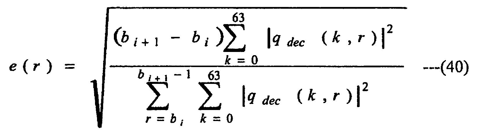
The expression (26) may also be the following expression (41).
When the expression (39) and the expression (40) are used, the temporal envelope information e(r) is information in which the power of each QMF subband sample is normalized by the average power in the SBR envelope, and the square root is extracted. However, the QMF subband sample is a signal vector corresponding to the time index "r" in the QMF domain signal, and is one subsample in the QMF domain. In all the described embodiments, the terminology "time slot" has the same contents as the "QMF subband sample". In this case, the temporal envelope information e(r) is a gain coefficient that should be multiplied by each QMF subband sample, and the same applies to the adjusted temporal envelope information eadj(r). - A speech decoding device 24a (not illustrated) of a
modification 1 of the fourth embodiment physically includes a CPU, a ROM, a RAM, a communication device, and the like, which are not illustrated, and the CPU integrally controls the speech decoding device 24a by loading and executing a predetermined computer program stored in a built-in memory of the speech decoding device 24a such as the ROM into the RAM. The communication device of the speech decoding device 24a receives the encoded multiplexed bit stream output from the speech encoding device 11 or thespeech encoding device 13, and outputs a decoded speech signal to outside the speech decoding device 24a. The speech decoding device 24a functionally includes a bit stream separating unit 2a4 (not illustrated) instead of the bit stream separating unit 2a3 of thespeech decoding device 24, and also includes a temporal envelope supplementary information generating unit 2y (not illustrated), instead of the supplementaryinformation conversion unit 2w. The bit stream separating unit 2a4 separates the multiplexed bit stream into the SBR information and the encoded bit stream. The temporal envelope supplementary information generating unit 2y generates temporal envelope supplementary information based on the information included in the encoded bit stream and the SBR supplementary information. - To generate the temporal envelope supplementary information in a certain SBR envelope, for example, the time width (bi+1-bi) of the SBR envelope, a frame class, a strength parameter of the inverse filter, a noise floor, the amplitude of the high frequency power, a ratio of the high frequency power to the low frequency power, a autocorrelation coefficient or a prediction gain of a result of performing linear prediction analysis in the frequency direction on a low frequency signal represented in the QMF domain, and the like may be used. The temporal envelope supplementary information can be generated by determining K(r) or s(i) based on one or a plurality of values of the parameters. For example, the temporal envelope supplementary information can be generated by determining K(r) or s(i) based on (bi+1-bi) so that K(r) or s(i) is reduced as the time width (bi+1-bi) of the SBR envelope is increased, or K(r) or s(i) is increased as the time width (bi+1-bi) of the SBR envelope is increased. The similar changes may also be made to the first embodiment and the third embodiment.
- A
speech decoding device 24b (seeFIG. 15 ) of amodification 2 of the fourth embodiment physically includes a CPU, a ROM, a RAM, a communication device, and the like, which are not illustrated, and the CPU integrally controls thespeech decoding device 24b by loading and executing a predetermined computer program stored in a built-in memory of thespeech decoding device 24b such as the ROM into the RAM. The communication device of thespeech decoding device 24b receives the encoded multiplexed bit stream output from the speech encoding device 11 or thespeech encoding device 13, and outputs a decoded speech signal to outside thespeech decoding device 24b. Thespeech decoding device 24b, as illustrated inFIG. 15 , includes a primary highfrequency adjusting 1 and a secondary high frequency adjusting unit 2j2 instead of the highunit 2jfrequency adjusting unit 2j. - Here, the primary high
frequency adjusting 1 adjusts a signal in the QMF domain of the high frequency band by performing linear prediction inverse filtering in the temporal direction, the gain adjustment, and noise addition, described in The "HF generation" step and the "HF adjustment" step in SBR in "MPEG4 AAC". At this time, the output signal of the primary high frequency adjusting unit 2j1 corresponds to a signal W2 in the description in "SBR tool" in "ISO/IEC 14496-3:2005", clauses 4.6.18.7.6 of "Assembling HF signals". The linearunit 2jprediction filter unit 2k (or the linear prediction filter unit 2k1) and the temporalenvelope shaping unit 2v shape the temporal envelope of the output signal from the primary high frequency adjusting unit. The secondary high frequency adjusting unit 2j2 performs an addition process of sinusoids in the "HF adjustment" step in SBR in "MPEG4 AAC". The process of the secondary high frequency adjusting unit corresponds to a process of generating a signal Y from the signal W2 in the description in "SBR tool" in "ISO/IEC 14496-3:2005", clauses 4.6.18.7.6 of "Assembling HF signals", in which the signal W2 is replaced with an output signal of the temporalenvelope shaping unit 2v. - In the above description, only the process for adding sinusoids is performed by the secondary high frequency adjusting unit 2j2. However, any one of the processes in the "HF adjustment" step may be performed by the secondary high frequency adjusting unit 2j2. Similar modifications may also be made to the first embodiment, the second embodiment, and the third embodiment. In these cases, the linear prediction filter unit (linear
prediction filter units 2k and 2k1) is included in the first embodiment and the second embodiment, but the temporal envelope shaping unit is not included. Accordingly, an output signal from the primary highfrequency adjusting unit 2j is processed by the linear prediction filter unit, and then an output signal from the linear prediction filter unit is processed by the secondary high frequency adjusting unit 2j2. - In the third embodiment, the temporal
envelope shaping unit 2v is included but the linear prediction filter unit is not included. Accordingly, an output signal from the primary highfrequency adjusting 1 is processed by the temporalunit 2jenvelope shaping unit 2v, and then an output signal from the temporalenvelope shaping unit 2v is processed by the secondary high frequency adjusting unit. - In the speech decoding device (
speech decoding device prediction filter unit 2k and the temporalenvelope shaping unit 2v may be reversed. In other words, an output signal from the highfrequency adjusting unit 2j or the primary highfrequency adjusting 1 may be processed first by the temporalunit 2jenvelope shaping unit 2v, and then an output signal from the temporalenvelope shaping unit 2v may be processed by the linearprediction filter unit 2k. - In addition, only if the temporal envelope supplementary information includes binary control information for indicating whether the process is performed by the linear
prediction filter unit 2k or the temporalenvelope shaping unit 2v, and the control information indicates to perform the process by the linearprediction filter unit 2k or the temporalenvelope shaping unit 2v, the temporal envelope supplementary information may employ a form that further includes at least one of the filer strength parameter K(r), the envelope shape parameter s(i), or X(r) that is a parameter for determining both K(r) and s(i) as information. - A
speech decoding device 24c (seeFIG. 16 ) of amodification 3 of the fourth embodiment physically includes a CPU, a ROM, a RAM, a communication device, and the like, which are not illustrated, and the CPU integrally controls thespeech decoding device 24c by loading and executing a predetermined computer program (such as a computer program for performing processes illustrated in the flowchart ofFIG. 17 ) stored in a built-in memory of thespeech decoding device 24c such as the ROM into the RAM. The communication device of thespeech decoding device 24c receives the encoded multiplexed bit stream and outputs a decoded speech signal to outside thespeech decoding device 24c. As illustrated inFIG. 16 , thespeech decoding device 24c includes a primary high frequency adjusting unit 2j3 and a secondary high frequency adjusting unit 2j4 instead of the highfrequency adjusting unit 2j, and also includes individual signal component adjusting units 2z1, 2z2, and 2z3 instead of the linearprediction filter unit 2k and the temporalenvelope shaping unit 2v (individual signal component adjusting units correspond to the temporal envelope shaping means). - The primary high frequency adjusting unit 2j3 outputs a signal in the QMF domain of the high frequency band as a copy signal component. The primary high frequency adjusting unit 2j3 may output a signal on which at least one of the linear prediction inverse filtering in the temporal direction and the gain adjustment (frequency characteristics adjustment) is performed on the signal in the QMF domain of the high frequency band, by using the SBR supplementary information received from the bit stream separating unit 2a3, as a copy signal component. The primary high frequency adjusting unit 2j3 also generates a noise signal component and a sinusoid signal component by using the SBR supplementary information supplied from the bit stream separating unit 2a3, and outputs each of the copy signal component, the noise signal component, and the sinusoid signal component separately (process at Step Sg1). The noise signal component and the sinusoid signal component may not be generated, depending on the contents of the SBR supplementary information.
- The individual signal component adjusting units 2z1, 2z2, and 2z3 perform processing on each of the plurality of signal components included in the output from the primary high frequency adjusting means (process at Step Sg2). The process with the individual signal component adjusting units 2z1, 2z2, and 2z3 may be linear prediction synthesis filtering in the frequency direction obtained from the filter
strength adjusting unit 2f by using the linear prediction coefficients, similar to that of the linearprediction filter unit 2k (process 1). The process with the individual signal component adjusting units 2z1, 2z2, and 2z3 may also be a process of multiplying each QMF subband sample by a gain coefficient by using the temporal envelope obtained from the envelopeshape adjusting unit 2s, similar to that of the temporalenvelope shaping unit 2v (process 2). The process with the individual signal component adjusting units 2z1, 2z2, and 2z3 may also be a process of performing linear prediction synthesis filtering in the frequency direction on the input signal by using the linear prediction coefficients obtained from the filterstrength adjusting unit 2f similar to that of the linearprediction filter unit 2k, and then multiplying each QMF subband sample by a gain coefficient by using the temporal envelope obtained from the envelopeshape adjusting unit 2s, similar to that of the temporalenvelope shaping unit 2v (process 3). The process with the individual signal component adjusting units 2z1, 2z2, and 2z3 may also be a process of multiplying each QMF subband sample with respect to the input signal by a gain coefficient by using the temporal envelope obtained from the envelopeshape adjusting unit 2s, similar to that of the temporalenvelope shaping unit 2v, and then performing linear prediction synthesis filtering in the frequency direction on the output signal by using the linear prediction coefficients obtained from the filterstrength adjusting unit 2f, similar to that of the linearprediction filter unit 2k (process 4). The individual signal component adjusting units 2z1, 2z2, and 2z3 may not perform the temporal envelope shaping process on the input signal, but may output the input signal as it is (process 5). The process with the individual signal component adjusting units 2z1, 2z2, and 2z3 may include any process for shaping the temporal envelope of the input signal by using a method other than theprocesses 1 to 5 (process 6). The process with the individual signal component adjusting units 2z1, 2z2, and 2z3 may also be a process in which a plurality of processes among theprocesses 1 to 6 are combined in an arbitrary order (process 7). - The processes with the individual signal component adjusting units 2z1, 2z2, and 2z3 may be the same, but the individual signal component adjusting units 2z1, 2z2, and 2z3 may shape the temporal envelope of each of the plurality of signal components included in the output of the primary high frequency adjusting means by different methods. For example, different processes may be performed on the copy signal, the noise signal, and the sinusoid signal, in such a manner that the individual signal component adjusting unit 2z1 performs the
process 2 on the supplied copy signal, the individual signal component adjusting unit 2z2 performs theprocess 3 on the supplied noise signal component, and the individual signal component adjusting unit 2z3 performs the process 5 on the supplied sinusoid signal. In this case, the filterstrength adjusting unit 2f and the envelopeshape adjusting unit 2s may transmit the same linear prediction coefficients and the temporal envelopes to the individual signal component adjusting units 2z1, 2z2, and 2z3, but may also transmit different linear prediction coefficients and the temporal envelopes. It is also possible to transmit the same linear prediction coefficients and the temporal envelopes to at least two of the individual signal component adjusting units 2z1, 2z2, and 2z3. Because at least one of the individual signal component adjusting units 2z1, 2z2, and 2z3 may not perform the temporal envelope shaping process but output the input signal as it is (process 5), the individual signal component adjusting units 2z1, 2z2, and 2z3 perform the temporal envelope process on at least one of the plurality of signal components output from the primary high frequency adjusting unit 2j3 as a whole (if all the individual signal component adjusting units 2z1, 2z2, and 2z3 perform the process 5, the temporal envelope shaping process is not performed on any of the signal components, and the effects of the present invention are not exhibited). - The processes performed by each of the individual signal component adjusting units 2z1, 2z2, and 2z3 may be fixed to one of the
process 1 to the process 7, but may be dynamically determined to perform one of theprocess 1 to the process 7 based on the control information received from outside thespeech decoding device 24c. At this time, it is preferable that the control information is included in the multiplexed bit stream. The control information may be an instruction to perform any one of theprocess 1 to the process 7 in a specific SBR envelope time segment, the encoded frame, or in the other time segment, or may be an instruction to perform any one of theprocess 1 to the process 7 without specifying the time segment of control. - The secondary high frequency adjusting unit 2j4 adds the processed signal components output from the individual signal component adjusting units 2z1, 2z2, and 2z3, and outputs the result to the coefficient adding unit (process at Step Sg3). The secondary high frequency adjusting unit 2j4 may perform at least one of the linear prediction inverse filtering in the temporal direction and gain adjustment (frequency characteristics adjustment) on the copy signal component, by using the SBR supplementary information received from the bit stream separating unit 2a3.
- The individual signal component adjusting units 2z1, 2z2, and 2z3 may operate in cooperation with one another, and generate an output signal at an intermediate stage by adding at least two signal components on which any one of the
processes 1 to 7 is performed, and further performing any one of theprocesses 1 to 7 on the added signal. At this time, the secondary high frequency adjusting unit 2j4 adds the output signal at the intermediate stage and a signal component that has not yet been added to the output signal at the intermediate stage, and outputs the result to the coefficient adding unit. More specifically, it is preferable to generate an output signal at the intermediate stage by performing the process 5 on the copy signal component, applying theprocess 1 on the noise component, adding the two signal components, and further applying theprocess 2 on the added signal. At this time, the secondary high frequency adjusting unit 2j4 adds the sinusoid signal component to the output signal at the intermediate stage, and outputs the result to the coefficient adding unit. - The primary high frequency adjusting unit 2j3 may output any one of a plurality of signal components in a form separated from each other in addition to the three signal components of the copy signal component, the noise signal component, and the sinusoid signal component. In this case, the signal component may be obtained by adding at least two of the copy signal component, the noise signal component, and the sinusoid signal component. The signal component may also be a signal obtained by dividing the band of one of the copy signal component, the noise signal component, and the sinusoid signal. The number of signal components may be other than three, and in this case, the number of the individual signal component adjusting units may be other than three.
- The high frequency signal generated by SBR consists of three elements of the copy signal component obtained by copying from the low frequency band to the high frequency band, the noise signal, and the sinusoid signal. Because the copy signal, the noise signal, and the sinusoid signal have the temporal envelopes different from one another, if the temporal envelope of each of the signal components is shaped by using different methods as the individual signal component adjusting units of the present modification, it is possible to further improve the subjective quality of the decoded signal compared with the other embodiments. In particular, because the noise signal generally has a smooth temporal envelope, and the copy signal has a temporal envelope close to that of the signal in the low frequency band, the temporal envelopes of the copy signal and the noise signal can be independently controlled, by handling them separately and applying different processes thereto. Accordingly, it is effective in improving the subject quality of the decoded signal. More specifically, it is preferable to perform a process of shaping the temporal envelope on the noise signal (
process 3 or process 4), perform a process different from that for the noise signal on the copy signal (process 1 or process 2), and perform the process 5 on the sinusoid signal (in other words, the temporal envelope shaping process is not performed). It is also preferable to perform a shaping process (process 3 or process 4) of the temporal envelope on the noise signal, and perform the process 5 on the copy signal and the sinusoid signal (in other words, the temporal envelope shaping process is not performed). - A
speech encoding device 11b (FIG. 44 ) of amodification 4 of the first embodiment physically includes a CPU, a ROM, a RAM, a communication device, and the like, which are not illustrated, and the CPU integrally controls thespeech encoding device 11b by loading and executing a predetermined computer program stored in a built-in memory of thespeech encoding device 11b such as the ROM into the RAM. The communication device of thespeech encoding device 11b receives a speech signal to be encoded from outside thespeech encoding device 11b, and outputs an encoded multiplexed bit stream to the outside thespeech encoding device 11b. Thespeech encoding device 11b includes a linear prediction analysis unit 1e1 instead of the linearprediction analysis unit 1e of thespeech encoding device 11b, and further includes a timeslot selecting unit 1p. - The time
slot selecting unit 1p receives a signal in the QMF domain from thefrequency transform unit 1a and selects a time slot at which the linear prediction analysis by the linear prediction analysis unit 1e1 is performed. The linear prediction analysis unit 1e1 performs linear prediction analysis on the QMF domain signal in the selected time slot as the linearprediction analysis unit 1e, based on the selection result transmitted from the timeslot selecting unit 1p, to obtain at least one of the high frequency linear prediction coefficients and the low frequency linear prediction coefficient. The filter strengthparameter calculating unit 1f calculates a filter strength parameter by using linear prediction coefficients of the time slot selected by the timeslot selecting unit 1p, obtained by the linear prediction analysis unit 1e1. To select a time slot by the timeslot selecting unit 1p, for example, at least one selection methods using the signal power of the QMF domain signal of the high frequency components, similar to that of a timeslot selecting unit 3 a in adecoding device 21 a of the present modification, which will be described later, may be used. At this time, it is preferable that the QMF domain signal of the high frequency components in the timeslot selecting unit 1p be a frequency component encoded by theSBR encoding unit 1d, among the signals in the QMF domain received from thefrequency transform unit 1a. The time slot selecting method may be at least one of the methods described above, may include at least one method different from those described above, or may be the combination thereof. - A
speech decoding device 21a (seeFIG. 18 ) of themodification 4 of the first embodiment physically includes a CPU, a ROM, a RAM, a communication device, and the like, which are not illustrated, and the CPU integrally controls thespeech decoding device 21a by loading and executing a predetermined computer program (such as a computer program for performing processes illustrated in the flowchart ofFIG. 19 ) stored in a built-in memory of thespeech decoding device 21a such as the ROM into the RAM. The communication device of thespeech decoding device 21 a receives the encoded multiplexed bit stream and outputs a decoded speech signal to outside thespeech decoding device 21a. Thespeech decoding device 21a, as illustrated inFIG. 18 , includes a low frequency linear prediction analysis unit 2d1, a signal change detecting unit 2e1, a high frequency linear prediction analysis unit 2h1, a linear prediction inverse filter unit 2i1, and a linear prediction filter unit 2k3 instead of the low frequency linearprediction analysis unit 2d, the signalchange detecting unit 2e, the high frequency linearprediction analysis unit 2h, the linear predictioninverse filter unit 2i, and the linearprediction filter unit 2k of thespeech decoding device 21, and further includes the timeslot selecting unit 3 a. - The time
slot selecting unit 3a determines whether linear prediction synthesis filtering in the linearprediction filter unit 2k is to be performed on the signal qexp (k, r) in the QMF domain of the high frequency components of the time slot r generated by the highfrequency generating unit 2g, and selects a time slot at which the linear prediction synthesis filtering is performed (process at Step Sh1). The timeslot selecting unit 3 a notifies, of the selection result of the time slot, the low frequency linear prediction analysis unit 2d1, the signal change detecting unit 2e1, the high frequency linear prediction analysis unit 2h1, the linear prediction inverse filter unit 2i1, and the linear prediction filter unit 2k3. The low frequency linear prediction analysis unit 2d1 performs linear prediction analysis on the QMF domain signal in the selected time slot r1, in the same manner as the low frequency linearprediction analysis unit 2d, based on the selection result transmitted from the timeslot selecting unit 3a, to obtain low frequency linear prediction coefficients (process at Step Sh2). The signal change detecting unit 2e1 detects the temporal variation in the QMF domain signal in the selected time slot, as the signalchange detecting unit 2e, based on the selection result transmitted from the timeslot selecting unit 3a, and outputs a detection result T (r1). - The filter
strength adjusting unit 2f performs filter strength adjustment on the low frequency linear prediction coefficients of the time slot selected by the timeslot selecting unit 3a obtained by the low frequency linear prediction analysis unit 2d1, to obtain an adjusted linear prediction coefficients adec (n, r1). The high frequency linear prediction analysis unit 2h1 performs linear prediction analysis in the frequency direction on the QMF domain signal of the high frequency components generated by the highfrequency generating unit 2g for the selected time slot r1, based on the selection result transmitted from the timeslot selecting unit 3a, as the high frequency linearprediction analysis unit 2k, to obtain a high frequency linear prediction coefficients aexp (n, r1) (process at Step Sh3). The linear predictioninverse 1 performs linear prediction inverse filtering, in which aexp (n, r1) are coefficients, in the frequency direction on the signal qexp (k, r) in the QMF domain of the high frequency components of the selected time slot r1, as the linear predictionfilter unit 2iinverse filter unit 2i, based on the selection result transmitted from the timeslot selecting unit 3a (process at Step Sh4). - The linear prediction filter unit 2k3 performs linear prediction synthesis filtering in the frequency direction on a signal qadj(k, r1) in the QMF domain of the high frequency components output from the high
frequency adjusting unit 2j in the selected time slot r1 by using aadj (n, r1) obtained from the filterstrength adjusting unit 2f, as the linearprediction filter unit 2k, based on the selection result transmitted from the timeslot selecting unit 3a (process at Step Sh5). The changes made to the linearprediction filter unit 2k described in themodification 3 may also be made to the linear prediction filter unit 2k3. To select a time slot at which the linear prediction synthesis filtering is performed, for example, the timeslot selecting unit 3 a may select at least one time slot r in which the signal power of the QMF domain signal qexp (k, r) of the high frequency components is greater than a predetermined value Pexp,Th. It is preferable to calculate the signal power of qexp(k,r) according to the following expression.
where M is a value representing a frequency range higher than a lower limit frequency kx of the high frequency components generated by the highfrequency generating unit 2g, and the frequency range of the high frequency components generated by the highfrequency generating unit 2g may be represented as kx≤k<kx+M. The predetermined value Pexp,Th may also be an average value of Pexp(r) of a predetermined time width including the time slot r. The predetermined time width may also be the SBR envelope. - The selection may also be made so as to include a time slot at which the signal power of the QMF domain signal of the high frequency components reaches its peak. The peak signal power may be calculated, for example, by using a moving average value:

of the signal power, and the peak signal power may be the signal power in the QMF domain of the high frequency components of the time slot r at which the result of:
changes from the positive value to the negative value. The moving average value of the signal power,
for example, may be calculated by the following expression.
where c is a predetermined value for defining a range for calculating the average value. The peak signal power may be calculated by the method described above, or may be calculated by a different method. - At least one time slot may be selected from time slots included in a time width t during which the QMF domain signal of the high frequency components transits from a steady state with a small variation of its signal power to a transient state with a large variation of its signal power, and that is smaller than a predetermined value tth. At least one time slot may also be selected from time slots included in a time width t during which the signal power of the QMF domain signal of the high frequency components is changed from a transient state with a large variation to a steady state with a small variation, and that are larger than the predetermined value tth. The time slot r in which |Pexp(r+1)-Pexp(r)| is smaller than a predetermined value (or equal to or smaller than a predetermined value) may be the steady state, and the time slot r in which |Pexp(r+1)-Pexp(r)| is equal to or larger than a predetermined value (or larger than a predetermined value) may be the transient state. The time slot r in which |Pexp,MA(r+1)-Pexp,MA(r)| is smaller than a predetermined value (or equal to or smaller than a predetermined value) may be the steady state, and the time slot r in which |Pexp,MA(r+1)-Pexp,MA(r)| is equal to or larger than a predetermined value (or larger than a predetermined value) may be the transient state. The transient state and the steady state may be defined using the method described above, or may be defined using different methods. The time slot selecting method may be at least one of the methods described above, may include at least one method different from those described above, or may be the combination thereof.
- A
speech encoding device 11c (FIG. 45 ) of a modification 5 of the first embodiment physically includes a CPU, a ROM, a RAM, a communication device, and the like, which are not illustrated, and the CPU integrally controls thespeech encoding device 11c by loading and executing a predetermined computer program stored in a built-in memory of thespeech encoding device 11c such as the ROM into the RAM. The communication device of thespeech encoding device 11c receives a speech signal to be encoded from outside thespeech encoding device 11c, and outputs an encoded multiplexed bit stream to the outside of thespeech encoding device 11c. Thespeech encoding device 11c includes a time slot selecting unit 1p1 and a bit stream multiplexing unit 1g4, instead of the timeslot selecting unit 1p and the bit stream multiplexing unit 1g of thespeech encoding device 11b of themodification 4. - The time slot selecting unit 1p1 selects a time slot as the time
slot selecting unit 1p described in themodification 4 of the first embodiment, and transmits time slot selection information to the bit stream multiplexing unit 1g4. The bit stream multiplexing unit 1g4 multiplexes the encoded bit stream calculated by the corecodec encoding unit 1c, the SBR supplementary information calculated by theSBR encoding unit 1d, and the filter strength parameter calculated by the filter strengthparameter calculating unit 1f as the bit stream multiplexing unit 1g, also multiplexes the time slot selection information received from the time slot selecting unit 1p1, and outputs the multiplexed bit stream through the communication device of thespeech encoding device 11c. The time slot selection information is time slot selection information received by a time slot selecting unit 3a1 in aspeech decoding device 21b, which will be describe later, and for example, an index r1 of a time slot to be selected may be included. The time slot selection information may also be a parameter used in the time slot selecting method of the time slot selecting unit 3a1. Thespeech decoding device 21b (seeFIG. 20 ) of the modification 5 of the first embodiment physically includes a CPU, a ROM, a RAM, a communication device, and the like, which are not illustrated, and the CPU integrally controls thespeech decoding device 21 b by loading and executing a predetermined computer program (such as a computer program for performing processes illustrated in the flowchart ofFIG. 21 ) stored in a built-in memory of thespeech decoding device 21b such as the ROM into the RAM. The communication device of thespeech decoding device 21b receives the encoded multiplexed bit stream and outputs a decoded speech signal to outside thespeech decoding device 21b. - The
speech decoding device 21b, as illustrated inFIG. 20 , includes a bit stream separating unit 2a5 and the time slot selecting unit 3a1 instead of the bitstream separating unit 2a and the timeslot selecting unit 3a of thespeech decoding device 21a of themodification 4, and time slot selection information is supplied to the time slot selecting unit 3a1. The bit stream separating unit 2a5 separates the multiplexed bit stream into the filter strength parameter, the SBR supplementary information, and the encoded bit stream as the bitstream separating unit 2a, and further separates the time slot selection information. The time slot selecting unit 3a1 selects a time slot based on the time slot selection information transmitted from the bit stream separating unit 2a5 (process at Step Si1). The time slot selection information is information used for selecting a time slot, and for example, may include the index r1 of the time slot to be selected. The time slot selection information may also be a parameter, for example, used in the time slot selecting method described in themodification 4. In this case, although not illustrated, the QMF domain signal of the high frequency components generated by the high frequencysignal generating unit 2g may be supplied to the time slot selecting unit 3a1, in addition to the time slot selection information. The parameter may also be a predetermined value (such as Pexp,Th and tTh) used for selecting the time slot. - A speech encoding device 11d (not illustrated) of a modification 6 of the first embodiment physically includes a CPU, a ROM, a RAM, a communication device, and the like, which are not illustrated, and the CPU integrally controls the speech encoding device 11d by loading and executing a predetermined computer program stored in a built-in memory of the speech encoding device 11d such as the ROM into the RAM. The communication device of the speech encoding device 11d receives a speech signal to be encoded from outside the speech encoding device 11d, and outputs an encoded multiplexed bit stream to the outside of the speech encoding device 11d. The speech encoding device 11d includes a short-term power calculating unit lit, which is not illustrated, instead of the short-term power calculating unit is of the
speech encoding device 11a of themodification 1, and further includes a time slot selecting unit 1p2. - The time slot selecting unit 1p2 receives a signal in the QMF domain from the
frequency transform unit 1a, and selects a time slot corresponding to the time segment at which the short-term power calculation process is performed by the short-termpower calculating unit 1i. The short-term power calculating unit 1i1 calculates the short-term power of a time segment corresponding to the selected time slot based on the selection result transmitted from the time slot selecting unit 1p2, as the short-termpower calculating unit 1i of thespeech encoding device 11a of themodification 1. - A speech encoding device 11e (not illustrated) of a modification 7 of the first embodiment physically includes a CPU, a ROM, a RAM, a communication device, and the like, which are not illustrated, and the CPU integrally controls the speech encoding device 11e by loading and executing a predetermined computer program stored in a built-in memory of the speech encoding device 11e such as the ROM into the RAM. The communication device of the speech encoding device 11e receives a speech signal to be encoded from outside the speech encoding device 11e, and outputs an encoded multiplexed bit stream to the outside of the speech encoding device 11e. The speech encoding device 11e includes a time slot selecting unit 1p3, which is not illustrated, instead of the time slot selecting unit 1p2 of the speech encoding device 11d of the modification 6. The speech encoding device 11e also includes a bit stream multiplexing unit that further receives an output from the time slot selecting unit 1p3, instead of the bit stream multiplexing unit 1g1. The time slot selecting unit 1p3 selects a time slot as the time slot selecting unit 1p2 described in the modification 6 of the first embodiment, and transmits time slot selection information to the bit stream multiplexing unit.
- A speech encoding device (not illustrated) of a modification 8 of the first embodiment physically includes a CPU, a ROM, a RAM, a communication device, and the like, which are not illustrated, and the CPU integrally controls the speech encoding device of the modification 8 by loading and executing a predetermined computer program stored in a built-in memory of the speech encoding device of the modification 8 such as the ROM into the RAM. The communication device of the speech encoding device of the modification 8 receives a speech signal to be encoded from outside the speech encoding device, and outputs an encoded multiplexed bit stream to the outside of the speech encoding device. The speech encoding device of the modification 8 further includes the time
slot selecting unit 1p in addition to those of the speech encoding device described in themodification 2. - A speech decoding device (not illustrated) of the modification 8 of the first embodiment physically includes a CPU, a ROM, a RAM, a communication device, and the like, which are not illustrated, and the CPU integrally controls the speech decoding device of the modification 8 by loading and executing a predetermined computer program stored in a built-in memory of the speech decoding device of the modification 8 such as the ROM into the RAM. The communication device of the speech decoding device of the modification 8 receives the encoded multiplexed bit stream, and outputs a decoded speech signal to the outside of the speech decoding device. The speech decoding device of the modification 8 further includes the low frequency linear prediction analysis unit 2d1, the signal change detecting unit 2e1, the high frequency linear prediction analysis unit 2h1, the linear prediction inverse filter unit 2i1, and the linear prediction filter unit 2k3, instead of the low frequency linear
prediction analysis unit 2d, the signalchange detecting unit 2e, the high frequency linearprediction analysis unit 2h, the linear predictioninverse filter unit 2i, and the linearprediction filter unit 2k of the speech decoding device described in themodification 2, and further includes the timeslot selecting unit 3a. - A speech encoding device (not illustrated) of a modification 9 of the first embodiment physically includes a CPU, a ROM, a RAM, a communication device, and the like, which are not illustrated, and the CPU integrally controls the speech encoding device of the modification 9 by loading and executing a predetermined computer program stored in a built-in memory of the speech encoding device of the modification 9 such as the ROM into the RAM. The communication device of the speech encoding device of the modification 9 receives a speech signal to be encoded from outside the speech encoding device, and outputs an encoded multiplexed bit stream to the outside of the speech encoding device. The speech encoding device of the modification 9 includes the time slot selecting unit 1p1 instead of the time
slot selecting unit 1p of the speech encoding device described in the modification 8. The speech encoding device of the modification 9 further includes a bit stream multiplexing unit that receives an output from the time slot selecting unit 1p1 in addition to the input supplied to the bit stream multiplexing unit described in the modification 8, instead of the bit stream multiplexing unit described in the modification 8. - A speech decoding device (not illustrated) of the modification 9 of the first embodiment physically includes a CPU, a ROM, a RAM, a communication device, and the like, which are not illustrated, and the CPU integrally controls the speech decoding device of the modification 9 by loading and executing a predetermined computer program stored in a built-in memory of the speech decoding device of the modification 9 such as the ROM into the RAM. The communication device of the speech decoding device of the modification 9 receives the encoded multiplexed bit stream, and outputs a decoded speech signal to the outside of the speech decoding device. The speech decoding device of the modification 9 includes the time slot selecting unit 3a1 instead of the time
slot selecting unit 3a of the speech decoding device described in the modification 8. The speech decoding device of the modification 9 further includes a bit stream separating unit that separates aD (n, r) described in themodification 2 instead of the filter strength parameter of the bit stream separating unit 2a5, instead of the bitstream separating unit 2a. - A
speech encoding device 12a (FIG. 46 ) of amodification 1 of the second embodiment physically includes a CPU, a ROM, a RAM, a communication device, and the like, which are not illustrated, and the CPU integrally controls thespeech encoding device 12a by loading and executing a predetermined computer program stored in a built-in memory of thespeech encoding device 12a such as the ROM into the RAM. The communication device of thespeech encoding device 12a receives a speech signal to be encoded from outside thespeech encoding device 12a, and outputs an encoded multiplexed bit stream to the outside of thespeech encoding device 12a.. Thespeech encoding device 12a includes the linear prediction analysis unit 1e1 instead of the linearprediction analysis unit 1e of thespeech encoding device 12, and further includes the timeslot selecting unit 1p. - A
speech decoding device 22a (seeFIG. 22 ) of themodification 1 of the second embodiment physically includes a CPU, a ROM, a RAM, a communication device, and the like, which are not illustrated, and the CPU integrally controls thespeech decoding device 22a by loading and executing a predetermined computer program (such as a computer program for performing processes illustrated in the flowchart ofFIG. 23 ) stored in a built-in memory of thespeech decoding device 22a such as the ROM into the RAM. The communication device of thespeech decoding device 22a receives the encoded multiplexed bit stream, and outputs a decoded speech signal to the outside of thespeech decoding device 22a. Thespeech decoding device 22a, as illustrated inFIG 22 , includes the low frequency linear prediction analysis unit 2d1, the signal change detecting unit 2e1, the high frequency linear prediction analysis unit 2h1, the linear prediction inverse filter unit 2i1, a linear prediction filter unit 2k2, and a linear prediction interpolation/extrapolation unit 2p1, instead of the high frequency linearprediction analysis unit 2h, the linear predictioninverse filter unit 2i, the linear prediction filter unit 2k1, and the linear prediction interpolation/extrapolation unit 2p of thespeech decoding device 22 of the second embodiment, and further includes the timeslot selecting unit 3a. - The time
slot selecting unit 3a notifies, of the selection result of the time slot, the high frequency linear prediction analysis unit 2h1, the linear prediction inverse filter unit 2i1, the linear prediction filter unit 2k2, and the linear prediction coefficient interpolation/extrapolation unit 2p1. The linear prediction coefficient interpolation/extrapolation unit 2p1 obtains aH(n, r) corresponding to the time slot r1 that is the selected time slot and of which linear prediction coefficients are not transmitted by interpolation or extrapolation, as the linear prediction coefficient interpolation/extrapolation unit 2p, based on the selection result transmitted from the timeslot selecting unit 3a (process at Step Sj1). The linear prediction filter unit 2k2 performs linear prediction synthesis filtering in the frequency direction on qadj (n, r1) output from the highfrequency adjusting unit 2j for the selected time slot r1 by using aH (n, r1) being interpolated or extrapolated and obtained from the linear prediction coefficient interpolation/extrapolation unit 2p1, as the linear prediction filter unit 2k1 (process at Step Sj2), based on the selection result transmitted from the timeslot selecting unit 3a. The changes made to the linearprediction filter unit 2k described in themodification 3 of the first embodiment may also be made to the linear prediction filter unit 2k2. - A
speech encoding device 12b (FIG. 47 ) of amodification 2 of the second embodiment physically includes a CPU, a ROM, a RAM, a communication device, and the like, which are not illustrated, and the CPU integrally controls thespeech encoding device 11b by loading and executing a predetermined computer program stored in a built-in memory of thespeech encoding device 12b such as the ROM into the RAM. The communication device of thespeech encoding device 12b receives a speech signal to be encoded from outside thespeech encoding device 12b, and outputs an encoded multiplexed bit stream to the outside of thespeech encoding device 12b. Thespeech encoding device 12b includes the time slot selecting unit 1p1 and a bit stream multiplexing unit 1g5 instead of the timeslot selecting unit 1p and the bit stream multiplexing unit 1g2 of thespeech encoding device 12a of themodification 1. The bit stream multiplexing unit 1g5 multiplexes the encoded bit stream calculated by the corecodec encoding unit 1c, the SBR supplementary information calculated by theSBR encoding unit 1d, and indices of the time slots corresponding to the quantized linear prediction coefficients received from the linear predictioncoefficient quantizing unit 1k as the bit stream multiplexing unit 1g2, further multiplexes the time slot selection information received from the time slot selecting unit 1p1, and outputs the multiplexed bit stream through the communication device of thespeech encoding device 12b. - A
speech decoding device 22b (seeFIG. 24 ) of themodification 2 of the second embodiment physically includes a CPU, a ROM, a RAM, a communication device, and the like, which are not illustrated, and the CPU integrally controls thespeech decoding device 22b by loading and executing a predetermined computer program (such as a computer program for performing processes illustrated in the flowchart ofFIG. 25 ) stored in a built-in memory of thespeech decoding device 22b such as the ROM into the RAM. The communication device of thespeech decoding device 22b receives the encoded multiplexed bit stream, and outputs a decoded speech signal to the outside of thespeech decoding device 22b. Thespeech decoding device 22b, as illustrated inFIG. 24 , includes a bit stream separating unit 2a6 and the time slot selecting unit 3a1 instead of the bit stream separating unit 2a1 and the timeslot selecting unit 3 a of thespeech decoding device 22a described in themodification 1, and time slot selection information is supplied to the time slot selecting unit 3a1. The bit stream separating unit 2a6 separates the multiplexed bit stream into aH (n, ri) being quantized, the index ri of the corresponding time slot, the SBR supplementary information, and the encoded bit stream as the bit stream separating unit 2a1, and further separates the time slot selection information. - (
Modification 4 of Third Embodiment)
described in themodification 1 of the third embodiment may be an average value of e (r) in the SBR envelope, or may be a value defined in some other manner. - As described in the
modification 3 of the third embodiment, it is preferable that the envelopeshape adjusting unit 2s control eadj(r) by using a predetermined value eadj,Th(r), considering that the adjusted temporal envelope eadj(r) is a gain coefficient multiplied by the QMF subband sample, for example, as the expression (28) and the expressions (37) and (38).
- A speech encoding device 14 (
FIG. 48 ) of the fourth embodiment physically includes a CPU, a ROM, a RAM, a communication device, and the like, which are not illustrated, and the CPU integrally controls thespeech encoding device 14 by loading and executing a predetermined computer program stored in a built-in memory of thespeech encoding device 14 such as the ROM into the RAM. The communication device of thespeech encoding device 14 receives a speech signal to be encoded from outside thespeech encoding device 14, and outputs an encoded multiplexed bit stream to the outside of thespeech encoding device 14. Thespeech encoding device 14 includes a bit stream multiplexing unit 1g7 instead of the bit stream multiplexing unit 1g of thespeech encoding device 11b of themodification 4 of the first embodiment, and further includes the temporalenvelope calculating unit 1m and the envelopeparameter calculating unit 1n of thespeech encoding device 13. - The bit stream multiplexing unit 1g7 multiplexes the encoded bit stream calculated by the core
codec encoding unit 1c and the SBR supplementary information calculated by theSBR encoding unit 1d as the bit stream multiplexing unit 1g, converts the filter strength parameter calculated by the filter strength parameter calculating unit and the envelope shape parameter calculated by the envelope shapeparameter calculating unit 1n into the temporal envelope supplementary information, multiplexes them, and outputs the multiplexed bit stream (encoded multiplexed bit stream) through the communication device of thespeech encoding device 14. - A
speech encoding device 14a (FIG. 49 ) of amodification 4 of the fourth embodiment physically includes a CPU, a ROM, a RAM, a communication device, and the like, which are not illustrated, and the CPU integrally controls thespeech encoding device 14a by loading and executing a predetermined computer program stored in a built-in memory of thespeech encoding device 14a such as the ROM into the RAM. The communication device of thespeech encoding device 14a receives a speech signal to be encoded from outside thespeech encoding device 14a, and outputs an encoded multiplexed bit stream to the outside of thespeech encoding device 14a. Thespeech encoding device 14a includes the linearprediction 1 instead of the linearanalysis unit 1eprediction analysis unit 1e of thespeech encoding device 14 of the fourth embodiment, and further includes the timeslot selecting unit 1p. - A
speech decoding device 24d (seeFIG. 26 ) of themodification 4 of the fourth embodiment physically includes a CPU, a ROM, a RAM, a communication device, and the like, which are not illustrated, and the CPU integrally controls thespeech decoding device 24d by loading and executing a predetermined computer program (such as a computer program for performing processes illustrated in the flowchart ofFIG. 27 ) stored in a built-in memory of thespeech decoding device 24d such as the ROM into the RAM. The communication device of thespeech decoding device 24d receives the encoded multiplexed bit stream, and outputs a decoded speech signal to the outside of thespeech decoding device 24d. Thespeech decoding device 24d, as illustrated inFIG. 26 , includes the low frequency linear prediction analysis unit 2d1, the signal change detecting unit 2e1, the high frequency linear prediction analysis unit 2h1, the linear prediction inverse filter unit 2i1, and the linear prediction filter unit 2k3 instead of the low frequency linearprediction analysis unit 2d, the signalchange detecting unit 2e, the high frequency linearprediction analysis unit 2h, the linear predictioninverse filter unit 2i, and the linearprediction filter unit 2k of thespeech decoding device 24, and further includes the time slot selecting unit .3a. The temporalenvelope shaping unit 2v shapes the signal in the QMF domain obtained from the linear prediction filter unit 2k3 by using the temporal envelope information obtained from the envelopeshape adjusting unit 2s, as the temporalenvelope shaping unit 2v of the third embodiment, the fourth embodiment, and the modifications thereof (process at Step Sk1). - A
speech decoding device 24e (seeFIG 28 ) of a modification 5 of the fourth embodiment physically includes a CPU, a ROM, a RAM, a communication device, and the like, which are not illustrated, and the CPU integrally controls thespeech decoding device 24e by loading and executing a predetermined computer program (such as a computer program for performing processes illustrated in the flowchart ofFIG. 29 ) stored in a built-in memory of thespeech decoding device 24e such as the ROM into the RAM. The communication device of thespeech decoding device 24e receives the encoded multiplexed bit stream, and outputs a decoded speech signal to the outside of thespeech decoding device 24e. In the modification 5, as illustrated inFIG. 28 , thespeech decoding device 24e omits the high frequency linear prediction analysis unit 2h1 and the linear prediction inverse filter unit 2i1 of thespeech decoding device 24d described in themodification 4 that can be omitted throughout the fourth embodiment as the first embodiment, and includes a time slot selecting unit 3a2 and a temporal envelope shaping unit 2v1 instead of the timeslot selecting unit 3a and the temporalenvelope shaping unit 2v of thespeech decoding device 24d. Thespeech decoding device 24e also changes the order of the linear prediction synthesis filtering performed by the linear prediction filter unit 2k3 and the temporal envelope shaping process performed by the temporal envelope shaping unit 2v1 whose processing order is interchangeable throughout the fourth embodiment. - The temporal envelope shaping unit 2v1 shapes qadj (k, r) obtained from the high
frequency adjusting unit 2j by using eadj(r) obtained from the envelopeshape adjusting unit 2s, as the temporalenvelope shaping unit 2v, and obtains a signal qenvadj (k, r) in the QMF domain in which the temporal envelope is shaped. The temporal envelope shaping unit 2v1 also notifies the time slot selecting unit 3a2 of parameters obtained when the temporal envelope is being shaped, or parameters calculated by at least using the parameters obtained when the temporal envelope is being shaped as time slot selection information. The time slot selection information may be e(r) of the expression (22) or the expression (40), or |e(r)|2 to which the square root operation is not applied during the calculation process. A plurality of time slot sections (such as SBR envelopes)
may also be used, and the expression (24) that is the average value thereof

- The time slot selection information may also be eexp(r) of the expression (26) and the expression (41), or |eexp(r)|2 to which the square root operation is not applied during the calculation process. A plurality of time slot segments (such as SBR envelopes)

and the average value thereof
may also be used as the time slot selection information. It is noted that:

The time slot selection information may also be eadj(r) of the expression (23), the expression (35) or the expression (36), or may be |eadj(r)|2 to which the square root operation is not applied during the calculation process. A plurality of time slot segments (such as SBR envelopes)
and the average value thereof
may also be used as the time slot selection information. It is noted that:

The time slot selection information may also be eadj,scaled(r) of the expression (37), or may be |eadj, scaled(r)|2 to which the square root operation is not applied during the calculation process. In a plurality of time slot segments (such as SBR envelopes)
and the average value thereof
may also be used as the time slot selection information. It is noted that:

The time slot selection information may also be a signal power Penvadj(r) of the time slot r of the QMF domain signal corresponding to the high frequency components in which the temporal envelope is shaped or a signal amplitude value thereof to which the square root operation is applied
In a plurality of time slot segments (such as SBR envelopes)
and the average value thereof
may also be used as the time slot selection information. It is noted that:
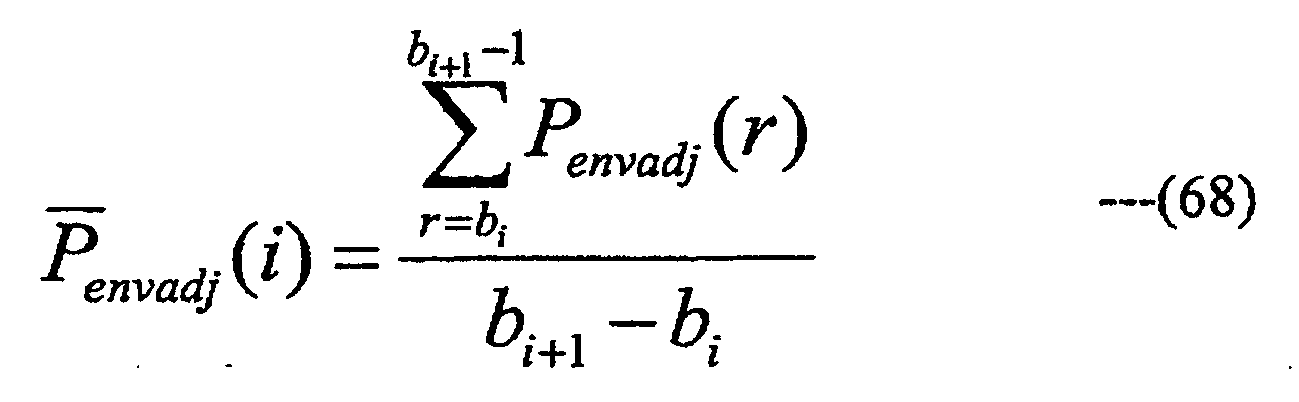
M is a value representing a frequency range higher than that of the lower limit frequency kx of the high frequency components generated by the highfrequency generating unit 2g, and the frequency range of the high frequency components generated by the highfrequency generating unit 2g may also be represented as kx≤k<kx+M. - The time slot selecting unit 3a2 selects time slots at which the linear prediction synthesis filtering by the linear
prediction filter unit 2k is performed, by determining whether linear prediction synthesis filtering is performed on the signal qenvadj (k, r) in the QMF domain of the high frequency components of the time slot r in which the temporal envelope is shaped by the temporal envelope shaping unit 2v1, based on the time slot selection information transmitted from the temporal envelope shaping unit 2v1 (process at Step Sp1). - To select time slots at which the linear prediction synthesis filtering is performed by the time slot selecting unit 3a2 in the present modification, at least one time slot r in which a parameter u(r) included in the time slot selection information transmitted from the temporal envelope shaping unit 2v1 is larger than a predetermined value uTh may be selected, or at least one time slot r in which u(r) is equal to or larger than a predetermined value uThmay be selected. u(r) may include at least one of e(r), |e(r)|2, eexp(r), |eexp(r)|2, eadj(r), |eadj(r)|2, eadj,scaled(r), |eadj,ScaJed(r)|2, and Penvadj(r), described above, and;

and uTh may include at least one of;
uTh may also be an average value of u(r) of a predetermined time width (such as SBR envelope) including the time slot r. The selection may also be made so that time slots at which u(r) reaches its peaks are included. The peaks of u(r) may be calculated as calculating the peaks of the signal power in the QMF domain signal of the high frequency components in themodification 4 of the first embodiment. The steady state and the transient state in themodification 4 of the first embodiment may be determined similar to those of themodification 4 of the first embodiment by using u(r), and time slots may be selected based on this. The time slot selecting method may be at least one of the methods described above, may include at least one method different from those described above, or may be the combination thereof. - A
speech decoding device 24f (seeFIG. 30 ) of a modification 6 of the fourth embodiment physically includes a CPU, a ROM, a RAM, a communication device, and the like, which are not illustrated, and the CPU integrally controls thespeech decoding device 24f by loading and executing a predetermined computer program (such as a computer program for performing processes illustrated in the flowchart ofFIG. 29 ) stored in a built-in memory of thespeech decoding device 24e such as the ROM into the RAM. The communication device of thespeech decoding device 24f receives the encoded multiplexed bit stream and outputs a decoded speech signal to outside thespeech decoding device 24f. In the modification 6, as illustrated inFIG. 30 , thespeech decoding device 24f omits the signal change detecting unit 2e1, the high frequency linear prediction analysis unit 2h1, and the linear predictioninverse 1 of thefilter unit 2ispeech decoding device 24d described in themodification 4 that can be omitted throughout the fourth embodiment as the first embodiment, and includes the time slot selecting unit 3a2 and the temporal envelope shaping unit 2v1 instead of the timeslot selecting unit 3a and the temporalenvelope shaping unit 2v of thespeech decoding device 24d. Thespeech decoding device 24f also changes the order of the linear prediction synthesis filtering performed by the linear prediction filter unit 2k3 and the temporal envelope shaping process performed by the temporal envelope shaping unit 2v1 whose processing order is interchangeable throughout the fourth embodiment. - The time slot selecting unit 3a2 determines whether linear prediction synthesis filtering is performed by the linear prediction filter unit 2k3, on the signal qenvadj (k, r) in the QMF domain of the high frequency components of the time slots r in which the temporal envelope is shaped by the temporal envelope shaping unit 2v1, based on the time slot selection information transmitted from the temporal envelope shaping unit 2v1, selects time slots at which the linear prediction synthesis filtering is performed, and notifies, of the selected time slots, the low frequency linear prediction analysis unit 2d1 and the linear prediction filter unit 2k3.
- A
speech encoding device 14b (FIG. 50 ) of a modification 7 of the fourth embodiment physically includes a CPU, a ROM, a RAM, a communication device, and the like, which are not illustrated, and the CPU integrally controls thespeech encoding device 14b by loading and executing a predetermined computer program stored in a built-in memory of thespeech encoding device 14b such as the ROM into the RAM. The communication device of thespeech encoding device 14b receives a speech signal to be encoded from outside thespeech encoding device 14b, and outputs an encoded multiplexed bit stream to the outside of thespeech encoding device 14b. Thespeech encoding device 14b includes a bit stream multiplexing unit 1g6 and the time slot selecting unit 1p1 instead of the bit stream multiplexing unit 1g7 and the timeslot selecting unit 1p of thespeech encoding device 14a of themodification 4. - The bit stream multiplexing unit 1g6 multiplexes the encoded bit stream calculated by the core
codec encoding unit 1c, the SBR supplementary information calculated by theSBR encoding unit 1d, and the temporal envelope supplementary information in which the filter strength parameter calculated by the filter strength parameter calculating unit and the envelope shape parameter calculated by the envelope shapeparameter calculating unit 1n are converted, also multiplexes the time slot selection information received from the time slot selecting unit 1p1, and outputs the multiplexed bit stream (encoded multiplexed bit stream) through the communication device of thespeech encoding device 14b. - A
speech decoding device 24g (seeFIG. 31 ) of the modification 7 of the fourth embodiment physically includes a CPU, a ROM, a RAM, a communication device, and the like, which are not illustrated, and the CPU integrally controls thespeech decoding device 24g by loading and executing a predetermined computer program (such as a computer program for performing processes illustrated in the flowchart ofFIG 32 ) stored in a built-in memory of thespeech decoding device 24g such as the ROM into the RAM. The communication device of thespeech decoding device 24g receives the encoded multiplexed bit stream and outputs a decoded speech signal to outside thespeech decoding device 24g. Thespeech decoding device 24g includes a bit stream separating unit 2a7 and the time slot selecting unit 3al instead of the bit stream separating unit 2a3 and the timeslot selecting unit 3a of thespeech decoding device 2d described in themodification 4. - The bit stream separating unit 2a7 separates the multiplexed bit stream supplied through the communication device of the
speech decoding device 24g into the temporal envelope supplementary information, the SBR supplementary information, and the encoded bit stream, as the bit stream separating unit 2a3, and further separates the time slot selection information. - A
speech decoding device 24h (seeFIG 33 ) of a modification 8 of the fourth embodiment physically includes a CPU, a ROM, a RAM, a communication device, and the like, which are not illustrated, and the CPU integrally controls thespeech decoding device 24h by loading and executing a predetermined computer program (such as a computer program for performing processes illustrated in the flowchart ofFIG. 34 ) stored in a built-in memory of thespeech decoding device 24h such as the ROM into the RAM. The communication device of thespeech decoding device 24h receives the encoded multiplexed bit stream and outputs a decoded speech signal to outside thespeech decoding device 24h. Thespeech decoding device 24h, as illustrated inFIG. 33 , includes the low frequency linear prediction analysis unit 2d1, the signal change detecting unit 2e1, the high frequency linear prediction analysis unit 2h1, the linear prediction inverse filter unit 2i1, and the linear prediction filter unit 2k3 instead of the low frequency linearprediction analysis unit 2d, the signalchange detecting unit 2e, the high frequency linearprediction analysis unit 2h, the linear predictioninverse filter unit 2i, and the linearprediction filter unit 2k of thespeech decoding device 24b of themodification 2, and further includes the timeslot selecting unit 3a. The primary highfrequency adjusting 1 performs at least one of the processes in the "HF Adjustment" step in SBR in "MPEG-4 AAC", as the primary highunit 2jfrequency adjusting unit 2j 1 of themodification 2 of the fourth embodiment (process at Step Sm1). The secondary high frequency adjusting unit 2j2 performs at least one of the processes in the "HF Adjustment" step in SBR in "MPEG-4 AAC", as the secondary high frequency adjusting unit 2j2 of themodification 2 of the fourth embodiment (process at Step Sm2). It is preferable that the process performed by the secondary high frequency adjusting unit 2j2 be a process not performed by the primary highfrequency adjusting 1 among the processes in the "HF Adjustment" step in SBR in "MPEG-4 AAC".unit 2j - A
speech decoding device 24i (seeFIG. 35 ) of the modification 9 of the fourth embodiment physically includes a CPU, a ROM, a RAM, a communication device, and the like, which are not illustrated, and the CPU integrally controls thespeech decoding device 24i by loading and executing a predetermined computer program (such as a computer program for performing processes illustrated in the flowchart ofFIG. 36 ) stored in a built-in memory of thespeech decoding device 24i such as the ROM into the RAM. The communication device of thespeech decoding device 24i receives the encoded multiplexed bit stream and outputs a decoded speech signal to outside thespeech decoding device 24i. Thespeech decoding device 24i, as illustrated inFIG 35 , omits the high frequency linear prediction analysis unit 2h1 and the linear prediction inverse filter unit 2i1 of thespeech decoding device 24h of the modification 8 that can be omitted throughout the fourth embodiment as the first embodiment, and includes the temporal envelope shaping unit 2v1 and the time slot selecting unit 3a2 instead of the temporalenvelope shaping unit 2v and the timeslot selecting unit 3a of thespeech decoding device 24h of the modification 8. Thespeech decoding device 24i also changes the order of the linear prediction synthesis filtering performed by the linear prediction filter unit 2k3 and the temporal envelope shaping process performed by the temporal envelope shaping unit 2v1 whose processing order is interchangeable throughout the fourth embodiment. - A
speech decoding device 24j (seeFIG. 37 ) of amodification 10 of the fourth embodiment physically includes a CPU, a ROM, a RAM, a communication device, and the like, which are not illustrated, and the CPU integrally controls thespeech decoding device 24j by loading and executing a predetermined computer program (such as a computer program for performing processes illustrated in the flowchart ofFIG. 36 ) stored in a built-in memory of thespeech decoding device 24j such as the ROM into the RAM. The communication device of thespeech decoding device 24j receives the encoded multiplexed bit stream and outputs a decoded speech signal to outside thespeech decoding device 24j. Thespeech decoding device 24j, as illustrated inFIG. 37 , omits the signal change detecting unit 2e1, the high frequency linear prediction analysis unit 2h1, and the linear prediction inverse filter unit 2i1 of thespeech decoding device 24h of the modification 8 that can be omitted throughout the fourth embodiment as the first embodiment, and includes the temporal envelope shaping unit 2v1 and the time slot selecting unit 3a2 instead of the temporalenvelope shaping unit 2v and the timeslot selecting unit 3a of thespeech decoding device 24h of the modification 8. The order of the linear prediction synthesis filtering performed by the linear prediction filter unit 2k3 and the temporal envelope shaping process performed by the temporal envelope shaping unit 2v1 is changed, whose processing order is interchangeable throughout the fourth embodiment. - A
speech decoding device 24k (seeFIG. 38 ) of a modification 11 of the fourth embodiment physically includes a CPU, a ROM, a RAM, a communication device, and the like, which are not illustrated, and the CPU integrally controls thespeech decoding device 24k by loading and executing a predetermined computer program (such as a computer program for performing processes illustrated in the flowchart ofFIG. 39 ) stored in a built-in memory of thespeech decoding device 24k such as the ROM into the RAM. The communication device of thespeech decoding device 24k receives the encoded multiplexed bit stream and outputs a decoded speech signal to outside thespeech decoding device 24k. Thespeech decoding device 24k, as illustrated inFIG 38 , includes the bit stream separating unit 2a7 and the time slot selecting unit 3a1 instead of the bit stream separating unit 2a3 and the timeslot selecting unit 3a of thespeech decoding device 24h of the modification 8. - A speech decoding device 24q (see
FIG. 40 ) of amodification 12 of the fourth embodiment physically includes a CPU, a ROM, a RAM, a communication device, and the like, which are not illustrated, and the CPU integrally controls the speech decoding device 24q by loading and executing a predetermined computer program (such as a computer program for performing processes illustrated in the flowchart ofFIG. 41 ) stored in a built-in memory of the speech decoding device 24q such as the ROM into the RAM. The communication device of the speech decoding device 24q receives the encoded multiplexed bit stream and outputs a decoded speech signal to outside the speech decoding device 24q. The speech decoding device 24q, as illustrated inFIG. 40 , includes the low frequency linear prediction analysis unit 2d1, the signal change detecting unit 2e1, the high frequency linear prediction analysis unit 2h1, the linear prediction inverse filter unit 2i1, and individual signal component adjusting units 2z4, 2z5, and 2z6 (individual signal component adjusting units correspond to the temporal envelope shaping means) instead of the low frequency linearprediction analysis unit 2d, the signalchange detecting unit 2e, the high frequency linearprediction analysis unit 2h, the linear predictioninverse filter unit 2i, and the individual signal component adjusting units 2z1, 2z2, and 2z3 of thespeech decoding device 24c of themodification 3, and further includes the timeslot selecting unit 3a. - At least one of the individual signal component adjusting units 2z4, 2z5, and 2z6 performs processing on the QMF domain signal of the selected time slot, for the signal component included in the output of the primary high frequency adjusting means, as the individual signal component adjusting units 2z1, 2z2, and 2z3, based on the selection result transmitted from the time
slot selecting unit 3a (process at Step Sn1). It is preferable that the process using the time slot selection information include at least one process including the linear prediction synthesis filtering in the frequency direction, among the processes of the individual signal component adjusting units 2z1, 2z2, and 2z3 described in themodification 3 of the fourth embodiment. - The processes performed by the individual signal component adjusting units 2z4, 2z5, and 2z6 may be the same as the processes performed by the individual signal component adjusting units 2z1, 2z2, and 2z3 described in the
modification 3 of the fourth embodiment, but the individual signal component adjusting units 2z4, 2z5, and 2z6 may shape the temporal envelope of each of the plurality of signal components included in the output of the primary high frequency adjusting means by different methods (if all the individual signal component adjusting units 2z4, 2z5, and 2z6 do not perform processing based on the selection result transmitted from the timeslot selecting unit 3a, it is the same as themodification 3 of the fourth embodiment of the present invention). - All the selection results of the time slot transmitted to the individual signal component adjusting units 2z4, 2z5, and 2z6 from the time
slot selecting unit 3 a need not be the same, and all or a part thereof may be different. - In
FIG. 40 , the result of the time slot selection is transmitted to the individual signal component adjusting units 2z4, 2z5, and 2z6 from one timeslot selecting unit 3a. However, it is possible to include a plurality of time slot selecting units for notifying, of the different results of the time slot selection, each or a part of the individual signal component adjusting units 2z4, 2z5, and 2z6. At this time, the time slot selecting unit relative to the individual signal component adjusting unit among the individual signal component adjusting units 2z4, 2z5, and 2z6 that performs the process 4 (the process of multiplying each QMF subband sample by the gain coefficient is performed on the input signal by using the temporal envelope obtained from the envelopeshape adjusting unit 2s as the temporalenvelope shaping unit 2v, and then the linear prediction synthesis filtering in the frequency direction is also performed on the output signal by using the linear prediction coefficients received from the filterstrength adjusting unit 2f as the linearprediction filter unit 2k) described in themodification 3 of the fourth embodiment may select the time slot by using the time slot selection information supplied from the temporal envelope shaping unit. - A
speech decoding device 24m (seeFIG. 42 ) of amodification 13 of the fourth embodiment physically includes a CPU, a ROM, a RAM, a communication device, and the like, which are not illustrated, and the CPU integrally controls thespeech decoding device 24m by loading and executing a predetermined computer program (such as a computer program for performing processes illustrated in the flowchart ofFIG 43 ) stored in a built-in memory of thespeech decoding device 24m such as the ROM into the RAM. The communication device of thespeech decoding device 24m receives the encoded multiplexed bit stream and outputs a decoded speech signal to outside thespeech decoding device 24m. Thespeech decoding device 24m, as illustrated inFIG. 42 , includes the bit stream separating unit 2a7 and the time slot selecting unit 3a1 instead of the bit stream separating unit 2a3 and the timeslot selecting unit 3a of the speech decoding device 24q of themodification 12. - A speech decoding device 24n (not illustrated) of a
modification 14 of the fourth embodiment physically includes a CPU, a ROM, a RAM, a communication device, and the like, which are not illustrated, and the CPU integrally controls the speech decoding device 24n by loading and executing a predetermined computer program stored in a built-in memory of the speech decoding device 24n such as the ROM into the RAM. The communication device of the speech decoding device 24n receives the encoded multiplexed bit stream and outputs a decoded speech signal to outside the speech decoding device 24n. The speech decoding device 24n functionally includes the low frequency linear prediction analysis unit 2d1, the signal change detecting unit 2e1, the high frequency linear prediction analysis unit 2h1, the linear prediction inverse filter unit 2i1, and the linear prediction filter unit 2k3 instead of the low frequency linearprediction analysis unit 2d, the signalchange detecting unit 2e, the high frequency linearprediction analysis unit 2h, the linear predictioninverse filter unit 2i, and the linearprediction filter unit 2k of the speech decoding device 24a of themodification 1, and further includes the timeslot selecting unit 3 a. - A speech decoding device 24p (not illustrated) of a modification 15 of the fourth embodiment physically includes a CPU, a ROM, a RAM, a communication device, and the like, which are not illustrated, and the CPU integrally controls the speech decoding device 24p by loading and executing a predetermined computer program stored in a built-in memory of the speech decoding device 24p such as the ROM into the RAM. The communication device of the speech decoding device 24p receives the encoded multiplexed bit stream and outputs a decoded speech signal to outside the speech decoding device 24p. The speech decoding device 24p functionally includes the time slot selecting unit 3a1 instead of the time
slot selecting unit 3a of the speech decoding device 24n of themodification 14. The speech decoding device 24p also includes a bit stream separating unit 2a8 (not illustrated) instead of the bit stream separating unit 2a4. - The bit stream separating unit 2a8 separates the multiplexed bit stream into the SBR supplementary information and the encoded bit stream as the bit stream separating unit 2a4, and further into the time slot selection information.
- The present invention provides a technique applicable to the bandwidth extension technique in the frequency domain represented by SBR, and to reduce the occurrence of pre-echo and post-echo and improve the subjective quality of the decoded signal without significantly increasing the bit rate.
Reference Signs List 11, 11a, 11b, 11c, 12, 12a, 12b, 13, 14, 14a, 14b speech encoding device 1a frequency transform unit 1b frequency inverse transform unit 1c core codec encoding unit 1d SBR encoding unit 1e, 1e1 linear prediction analysis unit 1f filter strength parameter calculating unit 1f1 filter strength parameter calculating unit 1g, 1g1, 1g2, 1g3, 1g4, 1ga5, 1g6, 1g7 bit stream multiplexing unit 1h high frequency inverse transform unit 1i short-term power calculating unit 1j linear prediction coefficient decimation unit 1k linear prediction coefficient quantizing unit 1m temporal envelope calculating unit 1n envelope shape parameter calculating unit 1p, 1p1 time slot selecting unit 21, 22, 23, 24, 24b, 24c speech decoding device 2a, 2a1, 2a2, 2a3, 2a5, 2a6, 2a7 bit stream separating unit 2b core codec decoding unit 2c frequency transform unit 2d, 2d1 low frequency linear prediction analysis unit 2e, 2e1 signal change detecting unit 2f filter strength adjusting unit 2g high frequency generating unit 2h, 2h1 high frequency linear prediction analysis unit 2i, 2i1 linear prediction inverse filter unit 2j, 2j1, 2j2, 2j3, 2j4 high frequency adjusting unit 2k, 2k1, 2k2, 2k3 linear prediction filter unit 2m coefficient adding unit 2n frequency inverse transform unit 2p, 2p1 linear prediction coefficient interpolation/extrapolation 2r low frequency temporal envelope calculating unit 2s envelope shape adjusting unit 2t high frequency temporal envelope calculating unit 2u temporal envelope smoothing unit 2v, 2v1 temporal envelope shaping unit 2w supplementary information conversion unit 2z1, 2z2, 2z3, 2z4, 2z5, 2z6 individual signal component adjusting unit 3a, 3a1, 3a2 time slot selecting unit
Claims (7)
- A speech decoding device for decoding an encoded speech signal, the speech decoding device comprising:bit stream separating means for separating a bit stream that includes the encoded speech signal into an encoded bit stream and temporal envelope supplementary information, the bit stream received from outside the speech decoding device;core decoding means for decoding the encoded bit stream separated by the bit stream separating means to obtain a low frequency component;frequency transform means for transforming the low frequency component obtained by the core decoding means into a frequency domain;high frequency generating means for generating a high frequency component by copying the low frequency component transformed into the frequency domain by the frequency transform means from a low frequency band to a high frequency band;primary high frequency adjusting means for executing on the high frequency component generated by the high frequency generating means a part of a process including gain adjustment, noise addition, and addition of sinusoids to generate an output signal;low frequency temporal envelope analysis means for analyzing the low frequency component transformed into the frequency domain by the frequency transform means to obtain temporal envelope information;supplementary information converting means for converting the temporal envelope supplementary information into a parameter for adjusting the temporal envelope information;temporal envelope adjusting means for adjusting the temporal envelope information obtained by the low frequency temporal envelope analysis means to generate adjusted temporal envelope information, the temporal envelope adjusting means using the parameter in said adjusting the temporal envelope information;temporal envelope shaping means for shaping a temporal envelope of the output signal generated by the primary high frequency adjusting means, using the adjusted temporal envelope information, to generate an output signal; andsecondary high frequency adjusting means for executing on the output signal generated by the temporal envelope shaping means the other part of the process including gain adjustment, noise addition, and addition of sinusoids.
- A speech decoding device for decoding an encoded speech signal, the speech decoding device comprising:core decoding means for decoding a bit stream that includes the encoded speech signal to obtain a low frequency component, the bit stream received from outside the speech decoding device;frequency transform means for transforming the low frequency component obtained by the core decoding means into a frequency domain;high frequency generating means for generating a high frequency component by copying the low frequency component transformed into the frequency domain by the frequency transform means from a low frequency band to a high frequency band;primary high frequency adjusting means for executing on the high frequency component generated by the high frequency generating means a part of a process including gain adjustment, noise addition, and addition of sinusoids to generate an output signal;low frequency temporal envelope analysis means for analyzing the low frequency component transformed into the frequency domain by the frequency transform means to obtain temporal envelope information;temporal envelope supplementary information generating means for analyzing the bit stream to generate a parameter for adjusting the temporal envelope information;temporal envelope adjusting means for adjusting the temporal envelope information obtained by the low frequency temporal envelope analysis means to generate adjusted temporal envelope information, the temporal envelope adjusting means using the parameter in said adjusting the temporal envelope information;temporal envelope shaping means for shaping a temporal envelope of the output signal generated by the primary high frequency adjusting means, using the adjusted temporal envelope information, to generate an output signal; andsecondary high frequency adjusting means for executing on the output signal generated by the temporal envelope shaping means the other part of the process including gain adjustment, noise addition, and addition of sinusoids.
- The speech decoding device according to Claim 1 or 2, wherein the secondary high frequency adjusting means executes on the output signal generated by the temporal envelope shaping means the addition of sinusoids in SBR decoding.
- A speech decoding method using a speech decoding device for decoding an encoded speech signal, the speech decoding method comprising:a bit stream separating step in which the speech decoding device separates a bit stream that includes the encoded speech signal into an encoded bit stream and temporal envelope supplementary information, the bit stream received from outside the speech decoding device;a core decoding step in which the speech decoding device obtains a low frequency component by decoding the encoded bit stream separated in the bit stream separating step;a frequency transform step in which the speech decoding device transforms the low frequency component obtained in the core decoding step into a frequency domain;a high frequency generating step in which the speech decoding device generates a high frequency component by copying the low frequency component transformed into the frequency domain in the frequency transform step from a low frequency band to a high frequency band;a primary high frequency adjusting step in which the speech decoding device executes on the high frequency component generated in the high frequency generating step a part of a process including gain adjustment, noise addition, and addition of sinusoids to generate an output signal;a low frequency temporal envelope analysis step in which the speech decoding device obtains temporal envelope information by analyzing the low frequency component transformed into the frequency domain in the frequency transform step;a supplementary information converting step in which the speech decoding device converts the temporal envelope supplementary information into a parameter for adjusting the temporal envelope information;a temporal envelope adjusting step in which the speech decoding device adjusts the temporal envelope information obtained in the low frequency temporal envelope analysis step to generate adjusted temporal envelope information, wherein the parameter is utilized in said adjusting the temporal envelope information;a temporal envelope shaping step in which the speech decoding device shapes a temporal envelope of the output signal generated in the primary high frequency adjusting step, using the adjusted temporal envelope information, to generate an output signal; anda secondary high frequency adjusting step in which the speech decoding device executes on the output signal generated in the temporal envelope shaping step the other part of the process including gain adjustment, noise addition and addition of sinusoids.
- A speech decoding method using a speech decoding device for decoding an encoded speech signal, the speech decoding method comprising:a core decoding step in which the speech decoding device decodes a bit stream that includes the encoded speech signal to obtain a low frequency component, the bit stream received from outside the speech decoding device;a frequency transform step in which the speech decoding device transforms the low frequency component obtained in the core decoding step into a frequency domain;a high frequency generating step in which the speech decoding device generates a high frequency component by copying the low frequency component transformed into the frequency domain in the frequency transform step from a low frequency band to a high frequency band;a primary high frequency adjusting step in which the speech decoding device executes on the high frequency component generated in the high frequency generating step a part of a process including gain adjustment, noise addition, and addition of sinusoids to generate an output signal;a low frequency temporal envelope analysis step in which the speech decoding device obtains temporal envelope information by analyzing the low frequency component transformed into the frequency domain in the frequency transform step;a temporal envelope supplementary information generating step in which the speech decoding device analyzes the bit stream to generate a parameter for adjusting the temporal envelope information;a temporal envelope adjusting step in which the speech decoding device adjusts the temporal envelope information obtained in the low frequency temporal envelope analysis step to generate adjusted temporal envelope information, wherein the parameter is utilized in said adjusting the temporal envelope information;a temporal envelope shaping step in which the speech decoding device shapes a temporal envelope of the output signal generated in the primary high frequency adjusting step, using the adjusted temporal envelope information, to generate an output signal; anda secondary high frequency adjusting step in which the speech decoding device executes on the output signal generated in the temporal envelope shaping step the other part of the process including gain adjustment, noise addition and addition of sinusoids.
- A speech decoding program for decoding an encoded speech signal causing a computer device to function as:bit stream separating means for separating a bit stream that includes the encoded speech signal into an encoded bit stream and temporal envelope supplementary information, the bit stream received from outside the speech decoding device;core decoding means for decoding the encoded bit stream separated by the bit stream separating means to obtain a low frequency component;frequency transform means for transforming the low frequency component obtained by the core decoding means into a frequency domain;high frequency generating means for generating a high frequency component by copying the low frequency component transformed into the frequency domain by the frequency transform means from a low frequency band to a high frequency band;primary high frequency adjusting means for executing on the high frequency component generated by the high frequency generating means a part of a process including gain adjustment, noise addition, and addition of sinusoids to generate an output signal;low frequency temporal envelope analysis means for analyzing the low frequency component transformed into the frequency domain by the frequency transform means to obtain temporal envelope information;supplementary information converting means for converting the temporal envelope supplementary information into a parameter for adjusting the temporal envelope information;temporal envelope adjusting means for adjusting the temporal envelope information obtained by the low frequency temporal envelope analysis means to generate adjusted temporal envelope information, the temporal envelope adjusting means using the parameter in said adjusting the temporal envelope information;temporal envelope shaping means for shaping a temporal envelope of the output signal generated by the primary high frequency adjusting means, using the adjusted temporal envelope information; andsecondary high frequency adjusting means for executing on the output signal generated by the temporal envelope shaping means the other part of the process including gain adjustment, noise addition, and addition of sinusoids.
- A speech decoding program for decoding an encoded speech signal causing a computer device to function as:core decoding means for decoding a bit stream that includes the encoded speech signal to obtain a low frequency component, the bit stream received from outside the speech decoding device;frequency transform means for transforming the low frequency component obtained by the core decoding means into a frequency domain;high frequency generating means for generating a high frequency component by copying the low frequency component transformed into the frequency domain by the frequency transform means from a low frequency band to a high frequency band;primary high frequency adjusting means for executing on the high frequency component generated by the high frequency generating means a part of a process including gain adjustment, noise addition, and addition of sinusoids to generate an output signal;low frequency temporal envelope analysis means for analyzing the low frequency component transformed into the frequency domain by the frequency transform means to obtain temporal envelope information;temporal envelope supplementary information generating means for analyzing the bit stream to generate a parameter for adjusting the temporal envelope information;temporal envelope adjusting means for adjusting the temporal envelope information obtained by the low frequency temporal envelope analysis means to generate adjusted temporal envelope information, the temporal envelope adjusting means using the parameter in said adjusting the temporal envelope information;temporal envelope shaping means for shaping a temporal envelope of the output signal generated by the primary high frequency adjusting means, using the adjusted temporal envelope information, to generate an output signal; andsecondary high frequency adjusting means for executing on the output signal generated by the temporal envelope shaping means the other part of the process including gain adjustment, noise addition, and addition of sinusoids.
Priority Applications (3)
| Application Number | Priority Date | Filing Date | Title |
|---|---|---|---|
| SI201030335T SI2503548T1 (en) | 2009-04-03 | 2010-04-02 | Speech decoding device, speech decoding method, and speech decoding program |
| PL12171613T PL2503548T3 (en) | 2009-04-03 | 2010-04-02 | Speech decoding device, speech decoding method, and speech decoding program |
| CY20131100813T CY1114412T1 (en) | 2009-04-03 | 2013-09-18 | SPEECH CODING PROCEDURE, METHOD OF SPEECH CODING AND SPEECH CODING PROGRAM |
Applications Claiming Priority (5)
| Application Number | Priority Date | Filing Date | Title |
|---|---|---|---|
| JP2009091396 | 2009-04-03 | ||
| JP2009146831 | 2009-06-19 | ||
| JP2009162238 | 2009-07-08 | ||
| JP2010004419A JP4932917B2 (en) | 2009-04-03 | 2010-01-12 | Speech decoding apparatus, speech decoding method, and speech decoding program |
| EP10758890.7A EP2416316B1 (en) | 2009-04-03 | 2010-04-02 | Speech encoding device, speech decoding device, speech encoding method, speech decoding method, speech encoding program, and speech decoding program |
Related Parent Applications (2)
| Application Number | Title | Priority Date | Filing Date |
|---|---|---|---|
| EP10758890.7A Division EP2416316B1 (en) | 2009-04-03 | 2010-04-02 | Speech encoding device, speech decoding device, speech encoding method, speech decoding method, speech encoding program, and speech decoding program |
| EP10758890.7 Division | 2010-04-02 |
Publications (2)
| Publication Number | Publication Date |
|---|---|
| EP2503548A1 EP2503548A1 (en) | 2012-09-26 |
| EP2503548B1 true EP2503548B1 (en) | 2013-06-19 |
Family
ID=42828407
Family Applications (5)
| Application Number | Title | Priority Date | Filing Date |
|---|---|---|---|
| EP12171603.9A Active EP2509072B1 (en) | 2009-04-03 | 2010-04-02 | Speech decoding device, speech decoding method, and speech decoding program |
| EP12171613.8A Active EP2503548B1 (en) | 2009-04-03 | 2010-04-02 | Speech decoding device, speech decoding method, and speech decoding program |
| EP10758890.7A Active EP2416316B1 (en) | 2009-04-03 | 2010-04-02 | Speech encoding device, speech decoding device, speech encoding method, speech decoding method, speech encoding program, and speech decoding program |
| EP12171597.3A Active EP2503546B1 (en) | 2009-04-03 | 2010-04-02 | Speech decoding device, speech decoding method, and speech decoding program |
| EP12171612.0A Active EP2503547B1 (en) | 2009-04-03 | 2010-04-02 | Speech Decoding Device, Speech Decoding Method, and Speech Decoding Program |
Family Applications Before (1)
| Application Number | Title | Priority Date | Filing Date |
|---|---|---|---|
| EP12171603.9A Active EP2509072B1 (en) | 2009-04-03 | 2010-04-02 | Speech decoding device, speech decoding method, and speech decoding program |
Family Applications After (3)
| Application Number | Title | Priority Date | Filing Date |
|---|---|---|---|
| EP10758890.7A Active EP2416316B1 (en) | 2009-04-03 | 2010-04-02 | Speech encoding device, speech decoding device, speech encoding method, speech decoding method, speech encoding program, and speech decoding program |
| EP12171597.3A Active EP2503546B1 (en) | 2009-04-03 | 2010-04-02 | Speech decoding device, speech decoding method, and speech decoding program |
| EP12171612.0A Active EP2503547B1 (en) | 2009-04-03 | 2010-04-02 | Speech Decoding Device, Speech Decoding Method, and Speech Decoding Program |
Country Status (21)
| Country | Link |
|---|---|
| US (5) | US8655649B2 (en) |
| EP (5) | EP2509072B1 (en) |
| JP (1) | JP4932917B2 (en) |
| KR (7) | KR101530294B1 (en) |
| CN (6) | CN102779522B (en) |
| AU (1) | AU2010232219B8 (en) |
| BR (1) | BRPI1015049B1 (en) |
| CA (4) | CA2844635C (en) |
| CY (1) | CY1114412T1 (en) |
| DK (2) | DK2509072T3 (en) |
| ES (5) | ES2587853T3 (en) |
| HR (1) | HRP20130841T1 (en) |
| MX (1) | MX2011010349A (en) |
| PH (4) | PH12012501119B1 (en) |
| PL (2) | PL2503546T4 (en) |
| PT (3) | PT2503548E (en) |
| RU (6) | RU2498421C2 (en) |
| SG (2) | SG10201401582VA (en) |
| SI (1) | SI2503548T1 (en) |
| TW (6) | TWI384461B (en) |
| WO (1) | WO2010114123A1 (en) |
Families Citing this family (64)
| Publication number | Priority date | Publication date | Assignee | Title |
|---|---|---|---|---|
| JP4932917B2 (en) | 2009-04-03 | 2012-05-16 | 株式会社エヌ・ティ・ティ・ドコモ | Speech decoding apparatus, speech decoding method, and speech decoding program |
| WO2011048798A1 (en) * | 2009-10-20 | 2011-04-28 | パナソニック株式会社 | Encoding device, decoding device and method for both |
| ES2911893T3 (en) * | 2010-04-13 | 2022-05-23 | Fraunhofer Ges Forschung | Audio encoder, audio decoder, and related methods for processing stereo audio signals using variable prediction direction |
| CA2981539C (en) * | 2010-12-29 | 2020-08-25 | Samsung Electronics Co., Ltd. | Apparatus and method for encoding/decoding for high-frequency bandwidth extension |
| CN104916290B (en) * | 2011-02-18 | 2018-11-06 | 株式会社Ntt都科摩 | Audio decoding apparatus, sound encoding device, tone decoding method and voice coding method |
| USRE48258E1 (en) | 2011-11-11 | 2020-10-13 | Dolby International Ab | Upsampling using oversampled SBR |
| JP6200034B2 (en) * | 2012-04-27 | 2017-09-20 | 株式会社Nttドコモ | Speech decoder |
| JP5997592B2 (en) * | 2012-04-27 | 2016-09-28 | 株式会社Nttドコモ | Speech decoder |
| CN102737647A (en) * | 2012-07-23 | 2012-10-17 | 武汉大学 | Encoding and decoding method and encoding and decoding device for enhancing dual-track voice frequency and tone quality |
| ES2549953T3 (en) * | 2012-08-27 | 2015-11-03 | Fraunhofer-Gesellschaft zur Förderung der angewandten Forschung e.V. | Apparatus and method for the reproduction of an audio signal, apparatus and method for the generation of an encoded audio signal, computer program and encoded audio signal |
| CN103730125B (en) | 2012-10-12 | 2016-12-21 | 华为技术有限公司 | A kind of echo cancelltion method and equipment |
| CN105551497B (en) | 2013-01-15 | 2019-03-19 | 华为技术有限公司 | Encoding method, decoding method, encoding device and decoding device |
| MY172161A (en) | 2013-01-29 | 2019-11-15 | Fraunhofer Ges Forschung | Apparatus and method for generating a frequency enhanced signal using shaping of the enhancement signal |
| CN105103226B (en) | 2013-01-29 | 2019-04-16 | 弗劳恩霍夫应用研究促进协会 | Low-complexity pitch-adaptive audio signal quantization |
| US9711156B2 (en) * | 2013-02-08 | 2017-07-18 | Qualcomm Incorporated | Systems and methods of performing filtering for gain determination |
| KR102148407B1 (en) * | 2013-02-27 | 2020-08-27 | 한국전자통신연구원 | System and method for processing spectrum using source filter |
| TWI477789B (en) * | 2013-04-03 | 2015-03-21 | Tatung Co | Information extracting apparatus and method for adjusting transmitting frequency thereof |
| WO2014171791A1 (en) | 2013-04-19 | 2014-10-23 | 한국전자통신연구원 | Apparatus and method for processing multi-channel audio signal |
| JP6305694B2 (en) * | 2013-05-31 | 2018-04-04 | クラリオン株式会社 | Signal processing apparatus and signal processing method |
| FR3008533A1 (en) * | 2013-07-12 | 2015-01-16 | Orange | OPTIMIZED SCALE FACTOR FOR FREQUENCY BAND EXTENSION IN AUDIO FREQUENCY SIGNAL DECODER |
| KR101883767B1 (en) * | 2013-07-18 | 2018-07-31 | 니폰 덴신 덴와 가부시끼가이샤 | Linear prediction analysis device, method, program, and storage medium |
| EP2830054A1 (en) | 2013-07-22 | 2015-01-28 | Fraunhofer Gesellschaft zur Förderung der angewandten Forschung e.V. | Audio encoder, audio decoder and related methods using two-channel processing within an intelligent gap filling framework |
| US9319819B2 (en) * | 2013-07-25 | 2016-04-19 | Etri | Binaural rendering method and apparatus for decoding multi channel audio |
| CN105408955B (en) * | 2013-07-29 | 2019-11-05 | 杜比实验室特许公司 | System and method for reducing temporal artifacts of transient signals in decorrelator circuits |
| CN108172239B (en) * | 2013-09-26 | 2021-01-12 | 华为技术有限公司 | Method and device for expanding frequency band |
| CN104517611B (en) | 2013-09-26 | 2016-05-25 | 华为技术有限公司 | A high-frequency excitation signal prediction method and device |
| BR112016008662B1 (en) | 2013-10-18 | 2022-06-14 | Fraunhofer-Gesellschaft zur Förderung der angewandten Forschung e.V | METHOD, DECODER AND ENCODER FOR CODING AND DECODING AN AUDIO SIGNAL USING SPECTRAL MODULATION INFORMATION RELATED TO SPEECH |
| ES2839086T3 (en) | 2013-10-18 | 2021-07-05 | Fraunhofer Ges Forschung | Concept for encoding an audio signal and decoding an audio signal using deterministic information and noise characteristics |
| JP6396459B2 (en) * | 2013-10-31 | 2018-09-26 | フラウンホーファー−ゲゼルシャフト・ツール・フェルデルング・デル・アンゲヴァンテン・フォルシュング・アインゲトラーゲネル・フェライン | Audio bandwidth expansion by temporal pre-shaping noise insertion in frequency domain |
| CN105765655A (en) * | 2013-11-22 | 2016-07-13 | 高通股份有限公司 | Selective phase compensation in high band coding |
| AU2014360038B2 (en) * | 2013-12-02 | 2017-11-02 | Huawei Technologies Co., Ltd. | Encoding method and apparatus |
| US10163447B2 (en) * | 2013-12-16 | 2018-12-25 | Qualcomm Incorporated | High-band signal modeling |
| RU2662693C2 (en) * | 2014-02-28 | 2018-07-26 | Фраунхофер-Гезелльшафт Цур Фердерунг Дер Ангевандтен Форшунг Е.Ф. | Decoding device, encoding device, decoding method and encoding method |
| JP6035270B2 (en) * | 2014-03-24 | 2016-11-30 | 株式会社Nttドコモ | Speech decoding apparatus, speech encoding apparatus, speech decoding method, speech encoding method, speech decoding program, and speech encoding program |
| US10163448B2 (en) * | 2014-04-25 | 2018-12-25 | Ntt Docomo, Inc. | Linear prediction coefficient conversion device and linear prediction coefficient conversion method |
| PL3699910T3 (en) * | 2014-05-01 | 2021-11-02 | Nippon Telegraph And Telephone Corporation | Periodic-combined-envelope-sequence generation device, periodic-combined-envelope-sequence generation method, periodic-combined-envelope-sequence generation program and recording medium |
| US10304474B2 (en) | 2014-08-15 | 2019-05-28 | Samsung Electronics Co., Ltd. | Sound quality improving method and device, sound decoding method and device, and multimedia device employing same |
| US9659564B2 (en) * | 2014-10-24 | 2017-05-23 | Sestek Ses Ve Iletisim Bilgisayar Teknolojileri Sanayi Ticaret Anonim Sirketi | Speaker verification based on acoustic behavioral characteristics of the speaker |
| US9455732B2 (en) * | 2014-12-19 | 2016-09-27 | Stmicroelectronics S.R.L. | Method and device for analog-to-digital conversion of signals, corresponding apparatus |
| WO2016142002A1 (en) | 2015-03-09 | 2016-09-15 | Fraunhofer-Gesellschaft Zur Foerderung Der Angewandten Forschung E.V. | Audio encoder, audio decoder, method for encoding an audio signal and method for decoding an encoded audio signal |
| RU2716911C2 (en) * | 2015-04-10 | 2020-03-17 | Интердиджитал Се Пэйтент Холдингз | Method and apparatus for encoding multiple audio signals and a method and apparatus for decoding a mixture of multiple audio signals with improved separation |
| PL4134953T3 (en) * | 2016-04-12 | 2025-04-14 | Fraunhofer-Gesellschaft zur Förderung der angewandten Forschung e.V. | Audio encoder for encoding an audio signal, method for encoding an audio signal and computer program under consideration of a detected peak spectral region in an upper frequency band |
| WO2017196382A1 (en) * | 2016-05-11 | 2017-11-16 | Nuance Communications, Inc. | Enhanced de-esser for in-car communication systems |
| DE102017204181A1 (en) | 2017-03-14 | 2018-09-20 | Fraunhofer-Gesellschaft zur Förderung der angewandten Forschung e.V. | Transmitter for emitting signals and receiver for receiving signals |
| EP3382700A1 (en) | 2017-03-31 | 2018-10-03 | Fraunhofer-Gesellschaft zur Förderung der angewandten Forschung e.V. | Apparatus and method for post-processing an audio signal using a transient location detection |
| EP3382701A1 (en) | 2017-03-31 | 2018-10-03 | Fraunhofer-Gesellschaft zur Förderung der angewandten Forschung e.V. | Apparatus and method for post-processing an audio signal using prediction based shaping |
| EP3483879A1 (en) | 2017-11-10 | 2019-05-15 | Fraunhofer-Gesellschaft zur Förderung der angewandten Forschung e.V. | Analysis/synthesis windowing function for modulated lapped transformation |
| EP3483882A1 (en) | 2017-11-10 | 2019-05-15 | Fraunhofer-Gesellschaft zur Förderung der angewandten Forschung e.V. | Controlling bandwidth in encoders and/or decoders |
| EP3483880A1 (en) * | 2017-11-10 | 2019-05-15 | Fraunhofer-Gesellschaft zur Förderung der angewandten Forschung e.V. | Temporal noise shaping |
| EP3483884A1 (en) | 2017-11-10 | 2019-05-15 | Fraunhofer-Gesellschaft zur Förderung der angewandten Forschung e.V. | Signal filtering |
| EP3483883A1 (en) | 2017-11-10 | 2019-05-15 | Fraunhofer-Gesellschaft zur Förderung der angewandten Forschung e.V. | Audio coding and decoding with selective postfiltering |
| WO2019091573A1 (en) | 2017-11-10 | 2019-05-16 | Fraunhofer-Gesellschaft zur Förderung der angewandten Forschung e.V. | Apparatus and method for encoding and decoding an audio signal using downsampling or interpolation of scale parameters |
| WO2019091576A1 (en) | 2017-11-10 | 2019-05-16 | Fraunhofer-Gesellschaft zur Förderung der angewandten Forschung e.V. | Audio encoders, audio decoders, methods and computer programs adapting an encoding and decoding of least significant bits |
| EP3483878A1 (en) | 2017-11-10 | 2019-05-15 | Fraunhofer-Gesellschaft zur Förderung der angewandten Forschung e.V. | Audio decoder supporting a set of different loss concealment tools |
| EP3483886A1 (en) | 2017-11-10 | 2019-05-15 | Fraunhofer-Gesellschaft zur Förderung der angewandten Forschung e.V. | Selecting pitch lag |
| AU2019228387B2 (en) * | 2018-02-27 | 2024-07-25 | Zetane Systems Inc. | Scalable transform processing unit for heterogeneous data |
| US10810455B2 (en) | 2018-03-05 | 2020-10-20 | Nvidia Corp. | Spatio-temporal image metric for rendered animations |
| CN109243485B (en) * | 2018-09-13 | 2021-08-13 | 广州酷狗计算机科技有限公司 | Method and apparatus for recovering high frequency signal |
| KR102603621B1 (en) * | 2019-01-08 | 2023-11-16 | 엘지전자 주식회사 | Signal processing device and image display apparatus including the same |
| EP3786948A1 (en) | 2019-08-28 | 2021-03-03 | Fraunhofer Gesellschaft zur Förderung der Angewand | Time-varying time-frequency tilings using non-uniform orthogonal filterbanks based on mdct analysis/synthesis and tdar |
| CN113192523B (en) * | 2020-01-13 | 2024-07-16 | 华为技术有限公司 | Audio coding and decoding method and audio coding and decoding device |
| CN113470667B (en) * | 2020-03-11 | 2024-09-27 | 腾讯科技(深圳)有限公司 | Voice signal encoding and decoding method, device, electronic device and storage medium |
| JP6872056B2 (en) * | 2020-04-09 | 2021-05-19 | 株式会社Nttドコモ | Audio decoding device and audio decoding method |
| CN113190508B (en) * | 2021-04-26 | 2023-05-05 | 重庆市规划和自然资源信息中心 | Management-oriented natural language recognition method |
Family Cites Families (43)
| Publication number | Priority date | Publication date | Assignee | Title |
|---|---|---|---|---|
| SE512719C2 (en) * | 1997-06-10 | 2000-05-02 | Lars Gustaf Liljeryd | A method and apparatus for reducing data flow based on harmonic bandwidth expansion |
| RU2256293C2 (en) * | 1997-06-10 | 2005-07-10 | Коудинг Технолоджиз Аб | Improving initial coding using duplicating band |
| DE19747132C2 (en) | 1997-10-24 | 2002-11-28 | Fraunhofer Ges Forschung | Methods and devices for encoding audio signals and methods and devices for decoding a bit stream |
| US6978236B1 (en) * | 1999-10-01 | 2005-12-20 | Coding Technologies Ab | Efficient spectral envelope coding using variable time/frequency resolution and time/frequency switching |
| SE0001926D0 (en) * | 2000-05-23 | 2000-05-23 | Lars Liljeryd | Improved spectral translation / folding in the subband domain |
| SE0004187D0 (en) * | 2000-11-15 | 2000-11-15 | Coding Technologies Sweden Ab | Enhancing the performance of coding systems that use high frequency reconstruction methods |
| US8782254B2 (en) * | 2001-06-28 | 2014-07-15 | Oracle America, Inc. | Differentiated quality of service context assignment and propagation |
| KR100935961B1 (en) * | 2001-11-14 | 2010-01-08 | 파나소닉 주식회사 | Coding Device and Decoding Device |
| PT1423847E (en) * | 2001-11-29 | 2005-05-31 | Coding Tech Ab | RECONSTRUCTION OF HIGH FREQUENCY COMPONENTS |
| US20030187663A1 (en) * | 2002-03-28 | 2003-10-02 | Truman Michael Mead | Broadband frequency translation for high frequency regeneration |
| US7555434B2 (en) * | 2002-07-19 | 2009-06-30 | Nec Corporation | Audio decoding device, decoding method, and program |
| ES2259158T3 (en) * | 2002-09-19 | 2006-09-16 | Matsushita Electric Industrial Co., Ltd. | METHOD AND DEVICE AUDIO DECODER. |
| ES2282899T3 (en) * | 2003-10-30 | 2007-10-16 | Koninklijke Philips Electronics N.V. | CODING OR DECODING OF AUDIO SIGNALS. |
| US7668711B2 (en) * | 2004-04-23 | 2010-02-23 | Panasonic Corporation | Coding equipment |
| TWI393120B (en) * | 2004-08-25 | 2013-04-11 | Dolby Lab Licensing Corp | Method and system for encoding and decoding audio signals, audio signal encoder, audio signal decoder, computer readable medium carrying bit stream, and computer program stored on computer readable medium |
| US7720230B2 (en) | 2004-10-20 | 2010-05-18 | Agere Systems, Inc. | Individual channel shaping for BCC schemes and the like |
| US7045799B1 (en) | 2004-11-19 | 2006-05-16 | Varian Semiconductor Equipment Associates, Inc. | Weakening focusing effect of acceleration-deceleration column of ion implanter |
| US8260611B2 (en) * | 2005-04-01 | 2012-09-04 | Qualcomm Incorporated | Systems, methods, and apparatus for highband excitation generation |
| EP1829424B1 (en) * | 2005-04-15 | 2009-01-21 | Dolby Sweden AB | Temporal envelope shaping of decorrelated signals |
| PT1875463T (en) * | 2005-04-22 | 2019-01-24 | Qualcomm Inc | Systems, methods, and apparatus for gain factor smoothing |
| JP4339820B2 (en) * | 2005-05-30 | 2009-10-07 | 太陽誘電株式会社 | Optical information recording apparatus and method, and signal processing circuit |
| US20070006716A1 (en) * | 2005-07-07 | 2007-01-11 | Ryan Salmond | On-board electric guitar tuner |
| DE102005032724B4 (en) * | 2005-07-13 | 2009-10-08 | Siemens Ag | Method and device for artificially expanding the bandwidth of speech signals |
| WO2007010771A1 (en) | 2005-07-15 | 2007-01-25 | Matsushita Electric Industrial Co., Ltd. | Signal processing device |
| US7953605B2 (en) * | 2005-10-07 | 2011-05-31 | Deepen Sinha | Method and apparatus for audio encoding and decoding using wideband psychoacoustic modeling and bandwidth extension |
| KR101373207B1 (en) | 2006-03-20 | 2014-03-12 | 오렌지 | Method for post-processing a signal in an audio decoder |
| KR100791846B1 (en) * | 2006-06-21 | 2008-01-07 | 주식회사 대우일렉트로닉스 | High efficiency advanced audio coding decoder |
| US9454974B2 (en) * | 2006-07-31 | 2016-09-27 | Qualcomm Incorporated | Systems, methods, and apparatus for gain factor limiting |
| CN101140759B (en) * | 2006-09-08 | 2010-05-12 | 华为技术有限公司 | Bandwidth extension method and system for voice or audio signal |
| DE102006049154B4 (en) * | 2006-10-18 | 2009-07-09 | Fraunhofer-Gesellschaft zur Förderung der angewandten Forschung e.V. | Coding of an information signal |
| JP4918841B2 (en) * | 2006-10-23 | 2012-04-18 | 富士通株式会社 | Encoding system |
| DK2571024T3 (en) * | 2007-08-27 | 2015-01-05 | Ericsson Telefon Ab L M | Adaptive transition frequency between the noise filling and bandwidth extension |
| EP2227682A1 (en) * | 2007-11-06 | 2010-09-15 | Nokia Corporation | An encoder |
| KR101413968B1 (en) * | 2008-01-29 | 2014-07-01 | 삼성전자주식회사 | Method and apparatus for encoding and decoding an audio signal |
| KR101413967B1 (en) | 2008-01-29 | 2014-07-01 | 삼성전자주식회사 | Coding method and decoding method of audio signal, recording medium therefor, coding device and decoding device of audio signal |
| US20090201983A1 (en) * | 2008-02-07 | 2009-08-13 | Motorola, Inc. | Method and apparatus for estimating high-band energy in a bandwidth extension system |
| KR101475724B1 (en) * | 2008-06-09 | 2014-12-30 | 삼성전자주식회사 | Audio signal quality enhancement apparatus and method |
| KR20100007018A (en) * | 2008-07-11 | 2010-01-22 | 에스앤티대우(주) | Piston valve assembly and continuous damping control damper comprising the same |
| US8532998B2 (en) * | 2008-09-06 | 2013-09-10 | Huawei Technologies Co., Ltd. | Selective bandwidth extension for encoding/decoding audio/speech signal |
| US8352279B2 (en) * | 2008-09-06 | 2013-01-08 | Huawei Technologies Co., Ltd. | Efficient temporal envelope coding approach by prediction between low band signal and high band signal |
| US8463599B2 (en) * | 2009-02-04 | 2013-06-11 | Motorola Mobility Llc | Bandwidth extension method and apparatus for a modified discrete cosine transform audio coder |
| JP4932917B2 (en) | 2009-04-03 | 2012-05-16 | 株式会社エヌ・ティ・ティ・ドコモ | Speech decoding apparatus, speech decoding method, and speech decoding program |
| US9047875B2 (en) * | 2010-07-19 | 2015-06-02 | Futurewei Technologies, Inc. | Spectrum flatness control for bandwidth extension |
-
2010
- 2010-01-12 JP JP2010004419A patent/JP4932917B2/en active Active
- 2010-04-02 KR KR1020127016475A patent/KR101530294B1/en active Active
- 2010-04-02 CN CN201210240795.4A patent/CN102779522B/en active Active
- 2010-04-02 ES ES12171612.0T patent/ES2587853T3/en active Active
- 2010-04-02 TW TW101124694A patent/TWI384461B/en active
- 2010-04-02 WO PCT/JP2010/056077 patent/WO2010114123A1/en not_active Ceased
- 2010-04-02 CN CN201210240811.XA patent/CN102737640B/en active Active
- 2010-04-02 RU RU2011144573/08A patent/RU2498421C2/en active
- 2010-04-02 PL PL12171597T patent/PL2503546T4/en unknown
- 2010-04-02 CA CA2844635A patent/CA2844635C/en active Active
- 2010-04-02 PT PT121716138T patent/PT2503548E/en unknown
- 2010-04-02 KR KR1020127016467A patent/KR101172326B1/en active Active
- 2010-04-02 KR KR1020167032541A patent/KR101702415B1/en active Active
- 2010-04-02 TW TW101124698A patent/TWI479480B/en active
- 2010-04-02 SG SG10201401582VA patent/SG10201401582VA/en unknown
- 2010-04-02 EP EP12171603.9A patent/EP2509072B1/en active Active
- 2010-04-02 SG SG2011070927A patent/SG174975A1/en unknown
- 2010-04-02 DK DK12171603.9T patent/DK2509072T3/en active
- 2010-04-02 EP EP12171613.8A patent/EP2503548B1/en active Active
- 2010-04-02 KR KR1020117023208A patent/KR101172325B1/en active Active
- 2010-04-02 BR BRPI1015049-8A patent/BRPI1015049B1/en active IP Right Grant
- 2010-04-02 SI SI201030335T patent/SI2503548T1/en unknown
- 2010-04-02 EP EP10758890.7A patent/EP2416316B1/en active Active
- 2010-04-02 TW TW101124696A patent/TWI479479B/en active
- 2010-04-02 KR KR1020127016476A patent/KR101530295B1/en active Active
- 2010-04-02 ES ES12171603.9T patent/ES2610363T3/en active Active
- 2010-04-02 DK DK12171613.8T patent/DK2503548T3/en active
- 2010-04-02 AU AU2010232219A patent/AU2010232219B8/en active Active
- 2010-04-02 KR KR1020127016477A patent/KR101530296B1/en active Active
- 2010-04-02 ES ES12171613T patent/ES2428316T3/en active Active
- 2010-04-02 TW TW099110498A patent/TW201126515A/en unknown
- 2010-04-02 MX MX2011010349A patent/MX2011010349A/en active IP Right Grant
- 2010-04-02 RU RU2012130472/08A patent/RU2498422C1/en active
- 2010-04-02 ES ES12171597.3T patent/ES2586766T3/en active Active
- 2010-04-02 EP EP12171597.3A patent/EP2503546B1/en active Active
- 2010-04-02 CN CN201210240328.1A patent/CN102779521B/en active Active
- 2010-04-02 CA CA2844438A patent/CA2844438C/en active Active
- 2010-04-02 CA CA2757440A patent/CA2757440C/en active Active
- 2010-04-02 EP EP12171612.0A patent/EP2503547B1/en active Active
- 2010-04-02 CA CA2844441A patent/CA2844441C/en active Active
- 2010-04-02 RU RU2012130462/08A patent/RU2498420C1/en active
- 2010-04-02 PT PT107588907T patent/PT2416316E/en unknown
- 2010-04-02 ES ES10758890.7T patent/ES2453165T3/en active Active
- 2010-04-02 TW TW101124697A patent/TWI476763B/en active
- 2010-04-02 KR KR1020127016478A patent/KR101702412B1/en active Active
- 2010-04-02 CN CN201210241157.4A patent/CN102779520B/en active Active
- 2010-04-02 TW TW101124695A patent/TWI478150B/en active
- 2010-04-02 CN CN201210240805.4A patent/CN102779523B/en active Active
- 2010-04-02 PT PT121716039T patent/PT2509072T/en unknown
- 2010-04-02 PL PL12171613T patent/PL2503548T3/en unknown
- 2010-04-02 CN CN2010800145937A patent/CN102379004B/en active Active
-
2011
- 2011-09-23 US US13/243,015 patent/US8655649B2/en active Active
-
2012
- 2012-06-05 PH PH12012501119A patent/PH12012501119B1/en unknown
- 2012-06-05 PH PH12012501116A patent/PH12012501116B1/en unknown
- 2012-06-05 PH PH12012501118A patent/PH12012501118B1/en unknown
- 2012-06-05 PH PH12012501117A patent/PH12012501117B1/en unknown
- 2012-07-17 RU RU2012130470/08A patent/RU2595915C2/en active
- 2012-07-17 RU RU2012130466/08A patent/RU2595914C2/en active
- 2012-07-17 RU RU2012130461/08A patent/RU2595951C2/en active
-
2013
- 2013-01-24 US US13/749,294 patent/US9064500B2/en active Active
- 2013-09-10 HR HRP20130841AT patent/HRP20130841T1/en unknown
- 2013-09-18 CY CY20131100813T patent/CY1114412T1/en unknown
-
2014
- 2014-01-10 US US14/152,540 patent/US9460734B2/en active Active
-
2016
- 2016-08-18 US US15/240,746 patent/US10366696B2/en active Active
- 2016-08-18 US US15/240,767 patent/US9779744B2/en active Active
Also Published As
Similar Documents
| Publication | Publication Date | Title |
|---|---|---|
| EP2503548B1 (en) | Speech decoding device, speech decoding method, and speech decoding program | |
| JP5588547B2 (en) | Speech decoding apparatus, speech decoding method, and speech decoding program | |
| AU2012204076B2 (en) | Speech encoding device, speech decoding device, speech encoding method, speech decoding method, speech encoding program, and speech decoding program |
Legal Events
| Date | Code | Title | Description |
|---|---|---|---|
| PUAI | Public reference made under article 153(3) epc to a published international application that has entered the european phase |
Free format text: ORIGINAL CODE: 0009012 |
|
| 17P | Request for examination filed |
Effective date: 20120612 |
|
| AC | Divisional application: reference to earlier application |
Ref document number: 2416316 Country of ref document: EP Kind code of ref document: P |
|
| AK | Designated contracting states |
Kind code of ref document: A1 Designated state(s): AT BE BG CH CY CZ DE DK EE ES FI FR GB GR HR HU IE IS IT LI LT LU LV MC MK MT NL NO PL PT RO SE SI SK SM TR |
|
| GRAP | Despatch of communication of intention to grant a patent |
Free format text: ORIGINAL CODE: EPIDOSNIGR1 |
|
| GRAS | Grant fee paid |
Free format text: ORIGINAL CODE: EPIDOSNIGR3 |
|
| REG | Reference to a national code |
Ref country code: DE Ref legal event code: R079 Ref document number: 602010007990 Country of ref document: DE Free format text: PREVIOUS MAIN CLASS: G10L0021020000 Ipc: G10L0021038000 |
|
| GRAA | (expected) grant |
Free format text: ORIGINAL CODE: 0009210 |
|
| AC | Divisional application: reference to earlier application |
Ref document number: 2416316 Country of ref document: EP Kind code of ref document: P |
|
| AK | Designated contracting states |
Kind code of ref document: B1 Designated state(s): AT BE BG CH CY CZ DE DK EE ES FI FR GB GR HR HU IE IS IT LI LT LU LV MC MK MT NL NO PL PT RO SE SI SK SM TR |
|
| REG | Reference to a national code |
Ref country code: GB Ref legal event code: FG4D |
|
| RIC1 | Information provided on ipc code assigned before grant |
Ipc: G10L 19/24 20130101ALI20130514BHEP Ipc: G10L 19/06 20130101ALI20130514BHEP Ipc: G10L 21/038 20130101AFI20130514BHEP |
|
| REG | Reference to a national code |
Ref country code: CH Ref legal event code: EP |
|
| REG | Reference to a national code |
Ref country code: AT Ref legal event code: REF Ref document number: 618050 Country of ref document: AT Kind code of ref document: T Effective date: 20130715 |
|
| REG | Reference to a national code |
Ref country code: IE Ref legal event code: FG4D |
|
| REG | Reference to a national code |
Ref country code: DE Ref legal event code: R096 Ref document number: 602010007990 Country of ref document: DE Effective date: 20130814 |
|
| REG | Reference to a national code |
Ref country code: HR Ref legal event code: TUEP Ref document number: P20130841 Country of ref document: HR |
|
| REG | Reference to a national code |
Ref country code: CH Ref legal event code: NV Representative=s name: PATENTANWAELTE SCHAAD, BALASS, MENZL AND PARTN, CH |
|
| REG | Reference to a national code |
Ref country code: RO Ref legal event code: EPE |
|
| REG | Reference to a national code |
Ref country code: PT Ref legal event code: SC4A Free format text: AVAILABILITY OF NATIONAL TRANSLATION Effective date: 20130913 |
|
| REG | Reference to a national code |
Ref country code: SE Ref legal event code: TRGR |
|
| REG | Reference to a national code |
Ref country code: DK Ref legal event code: T3 Effective date: 20130925 Ref country code: DK Ref legal event code: T3 |
|
| REG | Reference to a national code |
Ref country code: NL Ref legal event code: T3 |
|
| REG | Reference to a national code |
Ref country code: HR Ref legal event code: T1PR Ref document number: P20130841 Country of ref document: HR |
|
| REG | Reference to a national code |
Ref country code: ES Ref legal event code: FG2A Ref document number: 2428316 Country of ref document: ES Kind code of ref document: T3 Effective date: 20131107 |
|
| REG | Reference to a national code |
Ref country code: NO Ref legal event code: T2 Effective date: 20130619 |
|
| REG | Reference to a national code |
Ref country code: GR Ref legal event code: EP Ref document number: 20130401932 Country of ref document: GR Effective date: 20131015 |
|
| REG | Reference to a national code |
Ref country code: PL Ref legal event code: T3 |
|
| REG | Reference to a national code |
Ref country code: SK Ref legal event code: T3 Ref document number: E 14786 Country of ref document: SK |
|
| REG | Reference to a national code |
Ref country code: EE Ref legal event code: FG4A Ref document number: E008594 Country of ref document: EE Effective date: 20130906 |
|
| REG | Reference to a national code |
Ref country code: HR Ref legal event code: ODRP Ref document number: P20130841 Country of ref document: HR Payment date: 20140305 Year of fee payment: 5 |
|
| PLBE | No opposition filed within time limit |
Free format text: ORIGINAL CODE: 0009261 |
|
| STAA | Information on the status of an ep patent application or granted ep patent |
Free format text: STATUS: NO OPPOSITION FILED WITHIN TIME LIMIT |
|
| PGFP | Annual fee paid to national office [announced via postgrant information from national office to epo] |
Ref country code: IS Payment date: 20140306 Year of fee payment: 5 Ref country code: MC Payment date: 20140312 Year of fee payment: 5 Ref country code: SK Payment date: 20140310 Year of fee payment: 5 Ref country code: RO Payment date: 20140313 Year of fee payment: 5 Ref country code: CZ Payment date: 20140313 Year of fee payment: 5 Ref country code: LT Payment date: 20140321 Year of fee payment: 5 Ref country code: BG Payment date: 20140314 Year of fee payment: 5 Ref country code: EE Payment date: 20140317 Year of fee payment: 5 |
|
| 26N | No opposition filed |
Effective date: 20140320 |
|
| PGFP | Annual fee paid to national office [announced via postgrant information from national office to epo] |
Ref country code: TR Payment date: 20140320 Year of fee payment: 5 Ref country code: HR Payment date: 20140305 Year of fee payment: 5 |
|
| REG | Reference to a national code |
Ref country code: HU Ref legal event code: AG4A Ref document number: E018957 Country of ref document: HU |
|
| REG | Reference to a national code |
Ref country code: DE Ref legal event code: R097 Ref document number: 602010007990 Country of ref document: DE Effective date: 20140320 |
|
| PGFP | Annual fee paid to national office [announced via postgrant information from national office to epo] |
Ref country code: SM Payment date: 20140416 Year of fee payment: 5 Ref country code: SI Payment date: 20140318 Year of fee payment: 5 Ref country code: NL Payment date: 20140308 Year of fee payment: 5 |
|
| PGFP | Annual fee paid to national office [announced via postgrant information from national office to epo] |
Ref country code: HU Payment date: 20140313 Year of fee payment: 5 Ref country code: LV Payment date: 20140325 Year of fee payment: 5 |
|
| PGFP | Annual fee paid to national office [announced via postgrant information from national office to epo] |
Ref country code: CY Payment date: 20140318 Year of fee payment: 5 |
|
| REG | Reference to a national code |
Ref country code: DK Ref legal event code: EBP Effective date: 20140430 |
|
| PG25 | Lapsed in a contracting state [announced via postgrant information from national office to epo] |
Ref country code: LU Free format text: LAPSE BECAUSE OF FAILURE TO SUBMIT A TRANSLATION OF THE DESCRIPTION OR TO PAY THE FEE WITHIN THE PRESCRIBED TIME-LIMIT Effective date: 20140402 |
|
| REG | Reference to a national code |
Ref country code: CH Ref legal event code: PL |
|
| REG | Reference to a national code |
Ref country code: SE Ref legal event code: EUG |
|
| REG | Reference to a national code |
Ref country code: IE Ref legal event code: MM4A |
|
| PG25 | Lapsed in a contracting state [announced via postgrant information from national office to epo] |
Ref country code: SE Free format text: LAPSE BECAUSE OF NON-PAYMENT OF DUE FEES Effective date: 20140403 Ref country code: CH Free format text: LAPSE BECAUSE OF NON-PAYMENT OF DUE FEES Effective date: 20140430 Ref country code: NO Free format text: LAPSE BECAUSE OF NON-PAYMENT OF DUE FEES Effective date: 20140430 Ref country code: FI Free format text: LAPSE BECAUSE OF NON-PAYMENT OF DUE FEES Effective date: 20140402 Ref country code: LI Free format text: LAPSE BECAUSE OF NON-PAYMENT OF DUE FEES Effective date: 20140430 |
|
| PG25 | Lapsed in a contracting state [announced via postgrant information from national office to epo] |
Ref country code: IE Free format text: LAPSE BECAUSE OF NON-PAYMENT OF DUE FEES Effective date: 20140402 Ref country code: DK Free format text: LAPSE BECAUSE OF NON-PAYMENT OF DUE FEES Effective date: 20140430 |
|
| PGFP | Annual fee paid to national office [announced via postgrant information from national office to epo] |
Ref country code: MK Payment date: 20140402 Year of fee payment: 5 |
|
| REG | Reference to a national code |
Ref country code: HR Ref legal event code: PBON Ref document number: P20130841 Country of ref document: HR Effective date: 20150402 |
|
| PG25 | Lapsed in a contracting state [announced via postgrant information from national office to epo] |
Ref country code: CZ Free format text: LAPSE BECAUSE OF NON-PAYMENT OF DUE FEES Effective date: 20150402 |
|
| REG | Reference to a national code |
Ref country code: LT Ref legal event code: MM4D Effective date: 20150402 |
|
| PG25 | Lapsed in a contracting state [announced via postgrant information from national office to epo] |
Ref country code: MC Free format text: LAPSE BECAUSE OF NON-PAYMENT OF DUE FEES Effective date: 20150430 |
|
| REG | Reference to a national code |
Ref country code: EE Ref legal event code: MM4A Ref document number: E008594 Country of ref document: EE Effective date: 20150430 |
|
| REG | Reference to a national code |
Ref country code: SI Ref legal event code: KO00 Effective date: 20151113 |
|
| REG | Reference to a national code |
Ref country code: NL Ref legal event code: MM Effective date: 20150501 |
|
| REG | Reference to a national code |
Ref country code: SK Ref legal event code: MM4A Ref document number: E 14786 Country of ref document: SK Effective date: 20150402 |
|
| PG25 | Lapsed in a contracting state [announced via postgrant information from national office to epo] |
Ref country code: LV Free format text: LAPSE BECAUSE OF NON-PAYMENT OF DUE FEES Effective date: 20150402 Ref country code: LT Free format text: LAPSE BECAUSE OF NON-PAYMENT OF DUE FEES Effective date: 20150402 Ref country code: EE Free format text: LAPSE BECAUSE OF NON-PAYMENT OF DUE FEES Effective date: 20150430 |
|
| PG25 | Lapsed in a contracting state [announced via postgrant information from national office to epo] |
Ref country code: HR Free format text: LAPSE BECAUSE OF NON-PAYMENT OF DUE FEES Effective date: 20150402 Ref country code: HU Free format text: LAPSE BECAUSE OF NON-PAYMENT OF DUE FEES Effective date: 20150403 Ref country code: IS Free format text: LAPSE BECAUSE OF FAILURE TO SUBMIT A TRANSLATION OF THE DESCRIPTION OR TO PAY THE FEE WITHIN THE PRESCRIBED TIME-LIMIT Effective date: 20151031 Ref country code: SK Free format text: LAPSE BECAUSE OF NON-PAYMENT OF DUE FEES Effective date: 20150402 Ref country code: CY Free format text: LAPSE BECAUSE OF NON-PAYMENT OF DUE FEES Effective date: 20150402 Ref country code: RO Free format text: LAPSE BECAUSE OF NON-PAYMENT OF DUE FEES Effective date: 20150402 Ref country code: SI Free format text: LAPSE BECAUSE OF NON-PAYMENT OF DUE FEES Effective date: 20150403 |
|
| REG | Reference to a national code |
Ref country code: FR Ref legal event code: PLFP Year of fee payment: 7 |
|
| PG25 | Lapsed in a contracting state [announced via postgrant information from national office to epo] |
Ref country code: MT Free format text: LAPSE BECAUSE OF FAILURE TO SUBMIT A TRANSLATION OF THE DESCRIPTION OR TO PAY THE FEE WITHIN THE PRESCRIBED TIME-LIMIT Effective date: 20130619 Ref country code: NL Free format text: LAPSE BECAUSE OF NON-PAYMENT OF DUE FEES Effective date: 20150501 |
|
| PG25 | Lapsed in a contracting state [announced via postgrant information from national office to epo] |
Ref country code: BG Free format text: LAPSE BECAUSE OF NON-PAYMENT OF DUE FEES Effective date: 20160331 |
|
| REG | Reference to a national code |
Ref country code: AT Ref legal event code: MM01 Ref document number: 618050 Country of ref document: AT Kind code of ref document: T Effective date: 20150402 |
|
| PG25 | Lapsed in a contracting state [announced via postgrant information from national office to epo] |
Ref country code: BE Free format text: LAPSE BECAUSE OF FAILURE TO SUBMIT A TRANSLATION OF THE DESCRIPTION OR TO PAY THE FEE WITHIN THE PRESCRIBED TIME-LIMIT Effective date: 20140430 |
|
| PG25 | Lapsed in a contracting state [announced via postgrant information from national office to epo] |
Ref country code: AT Free format text: LAPSE BECAUSE OF NON-PAYMENT OF DUE FEES Effective date: 20150402 |
|
| REG | Reference to a national code |
Ref country code: FR Ref legal event code: PLFP Year of fee payment: 8 |
|
| PG25 | Lapsed in a contracting state [announced via postgrant information from national office to epo] |
Ref country code: SM Free format text: LAPSE BECAUSE OF NON-PAYMENT OF DUE FEES Effective date: 20151123 |
|
| PG25 | Lapsed in a contracting state [announced via postgrant information from national office to epo] |
Ref country code: TR Free format text: LAPSE BECAUSE OF NON-PAYMENT OF DUE FEES Effective date: 20150402 |
|
| REG | Reference to a national code |
Ref country code: FR Ref legal event code: PLFP Year of fee payment: 9 |
|
| PG25 | Lapsed in a contracting state [announced via postgrant information from national office to epo] |
Ref country code: MK Free format text: LAPSE BECAUSE OF NON-PAYMENT OF DUE FEES Effective date: 20150403 |
|
| P01 | Opt-out of the competence of the unified patent court (upc) registered |
Effective date: 20230510 |
|
| PGFP | Annual fee paid to national office [announced via postgrant information from national office to epo] |
Ref country code: DE Payment date: 20250422 Year of fee payment: 16 |
|
| PGFP | Annual fee paid to national office [announced via postgrant information from national office to epo] |
Ref country code: GB Payment date: 20250423 Year of fee payment: 16 Ref country code: ES Payment date: 20250529 Year of fee payment: 16 |
|
| PGFP | Annual fee paid to national office [announced via postgrant information from national office to epo] |
Ref country code: IT Payment date: 20250424 Year of fee payment: 16 |
|
| PGFP | Annual fee paid to national office [announced via postgrant information from national office to epo] |
Ref country code: FR Payment date: 20250425 Year of fee payment: 16 |
|
| PGFP | Annual fee paid to national office [announced via postgrant information from national office to epo] |
Ref country code: GR Payment date: 20250423 Year of fee payment: 16 |
|
| PGFP | Annual fee paid to national office [announced via postgrant information from national office to epo] |
Ref country code: PT Payment date: 20260319 Year of fee payment: 17 |
|
| PGFP | Annual fee paid to national office [announced via postgrant information from national office to epo] |
Ref country code: PL Payment date: 20260320 Year of fee payment: 17 |