KR20160087827A - Selective phase compensation in high band coding - Google Patents
Selective phase compensation in high band coding Download PDFInfo
- Publication number
- KR20160087827A KR20160087827A KR1020167015203A KR20167015203A KR20160087827A KR 20160087827 A KR20160087827 A KR 20160087827A KR 1020167015203 A KR1020167015203 A KR 1020167015203A KR 20167015203 A KR20167015203 A KR 20167015203A KR 20160087827 A KR20160087827 A KR 20160087827A
- Authority
- KR
- South Korea
- Prior art keywords
- signal
- phase
- band
- phase adjustment
- adjustment parameters
- Prior art date
Links
Images


Classifications
-
- G—PHYSICS
- G10—MUSICAL INSTRUMENTS; ACOUSTICS
- G10L—SPEECH ANALYSIS OR SYNTHESIS; SPEECH RECOGNITION; SPEECH OR VOICE PROCESSING; SPEECH OR AUDIO CODING OR DECODING
- G10L19/00—Speech or audio signals analysis-synthesis techniques for redundancy reduction, e.g. in vocoders; Coding or decoding of speech or audio signals, using source filter models or psychoacoustic analysis
- G10L19/04—Speech or audio signals analysis-synthesis techniques for redundancy reduction, e.g. in vocoders; Coding or decoding of speech or audio signals, using source filter models or psychoacoustic analysis using predictive techniques
- G10L19/08—Determination or coding of the excitation function; Determination or coding of the long-term prediction parameters
- G10L19/093—Determination or coding of the excitation function; Determination or coding of the long-term prediction parameters using sinusoidal excitation models
-
- G—PHYSICS
- G10—MUSICAL INSTRUMENTS; ACOUSTICS
- G10L—SPEECH ANALYSIS OR SYNTHESIS; SPEECH RECOGNITION; SPEECH OR VOICE PROCESSING; SPEECH OR AUDIO CODING OR DECODING
- G10L19/00—Speech or audio signals analysis-synthesis techniques for redundancy reduction, e.g. in vocoders; Coding or decoding of speech or audio signals, using source filter models or psychoacoustic analysis
- G10L19/04—Speech or audio signals analysis-synthesis techniques for redundancy reduction, e.g. in vocoders; Coding or decoding of speech or audio signals, using source filter models or psychoacoustic analysis using predictive techniques
- G10L19/26—Pre-filtering or post-filtering
- G10L19/265—Pre-filtering, e.g. high frequency emphasis prior to encoding
-
- G—PHYSICS
- G10—MUSICAL INSTRUMENTS; ACOUSTICS
- G10L—SPEECH ANALYSIS OR SYNTHESIS; SPEECH RECOGNITION; SPEECH OR VOICE PROCESSING; SPEECH OR AUDIO CODING OR DECODING
- G10L21/00—Processing of the speech or voice signal to produce another audible or non-audible signal, e.g. visual or tactile, in order to modify its quality or its intelligibility
- G10L21/02—Speech enhancement, e.g. noise reduction or echo cancellation
- G10L21/038—Speech enhancement, e.g. noise reduction or echo cancellation using band spreading techniques
Abstract
방법은, 인코더에서, 고-대역 잔차 신호에 기초하여 위상 조정 파라미터들을 결정하는 단계를 포함한다. 방법은 또한 오디오 신호의 인코딩된 버전으로부터 오디오 신호의 재구성 중에 위상 조정을 가능하게 하도록 위상 조정 파라미터들을 오디오 신호의 인코딩된 버전에 삽입하는 단계를 포함할 수도 있다.The method includes determining, at the encoder, phase adjustment parameters based on the high-band residual signal. The method may also include inserting phase adjustment parameters into the encoded version of the audio signal to enable phase adjustment during reconstruction of the audio signal from the encoded version of the audio signal.

Description
관련 출원들에 대한 상호-참조Cross-references to related applications
본 출원은 공동 소유되는, 2013 년 11 월 22 일에 출원된 미국 가출원 제 61/907,674 호, 및 2014 년 11 월 21 일에 출원된 미국 특허 출원 제 14/550,589 호의 우선권을 주장하며, 그 내용들은 그 전체가 참조로서 명시적으로 포함된다.This application claims priority to U.S. Provisional Application No. 61 / 907,674, filed November 22, 2013, and U.S. Patent Application Serial No. 14 / 550,589, filed November 21, 2014, The entirety of which is expressly incorporated by reference.
기술분야Technical field
본 개시물은 일반적으로 신호 프로세싱과 관련된다.The disclosure generally relates to signal processing.
기술에서의 진보들은 보다 작고 보다 강력한 컴퓨팅 디바이스들을 초래했다. 예를 들어, 작고, 가볍고, 사용자들이 가지고 다니기 쉬운 휴대용 무선 전화기들, 개인 휴대 정보 단말기 (PDA) 들, 및 페이징 디바이스들과 같은 무선 컴퓨팅 디바이스들을 포함하여 다양한 휴대용 개인 컴퓨팅 디바이스들이 현재 존재한다. 좀더 구체적으로, 셀룰러 전화기들 및 인터넷 (internet protocol; IP) 전화기들과 같은 휴대용 무선 전화기들은 무선 네트워크들을 통해 음성 및 데이터 패킷들을 통신할 수 있다. 또한, 많은 그러한 무선 전화기들은 이에 포함되는 다른 유형의 디바이스들을 포함한다. 예를 들어, 무선 전화기는 디지털 스틸 카메라, 디지털 비디오 카메라, 디지털 레코더, 및 오디오 파일 재생기를 또한 포함한다.Advances in technology have resulted in smaller and more powerful computing devices. There are currently a variety of portable personal computing devices, including, for example, small, lightweight, and wireless computing devices such as portable wireless telephones, personal digital assistants (PDAs), and paging devices that are easy for users to carry around. More particularly, portable wireless telephones, such as cellular telephones and internet protocol (IP) telephones, are capable of communicating voice and data packets over wireless networks. Also, many such wireless telephones include other types of devices included therein. For example, cordless telephones also include digital still cameras, digital video cameras, digital recorders, and audio file players.
종래의 전화기 시스템들 (예를 들어, 공중 교환 전화망 (public switched telephone network; PSTN) 들) 에서, 신호 대역폭은 300 헤르츠 (Hz) 내지 3.4 킬로헤르츠 (kHz) 의 주파수 범위로 제한된다. 셀룰러 전화 및 인터넷 전화 (voice over internet protocol; VoIP) 와 같은 광대역 (wideband; WB) 애플리케이션들에서, 신호 대역폭은 50 Hz 에서 7 kHz 까지의 주파수 범위에 걸쳐 이어질 수도 있다. 슈퍼 광대역 (super wideband; SWB) 코딩 기법들은 최대 약 16 kHz 까지 확장하는 대역폭을 지원한다. 3.4 kHz 에서의 협대역 전화통화에서 16 kHz 의 SWB 전화통화로 신호 대역폭을 확장하는 것은 신호 재구성, 이해도, 및 자연스러움의 품질을 향상시킬 수도 있다.In conventional telephone systems (e.g., public switched telephone networks (PSTNs)), the signal bandwidth is limited to a frequency range from 300 hertz (Hz) to 3.4 kHz (kHz). In wideband (WB) applications such as cellular telephony and voice over internet protocol (VoIP), the signal bandwidth may be over a frequency range from 50 Hz to 7 kHz. Super wideband (SWB) coding schemes support bandwidths up to about 16 kHz. Extending the signal bandwidth to a 16 kHz SWB phone call from a narrowband telephone call at 3.4 kHz may improve the quality of signal reconstruction, understanding, and naturalness.
SWB 코딩 기법들은 통상적으로 신호의 낮은 주파수 부분 (예를 들어, "저-대역" 이라고도 불리는 50 Hz 내지 7 kHz) 을 인코딩하고 송신하는 것을 수반한다. 예를 들어, 저-대역은 필터 파라미터들 및/또는 저-대역 여기 (excitation) 신호를 이용하여 나타내어질 수도 있다. 그러나, 코딩 효율을 향상시키기 위해, 신호의 높은 주파수 부분 (예를 들어, "고-대역" 이라고도 불리는 7 kHz 내지 16 kHz) 은 완전히 인코딩되어 송신되지 않을 수도 있다. 대신에, 수신기는 신호 모델링을 활용하여 고-대역을 예측할 수도 있다. 일부 구현들에서, 고-대역과 연관된 데이터가 수신기에 제공되어 예측을 도울 수도 있다. 그러한 데이터는 "부가 정보" 라고 지칭될 수도 있고, 이득 정보, 선 스펙트럼 주파수들 (선 스펙트럼 쌍 (line spectral pair; LSP) 들이라고도 지칭되는 LSF (line spectral frequency) 들) 등을 포함할 수도 있다. 저-대역 신호의 속성들이 이용되어 부가 정보를 생성할 수도 있으나; 저-대역 신호의 속성들이 고-대역의 하나 이상의 특성들을 부정확하게 특징짓기 때문에, 부가 정보는 고-대역을 나타내지 않을 수도 있다. 부정확한 부가 정보는 수신기에서의 고-대역 신호 재구성 중에 가청 아티팩트들을 생성할 수도 있다.SWB coding schemes typically involve encoding and transmitting low frequency portions of the signal (e.g., 50 Hz to 7 kHz, also referred to as "low-band"). For example, the low-band may be represented using filter parameters and / or low-band excitation signals. However, to improve coding efficiency, the high frequency portion of the signal (e.g., 7 kHz to 16 kHz, also referred to as "high-band") may not be fully encoded and transmitted. Instead, the receiver may use signal modeling to predict the high-band. In some implementations, data associated with the high-band may be provided to the receiver to help predict. Such data may be referred to as "side information" and may include gain information, line spectral frequencies (line spectral frequencies (LSFs) also referred to as line spectral pairs (LSPs) The attributes of the low-band signal may be used to generate additional information; Because the attributes of the low-band signal incorrectly characterize one or more characteristics of the high-band, the side information may not represent the high-band. Incorrect side information may generate audible artifacts during high-band signal reconstruction at the receiver.
고-대역 시간적 특성들의 향상된 추적을 위한 위상 미스매치 보상을 수행하기 위한 시스템들 및 방법들이 개시된다. 스피치 인코더는 제 1 신호의 속성들 (예를 들어, 오디오 신호의 저-대역 부분) 을 이용하여 디코더에서 오디오 신호의 고-대역 부분을 재구성하는데 이용되는 정보 (예를 들어, 부가 정보) 를 생성할 수도 있다. 제 1 신호의 예들은 부가 정보를 생성하기 위해 변환된 여기에 기초한 저-대역 또는 고-대역 여기의 변환된 (예를 들어, 비-선형) 여기를 포함할 수도 있다.Systems and methods for performing phase mismatch compensation for improved tracking of high-band temporal characteristics are disclosed. The speech encoder uses the properties of the first signal (e.g., the low-band portion of the audio signal) to generate information (e.g., additional information) used to reconstruct the high-band portion of the audio signal at the decoder You may. Examples of the first signal may include a transformed (e.g., non-linear) excitation of a low-band or high-band excitation based on the transformed excitation to produce additional information.
위상 분석기는 오디오 신호의 고-대역을 특징짓는 고-대역 잔차 신호에 기초하여 제 1 신호를 조정하기 위해 위상 조정 파라미터들을 결정할 수도 있다. 예를 들어, 위상 분석기는 도메인 변환 (예를 들어, 고속 푸리에 변환 (FFT)) 을 활용하여 선택적 주파수 컴포넌트들에 대한 위상 컴포넌트들 (예를 들어, 제 1 신호 및 고-대역 잔차 신호에서의 피치 피크들) 을 결정할 수도 있다. 위상 컴포넌트들에 대응하는 값들은 위상 조정 파라미터들로 양자화되고 고-대역 잔차 신호에 기초하여 제 1 신호의 위상을 조정하도록 위상 조정기에 제공될 수도 있다. 다른 예로서, 위상 분석기는 고-대역 잔차 신호의 에너지의 스펙트럼 피크들을 캡쳐하는 사인곡선 파형들을 생성할 수도 있다. 에너지의 스펙트럼 피크들을 캡쳐하는 것은 고-대역 잔차 신호의 위상의 에너지 레벨들의 근사치를 계산하는 효율적인 방식일 수도 있다. 위상, 주파수, 및/또는 진폭과 같은 사인곡선 파형들의 컴포넌트들은 위상 조정 파라미터들로 양자화되어 고-대역 잔차 신호를 재구성하기 위해 위상 조정기에 제공될 수도 있다. 위상 조정 파라미터들은 부가 정보와 함께 디코더로 송신되어 오디오 신호의 고-대역 부분을 재구성할 수도 있다.The phase analyzer may determine the phase adjustment parameters to adjust the first signal based on the high-band residual signal characterizing the high-band of the audio signal. For example, the phase analyzer may utilize domain transforms (e.g., Fast Fourier Transforms (FFT)) to determine the phase components for the selected frequency components (e.g., the first signal and the pitch in the high- Peaks) may be determined. The values corresponding to the phase components may be quantized with the phase adjustment parameters and provided to the phase adjuster to adjust the phase of the first signal based on the high-band residual signal. As another example, the phase analyzer may generate sinusoidal waveforms that capture spectral peaks of energy of the high-band residual signal. Capturing the spectral peaks of the energy may be an efficient way of calculating an approximation of the energy levels of the phase of the high-band residual signal. The components of the sinusoidal waveforms, such as phase, frequency, and / or amplitude, may be quantized with the phase adjustment parameters and provided to the phase adjuster to reconstruct the high-band residual signal. The phase adjustment parameters may be transmitted to the decoder along with the side information to reconstruct the high-band portion of the audio signal.
특정 실시형태에서, 방법은, 인코더에서, 고-대역 잔차 신호에 기초하여 위상 조정 파라미터들을 결정하는 단계를 포함한다. 방법은 또한 위상 조정 파라미터들에 기초하여 제 1 신호의 위상을 조정하는 단계를 포함한다. 제 1 신호는 오디오 신호의 저-대역 부분과 연관될 수도 있다. 방법은 또한 위상 조정 파라미터들을 오디오 신호의 인코딩된 버전에 삽입하여 오디오 신호의 인코딩된 버전으로부터 오디오 신호의 재구성 중에 위상 조정을 가능하게 하는 단계를 포함할 수도 있다. 방법은 비트 스트림의 일부분으로서 스피치 디코더에 위상 조정 파라미터들을 송신하는 단계를 더 포함한다.In a particular embodiment, the method includes determining, at the encoder, phase adjustment parameters based on the high-band residual signal. The method also includes adjusting the phase of the first signal based on the phase adjustment parameters. The first signal may be associated with a low-band portion of the audio signal. The method may also include inserting phase adjustment parameters into the encoded version of the audio signal to enable phase adjustment during reconstruction of the audio signal from the encoded version of the audio signal. The method further includes transmitting phase adjustment parameters to the speech decoder as part of the bitstream.
다른 특정 실시형태에서, 장치는 고-대역 잔차 신호에 기초하여 위상 조정 파라미터들을 결정하도록 구성된 위상 분석기를 포함한다. 장치는 또한 위상 조정 파라미터들에 기초하여 제 1 신호의 위상을 조정하도록 구성된 위상 조정기를 포함한다. 제 1 신호는 오디오 신호의 저-대역 부분과 연관될 수도 있다. 장치는 또한 위상 조정 파라미터들을 오디오 신호의 인코딩된 버전에 삽입하여 오디오 신호의 인코딩된 버전으로부터 오디오 신호의 재구성 중에 위상 조정을 가능하게 하도록 구성된 다중화기를 포함할 수도 있다.In another particular embodiment, the apparatus includes a phase analyzer configured to determine phase adjustment parameters based on the high-band residual signal. The apparatus also includes a phase adjuster configured to adjust the phase of the first signal based on the phase adjustment parameters. The first signal may be associated with a low-band portion of the audio signal. The apparatus may also include a multiplexer configured to insert phase adjustment parameters into the encoded version of the audio signal to enable phase adjustment during reconstruction of the audio signal from the encoded version of the audio signal.
다른 특정 실시형태에서, 비일시적 컴퓨터 판독가능 매체는, 프로세서에 의해 실행되는 경우, 프로세서로 하여금, 고-대역 잔차 신호에 기초하여 위상 조정 파라미터들을 결정하게 하는 명령들을 포함한다. 명령들은 또한, 프로세서로 하여금, 위상 조정 파라미터들에 기초하여 제 1 신호의 위상을 조정하게 하도록 실행가능하다. 제 1 신호는 오디오 신호의 저-대역 부분과 연관될 수도 있다. 명령들은 또한, 프로세서로 하여금, 위상 조정 파라미터들을 오디오 신호의 인코딩된 버전에 삽입하여 오디오 신호의 인코딩된 버전으로부터 오디오 신호의 재구성 중에 위상 조정을 가능하게 하도록 실행가능하다.In another specific embodiment, the non-transitory computer-readable medium includes instructions that, when executed by a processor, cause the processor to determine phase adjustment parameters based on a high-band residual signal. The instructions are also executable to cause the processor to adjust the phase of the first signal based on the phase adjustment parameters. The first signal may be associated with a low-band portion of the audio signal. The instructions are also executable by the processor to insert phase adjustment parameters into the encoded version of the audio signal to enable phase adjustment during reconstruction of the audio signal from the encoded version of the audio signal.
다른 특정 실시형태에서, 장치는 고-대역 잔차 신호에 기초하여 위상 조정 파라미터들을 결정하는 수단을 포함하다. 장치는 또한 위상 조정 파라미터들에 기초하여 제 1 신호의 위상을 조정하는 수단을 포함하며, 제 1 신호는 오디오 신호의 저-대역 부분과 연관된다. 장치는 또한 위상 조정 파라미터들을 오디오 신호의 인코딩된 버전에 삽입하여 오디오 신호의 인코딩된 버전으로부터 오디오 신호의 재구성 중에 위상 조정을 가능하게 하는 수단을 포함한다. 장치는 비트 스트림의 일부분으로서 스피치 디코더에 위상 조정 파라미터들을 송신하는 수단을 더 포함한다.In another specific embodiment, the apparatus includes means for determining phase adjustment parameters based on the high-band residual signal. The apparatus also includes means for adjusting the phase of the first signal based on the phase adjustment parameters, wherein the first signal is associated with a low-band portion of the audio signal. The apparatus also includes means for inserting phase adjustment parameters into the encoded version of the audio signal to enable phase adjustment during reconstruction of the audio signal from the encoded version of the audio signal. The apparatus further comprises means for transmitting phase adjustment parameters to the speech decoder as part of the bitstream.
다른 특정 실시형태에서, 방법은, 디코더에서, 인코더로부터 인코딩된 오디오 신호를 수신하는 단계를 포함한다. 인코딩된 오디오 신호는 인코더에서 생성된 고-대역 잔차 신호에 기초한 위상 조정 파라미터들을 포함한다. 방법은 인코딩된 오디오 신호에 기초하여 재구성된 제 1 신호를 생성하는 단계를 더 포함하며, 재구성된 제 1 신호는 오디오 신호의 저-대역 부분과 연관되는 인코더에서 생성된 제 1 신호의 재구성된 버전에 대응한다. 방법은 또한 재구성된 제 1 신호에 위상 조정 파라미터들을 적용하여 재구성된 제 1 신호의 위상을 조정하는 단계를 포함한다. 방법은 위상-조정된 재구성된 제 1 신호에 기초하여 오디오 신호를 재구성하는 단계를 더 포함한다.In another specific embodiment, the method includes receiving, at a decoder, an encoded audio signal from an encoder. The encoded audio signal includes phase adjustment parameters based on the high-band residual signal generated in the encoder. The method further includes generating a reconstructed first signal based on the encoded audio signal, wherein the reconstructed first signal comprises a reconstructed version of the first signal generated at the encoder associated with the low-band portion of the audio signal . The method also includes adjusting the phase of the reconstructed first signal by applying phase adjustment parameters to the reconstructed first signal. The method further includes reconstructing the audio signal based on the phase-adjusted reconstructed first signal.
다른 특정 실시형태에서, 장치는 인코더로부터 인코딩된 오디오 신호를 수신하도록 구성된 디코더를 포함한다. 인코딩된 오디오 신호는 인코더에서 생성된 고-대역 잔차 신호에 기초한 위상 조정 파라미터들을 포함한다. 디코더는 인코딩된 오디오 신호에 기초하여 재구성된 제 1 신호를 생성하도록 더 구성되며, 재구성된 제 1 신호는 오디오 신호의 저-대역 부분과 연관되는 인코더에서 생성된 제 1 신호의 재구성된 버전에 대응한다. 디코더는 또한 재구성된 제 1 신호에 위상 조정 파라미터들을 적용하여 재구성된 제 1 신호의 위상을 조정하도록 구성된다. 디코더는 위상-조정된 재구성된 제 1 신호에 기초하여 오디오 신호를 재구성하도록 더 구성된다.In another specific embodiment, the apparatus includes a decoder configured to receive an encoded audio signal from an encoder. The encoded audio signal includes phase adjustment parameters based on the high-band residual signal generated in the encoder. The decoder is further configured to generate a reconstructed first signal based on the encoded audio signal and the reconstructed first signal corresponds to a reconstructed version of the first signal generated in the encoder associated with the low- do. The decoder is further configured to apply the phase adjustment parameters to the reconstructed first signal to adjust the phase of the reconstructed first signal. The decoder is further configured to reconstruct the audio signal based on the phase-adjusted reconstructed first signal.
다른 특정 실시형태에서, 장치는 인코더로부터 인코딩된 오디오 신호를 수신하는 수단을 포함한다. 인코딩된 오디오 신호는 인코더에서 생성된 고-대역 잔차 신호에 기초한 위상 조정 파라미터들을 포함한다. 장치는 또한 인코딩된 오디오 신호에 기초하여 재구성된 제 1 신호를 생성하는 수단을 포함하며, 재구성된 제 1 신호는 오디오 신호의 저-대역 부분과 연관되는 인코더에서 생성된 제 1 신호의 재구성된 버전에 대응한다. 장치는 재구성된 제 1 신호에 위상 조정 파라미터들을 적용하여 재구성된 제 1 신호의 위상을 조정하는 수단을 더 포함한다. 장치는 또한 위상-조정된 재구성된 제 1 신호에 기초하여 오디오 신호를 재구성하는 수단을 포함한다.In another specific embodiment, the apparatus comprises means for receiving an encoded audio signal from an encoder. The encoded audio signal includes phase adjustment parameters based on the high-band residual signal generated in the encoder. The apparatus also includes means for generating a reconstructed first signal based on the encoded audio signal, wherein the reconstructed first signal comprises a reconstructed version of the first signal generated by the encoder associated with the low-band portion of the audio signal . The apparatus further comprises means for adjusting the phase of the reconstructed first signal by applying phase adjustment parameters to the reconstructed first signal. The apparatus also includes means for reconstructing the audio signal based on the phase-adjusted reconstructed first signal.
다른 특정 실시형태에서, 비일시적 컴퓨터 판독가능 매체는, 프로세서에 의해 실행되는 경우, 프로세서로 하여금, 인코더로부터 인코딩된 오디오 신호를 수신하게 하는 명령들을 포함한다. 인코딩된 오디오 신호는 스피치 인코더에서 생성된 제 1 신호의 위상을 조정하기 위한 인코더에서 생성된 고-대역 잔차 신호에 기초한 위상 조정 파라미터들을 포함한다. 명령들은, 프로세서로 하여금, 인코딩된 오디오 신호에 기초하여 재구성된 제 1 신호를 생성하게 하도록 더 실행가능하며, 재구성된 제 1 신호는 오디오 신호의 저-대역 부분과 연관되는 인코더에서 생성된 제 1 신호의 재구성된 버전에 대응한다. 명령들은 또한, 프로세서로 하여금, 재구성된 제 1 신호에 위상 조정 파라미터들을 적용하여 재구성된 제 1 신호의 위상을 조정하게 하도록 실행가능하다. 명령들은, 프로세서로 하여금, 위상-조정된 재구성된 제 1 신호에 기초하여 오디오 신호를 재구성하게 하도록 더 실행가능하다.In another specific embodiment, the non-transitory computer-readable medium includes instructions that, when executed by a processor, cause the processor to receive an encoded audio signal from an encoder. The encoded audio signal includes phase adjustment parameters based on the high-band residual signal generated in the encoder for adjusting the phase of the first signal generated in the speech encoder. Instructions are further executable to cause the processor to generate a reconstructed first signal based on the encoded audio signal and wherein the reconstructed first signal is a first signal generated by an encoder associated with a low- Corresponding to the reconstructed version of the signal. The instructions are also executable to cause the processor to adjust the phase of the reconstructed first signal by applying phase adjustment parameters to the reconstructed first signal. The instructions are further executable to cause the processor to reconstruct the audio signal based on the phase-adjusted reconstructed first signal.
개시된 실시형태들 중 적어도 하나에 의해 제공되는 특별한 이점들은 고-대역 잔차 신호와, 고-대역을 설명하는 부가 정보를 생성하는데 이용되는 제 1 신호 사이의 위상 미스매치들을 감소시키는 것이다. 예를 들어, 개시된 실시형태들은 고-대역 잔차 신호와 고조파 확장된 신호 사이의, 또는 고-대역 잔차 신호와 고조파 확장된 신호로부터 생성되는 고-대역 여기 신호 사이의 위상 미스매치들을 감소시킬 수도 있다. 본 개시물의 다른 양태들, 이점들, 및 피쳐들은, 다음의 섹션들: 도면의 간단한 설명, 발명의 상세한 설명, 및 청구항을 포함하여, 전체 출원서의 검토 후에 자명해질 것이다.Particular advantages provided by at least one of the disclosed embodiments is to reduce phase mismatches between the high-band residual signal and the first signal used to generate the side information describing the high-band. For example, the disclosed embodiments may reduce phase mismatches between the high-band residual signal and the harmonic extended signal, or between the high-band residual signal and the high-band excitation signal generated from the harmonic extended signal . Other aspects, advantages, and features of the disclosure will become apparent after review of the entire application, including the following sections: a brief description of the drawings, a detailed description of the invention, and claims.
도 1 은 고-대역 재구성을 위한 위상 조정 파라미터들을 결정하도록 동작가능한 시스템의 특정 실시형태를 도시하는 도면이다;
도 2 는 위상 분석기 및 위상 조정기의 특정 실시형태들을 도시하는 도면이다;
도 3 은 위상 분석기 및 위상 조정기의 다른 특정 실시형태들을 도시하는 도면이다;
도 4 는 고-대역 재구성을 위한 위상 조정 파라미터들을 결정하도록 동작가능한 시스템의 특정 실시형태를 도시하는 도면이다;
도 5 는 고-대역 재구성을 위한 위상 조정 파라미터들을 결정하도록 동작가능한 시스템의 다른 특정 실시형태를 도시하는 도면이다;
도 6 은 위상 조정 파라미터들을 이용하여 오디오 신호를 재구성하도록 동작가능한 시스템의 특정 실시형태를 도시하는 도면이다;
도 7 은 고-대역 재구성을 위한 위상 조정 파라미터들을 이용하는 방법들의 특정 실시형태들을 도시하는 플로차트들을 도시한다; 그리고
도 8 은 도 1 내지 도 7 의 시스템들 및 방법들에 따른 신호 프로세싱 동작들을 수행하도록 동작가능한 무선 디바이스의 블록도이다.1 is a diagram illustrating a specific embodiment of a system operable to determine phase adjustment parameters for high-band reconstruction;
2 is a diagram illustrating specific embodiments of a phase analyzer and phase adjuster;
3 is a diagram illustrating another specific embodiment of a phase analyzer and phase adjuster;
4 is a diagram illustrating a specific embodiment of a system operable to determine phase adjustment parameters for high-band reconstruction;
5 is a diagram illustrating another specific embodiment of a system operable to determine phase adjustment parameters for high-band reconstruction;
6 is a diagram illustrating a specific embodiment of a system operable to reconstruct an audio signal using phase adjustment parameters;
Figure 7 shows flowcharts illustrating specific embodiments of methods of using phase adjustment parameters for high-band reconstruction; And
8 is a block diagram of a wireless device operable to perform signal processing operations in accordance with the systems and methods of Figs. 1-7.
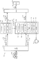
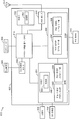
도 1 을 참조하면, 고-대역 재구성을 위한 위상 조정 파라미터들을 결정하도록 동작가능한 시스템의 특정 실시형태가 도시되고 개괄적으로 100 으로 지정된다. 특정 실시형태에서, 시스템 (100) 은 (예를 들어, 무선 전화기 또는 코더/디코더 (코덱)) 에서의) 인코딩 시스템 또는 장치에 통합될 수도 있다. 다른 실시형태들에서, 시스템 (100) 은 셋 탑 박스, 음악 재생기, 비디오 재생기, 엔터테인먼트 유닛, 네비게이션 디바이스, 통신 디바이스, PDA, 고정형 위치 데이터 유닛, 또는 컴퓨터에 통합될 수도 있다.Referring to FIG. 1, a particular embodiment of a system operable to determine phase adjustment parameters for high-band reconstruction is shown and generally designated 100. In certain embodiments, the
다음의 설명에서, 도 1 의 시스템 (100) 에 의해 수행되는 다양한 기능들은 소정의 컴포넌트들 또는 모듈들에 의해 수행되는 것으로 설명된다는 것에 유의해야 한다. 그러나, 이러한 컴포넌트들 및 모듈들의 분할은 단지 예시용이다. 대안적인 실시형태에서, 특정 컴포넌트 또는 모듈에 의해 수행되는 기능은 그 대신에 다수의 컴포넌트들 또는 모듈들 사이에서 분할될 수도 있다. 또한, 대안적인 실시형태에서, 도 1 의 2 개 이상의 컴포넌트들 또는 모듈들은 단일 컴포넌트 또는 모듈로 통합될 수도 있다. 도 1 에서 도시되는 각각의 컴포넌트 또는 모듈은 하드웨어 (예를 들어, 필드-프로그램가능 게이트 어레이 (field-programmable gate array; FPGA) 디바이스, 주문형 반도체 (application-specific integrated circuit; ASIC), 디지털 신호 프로세서 (digital signal processor; DSP), 제어기 등), 소프트웨어 (예를 들어, 프로세서에 의해 실행가능한 명령들), 또는 이의 임의의 조합을 이용하여 구현될 수도 있다.In the following description, it should be noted that the various functions performed by the
시스템 (100) 은 입력 오디오 신호 (102) 를 수신하도록 구성되는 분석 필터 뱅크 (110) 를 포함한다. 예를 들어, 입력 오디오 신호 (102) 는 마이크로폰 또는 다른 입력 디바이스에 의해 제공될 수도 있다. 특정 실시형태에서, 입력 오디오 신호 (102) 는 스피치 (speech) 를 포함할 수도 있다. 입력 오디오 신호 (102) 는 대략 50 Hz 에서 대략 16 kHz 까지의 주파수 범위에서 데이터를 포함하는 SWB 신호일 수도 있다. 분석 필터 뱅크 (110) 는 주파수에 기초하여 입력 오디오 신호 (102) 를 다수의 부분들로 필터링할 수도 있다. 예를 들어, 분석 필터 뱅크 (110) 는 저-대역 신호 (122) 및 고-대역 신호 (124) 를 생성할 수도 있다. 저-대역 신호 (122) 및 고-대역 신호 (124) 는 동일하거나 동일하지 않은 대역폭을 가질 수도 있고, 중첩하거나 중첩하지 않을 수도 있다. 대안적인 실시형태에서, 분석 필터 뱅크 (110) 는 2 개를 초과하는 출력들을 생성할 수도 있다.The
도 1 의 예에서, 저-대역 신호 (122) 및 고-대역 신호 (124) 는 중첩하지 않는 주파수 대역들을 차지한다. 예를 들어, 저-대역 신호 (122) 및 고-대역 신호 (124) 는 각각 50 Hz - 7 kHz 및 7 kHz - 16 kHz 의 중첩하지 않는 주파수 대역들을 차지할 수도 있다. 대안적인 실시형태들에서, 저-대역 신호 (122) 및 고-대역 신호 (124) 는 각각 50 Hz - 8 kHz 및 8 kHz - 16 kHz 의 중첩하지 않는 주파수 대역들을 차지할 수도 있다. 다른 대안적인 실시형태에서, 저-대역 신호 (122) 와 고-대역 신호 (124) 는 중첩하는데 (예를 들어, 각각 50 Hz - 8 kHz 및 7 kHz - 16 kHz), 이는 분석 필터 뱅크 (110) 의 저역-통과 필터 및 고역-통과 필터가 평활한 롤오프 (smooth rolloff) 를 갖는 것을 가능하게 할 수도 있으며, 이는 저역-통과 필터 및 고역-통과 필터의 설계를 간소화하고 비용을 감소시킬 수도 있다. 저-대역 신호 (122) 와 고-대역 신호 (124) 가 중첩하는 것은 또한 수신기에서 저-대역 신호와 고-대역 신호의 평활한 블렌딩을 가능하게 할 수도 있으며, 이는 보다 적은 가청 아티팩트들을 초래할 수도 있다.In the example of FIG. 1, the low-
비록 도 1 의 예가 SWB 신호의 프로세싱을 도시하나, 이는 단지 예시용이라는 것에 유의해야 한다. 대안적인 실시형태에서, 입력 오디오 신호 (102) 는 대략 50 Hz 내지 대략 8 kHz 의 주파수 범위를 갖는 WB 신호일 수도 있다. 그러한 실시형태에서, 저-대역 신호 (122) 는 대략 50 Hz 내지 대략 6.4 kHz 의 주파수 범위에 대응할 수도 있고, 고-대역 신호 (124) 는 대략 6.4 kHz 내지 대략 8 kHz 의 주파수 범위에 대응할 수도 있다.It should be noted that although the example of FIG. 1 shows the processing of the SWB signal, this is for illustrative purposes only. In an alternative embodiment, the
시스템 (100) 은 저-대역 신호 (122) 를 수신하도록 구성된 저-대역 분석 모듈 (130) 을 포함할 수도 있다. 특정 실시형태에서, 저-대역 분석 모듈 (130) 은 코드 여기 선형 예측 (code excited linear prediction; CELP) 인코더의 일 실시형태를 나타낼 수도 있다. 저-대역 분석 모듈 (130) 은 선형 예측 (linear prediction; LP) 분석 및 코딩 모듈 (132), 선형 예측 계수 (linear prediction coefficient; LPC) 대 LSP 모듈 (134), 및 양자화기 (136) 를 포함할 수도 있다. LSP 들은 또한 LSF 들이라고 지칭될 수도 있고, 2 개의 용어들 (LSP 및 LSF) 은 본원에서 상호교환가능하게 이용될 수도 있다. LP 분석 및 코딩 모듈 (132) 은 LPC 들의 세트로서 저-대역 신호 (122) 의 스펙트럼 포락선을 인코딩할 수도 있다. LPC 들은 오디오의 각각의 프레임 (예를 들어, 16 kHz 의 샘플링 레이트에서 320 개의 샘플들에 대응하는, 오디오의 20 밀리초 (ms)), 오디오의 각각의 서브-프레임 (예를 들어, 오디오의 5 ms), 또는 이의 임의의 조합에 대해 생성될 수도 있다. 각각의 프레임 또는 서브-프레임에 대해 생성되는 LPC 들의 개수는 수행되는 LP 분석의 "차수 (order)" 에 의해 결정될 수도 있다. 특정 실시형태에서, LP 분석 및 코딩 모듈 (132) 은 10-차 LP 분석에 대응하는 11 개의 LPC 들의 세트를 생성할 수도 있다.The
LPC 대 LSP 변환 모듈 (134) 은 (예를 들어, 일-대-일 변환을 이용하여) LP 분석 및 코딩 모듈 (132) 에 의해 생성되는 LPC 들의 세트를 대응하는 LSP 들의 세트로 변환할 수도 있다. 대안으로, LPC 들의 세트는 대응하는 파코 (parcor) 계수들, 로그-면적비 값들, 이미턴스 스펙트럼 쌍 (immittance spectral pair; ISP) 들, 또는 이미턴스 스펙트럼 주파수 (immittance spectral frequency; ISF) 들의 세트로 일-대-일 변환될 수도 있다. LPC 들의 세트와 LSP 들의 세트 사이의 변환은 에러 없이 거꾸로 할 수 있을 수도 있다.The LPC to
양자화기 (136) 는 변환 모듈 (134) 에 의해 생성되는 LSP 들의 세트를 양자화할 수도 있다. 예를 들어, 양자화기 (136) 는 다수의 엔트리들 (예를 들어, 벡터들) 을 포함하는 다수의 코드북들을 포함하거나 그에 연결될 수도 있다. LSP 들의 세트를 양자화하기 위해, 양자화기 (136) 는 LSP 들의 세트에 (예를 들어, 최소 제곱 또는 평균 제곱 에러와 같은 왜곡 측정에 기초하여) "가장 가까운" 코드북들의 엔트리들을 양자화할 수도 있다. 양자화기 (136) 는 코드북에서 식별된 엔트리들의 위치에 대응하는 인덱스 값 또는 인덱스 값들의 시리즈들을 출력할 수도 있다. 양자화기 (136) 의 출력은 따라서 저-대역 비트 스트림 (142) 에 포함되는 저-대역 필터 파라미터들을 나타낼 수도 있다.The
저-대역 분석 모듈 (130) 은 또한 저-대역 여기 신호 (144) 를 생성할 수도 있다. 예를 들어, 저-대역 여기 신호 (144) 는 저-대역 분석 모듈 (130) 에 의해 수행되는 LP 프로세스 중에 생성되는 LP 잔차 신호를 양자화함으로써 생성되는 인코딩된 신호일 수도 있다. LP 잔차 신호는 예측 에러를 나타낼 수도 있다.The low-
시스템 (100) 은 분석 필터 뱅크 (110) 로부터 고-대역 신호 (124) 를 그리고 저-대역 분석 모듈 (130) 로부터 저-대역 여기 신호 (144) 를 수신하도록 구성된 고-대역 분석 모듈 (150) 을 더 포함할 수도 있다. 고-대역 분석 모듈 (150) 은 고-대역 신호 (124) 및 저-대역 여기 신호 (144) 에 기초하여 고-대역 부가 정보 (172) 를 생성할 수도 있다. 예를 들어, 고-대역 부가 정보 (172) 는 고-대역 LSP 들, 이득 정보, 및/또는 위상 정보 (예를 들어, 위상 조정 파라미터들) 를 포함할 수도 있다. 특정 실시형태에서, 위상 정보는, 본원에서 더 설명되는 바와 같이, 제 1 신호 (180) 의 위상을 조정하는데 이용되는 고-대역 잔차 신호 (182) 에 기초한 위상 조정 파라미터들을 포함할 수도 있다.The
도시된 바와 같이, 고-대역 분석 모듈 (150) 은 LP 분석 및 코딩 모듈 (152), LPC 대 LSP 변환 모듈 (154), 및 양자화기 (156) 를 포함할 수도 있다. LP 분석 및 코딩 모듈 (152), 변환 모듈 (154), 및 양자화기 (156) 의 각각은 (예를 들어, 각각의 계수, LSP 등에 대해 보다 적은 비트들을 이용하여) 저-대역 분석 모듈 (130) 의 대응하는 컴포넌트들을 참조하여 위에서 설명된 바와 같이, 그러나 상대적으로 감소된 분해능으로 기능할 수도 있다. LP 분석 및 코딩 모듈 (152) 은 코드북 (163) 에 기초하여 변환 모듈 (154) 에 의해 LSP 들로 변환되고 양자화기 (156) 에 의해 양자화되는 LPC 들의 세트를 생성할 수도 있다. 예를 들어, LP 분석 및 코딩 모듈 (152), 변환 모듈 (154), 및 양자화기 (156) 는 고-대역 신호 (124) 를 이용하여 고-대역 부가 정보 (172) 에 포함된 고-대역 필터 정보 (예를 들어, 고-대역 LSP 들) 를 결정할 수도 있다. 고-대역 잔차 신호 (182) 는 LP 분석 및 코딩 모듈 (152) 의 잔차에 대응할 수도 있다. As shown, the high-
양자화기 (156) 는 변환 모듈 (154) 에 의해 제공되는 LSP 들과 같은 스펙트럼 주파수 값들의 세트를 양자화하도록 구성될 수도 있다. 다른 실시형태들에서, 양자화기 (156) 는 LSF 들 또는 LSP 들에 더해 또는 그것들 대신에, 하나 이상의 다른 유형의 스펙트럼 주파수 값들의 세트들을 수신하여 양자화할 수도 있다. 예를 들어, 양자화기 (156) 는 LP 분석 및 코딩 모듈 (152) 에 의해 생성되는 LPC 들의 세트를 수신하여 양자화할 수도 있다. 다른 예들은 양자화기 (156) 에서 수신되어 양자화될 수도 있는 파코 계수들, 로그-면적비 값들, 및 ISF 들의 세트들을 포함한다. 양자화기 (156) 는 코드북 (163) 과 같은 테이블 또는 코드북에서의 대응하는 엔트리에 대한 인덱스로서 입력 벡터 (예를 들어, 벡터 포맷인 스펙트럼 주파수 값들의 세트) 를 인코딩하는 벡터 양자화기를 포함할 수도 있다. 다른 예로서, 양자화기 (156) 는, 스토리지로부터 취출되기 보다는, 희소 (sparse) 코드북 구현에서와 같이, 입력 벡터가 디코더에서 다이내믹하게 생성될 수도 있는 하나 이상의 파라미터들을 결정하도록 구성될 수도 있다. 예시를 위해, 희소 코드북 예들은 3GPP2 (Third Generation Partnership 2) EVRC (Enhanced Variable Rate Codec) 와 같은 산업 표준들에 따른 CELP 및 코덱들과 같은 코딩 기법들에 적용될 수도 있다. 다른 실시형태에서, 고-대역 분석 모듈 (150) 은 양자화기 (156) 를 포함할 수도 있고, 다수의 코드북 벡터들을 이용하여 (예를 들어, 필터 파라미터들의 세트에 따라) 합성된 신호들을 생성하고, 예컨대 지각적으로 가중된 도메인에서, 고-대역 신호 (124) 에 가장 잘 매칭하는 합성된 신호와 연관된 코드북 벡터들 중 하나를 선택하도록 구성될 수도 있다.The
고-대역 분석 모듈 (150) 은 위상 분석기 (190) 를 포함할 수도 있다. 위상 분석기 (190) 는 고-대역 잔차 신호 (182) 들에 기초하여 위상 조정 파라미터들을 결정해 제 1 신호 (180) 의 위상을 조정하도록 구성될 수도 있다. 제 1 특정 실시형태에서, 위상 분석기 (190) 는 고-대역 잔차 신호 (182) 에 대해 변환 동작을 수행하여 고-대역 잔차 신호 (182) 를 시간-도메인에서 주파수-도메인으로 컨버팅하도록 구성될 수도 있다. 예를 들어, 위상 분석기 (190) 는 고-대역 잔차 신호 (182) 에 대해 FFT 동작을 수행할 수도 있다. The high-
고-대역 잔차 신호 (182) 에 대해 변환 동작을 수행하는 것은 고-대역 잔차 신호 (182) 의 대응하는 개수의 주파수들 (예를 들어, 128 개의 주파수들) 을 서술하는 다수의 변환 계수들 (예를 들어, 128 개의 푸리에 변환 계수들) 의 생성을 포함할 수도 있다. 각각의 변환 계수는 특정 주파수에서의 고-대역 잔차 신호 (182) 의 위상 정보 및 진폭 정보를 포함할 수도 있다. 위상 정보는 양자화되어 위상 조정 파라미터들을 생성할 수도 있다. 예를 들어, 양자화기 (미도시) 는 위상 정보를 위상 조정 파라미터들로 양자화할 수도 있다. 위상 조정 파라미터들은 고-대역 부가 정보 (172) 로서 (예를 들어, 고-대역 잔차 신호 (182) 의 위상을 보다 가깝게 모방하도록 제 1 신호 (180) 의 위상을 조정하기 위해) 위상 조정기 (192) 및 다중화기 (MUX) (170) 에 제공될 수도 있다.Performing a transform operation on the high-band
위상 분석기 (190) 는 각각의 주파수에 대한 위상 조정 파라미터를 생성하도록 구성될 수도 있거나, 위상 분석기 (190) 는 선택적 주파수들 (예를 들어, 고-대역 잔차 신호 (182) 의 스펙트럼 피크들과 연관된 주파수들) 에 대한 위상 조정 파라미터들을 생성하도록 구성될 수도 있다. 스펙트럼 피크들은 (예를 들어, 상대적으로 높은 및/또는 상대적으로 낮은) 에너지의 피크들을 넓어지게 하기 위해 고-대역 잔차 신호 (182) 를 분석함으로써 결정될 수도 있다. 예시적인 비제한적 예로서, 위상 분석기 (190) 는 고-대역 (예를 들어, 7 kHz - 16 kHz) 에서의 음성 프레임에 대한 기본 피치 주파수의 배수들에 대응하는 주파수들에 대한 위상 조정 파라미터들을 생성할 수도 있다. 예를 들어, 음성 프레임은 1.5 kHz 의 기본 피치 주파수를 가질 수도 있다. 위상 분석기 (190) 는 1.5 kHz 의 배수들 (예를 들어, 7.5 kHz, 9 kHz, 10.5 kHz 등) 에서 위상 조정 파라미터들을 생성할 수도 있다. 다른 예시적인 비제한적 예들로서, 위상 분석기 (190) 는 변환 계수들의 정규 간격들에 대응하는 주파수들에 대한 위상 조정 파라미터들을 생성할 수도 있다. 비제한적인 예로서, 위상 분석기 (190) 는 10 번째 변환 계수, 20 번째 변환 계수, 30 번째 변환 계수 등에 대응하는 주파수들에 대한 위상 조정 파라미터들을 생성할 수도 있다. 다른 특정 실시형태에서, 위상 분석기 (190) 는 5 번째 변환 계수, 10 번째 변환 계수, 15 번째 변환 계수 등에 대응하는 주파수들에 대한 위상 조정 파라미터들을 생성할 수도 있다. 간격들이 감소함에 따라 (예를 들어, 보다 많은 변환 계수들이 생성됨에 따라), 증가된 (그리고 보다 정확한) 고-대역 잔차 신호 (182) 의 위상 컴포넌트들이 캡쳐될 수도 있다.The
제 2 특정 실시형태에서, 위상 분석기 (190) 는 고-대역 잔차 신호 (182) 의 에너지 레벨들과 비슷한 사인곡선 파형들을 생성하도록 구성될 수도 있다. 예를 들어, 위상 분석기 (190) 는 고-대역 잔차 신호 (182) 의 스펙트럼 피크들에서 에너지 레벨들과 비슷한 "지배적인" 사인곡선 파형들을 반복하여 검색할 수도 있다. 에너지 레벨들의 근사치를 계산하는데 이용되는 사인곡선 파형들의 개수는 (예를 들어, 사인곡선 파형들과 고-대역 잔차 신호 (182) 사이의 평균 제곱 에러를 감소시키는) 에너지 레벨들과 비슷한 정확도와 증가된 개수의 사인곡선 파형들과 연관되는 증가된 비트 레이트 사이의 트레이드오프에 기초하여 결정될 수도 있다. 각각의 사인곡선 파형의 위상 컴포넌트, 진폭 컴포넌트, 및 주파수 컴포넌트는 양자화되어 고-대역 부가 정보 (174) 로서 위상 조정기 (192) 및 다중화기 (170) 에 제공될 수도 있다. 양자화된 위상 컴포넌트들은 위상 조정 파라미터들에 대응할 수도 있다.In a second particular embodiment, the
위상 조정기 (192) 는 위상 조정 파라미터들에 기초하여 제 1 신호 (180) 의 위상을 조정하도록 구성될 수도 있다. 위에서 설명된 제 1 실시형태에 따르면, 위상 조정기 (192) 는 제 1 신호 (180) 에 대해 변환 동작 (예를 들어, FFT 동작) 을 수행하여 제 1 신호 (180) 를 시간-도메인에서 주파수-도메인으로 컨버팅하도록 구성될 수도 있다. 위상 조정기 (192) 는 위상 분석기 (190) 에 의해 생성되는 위상 조정 파라미터들에 따라 (주파수-도메인에서) 제 1 신호 (180) 의 위상 컴포넌트들을 대체하거나 조정할 수도 있다. 예를 들어, 고-대역 잔차 신호 (182) 의 선택된 주파수들에 대한 위상 조정 파라미터들은 제 1 신호 (180) 의 대응하는 주파수들에 적용될 수도 있다. 제 1 신호 (180) 의 대응하는 주파수들에 위상 조정 파라미터들을 적용하는 것은 제 1 신호 (180) 의 위상 컴포넌트들을 고-대역 잔차 신호 (182) 로부터 추출되는 컴포넌트들로 대체할 수도 있다.The
위에서 설명되는 제 2 실시형태에 따르면, 위상 조정기 (192) 는 제 1 신호 (180) 의 에너지의 에너지 레벨들과 비슷한 사인곡선 파형들을 생성하도록 구성될 수도 있다. 위상 조정기 (192) 는 또한 제 1 신호 (180) 와 제 1 신호 (180) 의 에너지 레벨들과 비슷한 사인곡선 파형들 사이의 에너지 차이에 기초하여 잔차 사인곡선 파형을 생성하도록 구성될 수도 있다. 예를 들어, 잔차 파형은 제 1 신호 (180) 의 에너지 레벨들과 비슷한 사인곡선 파형들에 의해 캡쳐되지 않은 제 1 신호 (180) 의 잔류 에너지에 대응할 수도 있다. 위상 조정기 (192) 는 위상 분석기 (190) 에 의해 생성되는 위상 조정 파라미터들을 이용하여 위상 분석기 (190) 에 의해 생성되는 사인곡선 파형들을 재구성할 수도 있다. 잔차 사인곡선 파형은, 도 3 에 대해 설명되는 바와 같이, 고-대역 잔차 신호 (182) 의 위상에 기초하여 제 1 신호 (180) 의 위상을 조정하기 위해, 재구성된 사인곡선 파형들의 스케일링된 버전과 결합될 수도 있다.In accordance with the second embodiment described above, the
본원에서 설명되는 바와 같이, 제 1 신호 (180) 는 저-대역 신호 (122) 의 저-대역 여기의 고조파 확장된 버전 (예를 들어, 비선형적으로 확장된 버전) 일 수도 있다. 예를 들어, 저-대역 여기 신호 (144) 는 절대-값 연산 또는 제곱 연산을 겪어 저-대역 신호 (122) 의 저-대역 여기의 고조파 확장된 버전을 생성할 수도 있다. 대안으로, 제 1 신호 (180) 는 저-대역 신호 (122) 의 저-대역 여기의 고조파 확장된 버전으로부터 생성되는 고-대역 여기 신호일 수도 있다. 예를 들어, 백색 잡음이 저-대역 신호 (122) 의 저-대역 여기의 고조파 확장된 버전과 믹싱되어 고-대역 여기 신호를 생성할 수도 있다.As described herein, the
특정 실시형태에서, 고-대역 부가 정보 (172) 는 고-대역 LSP 들 뿐만 아니라 위상 조정 파라미터들을 포함할 수도 있다. 예를 들어, 고-대역 부가 정보 (172) 는 위상 분석기 (190) 에 의해 생성되는 위상 조정 파라미터들을 포함할 수도 있다.In certain embodiments, the high-
저-대역 비트 스트림 (142) 및 고-대역 부가 정보 (172) 는 다중화기 (170) 에 의해 다중화되어 출력 비트 스트림 (199) 을 생성할 수도 있다. 출력 비트 스트림 (199) 은 입력 오디오 신호 (102) 에 대응하는 인코딩된 오디오 신호를 나타낼 수도 있다. 예를 들어, 다중화기 (170) 는 고-대역 부가 정보 (172) 에 포함된 위상 조정 파라미터들을 입력 오디오 신호 (102) 의 인코딩된 버전에 삽입하여 입력 오디오 신호 (102) 의 재구성 중에 위상 조정을 가능하게 하도록 구성될 수도 있다. 출력 비트 스트림 (199) 은 송신기 (198) 에 의해 (예를 들어, 유선, 무선, 또는 광학 채널을 통해) 송신되고/되거나 저장될 수도 있다. 수신기에서, 수신 동작들은 역다중화기 (DEMUX), 저-대역 디코더, 고-대역 디코더, 및 필터 뱅크에 의해 수행되어 오디오 신호 (예를 들어, 스피커 또는 다른 출력 디바이스에 제공되는 입력 오디오 신호 (102) 의 재구성된 버전) 를 생성할 수도 있다. 저-대역 비트 스트림 (142) 을 나타내기 위해 이용되는 비트들의 수는 실질적으로 고-대역 부가 정보 (172) 를 나타내는데 이용되는 비트들의 수보다 클 수도 있다. 따라서, 출력 비트 스트림 (199) 에서의 비트들의 대부분은 저-대역 데이터를 나타낼 수도 있다. 고-대역 부가 정보 (172) 는 수신기에서 이용되어 신호 모델에 따라 저-대역 데이터로부터 고-대역 여기 신호를 재생성할 수도 있다. 예를 들어, 신호 모델은 저-대역 데이터 (예를 들어, 저-대역 신호 (122)) 와 고-대역 데이터 (예를 들어, 고-대역 신호 (124)) 사이의 예상되는 관계들 또는 상관들의 세트를 나타낼 수도 있다. 따라서, 상이한 종류의 오디오 데이터 (예를 들어, 스피치, 음악 등) 에 대해 상이한 신호 모델들이 이용될 수도 있고, 이용 중에 있는 특정 신호 모델은 인코딩된 오디오 데이터의 통신에 앞서 송신기 및 수신기에 의해 협의될 수도 있다 (또는 산업 표준에 의해 정의될 수도 있다). 신호 모델을 이용하여, 송신기에서의 고-대역 분석 모듈 (150) 은 수신기에서의 대응하는 고-대역 분석 모듈이 출력 비트 스트림 (199) 으로부터 고-대역 신호 (124) 를 재구성하기 위해 신호 모델을 이용하는 것이 가능하도록 고-대역 부가 정보 (172) 를 생성하는 것이 가능할 수도 있다.The low-
도 1 의 시스템 (100) 은 고-대역 잔차 신호 (182) 와 제 1 신호 (180) 사이의 위상 미스매치들을 감소시킬 수도 있다. 예를 들어, 시스템 (100) 은 고-대역 잔차 신호 (182) 와 고조파 확장된 신호 사이의, 또는 고-대역 잔차 신호(182) 와 고조파 확장된 신호로부터 생성되는 고-대역 여기 신호 사이의 위상 미스매치들을 감소시킬 수도 있다. 위상 미스매치들을 감소시키는 것은 입력 오디오 신호 (102) 의 고-대역 재구성 중에 이득 형상 추정을 향상시키고 가청 아티팩트들을 감소시킬 수도 있다. 예를 들어, 위상 미스매치들을 감소시키는 것은 제 1 신호 (180) (예를 들어, 고-대역 신호 (124) 의 합성된 버전을 생성하는데 이용되는 입력 오디오 신호 (102) 의 저-대역 부분들) 및 고-대역 잔차 신호 (182) 의 타이밍 정렬들을 향상시킬 수도 있다. 제 1 신호 (180) 와 고-대역 잔차 신호 (182) 를 정렬하는 것은 제 1 신호 (180) 와 고-대역 잔차 신호 (182) 사이의 보다 정확한 이득 형상 추정들을 가능하게 할 수도 있다. 위상 조정 파라미터들은 디코더에 송신되어 입력 오디오 신호 (102) 의 고-대역 재구성 중에 가청 아티팩트들을 감소시킬 수도 있다.The
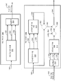
도 2 를 참조하면, 위상 분석기 (290) 및 위상 조정기 (202) 의 특정 실시형태들이 도시된다. 위상 분석기 (290) 는 도 1 의 위상 분석기 (190) 에 대응할 수도 있고, 위상 조정기 (292) 는 도 1 의 위상 조정기 (192) 에 대응할 수도 있다. 위상 분석기 (290) 는 위상 결정 모듈 (204) 을 포함하고, 위상 조정기 (292) 는 위상 조정 모듈 (210) 을 포함한다. 특정 실시형태에서, 위상 분석기 (290) 는 또한 제 1 변환 모듈 (202) 및 제 1 역 변환 모듈 (206) 을 포함할 수도 있다. 역 변환 모듈 (206) 은 도 2 의 위상 분석기 (290) 에 있는 것으로 도시되나, 대안적인 실시형태에서, 역 변환 모듈 (206) 은 위상 분석기 (290) 에서 부재할 수도 있다. 특정 실시형태에서, 위상 조정기 (292) 는 또한 제 2 변환 모듈 (208) 및 제 2 역 변환 모듈 (212) 을 포함할 수도 있다.Referring to FIG. 2, specific embodiments of phase analyzer 290 and
제 1 변환 모듈 (202) 은 도 1 의 고-대역 잔차 신호 (182) 를 시간-도메인에서 주파수-도메인 (예를 들어, 변환 도메인) 으로 컨버팅하도록 구성될 수도 있다. 예를 들어, 제 1 변환 모듈 (202) 은 고-대역 잔차 신호 (182) 에 대해 FFT 동작을 수행하여 고-대역 잔차 신호 (182) 를 주파수-도메인 고-대역 잔차 신호 (282) 로 컨버팅할 수도 있다.The
주파수-도메인 고-대역 잔차 신호 (282) 는 특정 주파수 대역들 (예를 들어, 주파수들) 내의 신호 특성들을 나타내는 변환 계수들에 의해 나타내어질 수도 있다. 각각의 변환 계수는 특정 주파수에 대한 위상 정보 및 특정 주파수에 대한 진폭 정보를 포함할 수도 있다. 예시적인 비제한적 예로서, 주파수-도메인 고-대역 잔차 신호 (282) 는 범위가 7 kHz 에서 16 kHz 사이인 주파수들을 포함할 수도 있고, 128 개의 FFT 계수들을 이용하여 나타내어질 수도 있다. 각각의 FFT 계수는 7 kHz 와 16 kHz 사이의 상이한 주파수들에서 고-대역 잔차 신호 (182) 와 연관되는 위상 정보를 포함할 수도 있다. 위상 정보는 위상 조정 파라미터들 (242) 로서 양자화기 (미도시) 에 의해 양자화되어 위상 조정기 (292) 에 제공될 수도 있다.Frequency-domain high-band
일부 구현들에서, 위상 결정 모듈 (204) 은 각각의 FFT 계수에 대응하는 주파수들에 대한 위상 조정 파라미터들을 결정하는 것에 반대로 선택적 FFT 계수들 (예를 들어, 특정 변환 계수들) 에 대응하는 주파수들에 대한 위상 조정 파라미터들 (242) 을 결정하도록 구성될 수도 있다. 예를 들어, 위상 결정 모듈 (204) 은 고-대역 (예를 들어, 7 kHz - 16 kHz) 에서의 음성 프레임에 대한 기본 피치 주파수의 정수 곱들에 대응하는 주파수들에 대한 위상 조정 파라미터들 (242) 을 결정할 수도 있다.In some implementations, the
다른 예로서, 위상 결정 모듈 (204) 은 특정 간격들에서 FFT 계수들에 대응하는 주파수들에 대한 위상 조정 파라미터들 (242) 을 결정할 수도 있다. 비제한적인 예로서, 위상 조정 파라미터들 (242) 은 매 10 번째 FFT 계수에 대응하는 주파수들의 제 1 간격에 대해 결정될 수도 있고, 위상 결정 모듈 (204) 은 고-대역 잔차 신호 (182) 의 스펙트럼 피크들의 특정 임계치 (예를 들어, 스펙트럼 피크들의 50%) 가 제 1 간격을 이용하여 캡쳐되는지 여부를 결정할 수도 있다. 특정 임계치가 만족되지 않는다는 결정에 응답하여, 위상 조정 파라미터들 (242) 은, 특정 임계치를 만족시키도록, 매 4 번째 FFT 계수 (예를 들어, 높은 해상도) 에 대응하는 것과 같은 주파수들의 제 2 간격에 대해 결정될 수도 있다. 따라서, 주파수들의 간격들은 스펙트럼 피크들의 특정 임계치를 캡쳐하는 위상 조정 파라미터들 (242) 을 생성하도록 조정될 수도 있다. 그 간격에 대응하는 데이터는 또한 양자화되어 위상 조정 파라미터들 (242) 과 함께 위상 조정기 (292) (및 다중화기 (170)) 로 송신될 수도 있다.As another example, the
제 1 역 변환 모듈 (206) 은 다시 시간-도메인으로 주파수-도메인 고-대역 잔차 신호 (282) 를 컨버팅하도록 구성될 수도 있다. 예를 들어, 제 1 역 변환 모듈 (206) 은 주파수-도메인 고-대역 잔차 신호 (282) 에 대해 역 고속 푸리에 변환 (Inverse Fast Fourier Transform; IFFT) 동작을 수행하여 주파수-도메인 고-대역 잔차 신호 (282) 를 다시 고-대역 잔차 신호 (182) (예를 들어, 시간-도메인 신호) 로 컨버팅할 수도 있다. 대안으로, (변환되지 않은) 고-대역 잔차 신호 (182) 가 추가적인 프로세싱을 위해 이용되도록 이용가능한 경우 위상 분석기 (290) 는 제 1 역 변환 모듈 (206) 을 포함하지 않을 수도 있다.The first
제 2 변환 모듈 (208) 은 제 1 변환 모듈 (202) 과 실질적으로 유사한 방식으로 동작할 수도 있다. 예를 들어, 제 2 변환 모듈 (208) 은 제 1 신호 (180) 를 시간-도메인에서 주파수-도메인으로 컨버팅하여 주파수-도메인 제 1 신호 (281) 를 생성하도록 구성될 수도 있다. 주파수-도메인 제 1 신호 (281) 는 위상 결정 모듈 (204) 로부터의 위상 조정 파라미터들 (242) 과 함께 위상 조정 모듈 (210) 에 제공될 수도 있다. 위상 조정 모듈 (210) 은 위상 조정 파라미터들 (242) 에 따라 주파수-도메인 제 1 신호 (281) 의 위상 컴포넌트들을 대체하도록 구성될 수도 있다. 예를 들어, 위상 조정 모듈 (210) 은 주파수-도메인 제 1 신호 (281) 의 위상들을 선택된 주파수들 (예를 들어, 선택된 간격들) 에서의 주파수-도메인 고-대역 잔차 신호의 위상들로 대체하여 조정된 주파수-도메인 제 1 신호 (283) 를 생성할 수도 있다. 주파수-도메인 제 1 신호 (281) 의 컴포넌트들의 위상들은 고-대역 잔차 신호 (182) 의 FFT 표현의 위상 컴포넌트들을 주파수-도메인 제 1 신호 (281) 의 위상 컴포넌트들 (예를 들어, 제 1 신호 (180) 의 FFT 표현) 로 대체함으로써 대체될 수도 있다.The
제 2 역 변환 모듈 (212) 은 제 1 역 변환 모듈 (206) 과 실질적으로 유사한 방식으로 동작할 수도 있다. 예를 들어, 제 2 역 변환 모듈 (212) 은 조정된 주파수-도메인 제 1 신호 (283) 를 주파수-도메인에서 시간-도메인으로 컨버팅하여 위상-조정된 신호 (244) 를 생성하도록 구성될 수도 있다.The second
각각 고-대역 잔차 신호 (182) 및 제 1 신호 (180) 를 시간-도메인에서 주파수-도메인으로 컨버팅하기 위해 변환 모듈들 (202, 208) 을 이용하는 것은 고-대역 잔차 신호 (182) 의 특정 주파수들에서의 위상 컴포넌트들 (예를 들어, 위상 조정 파라미터들 (242)) 이 결정되어 제 1 신호 (180) 에 적용되는 것을 가능하게 한다. 고-대역 잔차 신호 (182) 의 위상 컴포넌트들을 제 1 신호 (180) 에 적용하는 것은 고-대역 잔차 신호 (182) 와 제 1 신호 (180) 사이의 미스매치들을 오프셋할 수도 있으며, 이는 그렇지 않으면 가청 아티팩트들을 초래할 수도 있다.Using
다른 특정 실시형태에서, 위상 분석기 (290) 는 제 1 신호 (180) 와 고-대역 잔차 신호 (182) 사이의 위상 미스매치들을 결정할 수도 있다. 예를 들어, 제 1 변환 모듈 (202) 은 제 1 신호 (182) 에 대한 변환 계수들 및 고-대역 잔차 신호 (182) 에 대한 대응하는 변환 계수들을 결정할 수도 있다. 위상 결정 모듈 (204) 은 선택적 주파수 컴포넌트들 (예를 들어, 제 1 신호 (180) 및 고-대역 잔차 신호 (182) 에서의 피치 피크들) 에 대한 위상 미스매치의 정도를 결정할 수도 있다. 위상 미스매치의 정도는 위상 조정 파라미터들 (242) 로 양자화되고 위상 조정기 (292) 에 제공되어 위상 미스매치에 기초하여 제 1 신호 (180) 의 위상을 조정할 수도 있다.In another specific embodiment, the phase analyzer 290 may determine phase mismatches between the
특정 실시형태에서, 위상 조정기 (292) 는 다수의 주파수들에서 제 1 신호 (180) 의 위상을 조정할 수도 있다. 예를 들어, 위상 조정기 (292) 는 제 1 신호 (180) 의 제 1 변환 계수 및 고-대역 잔차 신호에 대응하는 제 1 주파수에서의 고-대역 잔차 신호 (182) 에서의 위상에 기초하여 제 1 신호 (180) 의 위상을 조정할 수도 있다. 위상 조정기 (292) 는 또한 제 1 신호 (180) 의 제 2 변환 계수 및 고-대역 잔차 신호 (182) 에 대응하는 제 2 주파수에서의 고-대역 잔차 신호 (182) 에서의 위상에 기초하여 제 1 신호 (180) 의 위상을 조정할 수도 있다.In certain embodiments, the
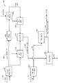
도 3 을 참조하면, 위상 분석기 (390) 및 위상 조정기 (392) 의 특정 실시형태들이 도시된다. 위상 분석기 (390) 는 도 1 의 위상 분석기 (190) 에 대응할 수도 있고, 위상 조정기 (392) 는 도 1 의 위상 조정기 (192) 에 대응할 수도 있다. 위상 분석기 (390) 는 제 1 사인곡선 분석 모듈 (302) 및 다중화기 (MUX) (304) 를 포함한다. 위상 조정기 (392) 는 제 2 사인곡선 분석 모듈 (308), 제 1 사인곡선 재구성 모듈 (310), 역다중화기 (DeMUX) (312), 및 제 2 사인곡선 재구성 모듈 (314) 을 포함한다.Referring to FIG. 3, specific embodiments of phase analyzer 390 and phase adjuster 392 are shown. The phase analyzer 390 may correspond to the
고-대역 잔차 신호 (182) 는 제 1 사인곡선 분석 모듈 (302) 에 제공될 수도 있다. 제 1 사인곡선 분석 모듈 (302) 은 고-대역 잔차 신호 (182) 의 특정 시간 인스턴스들에서의 (예를 들어, 시간-도메인 분석) 또는 특정 주파수들에서의 (예를 들어, 주파수-도메인 분석) 에너지 레벨들을 검출하도록 구성될 수도 있다. 검출된 에너지 레벨들에 기초하여, 제 1 사인곡선 분석 모듈 (302) 은 에너지 레벨들과 비슷한 사인곡선 파형들을 생성하도록 구성될 수도 있다. 예를 들어, 제 1 사인곡선 분석 모듈 (302) 은 검출된 에너지 레벨들의 특정 부분 (예를 들어, 스펙트럼 피크들) 을 캡쳐하기 위해 결합될 수 있는 사인곡선 파형들을 생성할 수도 있다. 본원에서 이용되는 바와 같이, "지배적인" 사인곡선 파형들은 근사치가 계산되고 있는 신호의 스펙트럼 피크들을 캡쳐하는 사인곡선 파형들에 대응할 수도 있다. 제 1 사인곡선 분석 모듈 (302) 은 지배적인 사인곡선들의 위상 정보 (322) 를 생성하도록 구성될 수도 있다. 특정 실시형태에서, 제 1 사인곡선 분석 모듈 (302) 은 또한 지배적인 사인곡선들의 진폭 정보 (324) 및 주파수 정보 (326) 를 생성할 수도 있다. 정보 (322-326) 는 위상 조정 파라미터들 (342) 로서 양자화기 (미도시) 에 의해 양자화되고 다중화기 (304) 에 의해 결합될 수도 있다.The high-band
제 1 신호 (180) 는 제 2 사인곡선 분석 모듈 (308) 및 제 1 믹서 (352) 에 제공될 수도 있다. 제 2 분석 모듈 (308) 은 제 1 사인곡선 분석 모듈 (302) 과 실질적으로 유사한 방식으로 동작할 수도 있다. 예를 들어, 제 2 사인곡선 분석 모듈 (308) 은 제 1 신호 (180) 의 에너지 레벨들과 비슷한 에너지 레벨들을 갖는 사인곡선들의 위상 정보 (332), 진폭 정보 (334), 및 주파수 정보 (336) 를 생성할 수도 있다. 정보 (322-336) 는 제 1 사인곡선 재구성 모듈 (310) 에 제공될 수도 있다.The
제 1 사인곡선 재구성 모듈 (310) 은 제 1 신호 (182) 를 사인곡선 파형들 (338) 로서 재구성하도록 구성될 수도 있다. 예를 들어, 사인곡선 파형들 (338) 은 정보 (322-336) 에 기초하여 제 1 신호 (180) 의 에너지 레벨들의 근사치를 계산할 수도 있다. 사인곡선 파형들 (338) 은 제 1 믹서 (352) 에 제공된다. 제 1 믹서 (352) 는 제 1 신호 (180) 로부터 사인곡선 파형들 (338) 의 컴포넌트들을 감산하여 사인곡선 파형들 (338) 과 제 1 신호 (180) 사이의 에너지 차이의 에너지 레벨들과 비슷한 잔차 파형 (340) 을 생성할 수도 있다.The first
위상 조정 파라미터들 (342) 은 역다중화기 (312) 에 제공될 수도 있다. 역다중화기 (312) 는 고-대역 잔차 신호 (182) 의 에너지 레벨의 에너지 레벨들과 비슷한 지배적인 사인곡선 파형들의 위상 정보 (322), 진폭 정보 (324), 및 주파수 정보 (326) 를 생성할 수도 있다. 정보 (322-336) 는 제 2 사인곡선 재구성 모듈 (314) 에 제공될 수도 있다. 제 2 사인곡선 재구성 모듈 (314) 은 제 1 사인곡선 재구성 모듈 (310) 과 실질적으로 유사한 방식으로 동작할 수도 있다. 예를 들어, 제 2 재구성 모듈 (314) 은 정보 (322-326) 에 기초하여 고-대역 잔차 신호 (182) 의 에너지 레벨들과 비슷한 사인곡선 파형들을 재구성하도록 구성될 수도 있고, 제 2 믹서 (354) (예를 들어, 스케일러/다중화기) 에 사인곡선 파형들을 제공할 수도 있다. 제 2 믹서 (354) 는 스케일 팩터에 기초하여 재구성된 사인곡선 파형들을 스케일링하여 스케일링된 재구성된 사인곡선 파형들을 생성할 수도 있다. 스케일 팩터는 통상적으로 제 1 신호 (180) 와 연관된 재구성된 사인곡선들 (즉, 저-대역 신호의 저-대역 여기의 고조파 확장된 버전 또는 고 대역 여기) 의 에너지들 및 고 대역 잔차 신호 (182) 와 연관된 재구성된 사인곡선들의 에너지들을 정규화하는데 이용된다. 잔차 파형 (340) 은 믹서 (356) 에서 스케일링된 재구성된 사인곡선 파형들과 믹싱되어 위상-조정된 제 1 신호 (344) 를 생성한다.
도 3 의 위상 분석기 (390) 및 위상 조정기 (392) 는 고-대역 잔차 신호 (182) 와 제 1 신호 (180) 사이의 미스매치들을 감소시킬 수도 있다. 위상 조정 파라미터들 (342) 은 고-대역을 서술하는 부가 정보에 포함될 수도 있다. 위상 미스매치들을 감소시키는 것은 입력 오디오 신호 (102) 의 고-대역 재구성 중에 이득 형상 추정을 향상시키고 가청 아티팩트들을 감소시킬 수도 있다. 예를 들어, 위상 미스매치들을 감소시키는 것은 제 1 신호 (180) (예를 들어, 고-대역 신호 (124) 의 합성된 버전을 생성하는데 이용되는 입력 오디오 신호 (102) 의 저-대역 부분들) 및 고-대역 잔차 신호 (182) 의 타이밍 정렬들을 향상시킬 수도 있다. 제 1 신호 (180) 와 고-대역 잔차 신호 (182) 를 정렬하는 것은 제 1 신호 (180) 와 고-대역 잔차 신호 (182) 사이의 보다 정확한 이득 형상 추정들을 가능하게 할 수도 있다.The phase analyzer 390 and phase adjuster 392 of FIG. 3 may reduce mismatches between the high-band
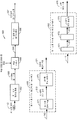
도 4 를 참조하면, 고-대역 재구성을 위한 위상 조정 파라미터들을 결정하도록 동작가능한 시스템 (400) 의 특정 실시형태가 도시된다. 시스템 (400) 은 선형 예측 분석 필터 (404), 비-선형 변환 생성기 (407), 위상 분석기 (490), 및 위상 조정기 (492) 를 포함한다.Referring to FIG. 4, a particular embodiment of a
저-대역 여기 신호 (144) 는 비-선형 변환 생성기 (407) 에 제공될 수도 있다. 도 1 에 대해 설명되는 바와 같이, 저-대역 여기 신호 (144) 는 저-대역 분석 모듈 (130) 을 이용하여 저-대역 신호 (122) (예를 들어, 입력 오디오 신호 (102) 의 저-대역 부분) 로부터 생성될 수도 있다. 비-선형 변환 생성기 (407) 는 저-대역 여기 신호 (144) 에 기초하여 고조파 확장된 신호 (480) 를 생성하도록 구성될 수도 있다. 예를 들어, 비-선형 변환 생성기 (407) 는 저-대역 여기 신호 (144) 의 프레임 (또는 서브-프레임들) 에 대해 절대-값 연산 또는 제곱 연산을 수행하여 고조파 확장된 신호 (480) 를 생성할 수도 있다.The low-
예시를 위해, 비-선형 변환 생성기 (407) 는 저-대역 여기 신호 (144) (예를 들어, 범위가 약 0 kHz 에서 8 kHz 까지인 8 kHz 신호) 를 업-샘플링하여 범위가 약 0 kHz 에서 16 kHz 까지인 16 kHz 신호 (예를 들어, 저-대역 여기 신호 (144) 의 약 2 배의 대역폭을 갖는 신호) 를 생성할 수도 있다. 16 kHz 신호의 저-대역 부분 (예를 들어, 약 0 kHz 내지 8 kHz) 은 저-대역 여기 신호 (144) 와 실질적으로 유사한 고조파를 가질 수도 있고, 16 kHz 신호의 고-대역 부분 (예를 들어, 약 8 kHz 내지 16 kHz) 은 실질적으로 고조파가 없을 수도 있다. 비-선형 변환 생성기 (407) 는 16 kHz 신호의 저-대역 부분에서 "지배적인" 고조파를 16 kHz 신호의 고-대역 부분으로 확장하여 고조파 확장된 신호 (480) 를 생성할 수도 있다. 따라서, 고조파 확장된 신호 (480) 는 비-선형 연산들 (예를 들어, 제곱 연산들 및/또는 절대 값 연산들) 을 이용하여 고-대역으로 확장하는 저-대역 여기 신호 (144) 의 고조파 확장된 버전일 수도 있다. 고조파 확장된 신호 (480) 는 위상 조정기 (492) 에 제공될 수도 있다. 고조파 확장된 신호 (480) 는 도 1 의 제 1 신호 (180) 에 대응할 수도 있다.For example, the
고-대역 신호 (124) 는 선형 예측 분석 필터 (404) 에 제공될 수도 있다. 선형 예측 분석 필터 (404) 는 고-대역 신호 (124) (예를 들어, 입력 오디오 신호 (102) 의 고-대역 부분) 에 기초하여 고-대역 잔차 신호 (482) 를 생성하도록 제공될 수도 있다. 예를 들어, 선형 예측 분석 필터 (404) 는 고-대역 신호 (124) 의 스펙트럼 포락선을 고-대역 신호 (124) 의 향후의 샘플들을 예측하는데 이용되는 LPC 들의 세트로서 인코딩할 수도 있다. 고-대역 잔차 신호 (482) 는 위상 분석기 (490) 에 제공될 수도 있다. 고-대역 잔차 신호 (482) 는 도 1 의 고-대역 잔차 신호 (182) 에 대응할 수도 있다.The high-
위상 분석기 (490) 는 도 1 의 위상 분석기 (190), 도 2 의 위상 분석기 (290), 또는 도 3 의 위상 분석기 (390) 에 대응할 수도 있고, 그것들과 실질적으로 유사한 방식으로 동작할 수도 있다. 예를 들어, 위상 분석기 (490) 는 고-대역 잔차 신호 (482) 에 기초하여 위상 조정 파라미터들 (442) 을 생성할 수도 있다. 위상 조정 파라미터들 (442) 은 도 2 의 위상 조정 파라미터들 (242) 또는 도 3 의 위상 조정 파라미터들 (342) 에 대응할 수도 있다. 위상 조정 파라미터들 (442) 은 고-대역 부가 정보 (172) 로서 도 1 의 위상 조정기 (492) 및 다중화기 (170) 에 제공될 수도 있다.The
위상 조정기 (492) 는 도 1 의 위상 조정기 (192), 도 2 의 위상 조정기 (292), 또는 도 3 의 위상 조정기 (392) 에 대응할 수도 있고, 그것들과 실질적으로 유사한 방식으로 동작할 수도 있다. 예를 들어, 위상 조정기 (492) 는 위상 조정 파라미터들 (442) 에 기초하여 고조파 확장된 신호 (480) 의 위상을 조정하여 조정된 고조파 확장된 신호 (444) 를 생성할 수도 있다. 조정된 고조파 확장된 신호 (444) 는 포락선 추적기 (402) 및 제 1 결합기 (454) 에 제공될 수도 있다.The
포락선 추적기 (402) 는 조정된 고조파 확장된 신호 (444) 를 수신하여 조정된 고조파 확장된 신호 (444) 에 대응하는 저-대역 시간-도메인 포락선 (403) 을 산출하도록 구성될 수도 있다. 예를 들어, 포락선 추적기 (402) 는 조정된 고조파 확장된 신호 (444) 의 프레임의 각각의 샘플의 제곱을 산출하여 제곱된 값들의 시퀀스를 생성하도록 구성될 수도 있다. 포락선 추적기 (402) 는, 예컨대, 제곱된 값들의 시퀀스에 1 차 무한 임펄스 응답 (infinite impulse response; IIR) 저-대역 필터를 적용함으로써, 제곱된 값들의 시퀀스에 대해 평활화 동작을 수행하도록 구성될 수도 있다. 포락선 추적기 (402) 는 평활화된 시퀀스의 각각의 샘플에 제곱근 함수를 적용하여 저-대역 시간-도메인 포락선 (403) 을 생성하도록 구성될 수도 있다. 저-대역 시간-도메인 포락선 (403) 은 잡음 결합기 (440) 에 제공될 수도 있다.The
잡음 결합기 (440) 는 저-대역 시간-도메인 포락선 (403) 을 백색 잡음 생성기 (미도시) 에 의해 생성되는 백색 잡음 (405) 과 결합하여 변조된 잡음 신호 (420) 를 생성하도록 구성될 수도 있다. 예를 들어, 잡음 결합기 (440) 는 저-대역 시간-도메인 포락선 (403) 에 따라 백색 잡음 (405) 을 진폭-변조하도록 구성될 수도 있다. 특정 실시형태에서, 잡음 결합기 (440) 는 저-대역 시간-도메인 포락선 (403) 에 따라 백색 잡음 (405) 을 스케일링하여 변조된 잡음 신호 (420) 를 생성하도록 구성되는 곱셈기로서 구현될 수도 있다. 변조된 잡음 신호 (420) 는 제 2 결합기 (456) 에 제공될 수도 있다.The
제 1 결합기 (454) 는 믹싱 팩터 (α) 에 따라 조정된 고조파 확장된 신호 (444) 를 스케일링하여 제 1 스케일링된 신호를 생성하도록 구성되는 곱셈기로서 구현될 수도 있다. 제 2 결합기 (456) 는 믹싱 팩터 (α) 에 따라 변조된 잡음 신호 (420) 를 스케일링하여 제 2 스케일링된 신호를 생성하도록 구성되는 곱셈기로서 구현될 수도 있다. 예를 들어, 제 2 결합기 (456) 는 1 마이너스 믹싱 팩터 (예를 들어, 1 - α) 의 차이에 기초하여 변조된 잡음 신호 (420) 를 스케일링할 수도 있다. 제 1 스케일링된 신호 및 제 2 스케일링된 신호는 믹서 (411) 에 제공될 수도 있다.The
믹서 (411) 는 믹싱 팩터 (α), 조정된 고조파 확장된 신호 (444), 및 변조된 잡음 신호 (420) 에 기초하여 고-대역 여기 신호 (461) 를 생성할 수도 있다. 예를 들어, 믹서 (411) 는 제 1 스케일링된 신호 및 제 2 스케일링된 신호를 믹싱하여 고-대역 여기 신호 (461) 를 생성할 수도 있다.The
도 4 의 시스템 (400) 은 위상 조정 파라미터들 (442) 에 기초하여 고조파 확장된 신호 (480) 의 위상을 조정하여 고-대역 재구성을 향상시킬 수도 있다. 고조파 확장된 신호 (480) 의 위상을 조정하는 것은 고-대역 잔차 신호 (482) 와 고조파 확장된 신호 (480) 사이의 위상 미스매치들을 감소시킬 수도 있다. 위상 미스매치들을 감소시키는 것은 고-대역 재구성 중에 이득 형상 추정을 향상시키고 가청 아티팩트들을 감소시킬 수도 있다. 예를 들어, 위상 미스매치들을 감소시키는 것은 고조파 확장된 신호 (480) 와 고-대역 잔차 신호 (482) 의 타이밍 정렬들을 향상시킬 수도 있다. 고조파 확장된 신호 (480) 와 고-대역 잔차 신호 (482) 를 정렬하는 것은 고조파 확장된 신호 (480) 와 고-대역 잔차 신호 (482) 사이의 보다 정확한 이득 형상 추정들을 가능하게 할 수도 있다.The
도 5 를 참조하면, 고-대역 재구성을 위한 위상 조정 파라미터들을 결정하도록 동작가능한 시스템 (500) 의 특정 예시적인 실시형태가 도시된다. 시스템 (500) 은 비-선형 변환 생성기 (407), 포락선 추적기 (402), 잡음 결합기 (440), 제 1 결합기 (454), 제 2 결합기 (456), 및 믹서 (411) 와 같은 도 4 에 대해 설명되는 컴포넌트들을 포함할 수도 있다. 도 4 에 대해 설명되는 컴포넌트들은, 조정된 고조파 확장된 신호 (444) 에 기초하여 고-대역 여기 신호 (461) 를 생성하는 대신에, 고조파 확장된 신호 (480) 에 기초하여 고-대역 여기 신호 (580) 를 생성할 수도 있다. 고-대역 여기 신호 (580) 는 도 1 의 제 1 신호 (180) 에 대응할 수도 있다.Referring now to FIG. 5, there is shown a particular exemplary embodiment of a
시스템 (500) 은 또한 도 4 의 선형 예측 분석 필터 (404) 를 포함할 수도 있다. 고-대역 신호 (124) 는 선형 예측 분석 필터 (404) 에 제공될 수도 있고, 선형 예측 분석 필터 (404) 는 고-대역 신호 (124) 에 기초하여 고-대역 잔차 신호 (482) 를 생성하도록 구성될 수도 있다. 고-대역 잔차 신호 (482) 는 도 1 의 고-대역 잔차 신호 (182) 에 대응할 수도 있다.The
시스템 (500) 은 또한 위상 분석기 (590) 를 포함할 수도 있다. 위상 분석기 (590) 는 도 1 의 위상 분석기 (190), 도 2 의 위상 분석기 (290), 또는 도 3 의 위상 분석기 (390) 에 대응할 수도 있고, 그것들과 실질적으로 유사한 방식으로 동작할 수도 있다. 예를 들어, 위상 분석기 (590) 는 고-대역 잔차 신호 (482) 에 기초하여 위상 조정 파라미터들 (542) 을 생성할 수도 있다. 위상 조정 파라미터들 (542) 은 도 2 의 위상 조정 파라미터들 (242) 또는 도 3 의 위상 조정 파라미터들 (342) 에 대응할 수도 있다. 위상 조정 파라미터들 (542) 은 고-대역 부가 정보 (172) 로서 도 1 의 위상 조정기 (592) 및 다중화기 (170) 에 제공될 수도 있다.The
위상 조정기 (592) 는 도 1 의 위상 조정기 (192), 도 2 의 위상 조정기 (292), 또는 도 3 의 위상 조정기 (392) 에 대응할 수도 있고, 그것들과 실질적으로 유사한 방식으로 동작할 수도 있다. 예를 들어, 위상 조정기 (592) 는 위상 조정 파라미터들 (542) 에 기초하여 고-대역 여기 신호 (580) 의 위상을 조정하여 조정된 고-대역 여기 신호 (544) 를 생성할 수도 있다.The
도 5 의 시스템 (500) 은 위상 조정 파라미터들 (542) 에 기초하여 고-대역 여기 신호 (580) 의 위상을 조정함으로써 고-대역 재구성을 향상시킬 수도 있다. 고-대역 여기 신호 (580) 의 위상을 조정하는 것은 고-대역 잔차 신호 (482) 와 고-대역 여기 신호 (580) 사이의 위상 미스매치들을 감소시킬 수도 있다. (도 4 의 고조파 확장된 신호 (480) 의 위상 대신에) 고-대역 여기 신호 (580) 의 위상을 조정하는 것은 도 4 의 백색 잡음 (405) 과 같은 잡음에 의해 야기되는 위상 저하를 감소시킬 수도 있다. 위상 미스매치들을 감소시키는 것은 고-대역 재구성 중에 이득 형상 추정을 향상시키고 가청 아티팩트들을 감소시킬 수도 있다.The
도 6 을 참조하면, 위상 조정 파라미터들을 이용하여 오디오 신호를 재구성하도록 동작가능한 시스템 (600) 의 특정 실시형태가 도시된다. 시스템 (600) 은 제 1 신호 재구성 회로부 (602) 및 위상 조정기 (692) 를 포함한다. 특정 실시형태에서, 시스템 (600) 은 (예를 들어, 무선 전화기 또는 코덱에서의) 디코딩 시스템 또는 장치에 통합될 수도 있다. 다른 특정 실시형태들에서, 시스템 (600) 은 셋 탑 박스, 음악 재생기, 비디오 재생기, 엔터테인먼트 유닛, 네비게이션 디바이스, 통신 디바이스, PDA, 고정형 위치 데이터 유닛, 또는 컴퓨터에 통합될 수도 있다.Referring to FIG. 6, a specific embodiment of a
제 1 신호 재구성 회로부 (602) 는 도 1 의 저-대역 비트 스트림 (142) 을 수신할 수도 있고, 저-대역 비트 스트림 (142) 에 기초하여 재구성된 제 1 신호 (680) (예를 들어, 도 1 내지 도 3 의 제 1 신호 (180) 의 재구성된 버전, 도 4 의 고조파 확장된 신호 (480) 의 재구성된 버전, 도 5 의 고-대역 여기 신호 (580) 의 재구성된 버전, 또는 이들의 임의의 조합) 를 생성하도록 구성될 수도 있다. 예를 들어, 제 1 신호 재구성 회로부 (602) 는 도 1 의 저-대역 분석 모듈 (130) 에 포함된 컴포넌트들과 유사한 컴포넌트들을 포함할 수도 있다. 또한, 제 1 신호 재구성 회로부 (602) 는 도 1 의 고-대역 분석 모듈 (150) 의 하나 이상의 컴포넌트들을 포함할 수도 있다. 재구성된 제 1 신호 (680) 는 위상 조정기 (692) 에 제공될 수도 있다.The first
제 1 신호 재구성 회로부 (602) 의 제 1 실시형태 (650) 는 저-대역 분석 모듈 (671) 및 비-선형 변환 생성기 (673) 를 포함할 수도 있다. 저-대역 분석 모듈 (671) 은 도 1 의 저-대역 분석 모듈 (130) 에 포함된 컴포넌트들과 유사한 컴포넌트들을 포함할 수도 있고 실질적으로 유사한 방식으로 동작할 수도 있다. 예를 들어, 저-대역 분석 모듈 (671) 은 저-대역 비트 스트림 (142) 에 기초하여 저-대역 여기 신호 (672) 를 생성할 수도 있다. 저-대역 여기 신호 (672) 는 비-선형 변환 생성기 (673) 에 제공될 수도 있다. 비-선형 변환 생성기 (673) 는 도 4 의 비-선형 변환 생성기 (407) 와 실질적으로 유사한 방식으로 동작할 수도 있다. 예를 들어, 비-선형 변환 생성기 (673) 는 고조파 확장된 신호 (674) (예를 들어, 제 1 신호 재구성 회로부 (602) 의 제 1 실시형태 (650) 에 따른 재구성된 제 1 신호 (680)) 를 생성할 수도 있다.The
제 1 신호 재구성 회로부 (602) 의 제 2 실시형태 (652) 는 저-대역 분석 모듈 (671), 비-선형 변환 생성기 (643), 및 고-대역 여기 생성기 (675) 를 포함할 수도 있다. 고조파 확장된 신호 (674) 는 고-대역 여기 생성기 (675) 에 제공될 수도 있다. 고-대역 여기 생성기 (675) 는 고조파 확장된 신호 (674) 에 기초하여 고-대역 여기 신호 (676) (예를 들어, 제 1 신호 재구성 회로부 (602) 의 제 2 실시형태 (652) 에 따른 재구성된 제 1 신호 (680)) 를 생성할 수도 있다.The
위상 조정 파라미터들 (642) 은 또한 위상 조정기 (692) 에 제공될 수도 있다. 위상 조정 파라미터들 (642) 은 도 2 내지 도 5 의 위상 조정 파라미터들 (242-542) 중 임의의 것에 대응할 수도 있다. 예를 들어, 도 1 의 고-대역 부가 정보 (172) 는 위상 조정 파라미터들 (642) 을 나타내는 데이터를 포함할 수도 있고, 위상 조정 파라미터들 (642) 을 나타내는 데이터는 시스템 (600) 에 송신될 수도 있다. 위상 조정기 (692) 는 위상 조정 파라미터들 (642) 에 기초하여 재구성된 제 1 신호 (680) 를 조정해 조정된 재구성된 제 1 신호 (644) 를 생성하도록 구성될 수도 있다. 특정 실시형태에서, 위상 조정기 (692) 는 도 1 내지 도 5 의 위상 조정기들 (192-592) 중 임의의 것과 실질적으로 유사한 방식으로 동작할 수도 있다. 조정된 재구성된 제 1 신호 (644) 는 고-대역 신호 재구성 회로부 (696) 에 재구성될 수도 있다. 고-대역 신호 재구성 회로부 (696) 는 시간/프레임 이득 조정, 합성 필터링, 또는 이들의 임의의 조합을 수행하여 재구성된 고-대역 신호 (624) 를 생성할 수도 있다. 재구성된 고-대역 신호 (624) 는 도 1 의 고-대역 신호 (124) 의 재구성된 버전일 수도 있다.
도 6 의 시스템 (600) 은 제 1 신호 (180) 및 위상 조정 파라미터들 (642) 을 이용하여 고-대역 신호 (124) 를 재구성할 수도 있다. 위상 조정 파라미터들 (642) 을 이용하는 것은 스피치 인코더에서 검출되는 고-대역 잔차 신호 (182) 의 에너지의 시간적 진화들에 기초하여 재구성된 제 1 신호 (680) 를 조정함으로써 재구성의 정확도를 향상시킬 수도 있다. 예를 들어, 조정된 재구성된 제 1 신호 (644) 의 위상은 고-대역 잔차 신호 (182) 의 위상의 근사치를 계산할 수도 있다. 고-대역 신호 재구성 회로부 (696) 는 조정된 재구성된 제 1 신호 (644) 및 고-대역 잔차 신호 (182) 의 위상들이 거의 동일한 경우 고-대역 부가 정보 (172) 를 통해 제공되는 고-대역과 연관되는 이득 형상 파라미터들 (미도시) 에 기초하여 조정된 재구성된 제 1 신호 (644) 의 이득을 보다 정확하게 조정할 수도 있다.The
도 7 을 참조하면, 고-대역 재구성을 위해 위상 조정 파라미터들을 이용하는 방법들 (700, 710) 의 특정 실시형태들의 플로차트들이 도시된다. 제 1 방법 (700) 은 도 1 의 시스템 (100), 도 1 내지 도 5 의 위상 분석기들 (190-590), 도 1 내지 도 5 의 위상 조정기들 (192-592), 및 도 4 내지 도 5 의 시스템들 (400-500) 에 의해 수행될 수도 있다. 제 2 방법 (710) 은 도 6 의 시스템 (600) 에 의해 수행될 수도 있다.Referring to FIG. 7, there are shown flowcharts of specific embodiments of
제 1 방법 (700) 은, 702 에서, 인코더에서, 고-대역 잔차 신호에 기초하여 위상 조정 파라미터들을 결정하는 단계를 포함한다. 예를 들어, 도 1 을 참조하면, 위상 분석기 (190) 는 고-대역 잔차 신호 (182) 들에 기초하여 위상 조정 파라미터들을 결정해 제 1 신호 (180) 의 위상을 조정할 수도 있다. 제 1 특정 실시형태에서, 위상 분석기 (190) 는 고-대역 잔차 신호 (182) 에 대해 변환 동작을 수행하여 고-대역 잔차 신호 (182) 를 시간-도메인에서 주파수-도메인으로 컨버팅하도록 구성될 수도 있다. 컨버팅된 고-대역 잔차 신호 (182) 의 변환 계수들은 각각의 주파수들에서 고-대역 잔차 신호 (182) 의 위상 정보 및 진폭 정보를 포함할 수도 있다. 위상 정보는 양자화되어 위상 조정 파라미터들을 생성할 수도 있고, 위상 조정 파라미터들은 (선택적 주파수들에서 고-대역 잔차 신호 (182) 의 위상을 모방하도록 제 1 신호 (180) 의 위상을 조정하기 위해) 위상 조정기 (192) 에 제공될 수도 있다.The
제 2 특정 실시형태에서, 위상 분석기 (190) 는 고-대역 잔차 신호 (182) 의 에너지 레벨들과 비슷한 사인곡선 파형들을 생성할 수도 있다. 예를 들어, 위상 분석기 (190) 는, 도 3 에 대해 설명된 바와 같이, 고-대역 잔차 신호 (182) 의 스펙트럼 피크들의 에너지 레벨들을 캡쳐하는 지배적인 사인곡선 파형들을 반복하여 검색할 수도 있다. 각각의 사인곡선 파형의 위상 컴포넌트, 진폭 컴포넌트, 및 주파수 컴포넌트는 양자화되어 고-대역 부가 정보 (174) 로서 위상 조정기 (192) 및 다중화기 (170) 에 제공될 수도 있다. 양자화된 위상 컴포넌트들은 위상 조정 파라미터들에 대응할 수도 있다.In a second particular embodiment, the
제 1 신호의 위상은, 704 에서, 위상 조정 파라미터들에 기초하여 조정될 수도 있다. 제 1 신호는 오디오 신호의 저-대역 부분과 연관될 수도 있다. 예를 들어, 도 1 을 참조하면, 위상 조정기 (192) 는 고-대역 잔차 신호 (182) 의 위상을 보다 근접하게 모방하도록 제 1 신호 (180) 의 위상을 조정할 수도 있다.The phase of the first signal may be adjusted at 704 based on the phase adjustment parameters. The first signal may be associated with a low-band portion of the audio signal. For example, referring to FIG. 1, the
위상 조정 파라미터들은, 706 에서, 오디오 신호의 인코딩된 버전에 삽입되어 오디오 신호의 인코딩된 버전으로부터 오디오 신호의 재구성 중에 위상 조정을 가능하게 할 수도 있다. 예를 들어, 도 1 의 고-대역 부가 정보 (172) 는 도 2 내지 도 5 의 위상 조정 파라미터들 (242-542) 중 하나 이상을 포함할 수도 있다. 다중화기 (170) 는 위상 조정 파라미터들을 비트 스트림 (199) 에 삽입할 수도 있다.The phase adjustment parameters may be inserted into the encoded version of the audio signal at 706 to enable phase adjustment during reconstruction of the audio signal from the encoded version of the audio signal. For example, the high-
위상 조정 파라미터들은, 708 에서, 비트스트림의 일부로서 스피치 디코더로 송신될 수도 있다. 예를 들어, 도 1 을 참조하면, (위상 조정 파라미터들을 포함하는) 비트 스트림 (199) 은 디코더 (예를 들어, 도 6 의 시스템 (600)) 로 송신될 수도 있다.The phase adjustment parameters may be transmitted to the speech decoder at 708 as part of the bitstream. For example, referring to FIG. 1, a bitstream 199 (including phase adjustment parameters) may be transmitted to a decoder (e.g.,
제 1 방법 (700) 은 저-대역 여기 신호와 함께 디코더에 제공되는 위상 조정 파라미터들을 생성할 수도 있다. 디코더는 위상 조정 파라미터들 및 저-대역 여기 신호에 기초하여 도 1 의 고-대역 신호 (124) 의 재구성된 버전을 생성할 수도 있다. 예를 들어, 디코더에 고-대역 신호 (124) 를 제공하는 것은 상대적으로 많은 양의 대역폭을 사용할 수도 있으나; 저-대역 여기 신호 및 위상 조정 파라미터들을 제공하는 것은 보다 적은 양의 대역폭을 사용할 수도 있다. 디코더는 위상 조정 파라미터들을 이용하여 고-대역 신호 (124) 의 위상을 모방하도록 저-대역 여기 신호로부터 생성되는 신호들 (예를 들어, 인코더에서 도 4 에 대해 설명된 바와 같은 고조파 확장된 신호 및/또는 인코더에서 도 5 에 대해 설명된 바와 같은 고-대역 여기 신호) 을 조정할 수도 있다. 고-대역 신호 (124) 의 위상을 모방하는 것은 디코더에서 타이밍 정렬들을 향상시킬 수도 있다. 향상된 타이밍 정렬들은 고-대역 신호 (124) 의 재구성된 버전을 생성하기 위해 디코더에서 보다 정확한 이득 조정들을 가능하게 할 수도 있다. 제 1 방법 (700) 은 인코더 기능들에 대한 것이나, 제 2 방법 (710) 은 디코더 기능들에 대한 것이다.The
제 2 방법 (710) 은, 712 에서, 디코더에서, 스피치 인코더로부터 인코딩된 오디오 신호를 수신하는 단계를 포함할 수도 있다. 인코딩된 오디오 신호는 스피치 인코더에서 생성되는 제 1 신호 (180) 의 위상을 조정하기 위해 스피치 인코더에서 생성되는 고-대역 잔차 신호 (182) 에 기초하여 위상 조정 파라미터들 (642) (예를 들어, 도 2 내지 도 5 의 위상 조정 파라미터들 (242-542) 중 하나 이상) 을 포함할 수도 있다.The
재구성된 제 1 신호는, 714 에서, 인코딩된 오디오 신호에 기초하여 생성될 수도 있다. 재구성된 제 1 신호는 오디오 신호의 저-대역 부분과 연관되는 인코더에서 생성된 제 1 신호의 재구성된 버전에 대응할 수도 있다. 예를 들어, 도 6 을 참조하면, 제 1 신호 재구성 회로부 (602) 는 인코더로부터의 저-대역 비트 스트림 (142) 에 기초하여 재구성된 제 1 신호 (680) 를 생성할 수도 있다.The reconstructed first signal may be generated at 714 based on the encoded audio signal. The reconstructed first signal may correspond to a reconstructed version of the first signal generated at the encoder associated with the low-band portion of the audio signal. For example, referring to FIG. 6, a first
위상 조정 파라미터들은, 716 에서, 재구성된 제 1 신호에 적용되어 재구성된 제 1 신호의 위상을 조정할 수도 있다. 예를 들어, 도 6 을 참조하면, 위상 조정기 (692) 는 재구성된 제 1 신호 (680) 에 위상 조정 파라미터들 (642) 을 적용하여 재구성된 제 1 신호 (680) 의 위상을 조정할 수도 있다.The phase adjustment parameters may be applied to the reconstructed first signal at 716 to adjust the phase of the reconstructed first signal. For example, referring to FIG. 6, the
오디오 신호는, 718 에서, 위상-조정된 재구성된 제 1 신호에 기초하여 재구성될 수도 있다. 예를 들어, 도 6 의 위상 조정기 (692) 는 위상 조정 파라미터들 (642) 에 기초하여 재구성된 제 1 신호 (680) 의 위상을 조정하여 위상-조정된 재구성된 제 1 신호 (644) 를 생성할 수도 있다. 위상-조정된 재구성된 제 1 신호 (644) 는 고-대역 신호 재구성 회로부 (696) 에 제공될 수도 있다. 고-대역 신호 재구성 회로부 (696) 는 시간/프레임 이득 조정, 합성 필터링, 또는 이들의 임의의 조합을 수행하여 재구성된 고-대역 신호 (624) 를 생성할 수도 있다. 재구성된 고-대역 신호 (624) 는 도 1 의 고-대역 신호 (124) 의 재구성된 버전일 수도 있다.The audio signal may be reconstructed at 718 based on the phase-adjusted reconstructed first signal. 6 adjusts the phase of the reconstructed
도 7 의 방법들 (700, 710) 은 고-대역 잔차 신호 (182) 와 고-대역 부가 정보 (172) 를 생성하는데 이용되는 제 1 신호 (180) 사이의 위상 미스매치들을 감소시킬 수도 있다. 예를 들어, 시스템 (100) 은 고-대역 잔차 신호 (182) 와 고조파 확장된 신호 사이의, 또는 고-대역 잔차 신호(182) 와 고조파 확장된 신호로부터 생성되는 고-대역 여기 신호 사이의 위상 미스매치들을 감소시킬 수도 있다. 위상 미스매치들을 감소시키는 것은 입력 오디오 신호 (102) 의 고-대역 재구성 중에 이득 형상 추정을 향상시키고 가청 아티팩트들을 감소시킬 수도 있다. 위상 조정 파라미터들은 디코더에 송신되어 입력 오디오 신호 (102) 의 고-대역 재구성 중에 가청 아티팩트들을 감소시킬 수도 있다.The
특정 실시형태들에서, 도 7 의 방법들 (700, 710) 은 중앙 프로세싱 유닛 (CPU), DSP, 또는 제어기와 같은 프로세싱 유닛의 하드웨어 (예를 들어, FPGA 디바이스, ASIC 등) 를 통해, 펌웨어 디바이스를 통해, 또는 이들의 임의의 조합으로 구현될 수도 있다. 일 예로서, 도 7 의 방법들 (700, 710) 은 도 8 에 대해 설명된 바와 같은 명령들을 실행하는 프로세서에 의해 수행될 수도 있다.In certain embodiments, the
도 8 을 참조하면, 무선 통신 디바이스의 특정 예시적인 실시형태의 블록도가 도시되고 전반적으로 800 으로 지정된다. 디바이스 (800) 는 메모리 (832) 에 연결된 프로세서 (810) (예를 들어, CPU) 를 포함한다. 메모리 (832) 는 도 7 의 방법들 (700, 710) 과 같은, 본원에 개시된 방법들 및 프로세스들을 수행하도록 프로세서 (810) 및/또는 코덱 (834) 에 의해 실행가능한 명령들 (860) 을 포함할 수도 있다.Referring now to FIG. 8, a block diagram of a specific exemplary embodiment of a wireless communication device is shown and generally designated 800. The
특정 실시형태에서, 코덱 (834) 은 위상-조정된 인코딩 시스템 (882) 및 위상-조정된 디코딩 시스템 (884) 을 포함할 수도 있다. 특정 실시형태에서, 위상-조정된 인코딩 시스템 (882) 은 도 1 의 시스템 (100) 의 하나 이상의 컴포넌트들, 도 2 의 위상 분석기 (290), 도 2 의 위상 조정기 (292), 도 3 의 위상 분석기 (390), 도 3 의 위상 조정기 (392), 및/또는 도 4 내지 도 5 의 시스템들 (400-500) 중 하나 이상의 컴포넌트들을 포함한다. 예를 들어, 위상-조정된 인코딩 시스템 (882) 은 도 1 의 시스템 (100), 도 2 의 위상 분석기 (290), 도 2 의 위상 조정기 (292), 도 3 의 위상 분석기 (390), 도 3 의 위상 조정기 (392), 도 4 내지 도 5 의 시스템들 (400-500), 및 도 7 의 방법 (700) 과 연관된 인코딩 동작들을 수행할 수도 있다. 특정 실시형태에서, 위상-조정된 디코딩 시스템 (884) 은 도 6 의 시스템 (600) 의 하나 이상의 컴포넌트들을 포함할 수도 있다. 예를 들어, 위상-조정된 디코딩 시스템 (884) 은 도 6 의 시스템 (600) 및 도 7 의 방법 (710) 과 연관된 디코딩 동작들을 수행할 수도 있다.In certain embodiments, the
위상-조정된 인코딩 시스템 (882) 및/또는 위상-조정된 디코딩 시스템 (884) 은 전용 하드웨어를 통해, 하나 이상의 태스크들을 수행하도록 명령들을 실행하는 프로세서에 의해, 또는 이들의 조합으로 구현될 수도 있다. 일 예로서, 코덱 (834) 에서의 메모리 (832) 또는 메모리 (890) 는 메모리 디바이스, 예컨대, 랜덤 액세스 메모리 (random access memory; RAM), 자기저항 랜덤 액세스 메모리 (magnetoresistive random access memory; MRAM), 스핀-토크 전송 MRAM (spin-torque transfer MRAM; STT-MRAM), 플래시 메모리, 판독 전용 메모리 (read only memory; ROM), 프로그램가능한 판독-전용 메모리 (programmable read-only memory; PROM), 소거가능한 프로그램가능 판독-전용 메모리 (erasable programmable read-only memory; EPROM), 전기적으로 소거가능한 프로그램가능 판독 전용 메모리 (electrically erasable programmable readonly memory; EEPROM), 레지스터들, 하드 디스크, 제거가능한 디스크, 또는 컴팩트 디스크 판독-전용 메모리 (compact disc read-only memory; CD-ROM) 일 수도 있다. 메모리 디바이스는, 컴퓨터 (예를 들어, 코덱 (834) 에서의 프로세서 및/또는 프로세서 (810)) 에 의해 실행되는 경우, 컴퓨터로 하여금, 도 7 의 방법들 (700, 710) 중 하나를 수행하게 하는 명령들 (예를 들어, 명령들 (860) 또는 명령들 (885)) 을 포함할 수도 있다. 일 예로서, 코덱 (834) 에서의 메모리 (832) 또는 메모리 (890) 는, 컴퓨터 (예를 들어, 코덱 (834) 에서의 프로세서 및/또는 프로세서 (810)) 에 의해 실행되는 경우, 컴퓨터로 하여금 도 7 의 방법들 (700, 710) 중 하나 이상을 수행하게 하는 명령들 (예를 들어, 각각 명령들 (860) 또는 명령들 (885)) 을 포함하는 비일시적 컴퓨터-판독가능 매체일 수도 있다.The phase-adjusted
디바이스 (800) 는 또한 코덱 (834) 및 프로세서 (810) 에 연결된 DSP (896) 를 포함할 수도 있다. 특정 실시형태에서, DSP (896) 는 위상-조정된 인코딩 시스템 (897) 및 위상-조정된 디코딩 시스템 (898) 을 포함할 수도 있다. 특정 실시형태에서, 위상-조정된 인코딩 시스템 (897) 은 도 1 의 시스템 (100) 의 하나 이상의 컴포넌트들, 도 2 의 위상 분석기 (290), 도 2 의 위상 조정기 (292), 도 3 의 위상 분석기 (390), 도 3 의 위상 조정기 (392), 및/또는 도 4 내지 도 5 의 시스템들 (400-500) 중 하나 이상의 컴포넌트들을 포함한다. 예를 들어, 위상-조정된 인코딩 시스템 (897) 은 도 1 의 시스템 (100), 도 2 의 위상 분석기 (290), 도 2 의 위상 조정기 (292), 도 3 의 위상 분석기 (390), 도 3 의 위상 조정기 (392), 도 4 내지 도 5 의 시스템들 (400-500), 및 도 7 의 방법 (700) 과 연관된 인코딩 동작들을 수행할 수도 있다. 특정 실시형태에서, 위상-조정된 디코딩 시스템 (898) 은 도 6 의 시스템 (600) 의 하나 이상의 컴포넌트들을 포함할 수도 있다. 예를 들어, 위상-조정된 디코딩 시스템 (898) 은 도 6 의 시스템 (600) 및 도 7 의 방법 (710) 과 연관된 디코딩 동작들을 수행할 수도 있다.The
도 8 은 또한 프로세서 (810) 및 디스플레이 (828) 에 연결되는 디스플레이 제어기 (826) 를 도시한다. 코덱 (834) 은, 도시된 바와 같이, 프로세서 (810) 에 연결될 수도 있다. 스피커 (836) 및 마이크로폰 (838) 이 코덱 (834) 에 연결될 수 있다. 예를 들어, 마이크로폰 (838) 은 도 1 의 입력 오디오 신호 (102) 를 생성할 수도 있고, 코덱 (834) 은 입력 오디오 신호 (102) 에 기초하여 수신기로의 송신을 위한 출력 비트 스트림 (199) 을 생성할 수도 있다. 다른 예로서, 스피커 (836) 는 도 1 의 출력 비트 스트림 (199) 으로부터 코덱 (834) 에 의해 재구성된 신호를 출력하는데 이용될 수도 있으며, 여기서 출력 비트 스트림 (199) 은 다른 디바이스로부터 수신된다. 도 8 은 또한 무선 제어기 (840) 가 디지털 신호 프로세서 (810) 및 안테나 (842) 에 연결될 수 있음을 나타낸다.8 also shows a
특정 실시형태에서, 프로세서 (810), 디스플레이 제어기 (826), 메모리 (832), 코덱 (834), 및 무선 제어기 (840) 는 시스템-인-패키지 또는 시스템-온-칩 디바이스 (예를 들어, 모바일 스테이션 모뎀 (mobile station modem; MSM)) (822) 에 포함된다. 특정 실시형태에서, 터치스크린 및/또는 키패드와 같은 입력 디바이스 (830) 및 및 전력 공급부 (844) 가 시스템-온-칩 디바이스 (822) 에 연결된다. 또한, 특정 실시형태에서는, 도 8 에 도시된 바와 같이, 디스플레이 (828), 입력 디바이스 (830), 스피커 (836), 마이크로폰 (838), 안테나 (842), 및 전력 공급부 (844) 는 시스템-온-칩 디바이스 (822) 의 외부에 있다. 그러나, 디스플레이 (828), 입력 디바이스 (830), 스피커 (836), 마이크 (838), 안테나 (842), 및 전원 공급기 (844) 의 각각은 인터페이스 또는 제어기와 같은 시스템-온-칩 디바이스 (822) 의 컴포넌트에 연결될 수 있다.In certain embodiments, the
설명된 실시형태들과 연계하여, 고-대역 잔차 신호에 기초하여 위상 조정 파라미터들을 결정하여 오디오 신호의 저-대역 부분과 연관된 제 1 신호의 위상을 조정하는 수단을 포함하는 제 1 장치가 개시된다. 예를 들어, 위상 조정 파라미터들을 결정하는 수단은 도 1 내지 도 5 의 위상 분석기들 (190-590), 도 8 의 위상-조정된 인코딩 시스템 (882), 도 8 의 코덱 (834), 도 8 의 위상-조정된 인코딩 시스템 (897), 위상 조정 파라미터들을 결정하도록 구성된 하나 이상의 디바이스들 (예를 들어, 비일시적 컴퓨터 판독가능 저장 매체에서 명령들을 실행하는 프로세서), 또는 이들의 임의의 조합 중 임의의 하나를 포함할 수도 있다.A first apparatus is disclosed that includes means for determining phase adjustment parameters based on a high-band residual signal and adjusting the phase of a first signal associated with a low-band portion of the audio signal in conjunction with the described embodiments . For example, the means for determining the phase adjustment parameters may include phase analyzers 190-590 in FIGS. 1-5, phase-adjusted
제 1 장치는 또한 위상 조정 파라미터들을 오디오 신호의 인코딩된 버전에 삽입하여 오디오 신호의 인코딩된 버전으로부터 오디오 신호의 재구성 중에 위상 조정을 가능하게 하는 수단을 포함할 수도 있다. 예를 들어, 위상 조정 파라미터들을 오디오 신호의 인코딩된 버전에 삽입하는 수단은 도 1 의 다중화기 (170), 도 8 의 위상-조정된 인코딩 시스템 (882), 도 8 의 코덱 (834), 도 8 의 위상-조정된 인코딩 시스템 (897), 위상 조정 파라미터들을 오디오 신호의 인코딩된 버전에 삽입하도록 구성된 하나 이상의 디바이스들 (예를 들어, 비일시적 컴퓨터 판독가능 저장 매체에서 명령들을 실행하는 프로세서), 또는 이들의 임의의 조합을 포함할 수도 있다.The first device may also include means for inserting phase adjustment parameters into the encoded version of the audio signal to enable phase adjustment during reconstruction of the audio signal from the encoded version of the audio signal. For example, the means for inserting the phase adjustment parameters into the encoded version of the audio signal may include the
설명된 실시형태들과 연계하여, 인코더로부터 인코딩된 오디오 신호를 수신하는 수단을 포함하는 제 2 장치가 개시되며, 여기서 인코딩된 오디오 신호는 인코더에 의해 생성된 고-대역 잔차 신호에 기초한 위상 조정 파라미터들을 포함한다. 위상 조정 파라미터들은 스피치 인코더에서 생성된 제 1 신호의 위상을 조정하기 위해 이용가능할 수도 있다. 예를 들어, 인코딩된 오디오 신호를 수신하는 수단은 도 6 의 제 1 신호 재구성 회로부 (602), 도 6 의 위상 조정기 (692), 도 8 의 위상-조정된 디코딩 시스템 (884), 수신기, 도 8 의 코덱 (834), 도 8 의 위상-조정된 디코딩 시스템 (898), 인코딩된 오디오 신호를 수신하도록 구성된 하나 이상의 디바이스들 (예를 들어, 비일시적 컴퓨터 판독가능 저장 매체에서의 명령들을 실행하는 프로세서), 또는 이들의 임의의 조합을 포함할 수도 있다.A second apparatus is disclosed that includes means for receiving an encoded audio signal from an encoder in conjunction with the described embodiments, wherein the encoded audio signal comprises a phase adjustment parameter based on a high-band residual signal generated by the encoder . The phase adjustment parameters may be available for adjusting the phase of the first signal generated in the speech encoder. For example, the means for receiving an encoded audio signal may include a first
제 2 장치는 또한 위상 조정 파라미터들에 기초하여 인코딩된 오디오 신호로부터 오디오 신호를 재구성하는 수단을 포함할 수도 있다. 예를 들어, 오디오 신호를 재구성하는 수단은 도 6 의 제 1 신호 재구성 회로부 (602), 도 6 의 위상 조정기 (692), 도 6 의 고-대역 신호 재구성 회로부 (696), 도 8 의 위상-조정된 디코딩 시스템 (884), 도 8 의 코덱 (834), 도 8 의 위상-조정된 디코딩 시스템 (898), 오디오 신호를 재구성하도록 구성된 하나 이상의 디바이스들 (예를 들어, 비일시적 컴퓨터 판독가능 저장 매체에서의 명령들을 실행하는 프로세서), 또는 이들의 임의의 조합을 포함할 수도 있다.The second device may also comprise means for reconstructing the audio signal from the encoded audio signal based on the phase adjustment parameters. For example, the means for reconstructing an audio signal may include the first
당업자라면, 본원에서 개시된 예시적인 실시형태들과 연계하여 설명된 다양한 예시적인 논리 블록들, 구성들, 모듈들, 회로들, 및 알고리즘 단계들이 전자 하드웨어, 프로세서에 의해 실행가능한 컴퓨터 소프트웨어, 또는 양자 모두의 조합으로서 구현될 수도 있음을 더 알 수 있을 것이다. 다양한 예시적인 컴포넌트들, 블록들, 구성들, 모듈들, 회로들, 및 단계들은 그 기능의 면에서 일반적으로 위에서 설명되었다. 그러한 기능성이 하드웨어 또는 소프트웨어로 구현되는지 여부는 특정 애플리케이션 및 전체 시스템에 부과되는 설계 제약들에 따라 달라진다. 당업자들은 각각의 특정 애플리케이션을 위해 다양한 방식들로 설명된 기능을 구현할 수도 있으나, 그러한 구현 결정들이 본 개시물의 범위로부터 벗어나게 하는 것으로 해석되어서는 안된다.Those of skill would further appreciate that the various illustrative logical blocks, configurations, modules, circuits, and algorithm steps described in connection with the exemplary embodiments disclosed herein may be implemented as electronic hardware, computer software executable by a processor, May be implemented as a combination of < / RTI > The various illustrative components, blocks, structures, modules, circuits, and steps have been described above generally in terms of their functionality. Whether such functionality is implemented in hardware or software depends upon the particular application and design constraints imposed on the overall system. Skilled artisans may implement the described functionality in varying ways for each particular application, but such implementation decisions should not be interpreted as causing a departure from the scope of the present disclosure.
본원에 개시된 실시형태들과 연계하여 설명된 방법 또는 알고리즘의 단계들은 하드웨어에서, 프로세서에 의해 실행되는 소프트웨어 모듈에서, 또는 이들 양자의 조합에서 직접적으로 구현될 수도 있다. 소프트웨어 모듈은 비일시적 저장 매체, 예컨대, 랜덤 액세스 메모리 (RAM), 자기저항 랜덤 액세스 메모리 (MRAM), 스핀-토크 전송 MRAM (STT-MRAM), 플래시 메모리, 판독 전용 메모리 (ROM), 프로그램가능 판독 전용 메모리 (PROM), 소거가능한 프로그램가능 판독 전용 메모리 (EPROM), 전기적으로 소거가능한 프로그램가능 판독-전용 메모리 (EEPROM), 레지스터들, 하드 디스크, 제거가능한 디스크, 또는 컴팩트 디스크 판독 전용 메모리 (CD-ROM) 에 있을 수도 있다. 일 예시적인 메모리 디바이스는 프로세서에 연결되어, 프로세서가 메모리 디바이스로부터 정보를 판독하고 메모리 디바이스에 정보를 기록할 수 있다. 대안에서, 메모리 디바이스는 프로세서에 통합될 수도 있다. 프로세서와 저장 매체는 ASIC 내에 있을 수도 있다. ASIC 는 컴퓨팅 디바이스 또는 사용자 단말기 내에 있을 수도 있다. 대안에서, 프로세서 및 저장 매체는 컴퓨팅 디바이스 또는 사용자 단말기에서 개별 컴포넌트들로서 있을 수도 있다.The steps of a method or algorithm described in connection with the embodiments disclosed herein may be embodied directly in hardware, in a software module executed by a processor, or in a combination of both. The software module may be a non-transitory storage medium such as random access memory (RAM), magnetoresistive random access memory (MRAM), spin-torque transfer MRAM (STT-MRAM), flash memory, read only memory A programmable read only memory (EPROM), an electrically erasable programmable read-only memory (EEPROM), registers, a hard disk, a removable disk, or a compact disk read-only memory (CD- ROM). One exemplary memory device is coupled to the processor such that the processor can read information from, and write information to, the memory device. In the alternative, the memory device may be integrated into the processor. The processor and the storage medium may reside in an ASIC. The ASIC may be in a computing device or user terminal. In the alternative, the processor and the storage medium may be separate components in a computing device or user terminal.
개시된 실시형태에 대한 앞서의 설명은 임의의 당업자가 개시된 실시형태들을 실시하거나 이용하는 것을 가능하게 하기 위해 제공된다. 이러한 실시형태들에 대한 다양한 수정예들이 당업자들에게는 자명할 것이고, 본원에서 정의된 일반적인 원칙들은 본 개시물의 범위를 벗어나지 않으면서 다른 실시형태들에 적용될 수도 있다. 따라서, 본 개시물은 본원에서 보여진 예시적인 실시형태들로 제한되도록 의도된 것이 아니고, 다음의 청구항들에 의해 정의된 원리들 및 신규한 특징들과 일치하는 가능한 가장 넓은 범위를 따르고자 한다.The previous description of the disclosed embodiments is provided to enable any person skilled in the art to make or use the embodiments disclosed. Various modifications to these embodiments will be readily apparent to those skilled in the art, and the generic principles defined herein may be applied to other embodiments without departing from the scope of the disclosure. Accordingly, the present disclosure is not intended to be limited to the exemplary embodiments shown herein but is to be accorded the widest possible scope consistent with the principles and novel features defined by the following claims.
Claims (30)
상기 위상 조정 파라미터들에 기초하여 제 1 신호의 위상을 조정하는 단계로서, 상기 제 1 신호는 오디오 신호의 저-대역 부분과 연관되는, 상기 제 1 신호의 위상을 조정하는 단계;
상기 오디오 신호의 상기 인코딩된 버전으로부터 상기 오디오 신호의 재구성 중에 위상 조정을 가능하게 하도록 상기 위상 조정 파라미터들을 상기 오디오 신호의 인코딩된 버전에 삽입하는 단계; 및
상기 위상 조정 파라미터들을 비트 스트림의 일부로서 스피치 디코더로 송신하는 단계
를 포함하는, 방법.In the encoder, determining phase adjustment parameters based on the high-band residual signal;
Adjusting a phase of the first signal based on the phase adjustment parameters, the first signal being associated with a low-band portion of the audio signal;
Inserting the phase adjustment parameters into an encoded version of the audio signal to enable phase adjustment during reconstruction of the audio signal from the encoded version of the audio signal; And
Transmitting the phase adjustment parameters as part of a bitstream to a speech decoder
/ RTI >
상기 제 1 신호는 고조파 확장된 신호에 기초하여, 또는 상기 고조파 확장된 신호로부터 생성되는 고-대역 여기 신호인, 방법.The method according to claim 1,
Wherein the first signal is a high-band excitation signal that is generated based on a harmonic extended signal, or from the harmonic extended signal.
상기 제 1 신호의 특정 위상 조정 파라미터를 결정하는 단계는 특정 주파수에서의 상기 고-대역 잔차 신호의 특정 위상을 결정하는 단계를 포함하고, 상기 특정 위상 조정 파라미터는 상기 특정 주파수에서의 상기 고-대역 잔차 신호의 상기 특정 위상과 연관된 양자화된 정보를 포함하는, 방법.The method according to claim 1,
Wherein determining the particular phase adjustment parameter of the first signal comprises determining a particular phase of the high-band residual signal at a particular frequency, wherein the specific phase adjustment parameter comprises a high- And quantized information associated with the particular phase of the residual signal.
상기 특정 주파수에서의 상기 고-대역 잔차 신호의 상기 특정 위상을 결정하는 단계는,
상기 고-대역 잔차 신호에 대해 변환 동작을 수행하여 상기 고-대역 잔차 신호를 시간 도메인으로부터 주파수 도메인으로 컨버팅하는 단계; 및
컨버팅된 상기 고-대역 잔차 신호의 특정 변환 계수를 선택하는 단계로서, 상기 특정 변환 계수는 상기 특정 주파수와 연관되고, 상기 특정 위상은 상기 특정 변환 계수에 기초하여 결정되는, 상기 컨버팅된 고-대역 잔차 신호의 특정 변환 계수를 선택하는 단계
를 포함하는, 방법.The method of claim 3,
Wherein determining the particular phase of the high-band residual signal at the particular frequency comprises:
Transforming the high-band residual signal from the time domain to the frequency domain by performing a transform operation on the high-band residual signal; And
Selecting a particular transform coefficient of the transformed high-band residual signal, wherein the specific transform coefficient is associated with the specific frequency, and wherein the specific phase is determined based on the specific transform coefficient. Selecting a specific transform coefficient of the residual signal
/ RTI >
상기 변환 동작은 고속 푸리에 변환 동작에 대응하는, 방법.5. The method of claim 4,
Wherein the transform operation corresponds to a fast Fourier transform operation.
상기 특정 주파수는 상기 오디오 신호의 고-대역 부분에서의 다수의 스피치 기본 피치 주파수에 대응하는, 방법.The method of claim 3,
Wherein the specific frequency corresponds to a plurality of speech fundamental pitch frequencies in a high-band portion of the audio signal.
상기 위상 조정 파라미터들은 규칙적인 주파수 간격들에서 결정되는, 방법.The method of claim 3,
Wherein the phase adjustment parameters are determined at regular frequency intervals.
상기 제 1 신호의 위상을 조정하는 단계는 상기 특정 위상 조정 파라미터에 기초하여 상기 특정 주파수에서의 상기 제 1 신호의 제 1 위상을 조정하는 단계를 포함하는, 방법.The method of claim 3,
Wherein adjusting the phase of the first signal comprises adjusting a first phase of the first signal at the particular frequency based on the particular phase adjustment parameter.
상기 특정 주파수에서의 상기 제 1 신호의 제 1 위상을 조정하는 단계는,
상기 제 1 신호에 대해 변환 동작을 수행하여 상기 제 1 신호를 시간 도메인으로부터 주파수 도메인으로 컨버팅하는 단계;
상기 제 1 신호가 상기 주파수 도메인에 있는 동안에 상기 특정 주파수에서의 상기 제 1 신호의 상기 제 1 위상을 상기 특정 주파수에서의 상기 고-대역 잔차 신호의 상기 특정 위상에 대응하는 조정된 위상으로 대체하여 위상-조정된 신호를 생성하는 단계; 및
상기 위상-조정된 신호에 대해 역 변환 동작을 수행하여 상기 위상-조정된 신호를 상기 주파수 도메인으로부터 상기 시간 도메인으로 컨버팅하는 단계
를 포함하는, 방법.9. The method of claim 8,
Wherein adjusting the first phase of the first signal at the particular frequency comprises:
Converting the first signal from the time domain to the frequency domain by performing a conversion operation on the first signal;
Replaces the first phase of the first signal at the particular frequency with the adjusted phase corresponding to the particular phase of the high-band residual signal at the particular frequency while the first signal is in the frequency domain Generating a phase-adjusted signal; And
Regenerating the phase-adjusted signal to convert the phase-adjusted signal from the frequency domain to the time domain;
/ RTI >
상기 고-대역 잔차 신호의 에너지 레벨과 비슷한 제 1 에너지 레벨을 갖는 적어도 제 1 사인곡선 파형을 생성하는 단계;
적어도 하나의 사인곡선 파형의 특정 위상을 결정하는 단계로서, 상기 위상 조정 파라미터들 중 특정 위상 조정 파라미터는 상기 제 1 사인곡선 파형의 특정 위상에 적어도 부분적으로 기초하는, 상기 적어도 하나의 사인곡선 파형의 특정 위상을 결정하는 단계;
상기 제 1 신호의 에너지 레벨과 비슷한 제 2 에너지 레벨을 갖는 적어도 제 2 사인곡선 파형을 생성하는 단계;
상기 제 2 사인곡선 파형과 상기 제 1 신호 사이의 에너지 차이와 비슷한 잔차 파형을 생성하는 단계;
상기 특정 위상 조정 파라미터에 기초하여 상기 제 1 사인곡선 파형을 재구성하여 재구성된 사인곡선 파형을 생성하는 단계; 및
상기 잔차 파형을 상기 재구성된 사인곡선 파형과 결합하여 위상-조정된 제 1 신호를 생성하는 단계
를 더 포함하는, 방법.The method according to claim 1,
Generating at least a first sinusoidal waveform having a first energy level that is similar to an energy level of the high-band residual signal;
Determining a particular phase of at least one sinusoidal waveform, wherein a particular one of the phase adjustment parameters is based at least in part on a particular phase of the first sinusoidal waveform; Determining a specific phase;
Generating at least a second sinusoidal waveform having a second energy level that is similar to the energy level of the first signal;
Generating a residual waveform that is similar to an energy difference between the second sinusoidal waveform and the first signal;
Reconstructing the first sinusoidal waveform based on the specific phase adjustment parameter to generate a reconstructed sinusoidal waveform; And
Combining the residual waveform with the reconstructed sinusoidal waveform to generate a phase-adjusted first signal
≪ / RTI >
상기 위상 조정 파라미터들에 기초하여 제 1 신호의 위상을 조정하도록 구성된 위상 조정기로서, 상기 제 1 신호는 오디오 신호의 저-대역 부분과 연관되는, 상기 위상 조정기; 및
상기 오디오 신호의 상기 인코딩된 버전으로부터 상기 오디오 신호의 재구성 중에 위상 조정을 가능하게 하기 위해 상기 위상 조정 파라미터들을 상기 오디오 신호의 인코딩된 버전에 삽입하도록 구성된 다중화기
를 포함하는, 장치.At the encoder, a phase analyzer configured to determine phase adjustment parameters based on the high-band residual signal;
A phase adjuster configured to adjust a phase of a first signal based on the phase adjustment parameters, the first signal being associated with a low-band portion of an audio signal; And
A multiplexer configured to insert the phase adjustment parameters into an encoded version of the audio signal to enable phase adjustment during reconstruction of the audio signal from the encoded version of the audio signal;
.
상기 위상 조정 파라미터들을 비트 스트림의 일부로서 스피치 디코더로 송신하도록 구성된 송신기를 더 포함하는, 장치.12. The method of claim 11,
And a transmitter configured to transmit the phase adjustment parameters to a speech decoder as part of a bitstream.
상기 제 1 신호는 고조파 확장된 신호, 또는 상기 고조파 확장된 신호로부터 생성되는 고-대역 여기 신호인, 장치.12. The method of claim 11,
Wherein the first signal is a harmonic extended signal, or a high-band excitation signal generated from the harmonic extended signal.
상기 위상 분석기는 특정 주파수에서의 상기 고-대역 잔차 신호의 특정 위상을 결정하도록 구성되고, 상기 특정 위상 조정 파라미터는 상기 특정 주파수에서의 상기 고-대역 잔차 신호의 상기 특정 위상과 연관된 양자화된 정보를 포함하는, 장치.12. The method of claim 11,
Wherein the phase analyzer is configured to determine a particular phase of the high-band residual signal at a particular frequency, the specific phase adjustment parameter comprising quantized information associated with the particular phase of the high-band residual signal at the particular frequency Comprising:
상기 특정 주파수에서의 상기 고-대역 잔차 신호의 상기 특정 위상을 결정하는 것은,
상기 고-대역 잔차 신호에 대해 변환 동작을 수행하여 상기 고-대역 잔차 신호를 시간 도메인으로부터 주파수 도메인으로 컨버팅하는 것; 및
컨버팅된 상기 고-대역 잔차 신호의 특정 변환 계수를 선택하는 것으로서, 상기 특정 변환 계수는 상기 특정 주파수와 연관되고, 상기 특정 위상은 상기 특정 변환 계수에 기초하여 결정되는, 상기 컨버팅된 고-대역 잔차 신호의 특정 변환 계수를 선택하는 것
을 포함하는, 장치.15. The method of claim 14,
Determining a particular phase of the high-band residual signal at the particular frequency,
Performing a transform operation on the high-band residual signal to convert the high-band residual signal from the time domain to the frequency domain; And
Selecting a particular transform coefficient of the transformed high-band residual signal, wherein the particular transform coefficient is associated with the particular frequency, and wherein the particular phase is determined based on the specific transform coefficient. Selecting a specific transform coefficient of the signal
/ RTI >
상기 변환 동작은 고속 푸리에 변환 동작에 대응하는, 장치.16. The method of claim 15,
Wherein the transform operation corresponds to a fast Fourier transform operation.
상기 특정 주파수는 상기 오디오 신호의 고-대역 부분에서의 다수의 스피치 기본 피치 주파수에 대응하는, 장치.15. The method of claim 14,
Wherein the particular frequency corresponds to a plurality of speech fundamental pitch frequencies in a high-band portion of the audio signal.
상기 위상 분석기는 규칙적인 주파수 간격들에서 위상 조정 파라미터들을 결정하도록 구성되고, 상기 특정 주파수는 상기 규칙적인 주파수 간격들 중 일 간격에 의해 정의된 주파수에 대응하는, 장치.15. The method of claim 14,
Wherein the phase analyzer is configured to determine phase adjustment parameters at regular frequency intervals, wherein the specific frequency corresponds to a frequency defined by a period of one of the regular frequency intervals.
상기 위상 조정기는 상기 특정 위상 조정 파라미터에 기초하여 상기 특정 주파수에서의 상기 제 1 신호의 제 1 위상을 조정하도록 구성되는, 장치.15. The method of claim 14,
And the phase adjuster is configured to adjust a first phase of the first signal at the particular frequency based on the particular phase adjustment parameter.
상기 위상 조정기는,
상기 제 1 신호에 대해 변환 동작을 수행하여 상기 제 1 신호를 시간 도메인으로부터 주파수 도메인으로 컨버팅하고;
상기 제 1 신호가 상기 주파수 도메인에 있는 동안에 상기 특정 주파수에서의 상기 제 1 신호의 상기 제 1 위상을 상기 특정 주파수에서의 상기 고-대역 잔차 신호의 상기 특정 위상으로 대체하여 위상-조정된 신호를 생성하고;
상기 위상-조정된 신호에 대해 역 변환 동작을 수행하여 상기 위상-조정된 신호를 상기 주파수 도메인으로부터 상기 시간 도메인으로 컨버팅하도록
더 구성되는, 장치.20. The method of claim 19,
The phase adjuster includes:
Converting the first signal from the time domain to the frequency domain by performing a conversion operation on the first signal;
Replaces the first phase of the first signal at the particular frequency with the particular phase of the high-band residual signal at the particular frequency while the first signal is in the frequency domain, Generate;
And performing an inverse transform operation on the phase-adjusted signal to convert the phase-adjusted signal from the frequency domain to the time domain
Lt; / RTI >
상기 위상 조정 파라미터들에 기초하여 제 1 신호의 위상을 조정하는 수단으로서, 상기 제 1 신호는 오디오 신호의 저-대역 부분과 연관되는, 상기 제 1 신호의 위상을 조정하는 수단;
상기 오디오 신호의 상기 인코딩된 버전으로부터 상기 오디오 신호의 재구성 중에 위상 조정을 가능하게 하도록 상기 위상 조정 파라미터들을 상기 오디오 신호의 인코딩된 버전에 삽입하는 수단; 및
상기 위상 조정 파라미터들을 비트 스트림의 일부로서 스피치 디코더로 송신하는 수단
을 포함하는, 장치.At the encoder, means for determining phase adjustment parameters based on the high-band residual signal;
Means for adjusting a phase of the first signal based on the phase adjustment parameters, the first signal being associated with a low-band portion of the audio signal;
Means for inserting the phase adjustment parameters into an encoded version of the audio signal to enable phase adjustment during reconstruction of the audio signal from the encoded version of the audio signal; And
Means for transmitting the phase adjustment parameters to a speech decoder as part of a bitstream
/ RTI >
상기 제 1 신호는 고조파 확장된 신호, 또는 상기 고조파 확장된 신호로부터 생성되는 고-대역 여기 신호인, 장치.22. The method of claim 21,
Wherein the first signal is a harmonic extended signal, or a high-band excitation signal generated from the harmonic extended signal.
상기 제 1 신호의 특정 위상 조정 파라미터를 결정하는 수단은 특정 주파수에서의 상기 고-대역 잔차 신호의 특정 위상을 결정하는 수단을 포함하고, 특정 위상 조정 파라미터는 상기 특정 주파수에서의 상기 고-대역 잔차 신호의 상기 특정 위상과 연관된 양자화된 정보를 포함하는, 장치.22. The method of claim 21,
Wherein the means for determining a specific phase adjustment parameter of the first signal comprises means for determining a particular phase of the high-band residual signal at a particular frequency, and wherein the specific phase adjustment parameter comprises a high- And quantized information associated with the particular phase of the signal.
상기 특정 주파수에서의 상기 고-대역 잔차 신호의 특정 위상을 결정하는 수단은,
상기 고-대역 잔차 신호에 대해 변환 동작을 수행하여 상기 고-대역 잔차 신호를 시간 도메인으로부터 주파수 도메인으로 컨버팅하는 수단; 및
컨버팅된 상기 고-대역 잔차 신호의 특정 변환 계수를 선택하는 수단으로서, 상기 특정 변환 계수는 상기 특정 주파수와 연관되고, 상기 특정 위상은 상기 특정 변환 계수에 기초하여 결정되는, 상기 컨버팅된 고-대역 잔차 신호의 특정 변환 계수를 선택하는 수단
을 포함하는, 장치.24. The method of claim 23,
Wherein the means for determining a particular phase of the high-band residual signal at the particular frequency comprises:
Means for transforming the high-band residual signal from the time domain to the frequency domain by performing a transform operation on the high-band residual signal; And
Means for selecting a particular transform coefficient of the transformed high-band residual signal, wherein the particular transform coefficient is associated with the particular frequency, and wherein the particular phase is determined based on the specific transform coefficient; Means for selecting a specific transform coefficient of the residual signal
/ RTI >
상기 변환 동작은 고속 푸리에 변환 동작에 대응하는, 장치.25. The method of claim 24,
Wherein the transform operation corresponds to a fast Fourier transform operation.
상기 특정 주파수는 상기 오디오 신호의 고-대역 부분에서의 다수의 스피치 기본 피치 주파수에 대응하는, 장치.24. The method of claim 23,
Wherein the particular frequency corresponds to a plurality of speech fundamental pitch frequencies in a high-band portion of the audio signal.
상기 위상 조정 파라미터들은 규칙적인 주파수 간격들에서 결정되는, 장치.24. The method of claim 23,
Wherein the phase adjustment parameters are determined at regular frequency intervals.
디코더를 포함하고,
상기 디코더는,
인코더로부터 인코딩된 오디오 신호를 수신하는 것으로서, 상기 인코딩된 오디오 신호는 상기 인코더에 의해 생성된 고-대역 잔차 신호에 기초하여 위상 조정 파라미터들을 포함하는, 상기 인코더로부터 인코딩된 오디오 신호를 수신하고;
상기 인코딩된 오디오 신호에 기초하여 재구성된 제 1 신호를 생성하는 것으로서, 상기 재구성된 제 1 신호는 오디오 신호의 저-대역 부분과 연관되는 상기 인코더에서 생성된 제 1 신호의 재구성된 버전에 대응하는, 상기 인코딩된 오디오 신호에 기초하여 재구성된 제 1 신호를 생성하고;
상기 위상 조정 파라미터들을 상기 재구성된 제 1 신호에 적용하여 상기 재구성된 제 1 신호의 위상을 조정하고;
상기 위상-조정된 재구성된 제 1 신호에 기초하여 상기 오디오 신호를 재구성하도록
구성되는, 장치.As an apparatus,
Decoder,
The decoder includes:
Receiving an encoded audio signal from the encoder, the encoded audio signal comprising phase adjustment parameters based on a high-band residual signal generated by the encoder;
Generating a reconstructed first signal based on the encoded audio signal, wherein the reconstructed first signal corresponds to a reconstructed version of the first signal generated by the encoder associated with a low-band portion of the audio signal Generating a reconstructed first signal based on the encoded audio signal;
Adjusting the phase of the reconstructed first signal by applying the phase adjustment parameters to the reconstructed first signal;
And to reconstruct the audio signal based on the phase-adjusted reconstructed first signal
Lt; / RTI >
상기 재구성된 제 1 신호는 고조파 확장된 신호인, 장치.29. The method of claim 28,
Wherein the reconstructed first signal is a harmonic extended signal.
상기 재구성된 제 1 신호는 고조파 확장된 신호로부터 생성되는 고-대역 여기 신호인, 장치.29. The method of claim 28,
Wherein the reconstructed first signal is a high-band excitation signal generated from a harmonic extended signal.
Applications Claiming Priority (5)
| Application Number | Priority Date | Filing Date | Title |
|---|---|---|---|
| US201361907674P | 2013-11-22 | 2013-11-22 | |
| US61/907,674 | 2013-11-22 | ||
| US14/550,589 US9858941B2 (en) | 2013-11-22 | 2014-11-21 | Selective phase compensation in high band coding of an audio signal |
| PCT/US2014/066945 WO2015077641A1 (en) | 2013-11-22 | 2014-11-21 | Selective phase compensation in high band coding |
| US14/550,589 | 2014-11-21 |
Publications (1)
| Publication Number | Publication Date |
|---|---|
| KR20160087827A true KR20160087827A (en) | 2016-07-22 |
Family
ID=52114054
Family Applications (1)
| Application Number | Title | Priority Date | Filing Date |
|---|---|---|---|
| KR1020167015203A KR20160087827A (en) | 2013-11-22 | 2014-11-21 | Selective phase compensation in high band coding |
Country Status (5)
| Country | Link |
|---|---|
| US (1) | US9858941B2 (en) |
| JP (1) | JP6345780B2 (en) |
| KR (1) | KR20160087827A (en) |
| CN (1) | CN105765655A (en) |
| WO (1) | WO2015077641A1 (en) |
Cited By (1)
| Publication number | Priority date | Publication date | Assignee | Title |
|---|---|---|---|---|
| KR20190067825A (en) * | 2016-10-31 | 2019-06-17 | 퀄컴 인코포레이티드 | Decoding of a plurality of audio signals |
Families Citing this family (11)
| Publication number | Priority date | Publication date | Assignee | Title |
|---|---|---|---|---|
| FR3011408A1 (en) * | 2013-09-30 | 2015-04-03 | Orange | RE-SAMPLING AN AUDIO SIGNAL FOR LOW DELAY CODING / DECODING |
| WO2015077641A1 (en) * | 2013-11-22 | 2015-05-28 | Qualcomm Incorporated | Selective phase compensation in high band coding |
| EP2963648A1 (en) | 2014-07-01 | 2016-01-06 | Fraunhofer-Gesellschaft zur Förderung der angewandten Forschung e.V. | Audio processor and method for processing an audio signal using vertical phase correction |
| US10460736B2 (en) * | 2014-11-07 | 2019-10-29 | Samsung Electronics Co., Ltd. | Method and apparatus for restoring audio signal |
| US10847170B2 (en) | 2015-06-18 | 2020-11-24 | Qualcomm Incorporated | Device and method for generating a high-band signal from non-linearly processed sub-ranges |
| US10152977B2 (en) * | 2015-11-20 | 2018-12-11 | Qualcomm Incorporated | Encoding of multiple audio signals |
| JP6611042B2 (en) * | 2015-12-02 | 2019-11-27 | パナソニックIpマネジメント株式会社 | Audio signal decoding apparatus and audio signal decoding method |
| US10148416B2 (en) * | 2016-09-02 | 2018-12-04 | Intel Corporation | Signal phase optimization in memory interface training |
| US10825467B2 (en) * | 2017-04-21 | 2020-11-03 | Qualcomm Incorporated | Non-harmonic speech detection and bandwidth extension in a multi-source environment |
| US10847172B2 (en) * | 2018-12-17 | 2020-11-24 | Microsoft Technology Licensing, Llc | Phase quantization in a speech encoder |
| US10957331B2 (en) * | 2018-12-17 | 2021-03-23 | Microsoft Technology Licensing, Llc | Phase reconstruction in a speech decoder |
Family Cites Families (29)
| Publication number | Priority date | Publication date | Assignee | Title |
|---|---|---|---|---|
| US4433434A (en) * | 1981-12-28 | 1984-02-21 | Mozer Forrest Shrago | Method and apparatus for time domain compression and synthesis of audible signals |
| WO1998005029A1 (en) | 1996-07-30 | 1998-02-05 | British Telecommunications Public Limited Company | Speech coding |
| US5886276A (en) * | 1997-01-16 | 1999-03-23 | The Board Of Trustees Of The Leland Stanford Junior University | System and method for multiresolution scalable audio signal encoding |
| SE512719C2 (en) * | 1997-06-10 | 2000-05-02 | Lars Gustaf Liljeryd | A method and apparatus for reducing data flow based on harmonic bandwidth expansion |
| US6266644B1 (en) * | 1998-09-26 | 2001-07-24 | Liquid Audio, Inc. | Audio encoding apparatus and methods |
| WO2003007480A1 (en) * | 2001-07-13 | 2003-01-23 | Matsushita Electric Industrial Co., Ltd. | Audio signal decoding device and audio signal encoding device |
| EP1423847B1 (en) * | 2001-11-29 | 2005-02-02 | Coding Technologies AB | Reconstruction of high frequency components |
| US20030187663A1 (en) * | 2002-03-28 | 2003-10-02 | Truman Michael Mead | Broadband frequency translation for high frequency regeneration |
| JP2004054526A (en) * | 2002-07-18 | 2004-02-19 | Canon Finetech Inc | Image processing system, printer, control method, method of executing control command, program and recording medium |
| ATE425533T1 (en) * | 2003-07-18 | 2009-03-15 | Koninkl Philips Electronics Nv | LOW BIT RATE AUDIO ENCODING |
| KR100707174B1 (en) | 2004-12-31 | 2007-04-13 | 삼성전자주식회사 | High band Speech coding and decoding apparatus in the wide-band speech coding/decoding system, and method thereof |
| US8078474B2 (en) | 2005-04-01 | 2011-12-13 | Qualcomm Incorporated | Systems, methods, and apparatus for highband time warping |
| KR101171098B1 (en) * | 2005-07-22 | 2012-08-20 | 삼성전자주식회사 | Scalable speech coding/decoding methods and apparatus using mixed structure |
| US7953605B2 (en) * | 2005-10-07 | 2011-05-31 | Deepen Sinha | Method and apparatus for audio encoding and decoding using wideband psychoacoustic modeling and bandwidth extension |
| US7546237B2 (en) * | 2005-12-23 | 2009-06-09 | Qnx Software Systems (Wavemakers), Inc. | Bandwidth extension of narrowband speech |
| ATE442645T1 (en) * | 2006-02-06 | 2009-09-15 | France Telecom | METHOD AND DEVICE FOR HIERARCHICAL CODING OF A SOURCE TONE SIGNAL AND CORRESPONDING DECODING METHOD AND DEVICE, PROGRAMS AND SIGNAL |
| CN101089951B (en) * | 2006-06-16 | 2011-08-31 | 北京天籁传音数字技术有限公司 | Band spreading coding method and device and decode method and device |
| KR101565919B1 (en) * | 2006-11-17 | 2015-11-05 | 삼성전자주식회사 | Method and apparatus for encoding and decoding high frequency signal |
| KR101411900B1 (en) * | 2007-05-08 | 2014-06-26 | 삼성전자주식회사 | Method and apparatus for encoding and decoding audio signal |
| EP2144229A1 (en) | 2008-07-11 | 2010-01-13 | Fraunhofer-Gesellschaft zur Förderung der angewandten Forschung e.V. | Efficient use of phase information in audio encoding and decoding |
| JP4932917B2 (en) * | 2009-04-03 | 2012-05-16 | 株式会社エヌ・ティ・ティ・ドコモ | Speech decoding apparatus, speech decoding method, and speech decoding program |
| US8484020B2 (en) * | 2009-10-23 | 2013-07-09 | Qualcomm Incorporated | Determining an upperband signal from a narrowband signal |
| US8326607B2 (en) * | 2010-01-11 | 2012-12-04 | Sony Ericsson Mobile Communications Ab | Method and arrangement for enhancing speech quality |
| RU2596033C2 (en) * | 2010-03-09 | 2016-08-27 | Фраунхофер-Гезелльшафт цур Фёрдерунг дер ангевандтен Форшунг Е.Ф. | Device and method of producing improved frequency characteristics and temporary phasing by bandwidth expansion using audio signals in phase vocoder |
| JP5743137B2 (en) * | 2011-01-14 | 2015-07-01 | ソニー株式会社 | Signal processing apparatus and method, and program |
| EP2631906A1 (en) * | 2012-02-27 | 2013-08-28 | Fraunhofer-Gesellschaft zur Förderung der angewandten Forschung e.V. | Phase coherence control for harmonic signals in perceptual audio codecs |
| WO2015077641A1 (en) * | 2013-11-22 | 2015-05-28 | Qualcomm Incorporated | Selective phase compensation in high band coding |
| US9564141B2 (en) * | 2014-02-13 | 2017-02-07 | Qualcomm Incorporated | Harmonic bandwidth extension of audio signals |
| US9542955B2 (en) * | 2014-03-31 | 2017-01-10 | Qualcomm Incorporated | High-band signal coding using multiple sub-bands |
-
2014
- 2014-11-21 WO PCT/US2014/066945 patent/WO2015077641A1/en active Application Filing
- 2014-11-21 KR KR1020167015203A patent/KR20160087827A/en not_active Application Discontinuation
- 2014-11-21 CN CN201480062053.4A patent/CN105765655A/en active Pending
- 2014-11-21 JP JP2016533203A patent/JP6345780B2/en not_active Expired - Fee Related
- 2014-11-21 US US14/550,589 patent/US9858941B2/en not_active Expired - Fee Related
Cited By (1)
| Publication number | Priority date | Publication date | Assignee | Title |
|---|---|---|---|---|
| KR20190067825A (en) * | 2016-10-31 | 2019-06-17 | 퀄컴 인코포레이티드 | Decoding of a plurality of audio signals |
Also Published As
| Publication number | Publication date |
|---|---|
| WO2015077641A1 (en) | 2015-05-28 |
| CN105765655A (en) | 2016-07-13 |
| US20150149156A1 (en) | 2015-05-28 |
| US9858941B2 (en) | 2018-01-02 |
| JP2016539369A (en) | 2016-12-15 |
| JP6345780B2 (en) | 2018-06-20 |
Similar Documents
| Publication | Publication Date | Title |
|---|---|---|
| US9858941B2 (en) | Selective phase compensation in high band coding of an audio signal | |
| US10410652B2 (en) | Estimation of mixing factors to generate high-band excitation signal | |
| US9620134B2 (en) | Gain shape estimation for improved tracking of high-band temporal characteristics | |
| CN110136742B (en) | System and method for performing noise modulation and gain adjustment | |
| US9818419B2 (en) | High-band signal coding using multiple sub-bands | |
| AU2014331903A1 (en) | Gain shape estimation for improved tracking of high-band temporal characteristics | |
| US20150149157A1 (en) | Frequency domain gain shape estimation | |
| EP3072130A1 (en) | Selective phase compensation in high band coding |
Legal Events
| Date | Code | Title | Description |
|---|---|---|---|
| A201 | Request for examination | ||
| A302 | Request for accelerated examination | ||
| E902 | Notification of reason for refusal | ||
| E601 | Decision to refuse application |