EP2503528A1 - Drahtloses temperaturmesssystem - Google Patents
Drahtloses temperaturmesssystem Download PDFInfo
- Publication number
- EP2503528A1 EP2503528A1 EP10829481A EP10829481A EP2503528A1 EP 2503528 A1 EP2503528 A1 EP 2503528A1 EP 10829481 A EP10829481 A EP 10829481A EP 10829481 A EP10829481 A EP 10829481A EP 2503528 A1 EP2503528 A1 EP 2503528A1
- Authority
- EP
- European Patent Office
- Prior art keywords
- module
- temperature signal
- coded
- temperature
- alarm
- Prior art date
- Legal status (The legal status is an assumption and is not a legal conclusion. Google has not performed a legal analysis and makes no representation as to the accuracy of the status listed.)
- Withdrawn
Links
- 238000012937 correction Methods 0.000 claims abstract description 25
- 238000001514 detection method Methods 0.000 claims abstract description 21
- 230000006854 communication Effects 0.000 claims description 88
- 238000004891 communication Methods 0.000 claims description 88
- 238000006243 chemical reaction Methods 0.000 claims description 24
- 230000001351 cycling effect Effects 0.000 abstract 1
- 238000012544 monitoring process Methods 0.000 description 12
- 238000000034 method Methods 0.000 description 9
- 230000005540 biological transmission Effects 0.000 description 7
- 238000009434 installation Methods 0.000 description 6
- 230000002159 abnormal effect Effects 0.000 description 3
- 230000008901 benefit Effects 0.000 description 3
- 238000005286 illumination Methods 0.000 description 3
- 238000011065 in-situ storage Methods 0.000 description 3
- 230000008859 change Effects 0.000 description 2
- 238000007796 conventional method Methods 0.000 description 2
- 239000000835 fiber Substances 0.000 description 2
- 238000012986 modification Methods 0.000 description 2
- 230000004048 modification Effects 0.000 description 2
- 230000001131 transforming effect Effects 0.000 description 2
- 230000007175 bidirectional communication Effects 0.000 description 1
- 230000000903 blocking effect Effects 0.000 description 1
- 230000009172 bursting Effects 0.000 description 1
- 238000013461 design Methods 0.000 description 1
- 238000002474 experimental method Methods 0.000 description 1
- 230000006872 improvement Effects 0.000 description 1
- 239000004973 liquid crystal related substance Substances 0.000 description 1
- 230000008569 process Effects 0.000 description 1
- 230000009467 reduction Effects 0.000 description 1
- 238000011160 research Methods 0.000 description 1
- 239000000523 sample Substances 0.000 description 1
- 238000005070 sampling Methods 0.000 description 1
- 230000035945 sensitivity Effects 0.000 description 1
- 238000003860 storage Methods 0.000 description 1
- 230000000007 visual effect Effects 0.000 description 1
Images


Classifications
-
- H—ELECTRICITY
- H04—ELECTRIC COMMUNICATION TECHNIQUE
- H04Q—SELECTING
- H04Q9/00—Arrangements in telecontrol or telemetry systems for selectively calling a substation from a main station, in which substation desired apparatus is selected for applying a control signal thereto or for obtaining measured values therefrom
-
- G—PHYSICS
- G01—MEASURING; TESTING
- G01K—MEASURING TEMPERATURE; MEASURING QUANTITY OF HEAT; THERMALLY-SENSITIVE ELEMENTS NOT OTHERWISE PROVIDED FOR
- G01K1/00—Details of thermometers not specially adapted for particular types of thermometer
- G01K1/02—Means for indicating or recording specially adapted for thermometers
- G01K1/024—Means for indicating or recording specially adapted for thermometers for remote indication
-
- H—ELECTRICITY
- H04—ELECTRIC COMMUNICATION TECHNIQUE
- H04Q—SELECTING
- H04Q2209/00—Arrangements in telecontrol or telemetry systems
- H04Q2209/40—Arrangements in telecontrol or telemetry systems using a wireless architecture
-
- H—ELECTRICITY
- H04—ELECTRIC COMMUNICATION TECHNIQUE
- H04Q—SELECTING
- H04Q2209/00—Arrangements in telecontrol or telemetry systems
- H04Q2209/80—Arrangements in the sub-station, i.e. sensing device
- H04Q2209/82—Arrangements in the sub-station, i.e. sensing device where the sensing device takes the initiative of sending data
- H04Q2209/823—Arrangements in the sub-station, i.e. sensing device where the sensing device takes the initiative of sending data where the data is sent when the measured values exceed a threshold, e.g. sending an alarm
Definitions
- the invention relates to automation technical field, and more particularly, to a wireless temperature measuring system.
- Temperature is an important measuring parameter in many fields such as industry, military, electric power and so on. So the research emphasis is how to obtain temperatures of temperature temperature detection points real-timely and accurately.
- Conventional methods for measuring temperature include: 1) a field bus measuring method: multiple temperature probes are disposed at each temperature detection point, a field bus is connected to a programmable logic controller (PLC) whereby reading temperature at each temperature detection point; 2) an infrared measuring method: users hold an infrared detector to detect temperature of each temperature detection point.
- PLC programmable logic controller
- the field bus measuring method requires in-situ cable laying, which features complex installation and inconvenient extension, and remote monitoring cannot be facilitated;
- the infrared measuring method is easily affected by sunshine or other illuminations and requires field debugging, and remote monitoring cannot be facilitated.
- a wireless temperature measuring system comprising multiple wireless temperature sensors, and multiple communication terminals.
- Each of the communication terminal communicates with the wireless temperature sensors via RF.
- the wireless temperature sensor operates to obtain temperature signals from a temperature detection point, to perform cyclic-interleave and error-correction coding on the temperature signals whereby obtaining coded temperature signals, and to transmit the coded temperature signals to the communication terminals via RF.
- the communication terminal operates to receive and decode the coded temperature signals from the wireless temperature sensor, and to obtain and to display decoded temperature signals.
- the wireless temperature sensor comprises a temperature collection module, an analog/digital (A/D) conversion module, a first micro-controller unit (MCU) module, and a first RF module.
- the temperature collection module operates to collect temperature of the temperature detection point whereby obtaining an analog temperature signal, to transmit the analog temperature signal to the A/D conversion module, and to transmit an ID number of the temperature collection module to the first MCU module.
- the A/D conversion module operates to receives the analog temperature signal from the temperature collection module, to perform A/D conversion on the analog temperature signal whereby obtaining a digital temperature signal, and to transmit the digital temperature signal to the first MCU module.
- the first MCU module operates to receive the digital temperature signal from the A/D conversion module, and the ID number of the temperature collection module from the temperature collection module, to pack the digital temperature signal and the ID number of the temperature collection module with data frames whereby obtaining a temperature signal data packet, to perform cyclic-interleave and error-correction coding on the temperature signal data packet whereby obtaining a coded temperature signal, and to transmit the coded temperature signal to the first RF module.
- the first RF module operates to receive the coded temperature signal from the first MCU module, and to transmit the coded temperature signal to the communication terminal.
- the communication terminal comprises a second RF module, a second MCU module, and a display module.
- the second RF module operates to receive the coded temperature signal from the first RF module, and to transmit the coded temperature signal to the second MCU module
- the second MCU module operates to receive the coded temperature signal from the second RF module, to decode the coded temperature signal whereby obtaining a decoded temperature signal, and to transmit the decoded temperature signal to the display module.
- the display module operates to receive and to display the decoded temperature signal from the second MCU module.
- the first MCU module further operate to detect whether a RF signal exists at a main frequency point of the first RF module after receiving the coded temperature signal, to transmit the coded temperature signal to the first RF module and to inform the first RF module to transmit the coded temperature signal via the main frequency point if no RF signal exists at a main frequency point of the first RF module, or to transmit the coded temperature signal to the first RF module and to inform the first RF module to transmit the coded temperature signal via an auxiliary frequency point if the RF signal exists at a main frequency point of the first RF module.
- the first RF module further operates to transmit the coded temperature signal to the communication terminal via the main frequency point after receiving said coded temperature signal and a notice of transmitting the coded temperature signal via said main frequency point from the first RF module, or to transmit the coded temperature signal to the communication terminal via the auxiliary frequency point after receiving the coded temperature signal and a notice of transmitting the coded temperature signal via the auxiliary frequency point from the first MCU module.
- the second MCU module further operates to set values of the main frequency point and the auxiliary frequency point, to pack the values of the main frequency point and the auxiliary frequency point with data frames whereby obtaining a frequency point packet, to perform cyclic-interleave and error-correction coding on the frequency point packet whereby obtaining a coded frequency point, and to transmit the coded frequency point to the second RF module.
- the second RF module further operates to receive the coded frequency point from the second MCU module, and to transmit the coded frequency point to the first RF module via RF.
- the first RF module further operates to receive the coded frequency point from the second RF module, and to transmit the coded frequency point to the first MCU module.
- the first MCU module further operates to receive the coded frequency point from the first RF module, to decode the coded frequency point whereby obtaining values of the main frequency point and the auxiliary frequency point, and to set the main frequency point and the auxiliary frequency point of the first RF module according to said values of said main frequency point and said auxiliary frequency point.
- the first MCU module further operates to detect whether the digital temperature signal matches a preset alarm temperature signal condition after receiving the digital temperature signal from said A/D conversion module, to pack the digital temperature signal and the ID number of the temperature collection module with data frames whereby obtaining a normal temperature signal packet, to perform cyclic-interleave and error-correction coding on the normal temperature signal packet whereby obtaining a coded normal temperature signal, and to transmit the coded normal temperature signal to the first RF module according to a preset reporting period of the temperature signal if the digital temperature signal does not meet an alarm temperature signal condition, or to pack the digital temperature signal, the ID number of the temperature collection module, and a temperature alarm ID with data frames directly whereby obtaining an alarm temperature signal packet, to perform cyclic-interleave and error-correction coding on the alarm temperature signal packet whereby obtaining a coded alarm temperature signal, and to transmit the coded alarm temperature signal to the first RF module if the digital temperature signal matches an alarm temperature signal condition.And the
- the communication terminal further comprises an alarm module.
- the second RF module further operates to receive the coded normal temperature signal or said coded alarm temperature signal from the first RF module, and to transmit the coded normal temperature signal or said coded alarm temperature signal to the second MCU module .
- the second MCU module further operates to receive the coded normal temperature signal from the second RF module, to decode the normal temperature signal whereby obtaining a decoded normal temperature signal, and to transmit the decoded normal temperature signal to the display module, or to receive the coded alarm temperature signal from the second RF module, to decode the alarm temperature signal whereby obtaining a decoded alarm temperature signal, to transmit the decoded alarm temperature signal to the display module, and to inform the alarm module to send an alarm.
- the display module further operates to receive and to display the decoded normal temperature signal from the second MCU module, or to receive and to display the decoded alarm temperature signal from the second MCU module.
- the second MCU module further operates to set the alarm temperature signal condition and said reporting period of said temperature signal, to pack the alarm temperature signal condition and the reporting period of said temperature signal with data frames respectively whereby obtaining an alarm temperature signal condition packet, and a reporting period packet, to perform cyclic-interleave and error-correction coding on the alarm temperature signal condition packet and the reporting period packet respectively whereby obtaining a coded alarm temperature signal condition and a coded reporting period, and to transmit the coded alarm temperature signal condition and the coded reporting period to the second RF module.
- the second RF module further operates to receive the coded alarm temperature signal condition and the coded reporting period from the second MCU module, and to transmit the coded alarm temperature signal condition and the coded reporting period to the first RF module via RF.
- the first RF module further operates to receive the coded alarm temperature signal condition and the coded reporting period from the second RF module, and to transmit the coded alarm temperature signal condition and the coded reporting period to the first MCU module.
- the first MCU module further operates to receive the coded alarm temperature signal condition and the coded reporting period from the first RF module, and to decode the coded alarm temperature signal condition and the coded reporting period whereby obtaining the alarm temperature signal condition and the reporting periodof said temperature signal.
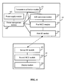
- the wireless temperature sensor further comprises a power supply module, and a power management module.
- the power supply module operates to supply power to modules of the wireless temperature sensor under a control of said power management module.
- the power management module operates to control the power supply module to supply or to stop supplying power to modules of the wireless temperature sensor.
- the first MCU module further operates to detect states of the modules of the wireless temperature sensor respectively, to inform the power management module to control the power supply module to supply power to modules in an operating state, and to inform the power management module to control the power supply module to stop supplying power to modules in an idle state.
- the wireless temperature sensor further comprises a power sensing module.
- the power sensing module operates to detect electric quantity of the power supply module, and to transmit a warning signal indicating low power to the first MCU module as electric quantity of the power supply module is less than a preset threshold value.
- the first MCU module further operates to receive the warning signal from the power sensing module, and to transmit the warning signal to the communication terminal via the first RF module.
- the wireless temperature sensor further comprises a reset circuit operating to provide a reset signal to the first MCU module once power is on.
- the communication terminal further comprises an input module operating to provide a man machine interface.
- the communication terminal further comprises a parallel switching module operating to dynamically switch between parallel circuits output from the communication terminal.
- the communication terminal further comprises an interface module operating to provide a communication interface.
- the wireless temperature measuring system further comprises a computer group.
- the computer group comprises a server and multiple computers operating to remotely monitor temperature.
- the server is connected to the communication terminal via the communication interface provided by the interface module, and the server is connected to the computer via a wide area network (WAN) or a local area network (LAN).
- WAN wide area network
- LAN local area network
- Advantages of the invention include: by collecting temperature at the temperature detection point by the wireless temperature sensor, and transmitting the temperature signal after performing cyclic-interleave and error-correction coding on the temperature signal, transmission distance of the RF module is increased such that one communication terminal is capable of managing up to hundreds of wireless temperature sensors and, in turn, centralized remote monitoring can be facilitated, no in-situ cable laying is required, installation is simple, extension is convenient, and the invention is not affected by sunshine or other illuminations.
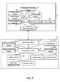
- a wireless temperature measuring system comprises multiple wireless temperature sensors 10, and multiple communication terminals 20.
- each of the communication terminal 20 communicates with multiple wireless temperature sensors 10 via radio frequency (RF) simultaneously.
- RF radio frequency
- the wireless temperature sensor 10 operates to obtain temperature signals from a temperature detection point, to perform cyclic-interleave and error-correction coding on the temperature signals whereby obtaining coded temperature signals, and to transmit the coded temperature signals to the communication terminal 20 via RF.
- the communication terminal 20 operates to receive and decode the coded temperature signals from the wireless temperature sensor 10, and to obtain and display decoded temperature signals.
- the wireless temperature sensor 10 comprises a temperature collection module 101, an analog/digital (A/D) conversion module 102, a first microcontroller unit (MCU) module 103, and a first RF module 104.
- A/D analog/digital
- MCU microcontroller unit
- the temperature collection module 101 operates to collect temperature of the temperature detection point whereby obtaining an analog temperature signal, to transmit the analog temperature signal to the A/D conversion module 102, and to transmit an ID number of the temperature collection module 101 to the first MCU module 103.
- Each of the temperature collection modules 101 has a unique ID number.
- an installation position of a temperature detection point corresponding to a wireless temperature sensor 10 is recorded and saved in the communication terminal 20 along with the ID number of the temperature collection module 101, so that upon receiving the temperature signal from the wireless temperature sensor 10, the communication terminal 20 can inquiry the installation position of the temperature detection point according to the ID number of the temperature collection module 101.
- the A/D conversion module 102 operates to receives the analog temperature signal from the temperature collection module 101, to perform A/D conversion on the analog temperature signal whereby obtaining a digital temperature signal, and to transmit the digital temperature signal to the first MCU module 103.
- the first MCU module 103 operates to receive the digital temperature signal from the A/D conversion module 102, and the ID number of the temperature collection module 101 from the temperature collection module 101, to pack the digital temperature signal and the ID number of the temperature collection module 101 with data frames whereby obtaining a temperature signal data packet, to perform cyclic-interleave and error-correction coding on the temperature signal data packet whereby obtaining a coded temperature signal, and to transmit the coded temperature signal to the first RF module 104.
- the cyclic-interleave and error-correction code is capable of correcting a continuous and bursting error of 24 bits, and a coding gain thereof is up to 3 dBm. And its error correction capability and coding efficiency achieves a leading position in the field, which is far higher than normal forward error correction. And the anti-interference capacity and sensitivity thereof also have a great improvement. Meanwhile, the cyclic-interleave and error-correction code has a performance of error detection so as to filter erroneous and false information, and thus greatly improving stability during data communication, and increasing transmission distance of the coded temperature signals upon transmitting via the first RF module 104.
- the communication terminal 20 is capable of receiving the temperature signal from the first RF module 104, which makes it possible to manage hundreds of wirelss temperature sensors 10 via one communication terminal 20. In this manner, only one communication terminal 20 is required in an application of electric power system to measure temperature and to receive the temperature signal from multiple wireless temperature sensors 10, and no wiring is needed.
- the first RF module 104 operates to receive the coded temperature signal from the first RF module 104, and to transmit the coded temperature signal to the communication terminal 20 via RF.
- the communication terminal 20 comprises a second RF module 201, a second MCU module 202, and a display module 203.
- the second RF module 201 operates to receive the coded temperature signal from the first RF module 104, and to transmit the coded temperature signal to the second MCU module 202.
- the second MCU module 202 operates to receive the coded temperature signal from the second RF module 201, to decode the coded temperature signal whereby obtaining a decoded temperature signal, and to transmit the decoded temperature signal to the display module 203.
- the display module 203 operates to receive and to display the decoded temperature signal from the second MCU module 202.
- the display module 203 may be a light emitting diode (LED) display, a liquid crystal display (LCD), and so on.
- LED light emitting diode
- LCD liquid crystal display
- the first MCU module 103 further operate to detect whether a RF signal exists at a main frequency point of the first RF module 104 after receiving the coded temperature signal, to transmit the coded temperature signal to the first RF module 104 and to inform the first RF module 104 to transmit the coded temperature signal via the main frequency point if no RF signal exists at the main frequency point of the first RF module 104, or to transmit the coded temperature signal to the first RF module 104 and to inform the first RF module 104 to transmit the coded temperature signal via an auxiliary frequency point if the RF signal exists at the main frequency point of the first RF module 104.
- the main frequency point is a default frequency point for transmitting the coded temperature signal.
- the main frequency point is 433 MHz.
- the auxiliary frequency point is used for transmission.
- auxiliary frequency points are used during application. As a RF signal exists at the main frequency point, the auxiliary frequency points are sequentially detected, and those with no RF signal thereat are used for transmitting the coded temperature signal. If RF signals exist at all the auxiliary frequency points, detection is performed from the main frequency point until a frequency point with no RF signal thereat is found. For example, three auxiliary points 433.1 MHz, 433.2 MHz, and 433.3 MHz are used.
- the first RF module 104 further operates to transmit the coded temperature signal to the communication terminal 20 via the main frequency point after receiving the coded temperature signal and a notice of transmitting the coded temperature signal via the main frequency point from the first MCU module 103, or to transmit the coded temperature signal to the communication terminal 20 via the auxiliary frequency point after receiving the coded temperature signal and a notice of transmitting the coded temperature signal via the auxiliary frequency point from the first MCU module 103.
- the second MCU module 202 further operates to set values of the main frequency point and the auxiliary frequency point, to pack the values of the main frequency point and the auxiliary frequency point with data frames whereby obtaining a frequency point packet, to perform cyclic-interleave and error-correction coding on the frequency point packet whereby obtaining a coded frequency point, and to transmit the coded frequency point to the second RF module 201.
- the second RF module 201 further operates to receive the coded frequency point from the second MCU module 202, and to transmit the coded frequency point to the first RF module 104 via RF.
- the first RF module 104 further operates to receive the coded frequency point from the second RF module 201, and to transmit the coded frequency point to the first MCU module 103.
- the first MCU module 103 further operates to receive the coded frequency point from the first RF module 104, to decode the coded frequency point whereby obtaining values of the main frequency point and the auxiliary frequency point, and to set the main frequency point and the auxiliary frequency point of the first RF module 104 according to the values of the main frequency point and the auxiliary frequency point.
- a main frequency point and multiple auxiliary frequency points can also be set, like the first RF module 104, and the method is the same as above and will not be described hereinafter.
- the first MCU module 103 further operates to detect whether the digital temperature signal matches a preset alarm temperature signal condition after receiving the digital temperature signal from the A/D conversion module, to pack the digital temperature signal and the ID number of the temperature collection module with data frames whereby obtaining a normal temperature signal packet, to perform cyclic-interleave and error-correction coding on the normal temperature signal packet whereby obtaining a coded normal temperature signal, and to transmit the coded normal temperature signal to the first RF module 104 according to a preset reporting period of the temperature signal if the digital temperature signal does not meet an alarm temperature signal condition, or to pack the digital temperature signal, the ID number of the temperature collection module, and a temperature alarm ID with data frames whereby obtaining an alarm temperature signal packet, to perform cyclic-interleave and error-correction coding on the alarm temperature signal packet whereby obtaining a coded alarm temperature signal, and to transmit the coded alarm temperature signal to the first RF module 104 if the digital temperature signal matches an alarm temperature signal condition.
- multiple temperature alarm modes such as high temperature alarm, low temperature alarm, temperature rise alarm, temperature reduction alarm, and so on, can be set.
- the preset alarm temperature signal condition can be set as: sending alarm as the digital temperature signal is higher or lower than a threshold value, or an increment or decrement reaches a threshold value.
- a reporting period of the temperature signal can be flexibly set according to an actual condition, such as 10 minutes, 1 hour and so on. That is, the wireless temperature sensors 10 do not need to transmit all of the collected temperature signals to the communication terminal.
- the wireless temperature sensor 10 reports temperature at the temperature detection point at the reporting period, such as every 10 minutes.
- the wireless temperature sensor 10 transmits the temperature signal to the communication terminal 20 in real-time.
- the first RF module 104 further operates to receive the coded normal temperature signal from the first MCU module 103, and to transmit the coded normal temperature signal to the communication terminal 20 via RF, or to receive the coded alarm temperature signal from the first MCU module 103, and to transmit the coded alarm temperature signal to the communication terminal 20 via RF.
- the communication terminal 20 further comprises an alarm module 204.
- the second RF module 201 further operates to receive the coded normal or alarm temperature signal from the first RF module 104, and to transmit the coded normal or alarm temperature signal to the second MCU module 202.
- the second MCU module 202 further operates to receive the coded normal temperature signal from the second RF module 201, to decode the normal temperature signal whereby obtaining a decoded normal temperature signal, and to transmit the decoded normal temperature signal to the display module 203, or to receive the coded alarm temperature signal from the second RF module 201, to decode the alarm temperature signal whereby obtaining a decoded alarm temperature signal, to transmit the decoded alarm temperature signal to the display module 203, and to inform the alarm module 204 to send an alarm.
- the alarm module 204 can use audible and visual alarm, and buzz alarm and so on.
- the display module 203 further operates to receive and to display the decoded normal temperature signal from the second MCU module 202, or to receive and to display the decoded alarm temperature signal from the second MCU module 202.
- the second MCU module 202 further operates to set the alarm temperature signal condition and the reporting period of the temperature signal, to pack the alarm temperature signal condition and the reporting period of the temperature signal with data frames respectively whereby obtaining an alarm temperature signal condition packet, and a reporting period packet, to perform cyclic-interleave and error-correction coding on the alarm temperature signal condition packet and the reporting period packet respectively whereby obtaining a coded alarm temperature signal condition and a coded reporting period, and to transmit the coded alarm temperature signal condition and the coded reporting period to the second RF module 201.
- the second RF module 201 further operates to receive the coded alarm temperature signal condition and the coded reporting period from the second MCU module 202, and to transmit the coded alarm temperature signal condition and the coded reporting period to the first RF module 104 via RF.
- the first RF module 104 further operates to receive the coded alarm temperature signal condition and the coded reporting period from the second RF module 201, and to transmit the coded alarm temperature signal condition and the coded reporting period to the first MCU module 103.
- the first MCU module 103 further operates to receive the coded alarm temperature signal condition and the coded reporting period from the first RF module 104, and to decode the coded alarm temperature signal condition and the coded reporting period whereby obtaining the alarm temperature signal condition and the reporting period of the temperature signal.
- a main frequency point and multiple auxiliary frequency points can also be set, like the first RF module 104, and the method is the same as above and will not be described hereinafter.
- the wireless temperature sensor 10 further comprises a power supply module 105, and a power management module 106.
- the power supply module 105 operates to supply power to modules of the wireless temperature sensor 10 under a control of the power management module 106.
- the power supply module 105 is a battery module, and any type of batteries can be used.
- the power management module 106 operates to control the power supply module 105 to supply or to stop supplying power to modules of the wireless temperature sensor 10.
- the first MCU module 103 further operates to detect states of the modules of the wireless temperature sensor 10 respectively, to inform the power management module 106 to control the power supply module 105 to supply power to modules in an operating state, and to inform the power management module 106 to control the power supply module 105 to stop supplying power to modules in an idle state.
- the first MCU module 103 detects states of itself, the temperature collection module 101, the A/D conversion module 102, and the first RF module 104.
- the first MCU module 103 informs the power management module 106 to control the power supply module 105 to supply power to the temperature collection module 101, the A/D conversion module 102, the first MCU module 103, or the first RF module 104.
- the first MCU module 103 informs the power management module 106 to control the power supply module 105 to stop supplying power to the temperature collection module 101, the A/D conversion module 102, the first MCU module 103, or the first RF module 104.
- the wireless temperature sensor 10 using the above-mentioned low power loss method can greatly increase work life of the power supply module 105.
- the reporting period of the temperature signal is 30 minutes, a work life of a 1800 mAh battery can be used for 8 to 10 years (3 years with a prior method).
- the wireless temperature sensor 10 further comprises a power sensing module 107.
- the power sensing module 107 operates to detect electric quantity of the power supply module 105, and to transmit a warning signal indicating low power to the first MCU module 103 as electric quantity of the power supply module 105 is less than a preset threshold.
- the first MCU module 103 further operates to receive the warning signal from the power sensing module 107, and to transmit the warning signal to the communication terminal 20 via the first RF module 104.
- the alarm module 204 sends an alarm or the display module 203 display the warning signal whereby informing a user to change a battery.
- the wireless temperature sensor 10 further comprises a reset circuit 108.
- the reset circuit 108 operates to provide a reset signal to the first MCU module 103 once power is on whereby ensuring reliable operation thereof.
- the communication terminal 20 further comprises an input module 205.
- the input module 205 operates to provide a man machine interface.
- the input module 205 may be a keyboard, a touch screen and so on.
- remote control of the wireless temperature sensor 10 is facilitated.
- the communication terminal 20 further comprises a parallel switching module 206.
- the parallel switching module 206 operates to dynamically switch between parallel circuits output from the communication terminal 20.
- the parallel switching module 206 is capable of switching from a parallel circuit to a RS-232 communication interface or a RS-485 communication interface.
- the RS-232 communication interface provides a program updating interface
- the RS-485 communication interface provides a communication interface.
- the communication terminal 20 further comprises a protection circuit 207, and a power transforming module 208.
- the protection circuit 207 operates to switch off a power supply as power supplied to the second MCU module 202 is higher than a preset threshold power value.
- the power transforming module 208 operates to transform power supplied to the second MCU module 202 by the protection circuit 207 into power that the second MCU module 202 needs.
- the operation that switch off a power supply as power supplied to the second MCU module 202 is higher than a preset threshold power value can protect the communication terminal 20, which makes the invention applicable to severe industrial environment, and effectively protects the invention against thunder and light, over-voltage, over-current, and so on.
- the communication terminal 20 further comprises a voltage-monitoring module 209.
- the voltage-monitoring module 209 operates to monitor power voltage of the second MCU module 202, and to provide a reset signal to the second MCU module 202 as the power voltage drops.
- the communication terminal 20 further comprises a back-light adjustment module 210.
- the back-light adjustment module 210 operates to adjust back light of the display module 203.
- the communication terminal 20 further comprises an interface module 211.
- the interface module 211 operates to provide a communication interface.
- the communication interface may be a general packet radio service (GPRS) interface, a code division multiple access (CDMA) interface, a RS-485 bus, an Ethernet interface, a fiber interface, and so on.
- GPRS general packet radio service
- CDMA code division multiple access
- RS-485 RS-485 bus
- Ethernet Ethernet interface
- fiber interface a fiber interface
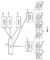
- the wireless temperature measuring system further comprises a computer group 30.
- the computer group 30 comprises a server 301 and multiple computers 302 which operate to remotely monitor temperature.
- the server 301 is connected to the communication terminal 20 via the communication interface provided by the interface module 211, and to the computer 302 via a wide area network (WAN) or a local area network (LAN).
- WAN wide area network
- LAN local area network
- the server 301 obtains temperature data at all temperature detection points from the communication terminal 20, saves the temperature data in database for a long time, displays a temperature variation curve of the temperature detection point in real-time, and can access a web for web publishing.
- the computer 302 can visit the server 301 via the Internet Explorer.
- the communication terminal 20 can be an economical receiver, an intelligent receiver or other equivalent devices.
- the server 301 is capable of displaying real-time temperature data and highest temperature data, inquiring history data in a certain time period, drawing curves, and graphically indicating variation of state variables.
- the server 301 can adjust temperature alarm threshold value and measuring time of the wireless temperature sensor 10, and provide a wireless WEB-based temperature inquiry system during WEB publishing. Temperature data are published on the server 301. All computers in the computer group 30 can enter the inquiry system with allocated authority and passwords whereby implementing data inquiry, analysis of a temperature trend curve, real-time monitoring of electric maps, device management, staff authority management, and so on.
- the server 301 also can be used to set functional parameters of the wireless temperature sensor 10, such as values of the main frequency point and the auxiliary frequency point, the alarm temperature signal condition, the reporting period of the temperature signal, and so on, and to transmit them to the wireless temperature sensor 10 via the communication terminal 20.
- the wireless temperature measuring system of the invention can be applied to industry, military, electric power and so on.
- the temperature detection point is disposed at a joint of cables that easily get hot, or at surface of transformers and switches.
- the communication terminal 20 is disposed in a central control room for receiving temperature data from the wireless temperature sensor 10, or connected to the server 301 of the computer group 30 via buses whereby uploading temperature data thereto and responding to various commands therefrom.
- Multiple computers 302 can log on the server 301 to obtain temperature information, and set control commands according different authority.
- the wireless temperature sensor 10 is randomly disposed in a user's home. As the wireless temperature sensor 10 collects temperature data, data are transmitted via RF. Every wireless temperature sensor 10 has a unique ID number, and all the wireless temperature sensors 10 transmit data in a manner of automatic routing and relay.
- the communication terminal 20 or the computer group 30 adjusts transmission time and period of the temperature signal and alarm temperature threshold thereof of the wireless temperature sensor 10, whereby implementing bi-directional communication.
- the wireless temperature sensor 10 employs low power consumption design, power is supplied thereto via batteries, and work life of the batteries is 8 to 10 years.
- the wireless temperature sensor 10 automatically transmits temperature data in a certain time interval, and sends alarm as temperature is abnormal without limitation of transmission time.
- the communication terminal 20 receives the temperature data from wireless temperature sensor 10 via RF and the display module (such as LED) displays the temperature data.
- the display module such as LED
- a user is capable of setting parameters of the wireless temperature sensor 10 via the input module 205.
- the communication interface of the communication terminal 20 communicates with the server 301 via a RS-485 bus, a GPRS interface, an Ethernet interface, a fiber interface, and so on.
- Background software of the wireless temperature measuring system is installed on the server 301, whereby implementing monitoring of real-time temperature, highest temperature, lowest temperature, average temperature and so on, intelligently analyzing the temperature data according to preset time interval or inquiry condition in a manner of a bar chart or a trend curve, and setting a sampling interval and various alarm threshold values (comprising increment or decrement of temperature, absolute temperature, and so on).
- Software of the invention publishes database on the server 301 via WEB publishing, so that authorized computers in the LAN can browse the temperature data and relevant graphs, and remotely change various parameters.
- the wireless temperature measuring system collects temperature at the temperature detection point by the wireless temperature sensor, and transmits the temperature signal after performing cyclic-interleave and error-correction coding on the temperature signal, which makes the transmission distance is increased when the coded temperature signal is transmitted via the RF module such that one communication terminal is capable of managing up to hundreds of wireless temperature sensors and, in turn, centralized remote monitoring can be facilitated, no in-situ cable laying is required, installation is simple, extension is convenient, and the invention is not affected by sunshine or other illuminations.
- the auxiliary frequency point can be used for transmission such that same frequency interference is avoided.
- a temperature signal can be transmitted to the communication terminal according to a preset reporting period of the temperature signal, which can save the signal transmition between the wireless temperature sensor and the communication terminal. If the digital temperature signal matches an alarm temperature signal condition (the temperature is abnormal), an alarm is sent immediately without limitation of transmition period.
- the power is supplied to the modules in operating state of the wireless temperature sensor, which can save the power of the power supply module and increase work life of the power supply module.
- All or part of the content of the invention can be facilitated by software programming, and relevant software programs are saved in readable storage mediums, such as hard disks, CDs, or floppy disks.
Landscapes
- Engineering & Computer Science (AREA)
- Computer Networks & Wireless Communication (AREA)
- Physics & Mathematics (AREA)
- General Physics & Mathematics (AREA)
- Arrangements For Transmission Of Measured Signals (AREA)
Applications Claiming Priority (2)
| Application Number | Priority Date | Filing Date | Title |
|---|---|---|---|
| CN2009202298077U CN201936433U (zh) | 2009-11-16 | 2009-11-16 | 远程室温实时监测装置 |
| PCT/CN2010/076666 WO2011057517A1 (zh) | 2009-11-16 | 2010-09-07 | 一种无线测温系统 |
Publications (2)
| Publication Number | Publication Date |
|---|---|
| EP2503528A1 true EP2503528A1 (de) | 2012-09-26 |
| EP2503528A4 EP2503528A4 (de) | 2017-09-20 |
Family
ID=43991194
Family Applications (1)
| Application Number | Title | Priority Date | Filing Date |
|---|---|---|---|
| EP10829481.0A Withdrawn EP2503528A4 (de) | 2009-11-16 | 2010-09-07 | Drahtloses temperaturmesssystem |
Country Status (4)
| Country | Link |
|---|---|
| US (1) | US8981943B2 (de) |
| EP (1) | EP2503528A4 (de) |
| CN (1) | CN201936433U (de) |
| WO (1) | WO2011057517A1 (de) |
Cited By (2)
| Publication number | Priority date | Publication date | Assignee | Title |
|---|---|---|---|---|
| CN105302049A (zh) * | 2015-12-03 | 2016-02-03 | 广州供电局有限公司 | 变电站环境监测装置 |
| CN107246926A (zh) * | 2017-07-04 | 2017-10-13 | 安徽鹰峰电子科技有限公司 | 一种快速多通道温度传感器编码系统及方法 |
Families Citing this family (34)
| Publication number | Priority date | Publication date | Assignee | Title |
|---|---|---|---|---|
| GB201102628D0 (en) | 2011-02-15 | 2011-03-30 | Nordic Semiconductor Asa | Programmable radio |
| CN102279063B (zh) * | 2011-06-17 | 2013-01-09 | 明高五金制品(深圳)有限公司 | 一种烧烤温度监测设备及系统 |
| CN102313316B (zh) * | 2011-09-06 | 2013-08-07 | 北京同方瑞博数字技术有限公司 | 集中供暖的室内温度实时自动监测、监控、控制的系统 |
| CN102519614B (zh) * | 2011-12-09 | 2014-03-12 | 北京百纳威尔科技有限公司 | 温度测量装置、方法及系统 |
| CN102589722A (zh) * | 2012-02-23 | 2012-07-18 | 天津工业大学 | 温度检测系统 |
| EP2650191B1 (de) | 2012-04-12 | 2019-01-16 | Progress Rail Services Corporation | Verfahren zum Erkennen und Signalisieren eines Hotbox-Zustands |
| EP2650190A1 (de) * | 2012-04-12 | 2013-10-16 | Progress Rail Services Corporation | Vorrichtung zum Erkennen eines Hotbox- oder eines heißen Reifenzustands |
| US8931952B2 (en) * | 2012-04-27 | 2015-01-13 | Par Technology Corporation | Temperature monitoring device for workflow monitoring system |
| US9970822B2 (en) | 2012-04-27 | 2018-05-15 | Par Technology Corporation | Temperature monitoring device for workflow monitoring system |
| CN102945250B (zh) * | 2012-10-11 | 2016-09-28 | 广西电网公司电力科学研究院 | 一种在线式红外数据处理方法 |
| CN103196487A (zh) * | 2013-03-06 | 2013-07-10 | 乐清市供电局 | 一种温湿度监测装置及方法 |
| ES2537887B1 (es) * | 2013-12-13 | 2016-04-12 | Luis Miguel MOLINA ALARCÓN | Sistema de medición remota para uno o varios sensores térmicos analógicos |
| CN103750826A (zh) * | 2013-12-25 | 2014-04-30 | 杨松 | 无线无源测量温度的方法、系统及组成该系统的装置 |
| CN104330701B (zh) * | 2014-11-06 | 2017-05-24 | 扬州森源电气有限公司 | 一种小区用单相故障监测无线系统及其监测方法 |
| CN104792020A (zh) * | 2014-11-10 | 2015-07-22 | 广东万和新电气股份有限公司 | 燃气采暖炉智能控制装置 |
| CN106153204A (zh) * | 2015-04-26 | 2016-11-23 | 於晓明 | 具有无线通讯功能的温度测量装置及方法 |
| US10451489B2 (en) * | 2015-07-10 | 2019-10-22 | The Charles Stark Draper Laboratory, Inc. | Thermal event sensor |
| CN106506576B (zh) * | 2015-09-08 | 2019-12-17 | 姜殿威 | 超导磁共振外围设备的监控系统及监控方法 |
| CN105547520A (zh) * | 2015-12-15 | 2016-05-04 | 杭州万联网络科技有限公司 | 无线温度监测系统以及监测点的布设选取方法 |
| CN105403319A (zh) * | 2015-12-24 | 2016-03-16 | 安徽中电兴发与鑫龙科技股份有限公司 | 一种智能化温度巡检仪 |
| EP3414541B1 (de) * | 2016-02-08 | 2020-09-30 | Watlow Electric Manufacturing Company | Temperaturerfassungssystem für eine drehbare wafer-trägeranordnung |
| CN105872276A (zh) * | 2016-03-23 | 2016-08-17 | 哈尔滨工程大学 | 一种基于拨打电话的温度快速查询装置及查询方法 |
| CN105719465A (zh) * | 2016-04-25 | 2016-06-29 | 深圳市华茂欧特科技有限公司 | 一种基于混合无线网络的远程数据监测系统 |
| CN106768407A (zh) * | 2016-11-28 | 2017-05-31 | 广西大学 | 一种干式电抗器无线温度在线监测装置 |
| CN106768479A (zh) * | 2016-11-29 | 2017-05-31 | 国网辽宁省电力有限公司沈阳供电公司 | 反射高能电子衍射谱实现对电缆温升的在线测量检测装置 |
| CN107861597A (zh) * | 2017-11-30 | 2018-03-30 | 无锡中微爱芯电子有限公司 | 一种应用于mcu复位系统中的抗干扰设计方法 |
| CN108593131A (zh) * | 2018-05-10 | 2018-09-28 | 东莞市诺丽电子科技有限公司 | 一种轴温传感器电路 |
| CN109668637A (zh) * | 2018-06-29 | 2019-04-23 | 浙江巨感物联网科技有限公司 | 一种无线联网型电气线缆温度隐患预警系统及方法 |
| CN111491268B (zh) * | 2020-03-09 | 2022-10-04 | 江苏经贸职业技术学院 | 一种针对物流管理的感测方式和装置 |
| CN112665729A (zh) * | 2020-12-24 | 2021-04-16 | 杭州凯达电力建设有限公司 | 一种基于LoRa通讯的远距离输电线在线测温系统 |
| CN113053059A (zh) * | 2021-03-17 | 2021-06-29 | 北京融安特智能科技股份有限公司 | 信息显示方法、装置、计算设备及存储介质 |
| US20250116454A1 (en) * | 2021-09-14 | 2025-04-10 | Panasonic Intellectual Property Management Co., Ltd. | Inspection device and inspection system for cold insulator |
| CN114979825A (zh) * | 2022-05-16 | 2022-08-30 | 盐城师范学院 | 一种基于无线通信的数据采集系统 |
| WO2024150296A1 (ja) * | 2023-01-11 | 2024-07-18 | 日本電信電話株式会社 | センサデータ収集システムおよび方法 |
Family Cites Families (19)
| Publication number | Priority date | Publication date | Assignee | Title |
|---|---|---|---|---|
| US4278841A (en) * | 1979-10-22 | 1981-07-14 | Jack Regennitter | Multiple station temperature monitor system |
| FR2688914B1 (fr) * | 1992-02-06 | 1994-09-23 | Michel Leprieur | Procede et transfert de mesure de temperature ou d'hygrometrie sans fil. |
| FR2712405B1 (fr) * | 1993-11-09 | 1999-06-18 | Cedom Sa | Dispositif de mesure et de régulation d'ambiance à transmission hertzienne. |
| US6300871B1 (en) * | 1997-11-12 | 2001-10-09 | Headwaters Research & Development, Inc. | Multi-station RF thermometer and alarm system |
| WO2000021053A1 (en) * | 1998-10-06 | 2000-04-13 | Slc Technologies, Inc. | Wireless home fire and security alarm system |
| CN2366839Y (zh) * | 1999-02-04 | 2000-03-01 | 浙江大学工业自动化工程研究中心 | 蒸球温度自动连续测量装置 |
| CA2314573C (en) * | 2000-01-13 | 2009-09-29 | Z.I. Probes, Inc. | System for acquiring data from a facility and method |
| US7034711B2 (en) * | 2001-08-07 | 2006-04-25 | Nsk Ltd. | Wireless sensor, rolling bearing with sensor, management apparatus and monitoring system |
| CN1552281A (zh) * | 2003-06-04 | 2004-12-08 | 娜 朱 | 无线集中监测群体体温的方法和系统 |
| US7766826B2 (en) * | 2003-11-26 | 2010-08-03 | Medtronic, Inc. | Multi-level averaging scheme for acquiring hemodynamic data |
| US7091854B1 (en) * | 2004-04-09 | 2006-08-15 | Miao George J | Multiple-input multiple-output wireless sensor networks communications |
| US7142107B2 (en) * | 2004-05-27 | 2006-11-28 | Lawrence Kates | Wireless sensor unit |
| WO2006101490A1 (en) * | 2005-03-18 | 2006-09-28 | Lawrence Richman | Human guard enhancing multiple site security system |
| JP4537248B2 (ja) * | 2005-04-06 | 2010-09-01 | 富士通株式会社 | キャリアセンス方法及び送受信装置 |
| JP4773510B2 (ja) * | 2006-03-28 | 2011-09-14 | 株式会社日立製作所 | センサネットシステム、センサネットシステムデータ管理方法、センサネットシステムデータ管理プログラム |
| CN201015058Y (zh) * | 2007-01-08 | 2008-01-30 | 山西恒发电子有限公司 | 高压线路接点温度无线监测系统 |
| JP2009033622A (ja) * | 2007-07-30 | 2009-02-12 | Kyocera Corp | Ofdm送信装置及びofdm受信装置並びにインターリーブ方法 |
| FI20085423A0 (fi) * | 2008-05-08 | 2008-05-08 | Nokia Siemens Networks Oy | Synkronointi matkaviestinjärjestelmässä |
| CN101319938B (zh) * | 2008-07-08 | 2010-04-07 | 周骁威 | 高压设备电缆接头的在线测温方法及其装置 |
-
2009
- 2009-11-16 CN CN2009202298077U patent/CN201936433U/zh not_active Expired - Fee Related
-
2010
- 2010-09-07 EP EP10829481.0A patent/EP2503528A4/de not_active Withdrawn
- 2010-09-07 WO PCT/CN2010/076666 patent/WO2011057517A1/zh not_active Ceased
- 2010-11-23 US US12/953,428 patent/US8981943B2/en not_active Expired - Fee Related
Non-Patent Citations (1)
| Title |
|---|
| See references of WO2011057517A1 * |
Cited By (3)
| Publication number | Priority date | Publication date | Assignee | Title |
|---|---|---|---|---|
| CN105302049A (zh) * | 2015-12-03 | 2016-02-03 | 广州供电局有限公司 | 变电站环境监测装置 |
| CN107246926A (zh) * | 2017-07-04 | 2017-10-13 | 安徽鹰峰电子科技有限公司 | 一种快速多通道温度传感器编码系统及方法 |
| CN107246926B (zh) * | 2017-07-04 | 2023-08-29 | 安徽鹰峰电子科技有限公司 | 一种快速多通道温度传感器编码系统及方法 |
Also Published As
| Publication number | Publication date |
|---|---|
| EP2503528A4 (de) | 2017-09-20 |
| WO2011057517A1 (zh) | 2011-05-19 |
| US20110115636A1 (en) | 2011-05-19 |
| CN201936433U (zh) | 2011-08-17 |
| US8981943B2 (en) | 2015-03-17 |
Similar Documents
| Publication | Publication Date | Title |
|---|---|---|
| EP2503528A1 (de) | Drahtloses temperaturmesssystem | |
| JP5791596B2 (ja) | 電力監視システム | |
| AU2012100135A4 (en) | Power sensor | |
| AU2012100197A4 (en) | Power sensor | |
| CN102023253A (zh) | 防雷监测报警系统 | |
| AU2011101402C4 (en) | Power monitoring system with remote sensing and alerting | |
| EP1946279A2 (de) | Automatische detektion eines ungewöhnlichen verbrauchs durch einen versorgungszähler | |
| CN209745428U (zh) | 一种电缆在线监测装置 | |
| CN113093048B (zh) | 铁路隧道应急照明及疏散指示装置运维状态智能监测系统 | |
| CN114839911A (zh) | 一种基于电量采集数据的可视化监控系统及管理方法 | |
| CN113763692A (zh) | 一种具有电池电量提示功能的遥控器 | |
| AU2011101409A4 (en) | Power monitoring system with remote sensing and alerting | |
| AU2011101388A4 (en) | Power monitoring system with remote sensing | |
| AU2011101408B4 (en) | Power monitoring system with remote sensing and alerting | |
| AU2011100848B4 (en) | Power monitoring system | |
| CN121475353A (zh) | 一种阀控水表及阀门控制方法 | |
| TW201511602A (zh) | 行動基地台用電異常偵測方法 |
Legal Events
| Date | Code | Title | Description |
|---|---|---|---|
| PUAI | Public reference made under article 153(3) epc to a published international application that has entered the european phase |
Free format text: ORIGINAL CODE: 0009012 |
|
| 17P | Request for examination filed |
Effective date: 20120618 |
|
| AK | Designated contracting states |
Kind code of ref document: A1 Designated state(s): AL AT BE BG CH CY CZ DE DK EE ES FI FR GB GR HR HU IE IS IT LI LT LU LV MC MK MT NL NO PL PT RO SE SI SK SM TR |
|
| DAX | Request for extension of the european patent (deleted) | ||
| RA4 | Supplementary search report drawn up and despatched (corrected) |
Effective date: 20170818 |
|
| RIC1 | Information provided on ipc code assigned before grant |
Ipc: G01K 1/02 20060101AFI20170811BHEP Ipc: H04Q 9/00 20060101ALI20170811BHEP |
|
| STAA | Information on the status of an ep patent application or granted ep patent |
Free format text: STATUS: THE APPLICATION IS DEEMED TO BE WITHDRAWN |
|
| 18D | Application deemed to be withdrawn |
Effective date: 20180316 |