EP2503418A2 - Steuersystem mit Zustandserfassung und -wiederherstellung - Google Patents
Steuersystem mit Zustandserfassung und -wiederherstellung Download PDFInfo
- Publication number
- EP2503418A2 EP2503418A2 EP12159366A EP12159366A EP2503418A2 EP 2503418 A2 EP2503418 A2 EP 2503418A2 EP 12159366 A EP12159366 A EP 12159366A EP 12159366 A EP12159366 A EP 12159366A EP 2503418 A2 EP2503418 A2 EP 2503418A2
- Authority
- EP
- European Patent Office
- Prior art keywords
- controller
- state
- volatile memory
- captured
- workstation
- Prior art date
- Legal status (The legal status is an assumption and is not a legal conclusion. Google has not performed a legal analysis and makes no representation as to the accuracy of the status listed.)
- Withdrawn
Links
- 238000000034 method Methods 0.000 claims abstract description 43
- 238000012544 monitoring process Methods 0.000 claims abstract description 8
- 230000008569 process Effects 0.000 claims description 30
- 238000010248 power generation Methods 0.000 claims description 10
- 238000004088 simulation Methods 0.000 description 20
- 101000720958 Homo sapiens Protein artemis Proteins 0.000 description 4
- 102100025918 Protein artemis Human genes 0.000 description 4
- 238000010586 diagram Methods 0.000 description 4
- 238000004891 communication Methods 0.000 description 3
- 230000001276 controlling effect Effects 0.000 description 3
- 238000004519 manufacturing process Methods 0.000 description 3
- 230000004044 response Effects 0.000 description 3
- 230000008901 benefit Effects 0.000 description 2
- 238000013461 design Methods 0.000 description 2
- 238000011161 development Methods 0.000 description 2
- 230000000694 effects Effects 0.000 description 2
- 238000002347 injection Methods 0.000 description 2
- 239000007924 injection Substances 0.000 description 2
- 101000847066 Homo sapiens Translin-associated protein X Proteins 0.000 description 1
- 102100032834 Translin-associated protein X Human genes 0.000 description 1
- 239000002253 acid Substances 0.000 description 1
- 230000009471 action Effects 0.000 description 1
- 230000006399 behavior Effects 0.000 description 1
- 230000008859 change Effects 0.000 description 1
- 239000002826 coolant Substances 0.000 description 1
- 239000003085 diluting agent Substances 0.000 description 1
- 239000012530 fluid Substances 0.000 description 1
- 239000000446 fuel Substances 0.000 description 1
- ZZUFCTLCJUWOSV-UHFFFAOYSA-N furosemide Chemical compound C1=C(Cl)C(S(=O)(=O)N)=CC(C(O)=O)=C1NCC1=CC=CO1 ZZUFCTLCJUWOSV-UHFFFAOYSA-N 0.000 description 1
- 239000004973 liquid crystal related substance Substances 0.000 description 1
- 239000000463 material Substances 0.000 description 1
- 238000005457 optimization Methods 0.000 description 1
- 238000012545 processing Methods 0.000 description 1
- 230000002250 progressing effect Effects 0.000 description 1
- 238000011084 recovery Methods 0.000 description 1
- 230000007363 regulatory process Effects 0.000 description 1
- 238000000926 separation method Methods 0.000 description 1
- 238000003860 storage Methods 0.000 description 1
- XLYOFNOQVPJJNP-UHFFFAOYSA-N water Substances O XLYOFNOQVPJJNP-UHFFFAOYSA-N 0.000 description 1
Images


Classifications
-
- G—PHYSICS
- G05—CONTROLLING; REGULATING
- G05B—CONTROL OR REGULATING SYSTEMS IN GENERAL; FUNCTIONAL ELEMENTS OF SUCH SYSTEMS; MONITORING OR TESTING ARRANGEMENTS FOR SUCH SYSTEMS OR ELEMENTS
- G05B19/00—Programme-control systems
- G05B19/02—Programme-control systems electric
- G05B19/04—Programme control other than numerical control, i.e. in sequence controllers or logic controllers
- G05B19/042—Programme control other than numerical control, i.e. in sequence controllers or logic controllers using digital processors
- G05B19/0428—Safety, monitoring
-
- G—PHYSICS
- G05—CONTROLLING; REGULATING
- G05B—CONTROL OR REGULATING SYSTEMS IN GENERAL; FUNCTIONAL ELEMENTS OF SUCH SYSTEMS; MONITORING OR TESTING ARRANGEMENTS FOR SUCH SYSTEMS OR ELEMENTS
- G05B2219/00—Program-control systems
- G05B2219/20—Pc systems
- G05B2219/24—Pc safety
- G05B2219/24102—Display status of controller
-
- G—PHYSICS
- G05—CONTROLLING; REGULATING
- G05B—CONTROL OR REGULATING SYSTEMS IN GENERAL; FUNCTIONAL ELEMENTS OF SUCH SYSTEMS; MONITORING OR TESTING ARRANGEMENTS FOR SUCH SYSTEMS OR ELEMENTS
- G05B2219/00—Program-control systems
- G05B2219/20—Pc systems
- G05B2219/24—Pc safety
- G05B2219/24119—Compare control states to allowed and forbidden combination of states
Definitions
- the subject matter disclosed herein relates to control systems, and, more specifically, to configuring programmable controllers.
- Control systems for processes, plants, and equipment may include a wide variety of logic to configure how the control system monitors and controls the processes, plants and equipment.
- a control system may include one or more programmable controllers. In certain applications, the control system may include a redundant configuration of two, three, or more programmable controllers. Each controller may execute logic designed to monitor and control the process, plant, and/or equipment controlled by the controller. The controllers may be changed to optimize the process, plants, and equipment. Additionally, it may be useful to perform root cause analysis (RCA) and other analysis routines on the controllers in the event of unexpected behavior of the process, plants, or equipment or for diagnostic purposes.
- RCA root cause analysis
- a method includes receiving a command to save a state of a controller coupled to an industrial system, wherein the controller comprises a processor and a non-volatile memory, capturing the state of the controller during control and monitoring of the industrial system, and writing the captured state to the non-volatile memory of the controller
- a system in a second embodiment, includes a controller that includes a processor and a non-volatile memory coupled to the processor.
- the non-volatile memory comprises instructions for capturing the state of the controller, wherein the controller controls and monitors an industrial system coupled to the controller and writing the captured state to the non-volatile memory of the controller, wherein the captured state comprises state variables and process variables of the controller
- a method in a third embodiment, includes providing a command to a controller to capture a state of the controller, copying the captured state from the controller to a workstation, loading the captured state in a simulation of a virtual controller, wherein the virtual controller emulates the controller, and executing the simulation in the virtual controller.
- Embodiments of the present invention include a control system that captures the state of a controller during control and monitoring of a system.
- the captured state may include process variables, state variables, diagnostic information, event information, and alarm information.
- the captured state may be stored on a non-volatile memory of the controller.
- the captured state may be copied from one platform to another platform, such as a workstation.
- the captured state may be loaded in a virtual controller and simulation executing on the workstation.
- a model state appropriate for the captured state may be loaded from a database and a simulation of the captured state may be performed.
- FIG. 1 depicts an industrial system 10, e.g., a plant, coupled to a control system 12 in accordance with an embodiment of the present invention.
- the system 10 may include, for example, a process 14, a turbine 16, a power generation component 18, or any other component or combination thereof.
- the system 10 may include a gasifier, a gas treatment system, (e.g., acid gas removal), an air separation unit, or other process or components.
- the process 14 may comprise a variety of operational components, such as electric motors, valves, actuators, sensors, or a myriad of manufacturing, processing, material handling and other applications. Further, the process 14 may comprise control and monitoring equipment for regulating process variables through automation and/or observation.
- the turbine 16 may include a steam turbine, a gas turbine, a wind turbine, a hydro turbine, or any combination thereof.
- the turbine 16 may include a combined cycle having a gas turbine, a steam turbine, and a heat recovery steam generation (HRSG) system.
- the turbine 16 may drive the power generation component 18, which may include an electrical generator or a mechanical drive such as a compressor.
- the turbine 14 and/or the power generation component may be solar-powered.
- the turbine 16 and power generation component 18 may include any number of operational components, such as motors, rotary components, power electronics, sensors, actuators, etc.
- the illustrated process 14, turbine 16, and power generation component 18 may include any number of sensors 20 and actuators/motors 22.
- the sensors 20 may comprise any number of devices adapted to provide information regarding process conditions.
- the sensors 20 may monitor temperature, pressure, speed, fluid flow rate, vibration, noise, exhaust emissions, power output, clearance, or any other suitable parameter
- the actuators 22 may similarly include any number of devices adapted to perform a mechanical action in response to an input signal.
- the actuators 22 may control a fuel injection rate, a diluent or water injection rate, a coolant rate, a power output level, a speed, a flow rate, a clearance, and so forth
- the control system 12 may include one, two, three, or more controllers 26 (e.g., programmable logic controllers) that may operate in any manner suitable for monitoring and controlling the system 10.
- FIG. 1 depicts a system having three controllers, Controller 1, Controller 2, and Controller 3.
- the controllers 26 may also be referred to as "real-time controllers," wherein a real-time controller is a tangible and physical controller having the components described below in FIG. 2 for real-time control and monitoring of an industrial system.
- the sensors 20 and actuators 22 may be in direct communication with any or all of the controllers 26 through the input/outputs 24.
- the input/outputs 24 may be packs, cards, or other devices coupled to or integral with the controllers 26. Additionally, the input/outputs 24 may be coupled to and communicate with the controller through suitable components, such as a network (e.g., Ethernet) and switches. These devices may be utilized to operate process equipment. Indeed, they may be utilized within process loops that are monitored and controlled by the control system 12 and the controllers 26.
- the controllers 26 may be separate and/or integral with the process 14, the turbine 16, and/or the power generation component 18.
- the control system 12 may be a Mark VIe control system manufactured by General Electric Company of Salem, Virginia.
- control system 12 may be coupled to and communicate with one or more work stations 28.
- the work stations 28 may include a desktop, laptop, or any other suitable electronic device.
- the workstations 28 may be coupled to the control system 12 through a wired or wireless network 30, such as wired or wireless Ethernet.
- the workstations 28 may be used as a human-machine interface (HMI) for the control system 12 may enable an operator or engineer to configure and, monitor the components of the control system 12, such as the controllers 26 and the input/outputs 24.
- HMI human-machine interface
- FIG. 2 depicts various components of one of the controllers 26 in accordance with an embodiment of the present invention.
- the controller 26 may include a processor 32, a network device 34, ports 36, a status display 38, volatile memory 40, and non-volatile memory 42.
- the processor 32 may execute instructions for operation of the controller 26, such as instructions stored in the volatile memory 40 and non-volatile memory 42.
- the network device 34 may include one or more network devices for communication with the workstations 28, input/outputs 24, and the other controllers 26.
- the network device 34 may include one or more wired or wireless Ethernet devices.
- the ports 36 may include ports for physically connecting the controller 26 to other devices.
- the ports may include Ethernet ports, USB ports, COM ports, etc.
- the status display 38 may include a display for indicating the status of the controller 26 and may include light-emitting diodes (LEDs), liquid crystal displays (LCDs), and OLED displays.
- LEDs light-emitting diodes
- LCDs liquid crystal displays
- the controller 26 may include volatile memory 40 and non-volatile memory 42.
- the volatile memory 40 may include random access memory (RAM), such as DRAM.
- the non-volatile memory 42 may include flash memory, phase change memory, resistive memory, or any other suitable non-volatile memory. Additionally, in some embodiments the non-volatile memory 42 may include magnetic storage devices such as hard drives, tape drives, etc.
- the non-volatile memory 42 may, in response to a state capture operation of the controller 26, store the captured state information. The state information may be later accessed from the non-volatile memory 42 by the controller 26 or by other devices, such as the workstation 28.
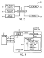
- FIG. 3 depicts capture of the state of the controller 26 in accordance with an embodiment of the present invention.
- the captured state may be saved from one platform, e.g., the controller 26, to another platform, e.g., the workstation 28.
- the controller 26 may receive/send data from/to the various controlled components of the system 10, such as from the sensor 20 and actuators 22 of the process 14, turbine 16, and/or power generation 18, through the inputs/outputs 24.
- the processor 32 of the controller 26 may write state information to the volatile memory 40 and then later write the state information to the non-volatile memory 42 to save a captured state 44.
- the "capture state” may be received over a wired or wireless network, such as through the network device 34.
- the capturing of the state may be performed during the process of a reboot of the controller 26.
- the state information may be first written to the non-volatile memory 42 without writing the state information in the volatile memory 40.
- the state capture may occur during operation of the controller 26 without rebooting the controller 26.
- the captured stated 44 may include the data received by the controller 26 from the components of the system 10.
- the captured state 44 may also include operational information from the controller 26, such as information that may be stored in volatile memory 40 and used by controller 26 to control and monitor the system 10.
- the captured state 44 may include process variables, state variables, event information, control constants information, diagnostic information, and alarm information.
- the captured state 44 may be saved as a file for copying to another platform.
- the volatile memory 40 and/or non-volatile memory 42 may also include a buffer that stores commands executed by the controller 26.
- the commands may also be captured in the captured state 44 and, as described below, the commands may be replayed in a simulation on a virtual controller.
- the captured state 44 may be time-tagged to include the date and time of the captured information.
- the states may be continuously captured to produce continuous captured states. The continuous captured states may be replayed in a virtual controller to analyze the different states over a time interval.
- FIG. 4 depicts saving of the captured state between the controller 26 and the workstation 28 in accordance with an embodiment of the present invention.
- the non-volatile memory 42 may store a captured state 44 that includes state information of the controller 26.
- the captured state 44 may be accessed by the workstation 28 for analysis and/or simulation.
- the workstation 28 may include a processor 46, volatile memory 48, and non-volatile memory 50, as well as other components such as display, input devices, etc.
- the workstation 28 may store and execute a virtual controller 52, i.e., a software emulation of the controller 26.
- the virtual controller 52 may emulate the controller 26 on the workstation 28 and may execute simulations of the system 10.
- the virtual controller 52 is a Mark VIe virtual control manufactured by General Electric Company of Salem, Virginia.
- the virtual controller 52 may be combined with other simulation software, such as ARTEMIS manufactured by General Electric Company of Salem, Virginia
- the workstation 28 may access (e.g., copy) the captured state 44 stored on the controller 26.
- the captured state 44 may be restored in the virtual controller 52 executing on the workstation 28.
- ARTEMIS may also load a model state 53 that matches the captured state 44 from a database 54.
- a simulation executing in ARTEMIS may use the captured state 44 in the Virtual Controller 52 and the model state 53 in a modeling environment to progress the simulation for analysis of the simulation in view of the captured state 44.
- other simulation software may be used, such as ProTRAX manufactured by TRAX International of Las Vegas, Nevada.
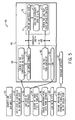
- FIG. 5 depicts a process 60 for capturing the state of the controller 26 and restoring the state in the virtual controller 52 in accordance with an embodiment of the present invention.
- Some or all of the process 60 may be implemented in non-transitory tangible computer-readable media, such as the volatile memory 40 and/or non-volatile memory 42 of the controller 26 and the volatile memory 48 and non-volatile memory 50 of the workstation 28.
- model states for different systems may be generated and saved in the database 52 (block 62).
- the model states may be based on specific parameters of interest and may include different states for the process, turbines, and power generation systems.
- the model states may correspond to multiple modeling environments and may be used on multiple workstations.
- the controller 26 of the control system 12 may be verified to be in a controlling state (block 64). If the controller 26 is in the controlling state, the state of the controller 26 may be captured (block 66), as further illustrated in expanded block 66.
- the expanded block 66 depicts a process 68 for another platform, such as the workstation 28, and a process 70 for the controller 26.
- a user may use an interface on the workstation 28 to connect to the controller 26 over the network 30 using a suitable network protocol, such as Telnet (block 70).
- the user may initiate a capture state command on the controller 26 (block 72).
- the controller 26 may capture the state of the controller 26 (block 74), such as by writing the state information to the volatile memory 40 and then to the non-volatile memory 42, or directly to the non-volatile memory 42.
- the captured state may include process variables, state variable, diagnostic information, alarm information, and event information. Additionally, in other embodiments, the captured state may include captured commands from the controller 26.
- the controller 26 may save the captured state to a file stored in the non-volatile memory of the controller 26 (block 76).
- the controller 26 may send a message to the workstation 28 indicating completion of the state capture (block 78).
- the workstation 28 may copy or move the captured state file from the controller 26 (block 80) and end the captured state operation (block 82).
- the state of the controller 28 may be continuously captured.
- the state capture on the controller (blocks 74 and 76) may be performed repeatedly to capture the state over a period of time.
- Each state captured by the controller 28 may be captured after a time delay, such as about every 1 second, 2 second, 3 second, 4 seconds, or every 5 seconds or above.
- the captured state may be restored in a simulation of the virtual controller 52 (block 84).
- the virtual controller 52 may choose an appropriate model state from the database 54 that matches the captured state (block 86). As mentioned above, this selection may be based on the state information of the captured state, including variables such as load, etc.
- ARTEMIS may load the model state from the database 54 into the simulation with the captured state information (block 88).
- the simulation may then be analyzed offline from the controller 26 (block 90). The simulation may be progressed to allow analysis of a part of the system 10 in a step-by-step or continuous manner.
- the captured state may also include commands executed on the controller 26, and these commands may be replayed in the virtual controller and the simulation.
- the captured stated may be loaded before any commands executed on the controller to ensure proper correspondence with the state of the controller.
- the analysis may include root cause analysis (RCA), parameter turning, etc.
- configuration changes such as optimizations, may be implemented in the controller 26 (block 92).
- control constants of the virtual controller from the captured state may not be restored or may be changed to aid in turning of the system 10.
- Technical effects of the invention include capturing of the real-time state of a controller for a system such as a process, turbine, or power generation system, without rebooting or interrupting operation of the controller. Moreover, the capturing of the real-time state may be performed during the process of a reboot. Additional technical effects include copying of the captured state from one platform, e.g., a controller, to another platform, e.g., a workstation, and loading of the captured state in a simulation of a virtual controller on the workstation.
Landscapes
- Physics & Mathematics (AREA)
- General Physics & Mathematics (AREA)
- Engineering & Computer Science (AREA)
- Automation & Control Theory (AREA)
- Testing And Monitoring For Control Systems (AREA)
- Programmable Controllers (AREA)
Applications Claiming Priority (1)
| Application Number | Priority Date | Filing Date | Title |
|---|---|---|---|
| US13/069,331 US20120245710A1 (en) | 2011-03-22 | 2011-03-22 | Control system with state capture and restoration |
Publications (1)
| Publication Number | Publication Date |
|---|---|
| EP2503418A2 true EP2503418A2 (de) | 2012-09-26 |
Family
ID=45814413
Family Applications (1)
| Application Number | Title | Priority Date | Filing Date |
|---|---|---|---|
| EP12159366A Withdrawn EP2503418A2 (de) | 2011-03-22 | 2012-03-14 | Steuersystem mit Zustandserfassung und -wiederherstellung |
Country Status (4)
| Country | Link |
|---|---|
| US (1) | US20120245710A1 (de) |
| EP (1) | EP2503418A2 (de) |
| JP (1) | JP2012198896A (de) |
| CN (1) | CN102692919A (de) |
Cited By (1)
| Publication number | Priority date | Publication date | Assignee | Title |
|---|---|---|---|---|
| CN105259827A (zh) * | 2015-10-16 | 2016-01-20 | 江苏大学 | 一种固态发酵过程状况的实时监控系统与监控方法 |
Families Citing this family (1)
| Publication number | Priority date | Publication date | Assignee | Title |
|---|---|---|---|---|
| JP6965798B2 (ja) * | 2018-03-12 | 2021-11-10 | オムロン株式会社 | 制御システムおよび制御方法 |
Family Cites Families (17)
| Publication number | Priority date | Publication date | Assignee | Title |
|---|---|---|---|---|
| JPH0511317A (ja) * | 1991-07-01 | 1993-01-22 | Canon Inc | 照射角可変型ストロボ装置 |
| JPH07219807A (ja) * | 1994-02-08 | 1995-08-18 | Toshiba Corp | プログラマブルコントローラシステム |
| JPH11110037A (ja) * | 1997-10-02 | 1999-04-23 | Toshiba Mach Co Ltd | 印刷機の故障診断システム |
| US6445963B1 (en) * | 1999-10-04 | 2002-09-03 | Fisher Rosemount Systems, Inc. | Integrated advanced control blocks in process control systems |
| US7474929B2 (en) * | 2000-01-20 | 2009-01-06 | Fisher-Rosemount Systems, Inc. | Enhanced tool for managing a process control network |
| US7246193B2 (en) * | 2003-01-30 | 2007-07-17 | Rosemount, Inc. | Interface module for use with a Modbus device network and a Fieldbus device network |
| JP2006031073A (ja) * | 2004-07-12 | 2006-02-02 | Toshiba Corp | システム監視制御装置 |
| JP4722613B2 (ja) * | 2005-08-02 | 2011-07-13 | 株式会社ジェイテクト | 分散制御システム |
| US8644961B2 (en) * | 2005-12-12 | 2014-02-04 | Neuco Inc. | Model based control and estimation of mercury emissions |
| US8359112B2 (en) * | 2006-01-13 | 2013-01-22 | Emerson Process Management Power & Water Solutions, Inc. | Method for redundant controller synchronization for bump-less failover during normal and program mismatch conditions |
| US8527252B2 (en) * | 2006-07-28 | 2013-09-03 | Emerson Process Management Power & Water Solutions, Inc. | Real-time synchronized control and simulation within a process plant |
| US7881815B2 (en) * | 2007-07-12 | 2011-02-01 | Honeywell International Inc. | Method and system for process control |
| US20090132060A1 (en) * | 2007-11-21 | 2009-05-21 | Winston Jenks | Foundation fieldbus simulation system |
| US8046089B2 (en) * | 2008-06-20 | 2011-10-25 | Honeywell International Inc. | Apparatus and method for model predictive control (MPC) of a nonlinear process |
| US8121818B2 (en) * | 2008-11-10 | 2012-02-21 | Mitek Analytics Llc | Method and system for diagnostics of apparatus |
| EP2502174B1 (de) * | 2009-11-16 | 2018-06-13 | Simmonds Precision Products, Inc. | Datenerfassungssystem für bedingungsbasierte pflege |
| CN201742158U (zh) * | 2010-03-26 | 2011-02-09 | 西安工程大学 | 电力变压器在线监测装置 |
-
2011
- 2011-03-22 US US13/069,331 patent/US20120245710A1/en not_active Abandoned
-
2012
- 2012-03-14 EP EP12159366A patent/EP2503418A2/de not_active Withdrawn
- 2012-03-21 JP JP2012063890A patent/JP2012198896A/ja active Pending
- 2012-03-22 CN CN2012100896848A patent/CN102692919A/zh active Pending
Non-Patent Citations (1)
| Title |
|---|
| None |
Cited By (1)
| Publication number | Priority date | Publication date | Assignee | Title |
|---|---|---|---|---|
| CN105259827A (zh) * | 2015-10-16 | 2016-01-20 | 江苏大学 | 一种固态发酵过程状况的实时监控系统与监控方法 |
Also Published As
| Publication number | Publication date |
|---|---|
| US20120245710A1 (en) | 2012-09-27 |
| CN102692919A (zh) | 2012-09-26 |
| JP2012198896A (ja) | 2012-10-18 |
Similar Documents
| Publication | Publication Date | Title |
|---|---|---|
| EP2849006B1 (de) | Steuerungssystemsimulationssystem und Verfahren | |
| AU2010201386B2 (en) | Method for executing sequential function charts as function blocks in a control system | |
| US11625011B2 (en) | Control system database systems and methods | |
| US20090271169A1 (en) | Training Simulators for Engineering Projects | |
| US10198536B2 (en) | Simulation system, method for carrying out a simulation, control system, and computer program product | |
| CN105204420B (zh) | 抽水蓄能机组运行流程及故障查找培训系统及方法 | |
| CN107315854A (zh) | 核电站控制系统半物理仿真平台设计及实现方法 | |
| Bagal et al. | Plc based real time process control using scada and matlab | |
| CN104765279B (zh) | 工业制冷机组仿真测试系统及应用其的测试方法 | |
| JP2015530641A (ja) | ヒューマンマシンインターフェース(hmi)デバイスの健康評価のためのシステムおよび方法 | |
| EP2503418A2 (de) | Steuersystem mit Zustandserfassung und -wiederherstellung | |
| US8972797B2 (en) | System and method for application debugging | |
| US20140222408A1 (en) | Simulation system, method of carrying out a simulation, guidance system and computer program product | |
| WO2010005724A2 (en) | Systems and methods for automated simulation of a propulsion system and testing of propulsion control systems | |
| US9500136B2 (en) | Systems and methods for generating variable ramp rates for turbomachinery | |
| CN103558756B (zh) | 基于组态元件的单神经元pid控制器的实现方法 | |
| CN102621897B (zh) | 用于无冲突地将设备从待机模式转换到运行模式的方法 | |
| CN205068102U (zh) | 抽水蓄能机组运行流程及故障查找培训系统 | |
| JP6199088B2 (ja) | 機器管理装置および機器管理方法 | |
| Amin et al. | A mini view of PLC | |
| EP2584421A2 (de) | Gasturbinenüberwachungssystem | |
| CN203397195U (zh) | 一种煤化工生产装置仿真培训系统 | |
| WO2022258577A1 (en) | Methods and systems for operating industrial control loops | |
| SE1400487A1 (sv) | Stimulated simulation for advanced process control | |
| Fukuzumi et al. | “MICREX-VieW” for Small and Medium-scale Monitoring and Control System Platforms in Energy & Environmental Fields |
Legal Events
| Date | Code | Title | Description |
|---|---|---|---|
| PUAI | Public reference made under article 153(3) epc to a published international application that has entered the european phase |
Free format text: ORIGINAL CODE: 0009012 |
|
| AK | Designated contracting states |
Kind code of ref document: A2 Designated state(s): AL AT BE BG CH CY CZ DE DK EE ES FI FR GB GR HR HU IE IS IT LI LT LU LV MC MK MT NL NO PL PT RO RS SE SI SK SM TR |
|
| AX | Request for extension of the european patent |
Extension state: BA ME |
|
| STAA | Information on the status of an ep patent application or granted ep patent |
Free format text: STATUS: THE APPLICATION IS DEEMED TO BE WITHDRAWN |
|
| 18D | Application deemed to be withdrawn |
Effective date: 20161001 |