EP2503399A1 - Toner case, image forming apparatus, and method of driving toner case - Google Patents
Toner case, image forming apparatus, and method of driving toner case Download PDFInfo
- Publication number
- EP2503399A1 EP2503399A1 EP12161203A EP12161203A EP2503399A1 EP 2503399 A1 EP2503399 A1 EP 2503399A1 EP 12161203 A EP12161203 A EP 12161203A EP 12161203 A EP12161203 A EP 12161203A EP 2503399 A1 EP2503399 A1 EP 2503399A1
- Authority
- EP
- European Patent Office
- Prior art keywords
- rotates
- unit
- transportation
- driving unit
- toner
- Prior art date
- Legal status (The legal status is an assumption and is not a legal conclusion. Google has not performed a legal analysis and makes no representation as to the accuracy of the status listed.)
- Granted
Links
Images



Classifications
-
- G—PHYSICS
- G03—PHOTOGRAPHY; CINEMATOGRAPHY; ANALOGOUS TECHNIQUES USING WAVES OTHER THAN OPTICAL WAVES; ELECTROGRAPHY; HOLOGRAPHY
- G03G—ELECTROGRAPHY; ELECTROPHOTOGRAPHY; MAGNETOGRAPHY
- G03G15/00—Apparatus for electrographic processes using a charge pattern
- G03G15/06—Apparatus for electrographic processes using a charge pattern for developing
- G03G15/08—Apparatus for electrographic processes using a charge pattern for developing using a solid developer, e.g. powder developer
-
- G—PHYSICS
- G03—PHOTOGRAPHY; CINEMATOGRAPHY; ANALOGOUS TECHNIQUES USING WAVES OTHER THAN OPTICAL WAVES; ELECTROGRAPHY; HOLOGRAPHY
- G03G—ELECTROGRAPHY; ELECTROPHOTOGRAPHY; MAGNETOGRAPHY
- G03G15/00—Apparatus for electrographic processes using a charge pattern
- G03G15/06—Apparatus for electrographic processes using a charge pattern for developing
- G03G15/08—Apparatus for electrographic processes using a charge pattern for developing using a solid developer, e.g. powder developer
- G03G15/0822—Arrangements for preparing, mixing, supplying or dispensing developer
- G03G15/0877—Arrangements for metering and dispensing developer from a developer cartridge into the development unit
- G03G15/0879—Arrangements for metering and dispensing developer from a developer cartridge into the development unit for dispensing developer from a developer cartridge not directly attached to the development unit
-
- G—PHYSICS
- G03—PHOTOGRAPHY; CINEMATOGRAPHY; ANALOGOUS TECHNIQUES USING WAVES OTHER THAN OPTICAL WAVES; ELECTROGRAPHY; HOLOGRAPHY
- G03G—ELECTROGRAPHY; ELECTROPHOTOGRAPHY; MAGNETOGRAPHY
- G03G2221/00—Processes not provided for by group G03G2215/00, e.g. cleaning or residual charge elimination
- G03G2221/16—Mechanical means for facilitating the maintenance of the apparatus, e.g. modular arrangements and complete machine concepts
- G03G2221/1651—Mechanical means for facilitating the maintenance of the apparatus, e.g. modular arrangements and complete machine concepts for connecting the different parts
- G03G2221/1657—Mechanical means for facilitating the maintenance of the apparatus, e.g. modular arrangements and complete machine concepts for connecting the different parts transmitting mechanical drive power
Definitions
- the present invention relates to a toner containing case that contains toner, an image forming apparatus equipped with the toner containing case, and a method of driving a toner containing case.
- toner is supplied from a developing unit to an electrostatic latent image formed on the surface of a photoconductor drum, or the like, to perform a developing process.
- Toner used in such a developing process is supplied to the developing unit from a toner case.
- a toner case equipped with a toner container that contains toner and an intermediate hopper is known.
- the intermediate hopper is mounted between the toner container and the developing unit.
- the above-described intermediate hopper is typically provided with an agitating unit such as an agitating paddle and a transportation unit such as a transportation screw.
- the agitating unit agitates the toner and the transportation unit transports the toner.
- the intermediate hopper allows the toner transported from the toner container, to be transported to the developing unit using the transportation unit while the toner is agitated using the agitating unit.
- the intermediate hopper having the above-described structure being located between the toner container and the developing unit, the toner can be supplied to the developing unit from the intermediate hopper even when the toner container runs out of toner. This allows the toner container to be replaced without a delay in the supply of toner to the developing unit.
- the agitating unit and the transportation unit are rotated using a single driving unit (for example, a motor). That is, when the agitating unit is rotated by the driving unit, the transportation unit is always simultaneously rotated along with the agitating unit.
- a single driving unit for example, a motor
- a toner case includes a main body, that contains toner, a discharge port in the main body through which toner is discharged, an agitating unit rotatably provided in the main body that agitates the toner, a transportation unit rotatably provided in the main body that transports the toner toward the discharge port, and a driving unit that drives the transportation unit and the agitating unit.
- the driving unit is rotatable forward and backward. When the driving unit rotates in one rotation direction, the agitating unit and the transportation unit rotate. When the driving unit rotates in the other rotation direction, the transportation unit does not rotate and the agitating unit rotates in the same direction as the direction in which the agitating unit rotates when the driving unit rotates in the one rotation direction of the driving unit.
- an image forming apparatus includes an apparatus main body, the above-described toner case, and a developing unit.
- a method of driving a toner case that drives a toner case.
- the toner case includes a main body that contains toner, a discharge port, provided in the main body, through which toner is discharged, an agitating unit rotatably provided in the main body that agitates the toner, a transportation unit rotatably provided in the main body that transports the toner toward the discharge port, and a driving unit that drives the transportation unit and the agitating unit.
- the method includes rotating the driving unit in one rotation direction of the driving unit so as to rotate the agitating unit and the transportation unit, and rotating the driving unit in the other rotation direction of the driving unit so as to rotate the agitating unit in the same direction as a direction in which the agitating unit rotates when the driving unit rotates in the one rotation direction of the driving unit and so as not to rotate the transportation unit.
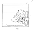
- Fig. 1 is a schematic diagram illustrating an outline of the structure of a monochrome printer according to an embodiment of the present invention
- Fig. 2 is a front perspective view illustrating an intermediate hopper of the monochrome printer according to an embodiment of the present invention
- Fig. 3 is a rear side sectional view illustrating the intermediate hopper of the monochrome printer according to an embodiment of the present invention
- Fig. 4 is a sectional view illustrating the structure of gears provided on a transmission shaft in the intermediate hopper of the monochrome printer according to an embodiment of the present invention
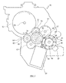
- Fig. 5 is a schematic diagram illustrating rotation directions of gears of the intermediate hopper of the monochrome printer according to an embodiment of the present invention when the drive motor rotates in a forward rotation direction;
- Fig. 6 is a schematic diagram illustrating torque transmission paths in the intermediate hopper of the monochrome printer according to an embodiment of the present invention when the drive motor rotates in the forward rotation direction;
- Fig. 7 is a schematic diagram illustrating the rotation directions of the gears in the intermediate hopper of the monochrome printer according to an embodiment of the present invention when the drive motor rotates in a backward rotation direction;
- Fig. 8 is a schematic diagram illustrating the torque transmission paths in the intermediate hopper of the monochrome printer according to an embodiment of the present invention when the drive motor rotates in the backward rotation direction;
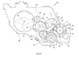
- Fig. 9 is a schematic diagram of an intermediate hopper according to another embodiment.
- Fig. 1 is a schematic diagram illustrating an outline of the structure of a monochrome printer according to an embodiment of the present invention.
- the monochrome printer 1 includes a box-shaped printer main body 2.
- a sheet feed cassette 3 is provided in a lower portion of the printer main body 2. Sheets of transfer paper (not shown) are loaded in the sheet feed cassette 3.
- a delivery tray 4 is provided at an upper end of the printer main body 2.
- a normally closed manual feed tray 5 is provided in a lower portion on one side surface (right side surface in Fig. 1 ) of the printer main body 2.
- An image forming unit 7 is located on one side (right side in Fig. 1 ) of the printer main body 2.
- a photoconductor drum 8 is rotatably provided in the image forming unit 7.
- a charger 10, a developing unit 11, a transfer unit 12, a cleaning device 13, and an eraser 14 are positioned around the photoconductor drum 8 in the order of transfer processes.
- a pair of agitating rollers 15 is located in a lower portion of the developing unit 11.
- a magnetic roller 16 is located above the pair of the agitating rollers 15, and a developing roller 17 is located above the magnetic roller 16.
- a toner transportation device 18 is located above the developing unit 11. The details of the toner transportation device 18 will be described hereinafter.
- a sheet feed unit 20 and a manual sheet feed unit 21 are located at an upstream end
- a fixing unit 22 is located in a downstream
- a sheet delivery port 23 is located at a downstream end.
- An inversion path 24 is formed at one end (right end in Fig. 1 ) of the printer main body 2.
- the power of the monochrome printer 1 When the power of the monochrome printer 1 is turned on, a variety of parameters are initialized, and initial settings such as a temperature setting of the fixing unit 22 are performed.
- initial settings such as a temperature setting of the fixing unit 22 are performed.
- a surface of the photoconductor drum 8 is initially charged by the charger 10. After that, the photoconductor drum 8 is exposed to laser light emitted from the exposure unit 6 corresponding to the image data, thereby forming an electrostatic latent image on the surface of the photoconductor drum 8. Next, the developing unit 11 develops the electrostatic latent image to a toner image with toner.
- a transfer sheet picked up by the sheet feed unit 20, or the manual sheet feed unit 21 from the sheet feed cassette 3 or the manual feed tray 5, is fed to the transfer unit 12 at a timing that is adjusted with respect to the timing of the above-described image forming operation.
- the transfer unit 12 transfers the toner image on the photoconductor drum 8 onto the transfer sheet.
- the transfer sheet, onto which the toner image has been transferred is fed through the transportation path 19 toward the downstream side, and enters the fixing unit 22.
- the fixing unit 22 fixes the toner image onto the transfer sheet.
- the transfer sheet, onto which the toner image has been fixed is delivered to the delivery tray 4 from the sheet delivery port 23. Toner and electrical charges remaining on the photoconductor drum 8 are removed by the cleaning device 13 and the eraser 14.
- Fig. 1 is a schematic diagram illustrating the outline of the structure of the monochrome printer according to an embodiment of the present invention.
- Fig. 2 is a front perspective view illustrating an intermediate hopper of the monochrome printer according to an embodiment of the present invention.
- Fig. 3 is a rear side sectional view illustrating the intermediate hopper of the monochrome printer according to an embodiment of the present invention seen from a rear side.
- Fig. 4 is a sectional view illustrating the structure of gears provided on the transmission shaft in the intermediate hopper of the monochrome printer according to an embodiment of the present invention.
- Fig. 1 is a schematic diagram illustrating the outline of the structure of the monochrome printer according to an embodiment of the present invention.
- Fig. 2 is a front perspective view illustrating an intermediate hopper of the monochrome printer according to an embodiment of the present invention.
- Fig. 3 is a rear side sectional view illustrating the intermediate hopper of the monochrome printer according to an embodiment of the present invention seen from a rear
- FIG. 5 is a schematic diagram illustrating rotation directions of gears of the intermediate hopper of the monochrome printer according to an embodiment of the present invention when a drive motor rotates in a forward rotation direction.
- Fig. 6 is a schematic diagram illustrating torque transmission paths in the intermediate hopper of the monochrome printer according to an embodiment of the present invention when the drive motor rotates in the forward rotation direction.
- Fig. 7 is a schematic diagram illustrating the rotation directions of the gears in the intermediate hopper of the monochrome printer according to an embodiment of the present invention when the drive motor rotates in a backward direction.
- Fig. 8 is a schematic diagram illustrating torque transmission paths in the intermediate hopper of the monochrome printer according to an embodiment of the present invention when the drive motor rotates in the backward direction.
- a front side in Fig. 1 is hereafter referred to as a front surface side of the toner transportation device 18.
- the toner transportation device 18 includes an intermediate hopper 26 serving as a toner case and a toner container 25 serving as another toner case.
- the toner container 25 is provided in an upper portion of the printer main body 2.
- the intermediate hopper 26 is located between the toner container 25 and the developing unit 11.
- the toner container 25 contains toner.
- the toner container 25 is removably mounted in a toner container mounting unit (not shown) provided in the printer main body 2.
- the toner container 25 is replaceable when the toner container 25 has run out of the toner.
- a pair of left and right agitating members 27 are rotatably positioned in a lower portion of the toner container 25.
- a transportation member 28 is rotatably provided at a position below the right agitating member 27 on the right hand side.
- the transportation member 28 and each of the agitating members 27 are connected to the container drive motor (not shown) provided in a container drive section (not shown).
- the container drive section is removably mounted to the toner container 25.
- the intermediate hopper 26 includes a main body 30 and a lid body 31.
- An upper side of the main body 30 is open.
- the lid body 31 covers the upper side of the main body 30.
- the main body 30 has a discharge port 33 (see Fig. 3 ) formed at a right end portion of a base wall 32 thereof.
- the interior of the main body 30 is connected to the interior of the developing unit 11 through the discharge port 33.
- the discharge port 33 is closed by a shutter 29 when the intermediate hopper 26 is not mounted to the developing unit 11. Mounting the intermediate hopper 26 to the developing unit 11 causes the shutter 29 to slide, thereby opening the discharge port 33.
- the above-described sliding shutter 29 is used.
- a rotating shutter may be used. In this situation, mounting the developing unit 11 in the printer main body 2 unlocks a lever. Then, by operation of the lever a user can cause the shutter to rotate, thereby opening the discharge port 33.
- a toner seal 34 is bonded to an area around the discharge port 33 on a lower surface of the base wall 32 of the main body 30.
- a transportation screw 35 which serves as a transportation unit, is rotatably mounted above the discharge port 33.
- the transportation screw 35 includes a rotation shaft 36, a spiral fin 37, and a transportation gear 38 (see Fig. 2 and so forth).
- the rotation shaft 36 is rotatably supported by the main body 30.
- the spiral fin 37 is concentrically provided in the outer periphery of the rotation shaft 36.
- the transportation gear 38 is provided at a front end of the rotation shaft 36.
- a transportation one-way clutch 39 is positioned between the transportation gear 38 and the rotation shaft 36 of the transportation screw 35.
- the transportation one-way clutch 39 can be formed using a one-way clutch structure such as a ratchet one-way clutch or a roller one-way clutch.
- the transportation one-way clutch 39 causes the rotation shaft 36, of the transportation screw 35, to rotate together with the transportation gear 38 when the transportation gear 38 rotates in one rotation direction of the transportation gear 38 (counterclockwise in front view in the present embodiment).
- the transportation one-way clutch 39 causes the transportation gear 38 to idle with respect to the rotation shaft 36 of the transportation screw 35 when the transportation gear 38 rotates in the other rotation direction of the transportation gear 38 (clockwise in front view in the present embodiment).
- a detection unit 40 is positioned in a front portion of the rotation shaft 36 of the transportation screw 35.
- the detection unit 40 includes a pulse plate 41 and a sensor 42.
- the pulse plate 41 is integrally formed with the transportation gear 38 at a position behind the transportation gear 38.
- the sensor 42 is secured to the main body 30 at a position below the pulse plate 41 on the right hand side.
- a light shielding portion 43 is provided in an outer diameter area of the pulse plate 41.
- the light shielding portion 43 has eight slits 44 equally spaced in a peripheral direction thereof.
- the sensor 42 is a photo interrupter sensor (a PI sensor) and includes a light emitter 45 and a light receiver 46.
- the light emitter 45 is positioned behind the light shielding portion 43 in a width direction of the pulse plate 41.
- the light receiver 46 is positioned in front of the light shielding portion 43 in the width direction of the pulse plate 41.
- the light emitter 45 and the light receiver 46 oppose each other and are located on one side and the other side of the light shielding portion 43.
- the number of rotations of the transportation screw 35 can be detected by detecting the number of rotations of the pulse plate 41.
- the detection result is used to estimate the remaining amount of the toner in the intermediate hopper 26.
- the sensor 42 detects 8 pulses during one rotation of the transportation screw 35 and the pulse plate 41.
- the sensor 42 is connected to a control unit (not shown), and can output a rotation number detection signal of the transportation screw 35 to the control unit.
- a first agitating paddle 47 (see Fig. 3 ), which serves as an agitating unit, is rotatably provided above the transportation screw 35 on the left hand side.
- the first agitating paddle 47 has a rotation shaft 48, which is rotatably supported by the main body 30.
- Agitating blades 50 are secured to an outer periphery of the rotation shaft 48.
- Each agitating blade 50 is formed of a flexible film such as, for example, a polyethylene terephthalate (PET) film or a polyester film.
- a first agitating gear 51 (see Fig. 2 and so forth) is located at a front end of the rotation shaft 48 of the first agitating paddle 47.
- a second agitating paddle 52 which serves as another agitating unit, is rotatably located on the left hand side of the first agitating paddle 47.
- the second agitating paddle 52 is located with a rotation shaft 53, which is rotatably supported by the main body 30.
- Agitating blades 54 are secured to an outer periphery of the rotation shaft 53.
- Each agitating blade 54 is formed of a flexible film such as, for example, a PET film or a polyester film.
- a second agitating gear 55 (see Fig. 2 and so forth) is located at a front end of the rotation shaft 53 of the second agitating paddle 52.
- a drive motor 56 which serves as a driving unit, is mounted in a front lower portion of the main body 30 so as to be inclined rightward from the lower to upper portions thereof.
- the drive motor 56 is a direct-current (DC) brush motor.
- any motor such as a DC brushless motor or a stepping motor instead of a DC brush motor may be used.
- the drive motor 56 is connected to the control unit (not shown) through a motor drive unit (not shown). A signal from the control unit causes a current to flow from the motor drive unit to the drive motor 56.
- the drive motor 56 includes a motor shaft 57 that is inclined rightward from the lower to upper portions thereof.
- a worm 58 is secured to the motor shaft 57.
- a right side of the worm 58 is engaged with the transportation gear 38.
- the motor shaft 57 is connected to the rotation shaft 36 of the transportation screw 35 through the worm 58, the transportation gear 38, and the transportation one-way clutch 39.
- the motor shaft 57 of the drive motor 56 is also connected to the rotation shaft 48 of the first agitating paddle 47 and the rotation shaft 53 of the second agitating paddle 52. These connections are described as follows.
- a transmission shaft 61 is positioned on the left hand side of the worm 58 located on the motor shaft 57.
- a first transmission gear 62 which is located at a front end portion of the transmission shaft 61, is engaged with the worm 58.
- a first one-way clutch 63 is located between the first transmission gear 62 and the transmission shaft 61.
- the first one-way clutch 63 can be formed using a one-way clutch structure such as a ratchet one-way clutch or a roller one-way clutch.
- the first one-way clutch 63 causes the transmission shaft 61 to rotate together with the first transmission gear 62 when the first transmission gear 62 rotates in one rotation direction of the first transmission gear 62 (clockwise in front view in the present embodiment).
- the first one-way clutch 63 causes the first transmission gear 62 to idle with respect to the transmission shaft 61 when the first transmission gear 62 rotates in the other rotation direction of the first transmission gear 62 (counterclockwise in front view in an embodiment).
- the first transmission gear 62 is engaged with a large diameter portion 65 of a first idle gear 64 located on the left hand side of the first transmission gear 62.
- a small diameter portion 66 of the first idle gear 64 is engaged with a second idle gear 67 located below the first idle gear 64 on the right hand side.
- the second idle gear 67 is engaged with a second transmission gear 68, which is located on the transmission shaft 61 behind the first transmission gear 62.
- a second one-way clutch 70 is positioned between the second transmission gear 68 and the transmission shaft 61.
- the second one-way clutch 70 can be formed using a one-way clutch structure such as a ratchet one-way clutch or a roller one-way clutch.
- the second one-way clutch 70 causes the transmission shaft 61 to rotate together with the second transmission gear 68 when the second transmission gear 68 rotates in one rotation direction of the second transmission gear 68 (clockwise in front view in an embodiment).
- the second one-way clutch 70 causes the second transmission gear 68 to idle with respect to the transmission shaft 61 when the second transmission gear 68 rotates in the other rotation direction of the second transmission gear 68 (counterclockwise in front view in an embodiment).
- a third transmission gear 71 which is rotatable together with the transmission shaft 61, is located behind the second transmission gear 68.
- the third transmission gear 71 is engaged with a large diameter portion 73 of a third idle gear 72 located above the third transmission gear 71.
- a right side of a small diameter portion 74 of the third idle gear 72 is engaged with the first agitating gear 51 located on the rotation shaft 48 of the first agitating paddle 47.
- the left side of the small diameter portion 74 of the third idle gear 72 is engaged with the second agitating gear 55 located on the rotation shaft 53 of the second agitating paddle 52.
- the motor shaft 57 of the drive motor 56 is connected to the rotation shaft 48 of the first agitating paddle 47 and the rotation shaft 53 of the second agitating paddle 52.
- the speed reduction ratio of the transportation screw 35 and the second agitating paddle 52 is set to 1/9. Accordingly, when the second agitating paddle 52 performs one rotation, the transportation screw 35 performs nine rotations. That is, while the second agitating paddle 52 performs one rotation, the sensor 42 of the detection unit 40 detects 72 pulses, calculated by multiplying 8 pulses (number of pulses generated during one rotation of the transportation screw 35) by 9.
- a toner amount detection sensor 75 is located in the main body 30 on the left hand side of the second agitating paddle 52.
- the toner amount detection sensor 75 comprises a piezoelectric sensor equipped with a piezoelectric element.
- the toner amount detection sensor 75 may be structured by a sensor different from the piezoelectric sensor such as, for example, an optical sensor or a magnetic permeability sensor.
- the toner amount detection sensor 75 is connected to the control unit (not shown) and turned on or off in accordance with the amount of toner in the intermediate hopper 26.
- An introduction port 76 is provided in the lid body 31 near a central area of the lid body 31 in a left-right direction. Toner transported from the toner container 25 is introduced into the intermediate hopper 26 through the introduction port 76.
- the control unit initially transmits a drive instruction signal (forward rotation direction) to the motor drive unit to cause the motor shaft 57 of the drive motor 56 to rotate in a forward rotation direction (counterclockwise rotation in the present embodiment).
- the rotation of the motor shaft 57 is transmitted to the transportation gear 38 through the worm 58, thereby rotating the transportation gear 38 counterclockwise.
- the transportation one-way clutch 39 causes the rotation shaft 36 of the transportation screw 35 to rotate together with the transportation gear 38, thereby rotating the transportation screw 35 counterclockwise.
- the toner in the intermediate hopper 26 is transported to the developing unit 11.
- the first transmission gear 62 rotates clockwise
- the first idle gear 64 rotates counterclockwise
- the second idle gear 67 rotates clockwise
- the second transmission gear 68 rotates counterclockwise.
- the second one-way clutch 70 causes the second transmission gear 68 to idle with respect to the transmission shaft 61. Accordingly, rotation is not transmitted from the second transmission gear 68 to the transmission shaft 61.
- the control unit initially transmits a drive instruction signal (backward rotation direction) to the motor drive unit to cause the motor shaft 57 of the drive motor 56 to rotate in a backward rotation direction (clockwise direction in the present embodiment).
- the rotation of the motor shaft 57 is transmitted to the transportation gear 38 through the worm 58, thereby rotating the transportation gear 38 clockwise.
- the transportation one-way clutch 39 causes the transportation gear 38 to idle with respect to the rotation shaft 36 of the transportation screw 35, thereby not transmitting rotation from the transportation gear 38 to the transportation screw 35. Accordingly, the transportation screw 35 does not rotate and toner is not supplied from the intermediate hopper 26 to the developing unit 11.
- the first transmission gear 62 rotates counterclockwise as described above
- the first idle gear 64 rotates clockwise
- the second idle gear 67 rotates counterclockwise
- the second transmission gear 68 rotates clockwise.
- the second one-way clutch 70 causes the transmission shaft 61 to rotate together with the second transmission gear 68. That is, the transmission shaft 61 and the third transmission gear 71 rotate clockwise.
- the large diameter portion 73 of the third idle gear 72 which is engaged with the third transmission gear 71, rotates counterclockwise, thereby rotating the first agitating gear 51 and the second agitating gear 55 clockwise. Accordingly, the first agitating paddle 47 and the second agitating paddle 52 are each rotated clockwise, thereby agitating the toner in the intermediate hopper 26.
- the above-described agitation of the toner is performed in order to make the surface of the toner in the intermediate hopper 26 level when the monochrome printer 1 is initialized wherein, for example, after the mode of the monochrome printer 1 has been changed from a sleep mode to a normal mode, after power is turned on, and the like.
- the agitation may be continued until the detection unit 40 detects the specified number of pulses. Assume that agitation is performed by rotating the second agitating paddle 52, for example, ten times.
- the agitation may be controlled so as to be continued until the accumulated number of times the rotation number detection signal has been output from the detection unit 40 to the control unit reaches 720 pulses, which is calculated by multiplying 72 pulses by 10.
- agitation of the toner without supplying the toner from the intermediate hopper 26 to the developing unit 11 is performed in order to make the surface of the toner in the intermediate hopper 26 level while the intermediate hopper 26 is being supplied the toner wherein, for example, the toner container 25 has been replaced.
- agitation of the toner may be continued, for example, until the supply of the toner from the toner container 25 to the intermediate hopper 26 is stopped due to switching of the state of a toner amount detection signal, which is outputted from the toner amount detection sensor 75 to the control unit, from low to high when the intermediate hopper 26 is completely filled with toner.
- the transportation screw 35 rotates.
- the transportation screw 35 stops.
- the monochrome printer 1 to operate in the following two cases: when it is desirable that the toner in the intermediate hopper 26 be agitated while the toner is supplied from the intermediate hopper 26 to the developing unit 11, and when it is desirable that the toner in the intermediate hopper 26 be agitated while toner is not supplied from the intermediate hopper 26 to the developing unit 11.
- the toner in the intermediate hopper 26 can be agitated. This can reduce compaction of the toner.
- the toner can always be smoothly transported. This allows the remaining amount of the toner in the intermediate hopper 26 to be quickly and correctly detected.
- the first and second agitating paddles 47 and 52 each rotate in the same direction as the direction in which the first and second agitating paddles 47 and 52 rotate when the drive motor 56 rotates in the forward rotation direction.
- toner can be reliably transported toward the transportation screw 35 using the first and second agitating paddles 47 and 52. This can improve efficiency of toner transportation.
- the first and second agitating paddles 47 and 52 rotate in the same direction when the drive motor 56 rotates in the forward rotation direction and when the drive motor 56 rotates in the backward rotation direction.
- leveling the surface of the toner in the intermediate hopper 26 using the first and second agitating paddles 47 and 52 can be increased.
- the intermediate hopper is supplied toner from the toner container.
- the intermediate hopper can be supplied toner from the toner container while toner in the intermediate hopper can be agitated without supplying toner to the developing unit.
- the agitating paddles include the first agitating paddle 47 and the second agitating paddle 52.
- the agitating paddles may include a third agitating paddle 80 in addition to the first and second agitating paddles 47 and 52 as illustrated in Fig. 9 .
- the following structure may be used. Specifically, the small diameter portion 74 of the third idle gear 72 is engaged with the large diameter portion 81 of the first agitating gear 51. A small diameter portion 82 of the first agitating gear 51 is engaged with a small diameter portion 84 of the second agitating gear 55 via a fourth idle gear 83.
- a large diameter portion 85 of the second agitating gear 55 is engaged with a third agitating gear 88 provided on a rotation shaft 87 of the third agitating paddle 80 via a fifth idle gear 86.
- the first to third agitating paddles 47, 52, and 80 can rotate in the same direction.
- the number and arrangement of the agitating paddles may be changed where appropriate in accordance with the size and shape of the intermediate hopper 26.
- the drive motor 56 is disposed so as to be inclined rightward from the lower to upper positions thereof. In yet another embodiment, as illustrated in Fig. 9 , the drive motor 56 may be positioned so as to be inclined rightward from the upper to lower portions thereof. In yet another embodiment, the drive motor 56 can assume a horizontal or vertical position. As described above, the position which the drive motor 56 assumes can be changed where appropriate in accordance with the size and shape of the intermediate hopper 26.
- a rotational direction of the drive motor 56 is a direction in which the motor shaft 57 of the drive motor 56 rotates in the forward rotation direction (counterclockwise rotation).
- the rotation direction of the drive motor 56 may be the direction in which the drive motor 56 rotates in the backward rotation direction (clockwise rotation).
- the rotation direction of the transportation gear 38 is the direction in which the transportation gear 38 rotates counterclockwise, as viewed from the front view, and the other rotation direction of the transportation gear 38 is the direction in which the transportation gear 38 rotates clockwise.
- the rotation direction of the transportation gear 38 may be a direction in which the transportation gear 38 rotates clockwise, when viewed from the front, and the other rotation direction of the transportation gear 38 may be the direction in which the transportation gear 38 rotates counterclockwise.
- each of the first and second agitating gears 51 and 55 is the direction in which each of the first and second agitating gears 51 and 55 rotates clockwise, when viewed from the front, and the other rotation direction of each of the first and second agitating gears 51 and 55 is the direction in which each of the first and second agitating gears 51 and 55 rotates counterclockwise.
- each of the first and second agitating gears 51 and 55 may be a direction in which each of the first and second agitating gears 51 and 55 rotates counterclockwise, when viewed from the front, and the other rotation direction of each of the first and second agitating gears 51 and 55 may be a direction in which each of the first and second agitating gears 51 and 55 rotates clockwise.
- each agitating unit is defined by a corresponding one of the agitating paddles
- the agitating unit may be defined by a screw-shaped member in yet another embodiment.
- the present disclosure is applied to the monochrome printer 1. In other embodiments, the present disclosure may be applied to color printers, copying machines, digital multi-function peripherals, facsimile machines, and other image forming apparatuses.
Landscapes
- Physics & Mathematics (AREA)
- General Physics & Mathematics (AREA)
- Dry Development In Electrophotography (AREA)
- Electrophotography Configuration And Component (AREA)
- Control Or Security For Electrophotography (AREA)
Abstract
Description
- The present invention relates to a toner containing case that contains toner, an image forming apparatus equipped with the toner containing case, and a method of driving a toner containing case.
- This application is based upon and claims the benefit of priority from the corresponding Japanese Patent application No.
2011-066040, filed March 24, 2011 - Today, in electrophotographic image forming apparatuses, toner is supplied from a developing unit to an electrostatic latent image formed on the surface of a photoconductor drum, or the like, to perform a developing process. Toner used in such a developing process is supplied to the developing unit from a toner case.
- For example, a toner case equipped with a toner container that contains toner and an intermediate hopper is known. The intermediate hopper is mounted between the toner container and the developing unit. The above-described intermediate hopper is typically provided with an agitating unit such as an agitating paddle and a transportation unit such as a transportation screw. The agitating unit agitates the toner and the transportation unit transports the toner. The intermediate hopper allows the toner transported from the toner container, to be transported to the developing unit using the transportation unit while the toner is agitated using the agitating unit. With the intermediate hopper having the above-described structure being located between the toner container and the developing unit, the toner can be supplied to the developing unit from the intermediate hopper even when the toner container runs out of toner. This allows the toner container to be replaced without a delay in the supply of toner to the developing unit.
- In the related art intermediate hopper having the above-described structure, in order to meet the demands for a reduction in the size of the apparatus and the like, the agitating unit and the transportation unit are rotated using a single driving unit (for example, a motor). That is, when the agitating unit is rotated by the driving unit, the transportation unit is always simultaneously rotated along with the agitating unit.
- In a toner case having the above-described structure, sometimes it is desirable that only an agitation of the toner contained in the intermediate hopper is performed. Such a situation occurs, for example, immediately after the mode of the image forming apparatus has been changed from a sleep mode to a normal mode, after the power has been turned on, after the toner container has been replaced, and the like. In addition, in order to quickly and correctly detect the remaining amount of the toner in the intermediate hopper, the toner contained in the intermediate hopper needs to be agitated even when toner is not being transported from the intermediate hopper to the developing unit. However, as described above, in the related art intermediate hopper, when the agitating unit is rotated, the transportation unit is always simultaneously rotated. Thus, operation of the intermediate hopper wherein the intermediate hopper agitates the toner without supplying the toner from the intermediate hopper to the developing unit cannot be performed.
- According to an embodiment of the present invention, a toner case is provided that includes a main body, that contains toner, a discharge port in the main body through which toner is discharged, an agitating unit rotatably provided in the main body that agitates the toner, a transportation unit rotatably provided in the main body that transports the toner toward the discharge port, and a driving unit that drives the transportation unit and the agitating unit. The driving unit is rotatable forward and backward. When the driving unit rotates in one rotation direction, the agitating unit and the transportation unit rotate. When the driving unit rotates in the other rotation direction, the transportation unit does not rotate and the agitating unit rotates in the same direction as the direction in which the agitating unit rotates when the driving unit rotates in the one rotation direction of the driving unit.
- According to another embodiment of the present invention, an image forming apparatus is provided that includes an apparatus main body, the above-described toner case, and a developing unit.
- According to yet another embodiment of the present invention, a method of driving a toner case is provided that drives a toner case. The toner case includes a main body that contains toner, a discharge port, provided in the main body, through which toner is discharged, an agitating unit rotatably provided in the main body that agitates the toner, a transportation unit rotatably provided in the main body that transports the toner toward the discharge port, and a driving unit that drives the transportation unit and the agitating unit. The method includes rotating the driving unit in one rotation direction of the driving unit so as to rotate the agitating unit and the transportation unit, and rotating the driving unit in the other rotation direction of the driving unit so as to rotate the agitating unit in the same direction as a direction in which the agitating unit rotates when the driving unit rotates in the one rotation direction of the driving unit and so as not to rotate the transportation unit.
- Additional features and advantages are described herein, and will be apparent from the following Detailed Description and the figures.
-
Fig. 1 is a schematic diagram illustrating an outline of the structure of a monochrome printer according to an embodiment of the present invention; -
Fig. 2 is a front perspective view illustrating an intermediate hopper of the monochrome printer according to an embodiment of the present invention; -
Fig. 3 is a rear side sectional view illustrating the intermediate hopper of the monochrome printer according to an embodiment of the present invention; -
Fig. 4 is a sectional view illustrating the structure of gears provided on a transmission shaft in the intermediate hopper of the monochrome printer according to an embodiment of the present invention; -
Fig. 5 is a schematic diagram illustrating rotation directions of gears of the intermediate hopper of the monochrome printer according to an embodiment of the present invention when the drive motor rotates in a forward rotation direction; -
Fig. 6 is a schematic diagram illustrating torque transmission paths in the intermediate hopper of the monochrome printer according to an embodiment of the present invention when the drive motor rotates in the forward rotation direction; -
Fig. 7 is a schematic diagram illustrating the rotation directions of the gears in the intermediate hopper of the monochrome printer according to an embodiment of the present invention when the drive motor rotates in a backward rotation direction; -
Fig. 8 is a schematic diagram illustrating the torque transmission paths in the intermediate hopper of the monochrome printer according to an embodiment of the present invention when the drive motor rotates in the backward rotation direction; and -
Fig. 9 is a schematic diagram of an intermediate hopper according to another embodiment. - The general structure of a monochrome printer 1 is initially described with reference to
Fig. 1. Fig. 1 is a schematic diagram illustrating an outline of the structure of a monochrome printer according to an embodiment of the present invention. - The monochrome printer 1 includes a box-shaped printer
main body 2. Asheet feed cassette 3 is provided in a lower portion of the printermain body 2. Sheets of transfer paper (not shown) are loaded in thesheet feed cassette 3. A delivery tray 4 is provided at an upper end of the printermain body 2. A normally closedmanual feed tray 5 is provided in a lower portion on one side surface (right side surface inFig. 1 ) of the printermain body 2. - An
exposure unit 6, which includes a laser scanning unit (LSU), is located in a lower central portion of the printermain body 2. An image forming unit 7 is located on one side (right side inFig. 1 ) of the printermain body 2. A photoconductor drum 8 is rotatably provided in the image forming unit 7. Acharger 10, a developing unit 11, a transfer unit 12, acleaning device 13, and aneraser 14 are positioned around the photoconductor drum 8 in the order of transfer processes. - A pair of agitating
rollers 15 is located in a lower portion of the developing unit 11. Amagnetic roller 16 is located above the pair of theagitating rollers 15, and a developing roller 17 is located above themagnetic roller 16. A toner transportation device 18 is located above the developing unit 11. The details of the toner transportation device 18 will be described hereinafter. - A
transportation path 19, through which a transfer sheet is transported, is formed on one side (right side inFig. 1 ) of the printermain body 2. Along thetransportation path 19, asheet feed unit 20 and a manualsheet feed unit 21 are located at an upstream end, afixing unit 22 is located in a downstream, and asheet delivery port 23 is located at a downstream end. An inversion path 24 is formed at one end (right end inFig. 1 ) of the printermain body 2. - Next, an image forming operation of the monochrome printer 1 having the above-described structure will be described.
- When the power of the monochrome printer 1 is turned on, a variety of parameters are initialized, and initial settings such as a temperature setting of the
fixing unit 22 are performed. When image data is inputted to the monochrome printer 1 from a computer or the like connected to the monochrome printer 1 and the monochrome printer 1 is instructed to start printing, the image forming operation is performed as follows. - A surface of the photoconductor drum 8 is initially charged by the
charger 10. After that, the photoconductor drum 8 is exposed to laser light emitted from theexposure unit 6 corresponding to the image data, thereby forming an electrostatic latent image on the surface of the photoconductor drum 8. Next, the developing unit 11 develops the electrostatic latent image to a toner image with toner. - A transfer sheet picked up by the
sheet feed unit 20, or the manualsheet feed unit 21 from thesheet feed cassette 3 or themanual feed tray 5, is fed to the transfer unit 12 at a timing that is adjusted with respect to the timing of the above-described image forming operation. The transfer unit 12 transfers the toner image on the photoconductor drum 8 onto the transfer sheet. The transfer sheet, onto which the toner image has been transferred, is fed through thetransportation path 19 toward the downstream side, and enters the fixingunit 22. The fixingunit 22 fixes the toner image onto the transfer sheet. The transfer sheet, onto which the toner image has been fixed, is delivered to the delivery tray 4 from thesheet delivery port 23. Toner and electrical charges remaining on the photoconductor drum 8 are removed by thecleaning device 13 and theeraser 14. - Next, the toner transportation device 18 will be described with reference to
Figs. 1 to 8 . As described above,Fig. 1 is a schematic diagram illustrating the outline of the structure of the monochrome printer according to an embodiment of the present invention.Fig. 2 is a front perspective view illustrating an intermediate hopper of the monochrome printer according to an embodiment of the present invention.Fig. 3 is a rear side sectional view illustrating the intermediate hopper of the monochrome printer according to an embodiment of the present invention seen from a rear side.Fig. 4 is a sectional view illustrating the structure of gears provided on the transmission shaft in the intermediate hopper of the monochrome printer according to an embodiment of the present invention.Fig. 5 is a schematic diagram illustrating rotation directions of gears of the intermediate hopper of the monochrome printer according to an embodiment of the present invention when a drive motor rotates in a forward rotation direction.Fig. 6 is a schematic diagram illustrating torque transmission paths in the intermediate hopper of the monochrome printer according to an embodiment of the present invention when the drive motor rotates in the forward rotation direction.Fig. 7 is a schematic diagram illustrating the rotation directions of the gears in the intermediate hopper of the monochrome printer according to an embodiment of the present invention when the drive motor rotates in a backward direction.Fig. 8 is a schematic diagram illustrating torque transmission paths in the intermediate hopper of the monochrome printer according to an embodiment of the present invention when the drive motor rotates in the backward direction. For convenience of explanation, a front side inFig. 1 is hereafter referred to as a front surface side of the toner transportation device 18. - As illustrated in
Fig. 1 , the toner transportation device 18 includes anintermediate hopper 26 serving as a toner case and a toner container 25 serving as another toner case. The toner container 25 is provided in an upper portion of the printermain body 2. Theintermediate hopper 26 is located between the toner container 25 and the developing unit 11. - The toner container 25 contains toner. The toner container 25 is removably mounted in a toner container mounting unit (not shown) provided in the printer
main body 2. The toner container 25 is replaceable when the toner container 25 has run out of the toner. - A pair of left and right agitating
members 27 are rotatably positioned in a lower portion of the toner container 25. Atransportation member 28 is rotatably provided at a position below theright agitating member 27 on the right hand side. Thetransportation member 28 and each of the agitatingmembers 27 are connected to the container drive motor (not shown) provided in a container drive section (not shown). The container drive section is removably mounted to the toner container 25. When the agitatingmembers 27 and thetransportation member 28 are rotated by the container drive motor, the toner in the toner container 25 is supplied to theintermediate hopper 26 while the toner is being agitated. - As illustrated in
Figs. 2 and3 , theintermediate hopper 26 includes amain body 30 and alid body 31. An upper side of themain body 30 is open. Thelid body 31 covers the upper side of themain body 30. - The
main body 30 has a discharge port 33 (seeFig. 3 ) formed at a right end portion of abase wall 32 thereof. The interior of themain body 30 is connected to the interior of the developing unit 11 through the discharge port 33. The discharge port 33 is closed by ashutter 29 when theintermediate hopper 26 is not mounted to the developing unit 11. Mounting theintermediate hopper 26 to the developing unit 11 causes theshutter 29 to slide, thereby opening the discharge port 33. In this embodiment, the above-described slidingshutter 29 is used. In another embodiment, a rotating shutter may be used. In this situation, mounting the developing unit 11 in the printermain body 2 unlocks a lever. Then, by operation of the lever a user can cause the shutter to rotate, thereby opening the discharge port 33. Atoner seal 34 is bonded to an area around the discharge port 33 on a lower surface of thebase wall 32 of themain body 30. - In the
main body 30, atransportation screw 35, which serves as a transportation unit, is rotatably mounted above the discharge port 33. Thetransportation screw 35 includes arotation shaft 36, aspiral fin 37, and a transportation gear 38 (seeFig. 2 and so forth). Therotation shaft 36 is rotatably supported by themain body 30. Thespiral fin 37 is concentrically provided in the outer periphery of therotation shaft 36. Thetransportation gear 38 is provided at a front end of therotation shaft 36. - A transportation one-way clutch 39 is positioned between the
transportation gear 38 and therotation shaft 36 of thetransportation screw 35. The transportation one-way clutch 39 can be formed using a one-way clutch structure such as a ratchet one-way clutch or a roller one-way clutch. The transportation one-way clutch 39 causes therotation shaft 36, of thetransportation screw 35, to rotate together with thetransportation gear 38 when thetransportation gear 38 rotates in one rotation direction of the transportation gear 38 (counterclockwise in front view in the present embodiment). The transportation one-way clutch 39 causes thetransportation gear 38 to idle with respect to therotation shaft 36 of thetransportation screw 35 when thetransportation gear 38 rotates in the other rotation direction of the transportation gear 38 (clockwise in front view in the present embodiment). - As most clearly illustrated in
Fig. 2 , adetection unit 40 is positioned in a front portion of therotation shaft 36 of thetransportation screw 35. Thedetection unit 40 includes apulse plate 41 and asensor 42. Thepulse plate 41 is integrally formed with thetransportation gear 38 at a position behind thetransportation gear 38. Thesensor 42 is secured to themain body 30 at a position below thepulse plate 41 on the right hand side. Alight shielding portion 43 is provided in an outer diameter area of thepulse plate 41. Thelight shielding portion 43 has eightslits 44 equally spaced in a peripheral direction thereof. - The
sensor 42 is a photo interrupter sensor (a PI sensor) and includes alight emitter 45 and alight receiver 46. Thelight emitter 45 is positioned behind thelight shielding portion 43 in a width direction of thepulse plate 41. Thelight receiver 46 is positioned in front of thelight shielding portion 43 in the width direction of thepulse plate 41. Thelight emitter 45 and thelight receiver 46 oppose each other and are located on one side and the other side of thelight shielding portion 43. When thepulse plate 41 rotates, a detection light path from thelight emitter 45 to thelight receiver 46 is continuously alternatingly formed and interrupted by theslits 44 and thelight shielding portion 43. By counting formation and interruption cycles, the number of rotations of thepulse plate 41 can be detected. Since thepulse plate 41 rotates together with therotation shaft 36 of thetransportation screw 35, the number of rotations of thetransportation screw 35 can be detected by detecting the number of rotations of thepulse plate 41. The detection result is used to estimate the remaining amount of the toner in theintermediate hopper 26. In an embodiment, since thepulse plate 41 has eightslits 44, thesensor 42 detects 8 pulses during one rotation of thetransportation screw 35 and thepulse plate 41. Thesensor 42 is connected to a control unit (not shown), and can output a rotation number detection signal of thetransportation screw 35 to the control unit. - In the
main body 30, a first agitating paddle 47 (seeFig. 3 ), which serves as an agitating unit, is rotatably provided above thetransportation screw 35 on the left hand side. The first agitatingpaddle 47 has arotation shaft 48, which is rotatably supported by themain body 30. Agitatingblades 50 are secured to an outer periphery of therotation shaft 48. Each agitatingblade 50 is formed of a flexible film such as, for example, a polyethylene terephthalate (PET) film or a polyester film. A first agitating gear 51 (seeFig. 2 and so forth) is located at a front end of therotation shaft 48 of the first agitatingpaddle 47. - A second agitating
paddle 52, which serves as another agitating unit, is rotatably located on the left hand side of the first agitatingpaddle 47. The second agitatingpaddle 52 is located with arotation shaft 53, which is rotatably supported by themain body 30. Agitatingblades 54 are secured to an outer periphery of therotation shaft 53. Each agitatingblade 54 is formed of a flexible film such as, for example, a PET film or a polyester film. A second agitating gear 55 (seeFig. 2 and so forth) is located at a front end of therotation shaft 53 of the second agitatingpaddle 52. - As most clearly illustrated in
Fig. 2 , adrive motor 56, which serves as a driving unit, is mounted in a front lower portion of themain body 30 so as to be inclined rightward from the lower to upper portions thereof. Thedrive motor 56 is a direct-current (DC) brush motor. In another embodiment, as thedrive motor 56, any motor such as a DC brushless motor or a stepping motor instead of a DC brush motor may be used. Thedrive motor 56 is connected to the control unit (not shown) through a motor drive unit (not shown). A signal from the control unit causes a current to flow from the motor drive unit to thedrive motor 56. - The
drive motor 56 includes amotor shaft 57 that is inclined rightward from the lower to upper portions thereof. Aworm 58 is secured to themotor shaft 57. A right side of theworm 58 is engaged with thetransportation gear 38. Thus, themotor shaft 57 is connected to therotation shaft 36 of thetransportation screw 35 through theworm 58, thetransportation gear 38, and the transportation one-way clutch 39. - The
motor shaft 57 of thedrive motor 56 is also connected to therotation shaft 48 of the first agitatingpaddle 47 and therotation shaft 53 of the second agitatingpaddle 52. These connections are described as follows. Atransmission shaft 61 is positioned on the left hand side of theworm 58 located on themotor shaft 57. Afirst transmission gear 62, which is located at a front end portion of thetransmission shaft 61, is engaged with theworm 58. - As illustrated in
Fig. 4 , a first one-way clutch 63 is located between thefirst transmission gear 62 and thetransmission shaft 61. The first one-way clutch 63 can be formed using a one-way clutch structure such as a ratchet one-way clutch or a roller one-way clutch. The first one-way clutch 63 causes thetransmission shaft 61 to rotate together with thefirst transmission gear 62 when thefirst transmission gear 62 rotates in one rotation direction of the first transmission gear 62 (clockwise in front view in the present embodiment). The first one-way clutch 63 causes thefirst transmission gear 62 to idle with respect to thetransmission shaft 61 when thefirst transmission gear 62 rotates in the other rotation direction of the first transmission gear 62 (counterclockwise in front view in an embodiment). - As illustrated in
Fig. 5 and so forth, thefirst transmission gear 62 is engaged with alarge diameter portion 65 of a firstidle gear 64 located on the left hand side of thefirst transmission gear 62. Asmall diameter portion 66 of the firstidle gear 64 is engaged with a secondidle gear 67 located below the firstidle gear 64 on the right hand side. The secondidle gear 67 is engaged with asecond transmission gear 68, which is located on thetransmission shaft 61 behind thefirst transmission gear 62. - As illustrated in
Fig. 4 , a second one-way clutch 70 is positioned between thesecond transmission gear 68 and thetransmission shaft 61. The second one-way clutch 70 can be formed using a one-way clutch structure such as a ratchet one-way clutch or a roller one-way clutch. The second one-way clutch 70 causes thetransmission shaft 61 to rotate together with thesecond transmission gear 68 when thesecond transmission gear 68 rotates in one rotation direction of the second transmission gear 68 (clockwise in front view in an embodiment). The second one-way clutch 70 causes thesecond transmission gear 68 to idle with respect to thetransmission shaft 61 when thesecond transmission gear 68 rotates in the other rotation direction of the second transmission gear 68 (counterclockwise in front view in an embodiment). - As illustrated in
Fig. 5 and so forth, athird transmission gear 71, which is rotatable together with thetransmission shaft 61, is located behind thesecond transmission gear 68. Thethird transmission gear 71 is engaged with alarge diameter portion 73 of a thirdidle gear 72 located above thethird transmission gear 71. A right side of asmall diameter portion 74 of the thirdidle gear 72 is engaged with the first agitatinggear 51 located on therotation shaft 48 of the first agitatingpaddle 47. The left side of thesmall diameter portion 74 of the thirdidle gear 72 is engaged with the second agitatinggear 55 located on therotation shaft 53 of the second agitatingpaddle 52. - With the above-described structure, the
motor shaft 57 of thedrive motor 56 is connected to therotation shaft 48 of the first agitatingpaddle 47 and therotation shaft 53 of the second agitatingpaddle 52. In an embodiment, the speed reduction ratio of thetransportation screw 35 and the second agitatingpaddle 52 is set to 1/9. Accordingly, when the second agitatingpaddle 52 performs one rotation, thetransportation screw 35 performs nine rotations. That is, while the second agitatingpaddle 52 performs one rotation, thesensor 42 of thedetection unit 40 detects 72 pulses, calculated by multiplying 8 pulses (number of pulses generated during one rotation of the transportation screw 35) by 9. - As illustrated in
Fig. 3 , a toneramount detection sensor 75 is located in themain body 30 on the left hand side of the second agitatingpaddle 52. In an embodiment, the toneramount detection sensor 75 comprises a piezoelectric sensor equipped with a piezoelectric element. In another embodiment, the toneramount detection sensor 75 may be structured by a sensor different from the piezoelectric sensor such as, for example, an optical sensor or a magnetic permeability sensor. The toneramount detection sensor 75 is connected to the control unit (not shown) and turned on or off in accordance with the amount of toner in theintermediate hopper 26. - The
lid body 31, which covers the upper side of themain body 30 as described above, is secured to themain body 30 using ultrasonic welding. Anintroduction port 76 is provided in thelid body 31 near a central area of thelid body 31 in a left-right direction. Toner transported from the toner container 25 is introduced into theintermediate hopper 26 through theintroduction port 76. - With the above-described structure, a case from which the toner is supplied from the
intermediate hopper 26 to the developing unit 11 while the toner in theintermediate hopper 26 is being agitated during, for example, a normal printing operation will be described with reference toFigs. 5 and6 . InFig. 6 , bold arrows indicate directions in which rotation of thedrive motor 56 is transmitted. - The control unit initially transmits a drive instruction signal (forward rotation direction) to the motor drive unit to cause the
motor shaft 57 of thedrive motor 56 to rotate in a forward rotation direction (counterclockwise rotation in the present embodiment). The rotation of themotor shaft 57 is transmitted to thetransportation gear 38 through theworm 58, thereby rotating thetransportation gear 38 counterclockwise. Due to this counterclockwise rotation of thetransportation gear 38, the transportation one-way clutch 39 causes therotation shaft 36 of thetransportation screw 35 to rotate together with thetransportation gear 38, thereby rotating thetransportation screw 35 counterclockwise. Thus, the toner in theintermediate hopper 26 is transported to the developing unit 11. - When the
motor shaft 57 of thedrive motor 56 rotates in the forward rotation direction as described above, rotation is transmitted to thefirst transmission gear 62 through theworm 58, thereby rotating thefirst transmission gear 62 clockwise. Due to this clockwise rotation of thefirst transmission gear 62, the first one-way clutch 63 causes thetransmission shaft 61 to rotate together with thefirst transmission gear 62. Thus, thetransmission shaft 61 and thethird transmission gear 71 rotate clockwise. Thelarge diameter portion 73 of the thirdidle gear 72, which is engaged with thethird transmission gear 71, rotates counterclockwise, thereby rotating clockwise the first agitatinggear 51 and the second agitatinggear 55, which are engaged with thesmall diameter portion 74 of the thirdidle gear 72. Accordingly, the first agitatingpaddle 47 and the second agitatingpaddle 52 are each also rotated clockwise. Thus, the toner in theintermediate hopper 26 is transported toward thetransportation screw 35 while the toner in theintermediate hopper 26 is agitated. - As described above, when the
first transmission gear 62 rotates clockwise, the firstidle gear 64 rotates counterclockwise, the secondidle gear 67 rotates clockwise, and thesecond transmission gear 68 rotates counterclockwise. When thesecond transmission gear 68 rotates counterclockwise as described above, the second one-way clutch 70 causes thesecond transmission gear 68 to idle with respect to thetransmission shaft 61. Accordingly, rotation is not transmitted from thesecond transmission gear 68 to thetransmission shaft 61. - Next, the situation wherein the toner in the
intermediate hopper 26 is agitated without supplying toner, for example, from theintermediate hopper 26 to the developing unit 11 will be described with reference toFigs. 7 and8 . InFig. 8 , bold arrows indicate the directions in which rotation of thedrive motor 56 is transmitted. - The control unit initially transmits a drive instruction signal (backward rotation direction) to the motor drive unit to cause the
motor shaft 57 of thedrive motor 56 to rotate in a backward rotation direction (clockwise direction in the present embodiment). The rotation of themotor shaft 57 is transmitted to thetransportation gear 38 through theworm 58, thereby rotating thetransportation gear 38 clockwise. When thetransportation gear 38 rotates clockwise as described above, the transportation one-way clutch 39 causes thetransportation gear 38 to idle with respect to therotation shaft 36 of thetransportation screw 35, thereby not transmitting rotation from thetransportation gear 38 to thetransportation screw 35. Accordingly, thetransportation screw 35 does not rotate and toner is not supplied from theintermediate hopper 26 to the developing unit 11. - When the
motor shaft 57 of thedrive motor 56 rotates in a backward rotation direction as described above, the rotation is transmitted to thefirst transmission gear 62 through theworm 58, thereby rotating thefirst transmission gear 62 counterclockwise. When thefirst transmission gear 62 rotates counterclockwise as described above, the first one-way clutch 63 causes thefirst transmission gear 62 to idle with respect to thetransmission shaft 61. Accordingly, rotation is not transmitted from thefirst transmission gear 62 to thetransmission shaft 61. - When the
first transmission gear 62 rotates counterclockwise as described above, the firstidle gear 64 rotates clockwise, the secondidle gear 67 rotates counterclockwise, and thesecond transmission gear 68 rotates clockwise. Due to this clockwise rotation of thesecond transmission gear 68, the second one-way clutch 70 causes thetransmission shaft 61 to rotate together with thesecond transmission gear 68. That is, thetransmission shaft 61 and thethird transmission gear 71 rotate clockwise. Thelarge diameter portion 73 of the thirdidle gear 72, which is engaged with thethird transmission gear 71, rotates counterclockwise, thereby rotating the first agitatinggear 51 and the second agitatinggear 55 clockwise. Accordingly, the first agitatingpaddle 47 and the second agitatingpaddle 52 are each rotated clockwise, thereby agitating the toner in theintermediate hopper 26. - The above-described agitation of the toner, without supplying the toner from the
intermediate hopper 26 to the developing unit 11, is performed in order to make the surface of the toner in theintermediate hopper 26 level when the monochrome printer 1 is initialized wherein, for example, after the mode of the monochrome printer 1 has been changed from a sleep mode to a normal mode, after power is turned on, and the like. In this situation, the agitation may be continued until thedetection unit 40 detects the specified number of pulses. Assume that agitation is performed by rotating the second agitatingpaddle 52, for example, ten times. In this situation, as described above, since the number of pulses corresponding to one rotation of the second agitatingpaddle 52 is 72, the agitation may be controlled so as to be continued until the accumulated number of times the rotation number detection signal has been output from thedetection unit 40 to the control unit reaches 720 pulses, which is calculated by multiplying 72 pulses by 10. - The above-described agitation of the toner without supplying the toner from the
intermediate hopper 26 to the developing unit 11 is performed in order to make the surface of the toner in theintermediate hopper 26 level while theintermediate hopper 26 is being supplied the toner wherein, for example, the toner container 25 has been replaced. In this situation, agitation of the toner may be continued, for example, until the supply of the toner from the toner container 25 to theintermediate hopper 26 is stopped due to switching of the state of a toner amount detection signal, which is outputted from the toneramount detection sensor 75 to the control unit, from low to high when theintermediate hopper 26 is completely filled with toner. - In an embodiment, as described above, when the
drive motor 56 rotates in the forward rotation direction, thetransportation screw 35 rotates. When thedrive motor 56 rotates in the backward rotation direction, thetransportation screw 35 stops. This allows the monochrome printer 1 to operate in the following two cases: when it is desirable that the toner in theintermediate hopper 26 be agitated while the toner is supplied from theintermediate hopper 26 to the developing unit 11, and when it is desirable that the toner in theintermediate hopper 26 be agitated while toner is not supplied from theintermediate hopper 26 to the developing unit 11. In addition, even when the toner is not transported from theintermediate hopper 26 to the developing unit 11, the toner in theintermediate hopper 26 can be agitated. This can reduce compaction of the toner. Thus, the toner can always be smoothly transported. This allows the remaining amount of the toner in theintermediate hopper 26 to be quickly and correctly detected. - When the
drive motor 56 rotates in the backward rotation direction, the first and second agitatingpaddles paddles drive motor 56 rotates in the forward rotation direction. With this structure, regardless of whether thedrive motor 56 rotates in the forward or backward rotation direction, toner can be reliably transported toward thetransportation screw 35 using the first and second agitatingpaddles paddles drive motor 56 rotates in the forward rotation direction and when thedrive motor 56 rotates in the backward rotation direction. Thus, leveling the surface of the toner in theintermediate hopper 26 using the first and second agitatingpaddles - In an embodiment, the intermediate hopper is supplied toner from the toner container. With the above-described structure being used, the intermediate hopper can be supplied toner from the toner container while toner in the intermediate hopper can be agitated without supplying toner to the developing unit.
- In an embodiment, as described above, the agitating paddles include the first agitating
paddle 47 and the second agitatingpaddle 52. In another embodiment, when theintermediate hopper 26 having a width greater than that of the previous embodiment is used, the agitating paddles may include a third agitatingpaddle 80 in addition to the first and second agitatingpaddles Fig. 9 . In this situation, the following structure may be used. Specifically, thesmall diameter portion 74 of the thirdidle gear 72 is engaged with the large diameter portion 81 of the first agitatinggear 51. Asmall diameter portion 82 of the first agitatinggear 51 is engaged with asmall diameter portion 84 of the second agitatinggear 55 via a fourthidle gear 83. A large diameter portion 85 of the second agitatinggear 55 is engaged with a third agitatinggear 88 provided on arotation shaft 87 of the third agitatingpaddle 80 via a fifthidle gear 86. With the above-described structure being used, the first to third agitatingpaddles intermediate hopper 26. - In an embodiment, the
drive motor 56 is disposed so as to be inclined rightward from the lower to upper positions thereof. In yet another embodiment, as illustrated inFig. 9 , thedrive motor 56 may be positioned so as to be inclined rightward from the upper to lower portions thereof. In yet another embodiment, thedrive motor 56 can assume a horizontal or vertical position. As described above, the position which thedrive motor 56 assumes can be changed where appropriate in accordance with the size and shape of theintermediate hopper 26. - In an embodiment, a rotational direction of the
drive motor 56 is a direction in which themotor shaft 57 of thedrive motor 56 rotates in the forward rotation direction (counterclockwise rotation). Alternatively, the rotation direction of thedrive motor 56 may be the direction in which thedrive motor 56 rotates in the backward rotation direction (clockwise rotation). - In an embodiment, the rotation direction of the
transportation gear 38 is the direction in which thetransportation gear 38 rotates counterclockwise, as viewed from the front view, and the other rotation direction of thetransportation gear 38 is the direction in which thetransportation gear 38 rotates clockwise. In yet another embodiment, the rotation direction of thetransportation gear 38 may be a direction in which thetransportation gear 38 rotates clockwise, when viewed from the front, and the other rotation direction of thetransportation gear 38 may be the direction in which thetransportation gear 38 rotates counterclockwise. - In an embodiment, the rotation direction of each of the first and second agitating gears 51 and 55 is the direction in which each of the first and second agitating gears 51 and 55 rotates clockwise, when viewed from the front, and the other rotation direction of each of the first and second agitating gears 51 and 55 is the direction in which each of the first and second agitating gears 51 and 55 rotates counterclockwise. In yet another embodiment, the rotation direction of each of the first and second agitating gears 51 and 55 may be a direction in which each of the first and second agitating gears 51 and 55 rotates counterclockwise, when viewed from the front, and the other rotation direction of each of the first and second agitating gears 51 and 55 may be a direction in which each of the first and second agitating gears 51 and 55 rotates clockwise.
- Although in an embodiment, each agitating unit is defined by a corresponding one of the agitating paddles, the agitating unit may be defined by a screw-shaped member in yet another embodiment.
- In an embodiment, the present disclosure is applied to the monochrome printer 1. In other embodiments, the present disclosure may be applied to color printers, copying machines, digital multi-function peripherals, facsimile machines, and other image forming apparatuses.
- It should be understood that various changes and modifications to the presently preferred embodiments described herein will be apparent to those skilled in the art. Such changes and modifications can be made without departing from the spirit and scope of the present subject matter and without diminishing its intended advantages. It is therefore intended that such changes and modifications be covered by the appended claims.
Claims (15)
- A toner case comprising:a main body that contains toner;a discharge port located in the main body through which toner is discharged;an agitating unit rotatably positioned in the main body that agitates the toner;a transportation unit rotatably positioned in the main body for transporting toner toward the discharge port; anda driving unit that drives the transportation unit and the agitating unit,the driving unit is rotatable forward and backward,when the driving unit rotates in one rotation direction of the driving unit, the agitating unit and the transportation unit rotate, andwhen the driving unit rotates in the other rotation direction of the driving unit, the transportation unit does not rotate and the agitating unit rotates in the same direction as a direction in which the agitating unit rotates when the driving unit rotates in the one rotation direction of the driving unit.
- The toner case according to Claim 1, comprising:a first transmission gear provided on a transmission shaft so as to allow the first transmission gear to rotate as the driving unit rotates;a first one-way clutch that causes the transmission shaft to rotate together with the first transmission gear when the first transmission gear rotates in one rotation direction of the first transmission gear, and causes the first transmission gear to idle with respect to the transmission shaft when the first transmission gear rotates in the other rotation direction of the first transmission gear;a first idle gear engaged with the first transmission gear;a second idle gear engaged with the first idle gear;a second transmission gear provided on the transmission shaft, the second transmission gear being engaged with the second idle gear;a second one-way clutch that causes the transmission shaft to rotate together with the second transmission gear when the second transmission gear rotates in one rotation direction of the second transmission gear, and causes the second transmission gear to idle with respect to the transmission shaft when the second transmission gear rotates in the other rotation direction of the second transmission gear; anda third transmission gear provided so as to be rotatable together with the transmission shaft, andthe agitating unit rotates as the third transmission gear rotates.
- The toner case according to Claim 2,
wherein a plurality of the agitating units are provided in the main body, and the plurality of agitating units rotate as the third transmission gear rotates. - The toner case according to Claim 1, 2 or 3 comprising:a transportation gear provided on a rotation shaft of the transportation unit; anda transportation one-way clutch that causes the rotation shaft of the transportation unit to rotate together with the transportation gear when the transportation gear rotates in one rotation direction of the transportation gear, and causes the transportation gear to idle with respect to the rotation shaft of the transportation unit when the transportation gear rotates in the other rotation direction of the transportation gear.
- The toner case according to Claim 1, 2, 3, 4 or 5, wherein the main body is supplied toner from another toner case.
- The toner case according to Claim 1,
wherein the driving unit includes a motor provided with a motor shaft,
the one rotation direction of the driving unit is a direction in which the driving unit rotates when the motor shaft rotates counterclockwise when viewed from the front, and
the other rotation direction of the driving unit is a direction in which the driving unit rotates when the motor shaft rotates clockwise when viewed from the front.;
or alternatively
the one rotation direction of the driving unit is a direction in which the driving unit rotates when the motor shaft rotates clockwise when viewed from the front, and
the other rotation direction of the driving unit is a direction in which the driving unit rotates when the motor shaft rotates counterclockwise when viewed from the front. - An image forming apparatus comprising:an apparatus main body;a toner case that includesa main body that contains toner,a discharge port located in the main body through which toner is discharged,an agitating unit rotatably positioned in the main body that agitates the toner,a transportation unit rotatably positioned in the main body for transporting toner toward the discharge port, anda driving unit that drives the transportation unit and the agitating unit; anda developing unit to which the toner is supplied through the discharge port of the toner case,the driving unit is rotatable forward and backward,when the driving unit rotates in one rotation direction of the driving unit, the agitating unit and the transportation unit rotate,wherein, when the driving unit rotates in the other rotation direction of the driving unit, the transportation unit does not rotate and the agitating unit rotates in the same direction as a direction in which the agitating unit rotates when the driving unit rotates in the one rotation direction of the driving unit.
- The image forming apparatus according to Claim 7,
wherein the toner case further includes
a first transmission gear provided on a transmission shaft so as to allow the first transmission gear to rotate as the driving unit rotates,
a first one-way clutch that causes the transmission shaft to rotate together with the first transmission gear when the first transmission gear rotates in one rotation direction of the first transmission gear, and causes the first transmission gear to idle with respect to the transmission shaft when the first transmission gear rotates in the other rotation direction of the first transmission gear,
a first idle gear engaged with the first transmission gear,
a second idle gear engaged with the first idle gear,
a second transmission gear provided on the transmission shaft, the second transmission gear being engaged with the second idle gear,
a second one-way clutch that causes the transmission shaft to rotate together with the second transmission gear when the second transmission gear rotates in one rotation direction of the second transmission gear, and causes the second transmission gear to idle with respect to the transmission shaft when the second transmission gear rotates in the other rotation direction of the second transmission gear,
a third transmission gear provided so as to be rotatable together with the transmission shaft, and
the agitating unit rotates as the third transmission gear rotates. - The image forming apparatus according to Claim 8,
wherein a plurality of the agitating units are provided in the main body, and the plurality of agitating units rotate as the third transmission gear rotates. - The image forming apparatus according to Claim 7, 8 or 9,
wherein the toner case further includes
a transportation gear provided on a rotation shaft of the transportation unit, and
a transportation one-way clutch that causes the rotation shaft of the transportation unit to rotate together with the transportation gear when the transportation gear rotates in one rotation direction of the transportation gear, and causes the transportation gear to idle with respect to the rotation shaft of the transportation unit when the transportation gear rotates in the other rotation direction of the transportation gear. - The image forming apparatus according to Claim 7, 8, 9 or 10, wherein the main body is supplied toner from another toner case.
- The image forming apparatus according to Claim 11,
wherein the other toner case includes a toner container removably mounted in the apparatus main body, and
the toner case includes an intermediate hopper mounted between the toner container and the developing unit.
preferably
wherein the driving unit rotates in the other rotation direction of the driving unit when the image forming apparatus is initialized. - The image forming apparatus according to Claim 12,
wherein, immediately after the toner container is mounted, the driving unit continues to rotate in the other rotation direction of the driving unit until the intermediate hopper is completely filled up with the toner. - The image forming apparatus according to Claim 7,
wherein the driving unit includes a motor provided with a motor shaft,
the one rotation direction of the driving unit is a direction in which the driving unit rotates when the motor shaft rotates counterclockwise when viewed from the front, and
the other rotation direction of the driving unit is a direction in which the driving unit rotates when the motor shaft rotates clockwise when viewed from the front;
or alternatively,
the one rotation direction of the driving unit is a direction in which the driving unit rotates when the motor shaft rotates clockwise when viewed from the front, and
the other rotation direction of the driving unit is a direction in which the driving unit rotates when the motor shaft rotates counterclockwise when viewed from the front. - A method of driving a toner case that includes a main body that contains toner, a discharge port located in the main body through which toner is discharged, an agitating unit rotatably positioned in the main body for agitating the toner, a transportation unit rotatably positioned in the main body for transporting the toner toward the discharge port, and a driving unit that drives the transportation unit and the agitating unit, the method comprising:rotating the driving unit in one rotation direction of the driving unit so as to rotate the agitating unit and the transportation unit; androtating the driving unit in the other rotation direction of the driving unit so as to rotate the agitating unit in the same direction as a direction in which the agitating unit rotates when the driving unit rotates in the one rotation direction of the driving unit and so as not to rotate the transportation unit.
Applications Claiming Priority (1)
| Application Number | Priority Date | Filing Date | Title |
|---|---|---|---|
| JP2011066040A JP5452532B2 (en) | 2011-03-24 | 2011-03-24 | Toner storage container and image forming apparatus |
Publications (2)
| Publication Number | Publication Date |
|---|---|
| EP2503399A1 true EP2503399A1 (en) | 2012-09-26 |
| EP2503399B1 EP2503399B1 (en) | 2019-04-24 |
Family
ID=45939172
Family Applications (1)
| Application Number | Title | Priority Date | Filing Date |
|---|---|---|---|
| EP12161203.0A Active EP2503399B1 (en) | 2011-03-24 | 2012-03-26 | Toner case |
Country Status (5)
| Country | Link |
|---|---|
| US (1) | US8768220B2 (en) |
| EP (1) | EP2503399B1 (en) |
| JP (1) | JP5452532B2 (en) |
| KR (1) | KR101376823B1 (en) |
| CN (1) | CN102692846A (en) |
Families Citing this family (7)
| Publication number | Priority date | Publication date | Assignee | Title |
|---|---|---|---|---|
| JP2014199395A (en) * | 2013-03-11 | 2014-10-23 | 株式会社リコー | Powder supply device and image forming apparatus |
| JP5856596B2 (en) * | 2013-09-24 | 2016-02-10 | 京セラドキュメントソリューションズ株式会社 | Toner container and image forming apparatus having the same |
| JP6127885B2 (en) * | 2013-10-03 | 2017-05-17 | 富士ゼロックス株式会社 | Image forming apparatus |
| JP6106584B2 (en) * | 2013-12-26 | 2017-04-05 | 京セラドキュメントソリューションズ株式会社 | Toner replenishment mechanism, image forming apparatus, and method for controlling toner replenishment |
| JP6610239B2 (en) * | 2015-12-22 | 2019-11-27 | コニカミノルタ株式会社 | Image forming apparatus |
| US11905848B2 (en) | 2019-06-05 | 2024-02-20 | Mitsubishi Heavy Industries, Ltd. | Turbine blade, manufacturing method for turbine blade, and gas turbine |
| JP2021056330A (en) * | 2019-09-30 | 2021-04-08 | ブラザー工業株式会社 | Developing unit |
Citations (4)
| Publication number | Priority date | Publication date | Assignee | Title |
|---|---|---|---|---|
| JPH11160985A (en) * | 1997-12-01 | 1999-06-18 | Canon Inc | Developer supply device |
| JP2000267419A (en) * | 1999-03-19 | 2000-09-29 | Canon Inc | Image forming device |
| US20060083553A1 (en) * | 2004-10-20 | 2006-04-20 | Canon Kabushiki Kaisha | Developer replenishment apparatus |
| JP2011066040A (en) | 2009-09-15 | 2011-03-31 | Casio Computer Co Ltd | Structure for mounting semiconductor device |
Family Cites Families (10)
| Publication number | Priority date | Publication date | Assignee | Title |
|---|---|---|---|---|
| JPS60145138A (en) | 1984-01-07 | 1985-07-31 | 田淵 和久 | sitting delivery table |
| JPS60145138U (en) * | 1984-03-08 | 1985-09-26 | 株式会社リコー | Original transport device |
| JP3451468B2 (en) * | 1995-10-03 | 2003-09-29 | 株式会社リコー | Toner supply device |
| JPH10254228A (en) * | 1997-03-11 | 1998-09-25 | Konica Corp | Image forming device |
| JP4366117B2 (en) * | 2003-05-21 | 2009-11-18 | キヤノン株式会社 | Toner supply device |
| US7447460B2 (en) * | 2005-08-31 | 2008-11-04 | Kyocera Mita Corporation | Color image forming device having an output toner transport member |
| KR20080075671A (en) * | 2007-02-13 | 2008-08-19 | 삼성전자주식회사 | An image forming apparatus, a developing unit provided therein, and a method of controlling the developing unit |
| JP2010256691A (en) * | 2009-04-27 | 2010-11-11 | Kyocera Mita Corp | Powder supply device and image forming apparatus |
| JP2010271601A (en) * | 2009-05-22 | 2010-12-02 | Oki Data Corp | Image forming apparatus |
| JP2010276955A (en) | 2009-05-29 | 2010-12-09 | Kyocera Mita Corp | Toner conveying device and image forming apparatus |
-
2011
- 2011-03-24 JP JP2011066040A patent/JP5452532B2/en active Active
-
2012
- 2012-03-12 KR KR1020120024949A patent/KR101376823B1/en active Active
- 2012-03-22 US US13/427,464 patent/US8768220B2/en active Active
- 2012-03-26 EP EP12161203.0A patent/EP2503399B1/en active Active
- 2012-03-26 CN CN2012100850609A patent/CN102692846A/en active Pending
Patent Citations (4)
| Publication number | Priority date | Publication date | Assignee | Title |
|---|---|---|---|---|
| JPH11160985A (en) * | 1997-12-01 | 1999-06-18 | Canon Inc | Developer supply device |
| JP2000267419A (en) * | 1999-03-19 | 2000-09-29 | Canon Inc | Image forming device |
| US20060083553A1 (en) * | 2004-10-20 | 2006-04-20 | Canon Kabushiki Kaisha | Developer replenishment apparatus |
| JP2011066040A (en) | 2009-09-15 | 2011-03-31 | Casio Computer Co Ltd | Structure for mounting semiconductor device |
Also Published As
| Publication number | Publication date |
|---|---|
| KR20120109306A (en) | 2012-10-08 |
| EP2503399B1 (en) | 2019-04-24 |
| JP5452532B2 (en) | 2014-03-26 |
| JP2012203100A (en) | 2012-10-22 |
| US20120243914A1 (en) | 2012-09-27 |
| KR101376823B1 (en) | 2014-03-20 |
| US8768220B2 (en) | 2014-07-01 |
| CN102692846A (en) | 2012-09-26 |
Similar Documents
| Publication | Publication Date | Title |
|---|---|---|
| US8676073B2 (en) | Toner transportation device, toner case, image forming apparatus, and method of controlling toner transportation device | |
| US8768220B2 (en) | Image forming apparatus having rotatable member drive mechanism in toner case | |
| CN103869658B (en) | Development device and image forming apparatus including the same | |
| EP0344072B2 (en) | System for drive control of a toner agitator in an image-forming apparatus and image-forming apparatus comprising said system | |
| US9244384B2 (en) | Developer container and image forming apparatus including the same | |
| US20120243887A1 (en) | Toner transportation device, toner case, image forming apparatus, and method of detecting remaining amount of toner | |
| JP4995299B2 (en) | Image forming apparatus and image forming method | |
| EP2626750B1 (en) | Developer case and image forming apparatus to which developer case is applied | |
| JP5588946B2 (en) | Toner supply device, toner container, and image forming apparatus | |
| US9098019B2 (en) | Toner replenishment mechanism with simple constitution, image forming apparatus with toner replenishment mechanism, and toner replenishment control method | |
| JP2010113030A (en) | Image forming apparatus | |
| US8725011B2 (en) | Toner transportation device, image forming apparatus, and method of detecting the amount of toner remaining | |
| JP5879282B2 (en) | Toner supply device and image forming apparatus | |
| JP4935277B2 (en) | Image forming apparatus | |
| JP5300002B2 (en) | Toner transport mechanism, developing device including the toner transport mechanism, and image forming apparatus | |
| JP2011064766A (en) | Image forming apparatus | |
| JP5612294B2 (en) | Image forming apparatus | |
| JP5719463B2 (en) | Toner container and image forming apparatus | |
| JP6601333B2 (en) | Image forming apparatus | |
| JP2011197255A (en) | Toner supply device and image forming apparatus with the same | |
| JP5755112B2 (en) | Image forming apparatus | |
| JP6610239B2 (en) | Image forming apparatus | |
| JP6658386B2 (en) | Image forming apparatus, toner container mounted on image forming apparatus | |
| JP2014191233A (en) | Developing device, image carrier unit, and image forming apparatus | |
| JP2010085520A (en) | Toner storage container |
Legal Events
| Date | Code | Title | Description |
|---|---|---|---|
| PUAI | Public reference made under article 153(3) epc to a published international application that has entered the european phase |
Free format text: ORIGINAL CODE: 0009012 |
|
| AK | Designated contracting states |
Kind code of ref document: A1 Designated state(s): AL AT BE BG CH CY CZ DE DK EE ES FI FR GB GR HR HU IE IS IT LI LT LU LV MC MK MT NL NO PL PT RO RS SE SI SK SM TR |
|
| AX | Request for extension of the european patent |
Extension state: BA ME |
|
| 17P | Request for examination filed |
Effective date: 20130326 |
|
| STAA | Information on the status of an ep patent application or granted ep patent |
Free format text: STATUS: EXAMINATION IS IN PROGRESS |
|
| 17Q | First examination report despatched |
Effective date: 20171110 |
|
| GRAP | Despatch of communication of intention to grant a patent |
Free format text: ORIGINAL CODE: EPIDOSNIGR1 |
|
| STAA | Information on the status of an ep patent application or granted ep patent |
Free format text: STATUS: GRANT OF PATENT IS INTENDED |
|
| INTG | Intention to grant announced |
Effective date: 20181106 |
|
| GRAS | Grant fee paid |
Free format text: ORIGINAL CODE: EPIDOSNIGR3 |
|
| GRAA | (expected) grant |
Free format text: ORIGINAL CODE: 0009210 |
|
| STAA | Information on the status of an ep patent application or granted ep patent |
Free format text: STATUS: THE PATENT HAS BEEN GRANTED |
|
| RAP1 | Party data changed (applicant data changed or rights of an application transferred) |
Owner name: KYOCERA DOCUMENT SOLUTIONS INC. |
|
| AK | Designated contracting states |
Kind code of ref document: B1 Designated state(s): AL AT BE BG CH CY CZ DE DK EE ES FI FR GB GR HR HU IE IS IT LI LT LU LV MC MK MT NL NO PL PT RO RS SE SI SK SM TR |
|
| REG | Reference to a national code |
Ref country code: GB Ref legal event code: FG4D |
|
| REG | Reference to a national code |
Ref country code: CH Ref legal event code: EP |
|
| REG | Reference to a national code |
Ref country code: AT Ref legal event code: REF Ref document number: 1124839 Country of ref document: AT Kind code of ref document: T Effective date: 20190515 Ref country code: IE Ref legal event code: FG4D |
|
| REG | Reference to a national code |
Ref country code: DE Ref legal event code: R096 Ref document number: 602012059262 Country of ref document: DE |
|
| REG | Reference to a national code |
Ref country code: NL Ref legal event code: MP Effective date: 20190424 |
|
| REG | Reference to a national code |
Ref country code: LT Ref legal event code: MG4D |
|
| PG25 | Lapsed in a contracting state [announced via postgrant information from national office to epo] |
Ref country code: NL Free format text: LAPSE BECAUSE OF FAILURE TO SUBMIT A TRANSLATION OF THE DESCRIPTION OR TO PAY THE FEE WITHIN THE PRESCRIBED TIME-LIMIT Effective date: 20190424 |
|
| PG25 | Lapsed in a contracting state [announced via postgrant information from national office to epo] |
Ref country code: HR Free format text: LAPSE BECAUSE OF FAILURE TO SUBMIT A TRANSLATION OF THE DESCRIPTION OR TO PAY THE FEE WITHIN THE PRESCRIBED TIME-LIMIT Effective date: 20190424 Ref country code: SE Free format text: LAPSE BECAUSE OF FAILURE TO SUBMIT A TRANSLATION OF THE DESCRIPTION OR TO PAY THE FEE WITHIN THE PRESCRIBED TIME-LIMIT Effective date: 20190424 Ref country code: LT Free format text: LAPSE BECAUSE OF FAILURE TO SUBMIT A TRANSLATION OF THE DESCRIPTION OR TO PAY THE FEE WITHIN THE PRESCRIBED TIME-LIMIT Effective date: 20190424 Ref country code: ES Free format text: LAPSE BECAUSE OF FAILURE TO SUBMIT A TRANSLATION OF THE DESCRIPTION OR TO PAY THE FEE WITHIN THE PRESCRIBED TIME-LIMIT Effective date: 20190424 Ref country code: NO Free format text: LAPSE BECAUSE OF FAILURE TO SUBMIT A TRANSLATION OF THE DESCRIPTION OR TO PAY THE FEE WITHIN THE PRESCRIBED TIME-LIMIT Effective date: 20190724 Ref country code: FI Free format text: LAPSE BECAUSE OF FAILURE TO SUBMIT A TRANSLATION OF THE DESCRIPTION OR TO PAY THE FEE WITHIN THE PRESCRIBED TIME-LIMIT Effective date: 20190424 Ref country code: PT Free format text: LAPSE BECAUSE OF FAILURE TO SUBMIT A TRANSLATION OF THE DESCRIPTION OR TO PAY THE FEE WITHIN THE PRESCRIBED TIME-LIMIT Effective date: 20190824 Ref country code: AL Free format text: LAPSE BECAUSE OF FAILURE TO SUBMIT A TRANSLATION OF THE DESCRIPTION OR TO PAY THE FEE WITHIN THE PRESCRIBED TIME-LIMIT Effective date: 20190424 |
|
| PG25 | Lapsed in a contracting state [announced via postgrant information from national office to epo] |
Ref country code: GR Free format text: LAPSE BECAUSE OF FAILURE TO SUBMIT A TRANSLATION OF THE DESCRIPTION OR TO PAY THE FEE WITHIN THE PRESCRIBED TIME-LIMIT Effective date: 20190725 Ref country code: BG Free format text: LAPSE BECAUSE OF FAILURE TO SUBMIT A TRANSLATION OF THE DESCRIPTION OR TO PAY THE FEE WITHIN THE PRESCRIBED TIME-LIMIT Effective date: 20190724 Ref country code: RS Free format text: LAPSE BECAUSE OF FAILURE TO SUBMIT A TRANSLATION OF THE DESCRIPTION OR TO PAY THE FEE WITHIN THE PRESCRIBED TIME-LIMIT Effective date: 20190424 Ref country code: PL Free format text: LAPSE BECAUSE OF FAILURE TO SUBMIT A TRANSLATION OF THE DESCRIPTION OR TO PAY THE FEE WITHIN THE PRESCRIBED TIME-LIMIT Effective date: 20190424 Ref country code: LV Free format text: LAPSE BECAUSE OF FAILURE TO SUBMIT A TRANSLATION OF THE DESCRIPTION OR TO PAY THE FEE WITHIN THE PRESCRIBED TIME-LIMIT Effective date: 20190424 |
|
| REG | Reference to a national code |
Ref country code: AT Ref legal event code: MK05 Ref document number: 1124839 Country of ref document: AT Kind code of ref document: T Effective date: 20190424 |
|
| PG25 | Lapsed in a contracting state [announced via postgrant information from national office to epo] |
Ref country code: IS Free format text: LAPSE BECAUSE OF FAILURE TO SUBMIT A TRANSLATION OF THE DESCRIPTION OR TO PAY THE FEE WITHIN THE PRESCRIBED TIME-LIMIT Effective date: 20190824 |
|
| REG | Reference to a national code |
Ref country code: DE Ref legal event code: R097 Ref document number: 602012059262 Country of ref document: DE |
|
| PG25 | Lapsed in a contracting state [announced via postgrant information from national office to epo] |
Ref country code: DK Free format text: LAPSE BECAUSE OF FAILURE TO SUBMIT A TRANSLATION OF THE DESCRIPTION OR TO PAY THE FEE WITHIN THE PRESCRIBED TIME-LIMIT Effective date: 20190424 Ref country code: SK Free format text: LAPSE BECAUSE OF FAILURE TO SUBMIT A TRANSLATION OF THE DESCRIPTION OR TO PAY THE FEE WITHIN THE PRESCRIBED TIME-LIMIT Effective date: 20190424 Ref country code: CZ Free format text: LAPSE BECAUSE OF FAILURE TO SUBMIT A TRANSLATION OF THE DESCRIPTION OR TO PAY THE FEE WITHIN THE PRESCRIBED TIME-LIMIT Effective date: 20190424 Ref country code: RO Free format text: LAPSE BECAUSE OF FAILURE TO SUBMIT A TRANSLATION OF THE DESCRIPTION OR TO PAY THE FEE WITHIN THE PRESCRIBED TIME-LIMIT Effective date: 20190424 Ref country code: AT Free format text: LAPSE BECAUSE OF FAILURE TO SUBMIT A TRANSLATION OF THE DESCRIPTION OR TO PAY THE FEE WITHIN THE PRESCRIBED TIME-LIMIT Effective date: 20190424 Ref country code: EE Free format text: LAPSE BECAUSE OF FAILURE TO SUBMIT A TRANSLATION OF THE DESCRIPTION OR TO PAY THE FEE WITHIN THE PRESCRIBED TIME-LIMIT Effective date: 20190424 |
|
| PG25 | Lapsed in a contracting state [announced via postgrant information from national office to epo] |
Ref country code: SM Free format text: LAPSE BECAUSE OF FAILURE TO SUBMIT A TRANSLATION OF THE DESCRIPTION OR TO PAY THE FEE WITHIN THE PRESCRIBED TIME-LIMIT Effective date: 20190424 Ref country code: IT Free format text: LAPSE BECAUSE OF FAILURE TO SUBMIT A TRANSLATION OF THE DESCRIPTION OR TO PAY THE FEE WITHIN THE PRESCRIBED TIME-LIMIT Effective date: 20190424 |
|
| PLBE | No opposition filed within time limit |
Free format text: ORIGINAL CODE: 0009261 |
|
| STAA | Information on the status of an ep patent application or granted ep patent |
Free format text: STATUS: NO OPPOSITION FILED WITHIN TIME LIMIT |
|
| PG25 | Lapsed in a contracting state [announced via postgrant information from national office to epo] |
Ref country code: TR Free format text: LAPSE BECAUSE OF FAILURE TO SUBMIT A TRANSLATION OF THE DESCRIPTION OR TO PAY THE FEE WITHIN THE PRESCRIBED TIME-LIMIT Effective date: 20190424 |
|
| 26N | No opposition filed |
Effective date: 20200127 |
|
| PG25 | Lapsed in a contracting state [announced via postgrant information from national office to epo] |
Ref country code: SI Free format text: LAPSE BECAUSE OF FAILURE TO SUBMIT A TRANSLATION OF THE DESCRIPTION OR TO PAY THE FEE WITHIN THE PRESCRIBED TIME-LIMIT Effective date: 20190424 |
|
| PG25 | Lapsed in a contracting state [announced via postgrant information from national office to epo] |
Ref country code: MC Free format text: LAPSE BECAUSE OF FAILURE TO SUBMIT A TRANSLATION OF THE DESCRIPTION OR TO PAY THE FEE WITHIN THE PRESCRIBED TIME-LIMIT Effective date: 20190424 |
|
| REG | Reference to a national code |
Ref country code: CH Ref legal event code: PL |
|
| REG | Reference to a national code |
Ref country code: BE Ref legal event code: MM Effective date: 20200331 |
|
| PG25 | Lapsed in a contracting state [announced via postgrant information from national office to epo] |
Ref country code: LU Free format text: LAPSE BECAUSE OF NON-PAYMENT OF DUE FEES Effective date: 20200326 |
|
| PG25 | Lapsed in a contracting state [announced via postgrant information from national office to epo] |
Ref country code: IE Free format text: LAPSE BECAUSE OF NON-PAYMENT OF DUE FEES Effective date: 20200326 Ref country code: CH Free format text: LAPSE BECAUSE OF NON-PAYMENT OF DUE FEES Effective date: 20200331 Ref country code: LI Free format text: LAPSE BECAUSE OF NON-PAYMENT OF DUE FEES Effective date: 20200331 |
|
| PG25 | Lapsed in a contracting state [announced via postgrant information from national office to epo] |
Ref country code: BE Free format text: LAPSE BECAUSE OF NON-PAYMENT OF DUE FEES Effective date: 20200331 |
|
| PG25 | Lapsed in a contracting state [announced via postgrant information from national office to epo] |
Ref country code: MT Free format text: LAPSE BECAUSE OF FAILURE TO SUBMIT A TRANSLATION OF THE DESCRIPTION OR TO PAY THE FEE WITHIN THE PRESCRIBED TIME-LIMIT Effective date: 20190424 Ref country code: CY Free format text: LAPSE BECAUSE OF FAILURE TO SUBMIT A TRANSLATION OF THE DESCRIPTION OR TO PAY THE FEE WITHIN THE PRESCRIBED TIME-LIMIT Effective date: 20190424 |
|
| PG25 | Lapsed in a contracting state [announced via postgrant information from national office to epo] |
Ref country code: MK Free format text: LAPSE BECAUSE OF FAILURE TO SUBMIT A TRANSLATION OF THE DESCRIPTION OR TO PAY THE FEE WITHIN THE PRESCRIBED TIME-LIMIT Effective date: 20190424 |
|
| P01 | Opt-out of the competence of the unified patent court (upc) registered |
Effective date: 20230420 |
|
| PGFP | Annual fee paid to national office [announced via postgrant information from national office to epo] |
Ref country code: GB Payment date: 20260220 Year of fee payment: 15 |
|
| PGFP | Annual fee paid to national office [announced via postgrant information from national office to epo] |
Ref country code: DE Payment date: 20260219 Year of fee payment: 15 |
|
| PGFP | Annual fee paid to national office [announced via postgrant information from national office to epo] |
Ref country code: FR Payment date: 20260219 Year of fee payment: 15 |