JP2011197255A - Toner supply device and image forming apparatus with the same - Google Patents

Toner supply device and image forming apparatus with the same Download PDF

Info

Publication number
JP2011197255A
JP2011197255A JP2010062600A JP2010062600A JP2011197255A JP 2011197255 A JP2011197255 A JP 2011197255A JP 2010062600 A JP2010062600 A JP 2010062600A JP 2010062600 A JP2010062600 A JP 2010062600A JP 2011197255 A JP2011197255 A JP 2011197255A
Authority
JP
Japan
Prior art keywords
toner
container
stirring
gear
transmission shaft
Prior art date
Legal status (The legal status is an assumption and is not a legal conclusion. Google has not performed a legal analysis and makes no representation as to the accuracy of the status listed.)
Pending
Application number
JP2010062600A
Other languages
Japanese (ja)
Inventor
Tatsuhiko Yoshii
達彦 吉井
Current Assignee (The listed assignees may be inaccurate. Google has not performed a legal analysis and makes no representation or warranty as to the accuracy of the list.)
Kyocera Document Solutions Inc
Original Assignee
Kyocera Mita Corp
Priority date (The priority date is an assumption and is not a legal conclusion. Google has not performed a legal analysis and makes no representation as to the accuracy of the date listed.)
Filing date
Publication date
Application filed by Kyocera Mita Corp filed Critical Kyocera Mita Corp
Priority to JP2010062600A priority Critical patent/JP2011197255A/en
Publication of JP2011197255A publication Critical patent/JP2011197255A/en
Pending legal-status Critical Current

Links

Images

Abstract

PROBLEM TO BE SOLVED: To provide a toner supply device that suppresses deterioration in toner and supplies high-fluidity toner to a developing device without causing enlargement of the device, and to provide an image forming apparatus including the same.SOLUTION: An intermediate hopper 120 includes a storage container 121 in which toner is stored, first and second stirring members 123 and 124 which rotate in the storage container 121 to stir the toner, and a conveying member 122 which rotates to supply the toner stirred by the first and the second stirring members 123 and 124 to the developing device 14. Furthermore, the intermediate hopper 120 includes a motor 150 which drives to rotate the conveying member 122, a joint 130 which is driven to rotate by a driving member on the developing device 14 side, and a third intermediate gear 135 which transmits torque to the first and the second stirring members 123 and 124 from the joint 130.

Description

本発明は、電子写真方式を利用した複写機、プリンタ、ファクシミリ、それらの複合機等の画像形成装置に備えられる現像器にトナーを供給するトナー補給装置及びそれを備えた画像形成装置に関するものである。   The present invention relates to a toner replenishing device that supplies toner to a developing device provided in an image forming apparatus such as a copying machine, a printer, a facsimile, or a composite machine using an electrophotographic system, and an image forming apparatus including the same. is there.

画像形成装置では、トナーを貯留するトナーコンテナから現像器にトナーを安定して供給する必要がある。近年、大量の印刷を迅速に行なうために、画像形成装置は高速化し、トナー消費量が増えている。トナーが消費され現像器内のトナーがなくなると、トナーが充填された新たなトナーコンテナに交換することになるが、高速の画像形成装置では、印字中にトナーコンテナを交換する必要が生じる場合もある。印字中にトナーコンテナを交換しても、画像形成を中断することがないようにしなくては、装置の操作性や印字効率が低下することになる。   In an image forming apparatus, it is necessary to stably supply toner to a developing device from a toner container that stores toner. In recent years, in order to perform a large amount of printing quickly, the image forming apparatus has been increased in speed and toner consumption has increased. When the toner is consumed and the toner in the developing device runs out, the toner container is replaced with a new toner container. However, in a high-speed image forming apparatus, it may be necessary to replace the toner container during printing. is there. Even if the toner container is replaced during printing, the operability of the apparatus and the printing efficiency are lowered unless the image formation is interrupted.

そこで、特許文献1では、トナーコンテナと現像器との間に中間ホッパーを設けている。トナーが無くなったトナーコンテナを中間ホッパーから取り外し、新たなトナーコンテナを中間ホッパーに装着して、トナーコンテナの交換中でも、中間ホッパーから現像器にトナーを供給することができるようにしている。   Therefore, in Patent Document 1, an intermediate hopper is provided between the toner container and the developing device. The toner container that has run out of toner is removed from the intermediate hopper, and a new toner container is mounted on the intermediate hopper so that the toner can be supplied from the intermediate hopper to the developing device even while the toner container is being replaced.

特開2005−114798号公報(段落[0042]〜[0047]、第3図)Japanese Patent Laying-Open No. 2005-114798 (paragraphs [0042] to [0047], FIG. 3)

通常、トナーは中間ホッパー内で撹拌部材によって撹拌され、トナーを収容する現像容器の容量に対応した量のトナーが中間ホッパーから現像容器に補給される。画像形成が繰り返され、再度、現像容器内のトナーがなくなると、前回と同様に、撹拌されたトナーが中間ホッパーから現像容器に所定量だけ補給される。この補給を行なう毎に中間ホッパー内でトナーの撹拌を繰り返すと、トナー間で激しく擦れ、トナー表面の外添剤がトナー内に埋没し、または、外添剤がトナー表面から剥がれてしまうことになる。このように劣化したトナーを用いて現像を行なうと、画像濃度の低下や画像欠損等の画像不良が発生するという問題点があった。   Usually, the toner is agitated by an agitating member in the intermediate hopper, and an amount of toner corresponding to the capacity of the developing container for containing the toner is supplied from the intermediate hopper to the developing container. When the image formation is repeated and the toner in the developing container runs out again, the agitated toner is supplied from the intermediate hopper to the developing container by a predetermined amount as in the previous case. If the stirring of the toner is repeated in the intermediate hopper every time this replenishment is performed, the toner is rubbed vigorously and the external additive on the toner surface is buried in the toner, or the external additive is peeled off from the toner surface. Become. When development is performed using such deteriorated toner, there is a problem in that image defects such as a decrease in image density and image loss occur.

そこで、コンテナから中間ホッパーへトナーを補給する時に撹拌部材を適度に回転させ、トナーを均することが必要である。そのこととともに、中間ホッパーから現像器へのトナー補給時に撹拌部材を適度に回転させ、トナーの流動性を良くすることも必要である。この両方の課題を満たすには、トナー撹拌用モータとトナー補給用モータとを中間ホッパー内に設けてれば良いが、これでは中間ホッパーが大型化し、また中間ホッパーのコストが高くなるという問題点があった。   Therefore, when the toner is replenished from the container to the intermediate hopper, it is necessary to rotate the stirring member appropriately to level the toner. At the same time, it is necessary to appropriately rotate the stirring member at the time of replenishing the toner from the intermediate hopper to the developing device to improve the toner fluidity. To satisfy both of these problems, a toner agitation motor and a toner replenishment motor may be provided in the intermediate hopper. However, this increases the size of the intermediate hopper and increases the cost of the intermediate hopper. was there.

本発明は、上記のような課題を解決するためになされたものであり、装置が大型化することなく、トナーの劣化を抑え、流動性の高いトナーを現像器に供給するトナー補給装置及びそれを備えた画像形成装置を提供することを目的とする。   The present invention has been made to solve the above-described problems, and a toner replenishing device that suppresses toner deterioration and supplies high-fluidity toner to a developing device without increasing the size of the device, and the same An object of the present invention is to provide an image forming apparatus including the above.

上記目的を達成するために本発明は、トナーを貯留する貯留容器と、前記貯留容器内で回転してトナーを撹拌する撹拌部材と、前記撹拌部材により撹拌されたトナーを現像器に供給するために回転する搬送部材と、前記搬送部材を回転駆動させるモータと、現像器側の駆動部材によって回転駆動させられる連結部材と、前記連結部材から前記撹拌部材に回転駆動力を伝達する少なくとも一つの中間ギアとを備えることを特徴としている。   To achieve the above object, the present invention provides a storage container for storing toner, a stirring member that rotates in the storage container and stirs the toner, and supplies the toner stirred by the stirring member to the developing device. A conveying member that rotates in a rotating manner, a motor that rotationally drives the conveying member, a connecting member that is rotated by a driving member on the developing device side, and at least one intermediate that transmits a rotational driving force from the connecting member to the stirring member It is characterized by having a gear.

この構成によれば、撹拌部材と搬送部材は互いに独立して回転し、撹拌部材は現像器側の駆動部材によって回転駆動しトナーを撹拌する。   According to this configuration, the stirring member and the conveying member rotate independently of each other, and the stirring member is rotationally driven by the driving member on the developing device side to stir the toner.

また、請求項2に記載の発明では、前記モータからの回転駆動力を前記搬送部材に伝達する伝達軸が設けられ、前記中間ギアの何れか一つの回転軸は前記伝達軸と同軸となるように配置され、前記伝達軸の周りで自由回転することを特徴としている。   According to a second aspect of the present invention, a transmission shaft for transmitting the rotational driving force from the motor to the transport member is provided, and any one of the intermediate gears is coaxial with the transmission shaft. And is free to rotate around the transmission shaft.

また、請求項3に記載の発明では、前記モータの駆動出力軸にはウオームが固定され、前記伝達軸には前記ウオームと噛み合うウオームホイルが設けられることを特徴としている。   According to a third aspect of the present invention, a worm is fixed to the drive output shaft of the motor, and a worm wheel that meshes with the worm is provided on the transmission shaft.

また、請求項4に記載の発明では、前記搬送部材は、前記貯留容器に回転自在に支持される軸部と、前記軸部の周りに形成される螺旋羽根とを有し、前記伝達軸は前記搬送部材の軸部と同軸で一体に設けられることを特徴としている。   In the invention according to claim 4, the conveying member has a shaft portion rotatably supported by the storage container, and a spiral blade formed around the shaft portion, and the transmission shaft is It is characterized by being provided coaxially and integrally with the shaft portion of the conveying member.

また、請求項5に記載の発明では、上記の構成のトナー補給装置が搭載された画像形成装置である。   According to a fifth aspect of the present invention, there is provided an image forming apparatus equipped with the toner replenishing device having the above configuration.

請求項1に記載の発明によれば、撹拌部材と搬送部材は互いに独立して回転駆動し、撹拌部材は現像器側の駆動部材によって回転しトナーを撹拌するので、現像器が作動するときにトナー撹拌が行なわれ、トナーの流動性は良くなる。また、トナー補給装置から現像器にトナーを補給する毎にトナー補給装置内のトナーを撹拌することがないので、過度な撹拌がなくなり、トナーの劣化が抑えられる。更に撹拌部材を回転駆動するモータ等の駆動部材を別途設ける必要がないのでトナー補給装置が小型になり、またトナー補給装置をコストダウンすることができる。   According to the first aspect of the present invention, the stirring member and the conveying member are driven to rotate independently of each other, and the stirring member is rotated by the driving member on the developing device side to stir the toner. The toner is agitated and the fluidity of the toner is improved. Further, since the toner in the toner replenishing device is not agitated every time the toner is replenished from the toner replenishing device to the developing device, excessive agitation is eliminated and toner deterioration is suppressed. Further, since it is not necessary to separately provide a driving member such as a motor for rotating the stirring member, the toner replenishing device can be downsized and the toner replenishing device can be reduced in cost.

また、請求項2に記載の発明によれば、伝達軸と少なくとも一つの中間ギアとの回転軸は同軸となるように配置され、中間ギアは伝達軸の周りで自由回転するので、ギア、伝達軸等の駆動機構が装置内に大きな容積を占有することがなく、装置が小型化する。   According to the second aspect of the present invention, the rotation shaft of the transmission shaft and the at least one intermediate gear is arranged to be coaxial, and the intermediate gear freely rotates around the transmission shaft. The drive mechanism such as the shaft does not occupy a large volume in the apparatus, and the apparatus is downsized.

また、請求項3に記載の発明によれば、搬送部材はウオームギアによって回転駆動されるので、装置内に大きな容積を占有することがなく、装置が小型化する。   According to the third aspect of the present invention, since the conveying member is rotationally driven by the worm gear, the apparatus does not occupy a large volume and the apparatus is downsized.

また、請求項4の発明によれば、伝達軸は搬送部材の軸部と同軸で一体に設けられるので、モータによる回転駆動力を搬送部材に確実に伝達することができ、トナー補給装置から現像器へのトナー供給量が安定する。   According to the invention of claim 4, since the transmission shaft is provided coaxially and integrally with the shaft portion of the conveying member, the rotational driving force by the motor can be reliably transmitted to the conveying member, and the toner replenishing device can develop the toner. The amount of toner supplied to the container is stabilized.

また、請求項5に記載の発明によれば、装置が大型化することなく、トナーの劣化を抑え、流動性の高いトナーを現像器に供給するトナー補給装置を備える画像形成装置にすることができる。   According to the fifth aspect of the present invention, an image forming apparatus including a toner replenishing device that suppresses toner deterioration and supplies high-fluidity toner to a developing device without increasing the size of the device. it can.

本発明の実施形態に係るトナー補給装置が搭載された画像形成装置の概略構成を示す図1 is a diagram illustrating a schematic configuration of an image forming apparatus equipped with a toner supply device according to an embodiment of the present invention. 本実施形態に係るトナー補給装置からトナーが補給される現像器の概略構成を示す側面断面図Side surface sectional view which shows schematic structure of the developing device with which toner is replenished from the toner replenishing device according to the present embodiment 本実施形態に係るトナー補給装置を示す側面断面図Side surface sectional view showing a toner replenishing device according to the present embodiment. 本実施形態に係るトナー補給装置を示す斜視図The perspective view which shows the toner replenishing apparatus which concerns on this embodiment. 本実施形態に係るトナー補給装置の駆動機構部を示す斜視図The perspective view which shows the drive mechanism part of the toner supply apparatus which concerns on this embodiment. 本実施形態に係るトナー補給装置の駆動機構部の要部を示す断面図Sectional drawing which shows the principal part of the drive mechanism part of the toner supply apparatus which concerns on this embodiment.

以下に本発明の実施形態について図面を参照して説明するが、本発明はこの実施形態に限定されない。また発明の用途やここで示す用語等はこれに限定されるものではない。   Embodiments of the present invention will be described below with reference to the drawings, but the present invention is not limited to these embodiments. Further, the use of the invention and the terms shown here are not limited thereto.

図1は、本発明の実施形態に係るトナー補給装置である中間ホッパーを搭載した画像形成装置の概略構成を示す図である。画像形成装置1は、その下部に配設された給紙部2と、この給紙部2の側方に配設された用紙搬送部3と、この用紙搬送部3の上方に配設された画像形成部4と、この画像形成部4よりも排出側に配設された定着部5と、画像形成部4及び定着部5の上方に配設された画像読取部6と、トナーコンテナ110及び中間ホッパー120とを備えている。   FIG. 1 is a diagram showing a schematic configuration of an image forming apparatus equipped with an intermediate hopper which is a toner replenishing device according to an embodiment of the present invention. The image forming apparatus 1 is provided with a sheet feeding unit 2 disposed in a lower portion thereof, a sheet conveying unit 3 disposed on a side of the sheet feeding unit 2, and an upper side of the sheet conveying unit 3. An image forming unit 4, a fixing unit 5 disposed on the discharge side of the image forming unit 4, an image reading unit 6 disposed above the image forming unit 4 and the fixing unit 5, a toner container 110, and And an intermediate hopper 120.

給紙部2は、用紙9を収容する複数の給紙カセット7を備えており、給紙ローラ8の回転動作により、複数の給紙カセット7のうち選択された給紙カセット7から用紙9を1枚ずつ確実に用紙搬送部3に送り出す。   The paper feed unit 2 includes a plurality of paper feed cassettes 7 for containing paper 9, and the paper 9 is fed from the selected paper feed cassette 7 among the plurality of paper feed cassettes 7 by the rotation of the paper feed roller 8. Each sheet is surely sent out to the sheet transport unit 3.

用紙搬送部3に送られた用紙9は、用紙搬送経路10を経由して画像形成部4に向けて搬送される。画像形成部4は、電子写真プロセスによって、用紙9にトナー像を形成するものであり、図1の矢印方向に回転可能に軸支された感光体11と、この感光体11の周囲にその回転方向に沿って、帯電部12、露光部13、現像器14、転写部15、クリーニング部16、及び除電部17を備えている。   The paper 9 sent to the paper transport unit 3 is transported toward the image forming unit 4 via the paper transport path 10. The image forming unit 4 forms a toner image on the paper 9 by an electrophotographic process. The image forming unit 4 is rotatably supported in the direction of the arrow in FIG. A charging unit 12, an exposure unit 13, a developing device 14, a transfer unit 15, a cleaning unit 16, and a charge eliminating unit 17 are provided along the direction.

帯電部12は、高電圧を印加される帯電ワイヤを備えており、この帯電ワイヤからのコロナ放電によって感光体11表面に所定電位を与えると、感光体11表面が一様に帯電させられる。そして、画像読取部6によって読み取られた原稿の画像データに基づく光が、露光部13により感光体11に照射されると、感光体11の表面電位が選択的に減衰され、感光体11表面に静電潜像が形成される。   The charging unit 12 includes a charging wire to which a high voltage is applied. When a predetermined potential is applied to the surface of the photoconductor 11 by corona discharge from the charging wire, the surface of the photoconductor 11 is uniformly charged. Then, when light based on the image data of the original read by the image reading unit 6 is irradiated to the photoconductor 11 by the exposure unit 13, the surface potential of the photoconductor 11 is selectively attenuated, and the surface of the photoconductor 11 is irradiated. An electrostatic latent image is formed.

次いで、現像器14が感光体11表面の静電潜像を現像し、感光体11表面にトナー像が形成される。このトナー像が転写部15によって感光体11と転写部15との間に供給された用紙9に転写される。   Next, the developing device 14 develops the electrostatic latent image on the surface of the photoconductor 11, and a toner image is formed on the surface of the photoconductor 11. This toner image is transferred by the transfer unit 15 to the paper 9 supplied between the photoconductor 11 and the transfer unit 15.

トナー像が転写された用紙9は、画像形成部4の用紙搬送方向の下流側に配置された定着部5に向けて搬送される。定着部5では、加熱部材18及び加圧ローラ19によって、用紙9が加熱加圧され、用紙9上にトナー像が溶融定着される。次いで、トナー像が定着された用紙9は、排出ローラ対20によって排出トレイ21上に排出される。   The sheet 9 on which the toner image has been transferred is conveyed toward the fixing unit 5 disposed on the downstream side of the image forming unit 4 in the sheet conveying direction. In the fixing unit 5, the sheet 9 is heated and pressed by the heating member 18 and the pressure roller 19, and the toner image is melted and fixed on the sheet 9. Next, the sheet 9 on which the toner image is fixed is discharged onto the discharge tray 21 by the discharge roller pair 20.

転写部15による転写後、感光体11表面に残留しているトナーは、クリーニング部16により除去され、また感光体11表面の残留電荷は除電部17により除去される。そして、感光体11は帯電部12によって再び帯電され、以下同様にして画像形成が行われる。   After the transfer by the transfer unit 15, the toner remaining on the surface of the photoconductor 11 is removed by the cleaning unit 16, and the residual charge on the surface of the photoconductor 11 is removed by the charge eliminating unit 17. Then, the photosensitive member 11 is charged again by the charging unit 12, and image formation is performed in the same manner.

画像形成が繰り返し行われると現像器14のトナーが消費される。現像器14にトナーを供給するために、現像器14の上方には、トナーコンテナ110及び中間ホッパー120が配設されている。トナーコンテナ110は未使用のトナーを貯留するものであり、中間ホッパー120は、トナーコンテナ110からトナーを受け取り、トナーを解して現像器14に供給する。   When image formation is repeated, the toner of the developing device 14 is consumed. In order to supply toner to the developing device 14, a toner container 110 and an intermediate hopper 120 are disposed above the developing device 14. The toner container 110 stores unused toner, and the intermediate hopper 120 receives the toner from the toner container 110, releases the toner, and supplies it to the developing device 14.

次に、現像器について図2に基づいて説明する。図2は画像形成装置1に用いられる現像器14の概略構成を示す断面側面図である。   Next, the developing device will be described with reference to FIG. FIG. 2 is a cross-sectional side view showing a schematic configuration of the developing device 14 used in the image forming apparatus 1.

現像器14は、一成分磁性トナーを収容する現像容器22と、このトナーを撹拌する撹拌スクリュー23、24と、現像ローラ27、及び規制部材28とを備えている。   The developing device 14 includes a developing container 22 that stores one-component magnetic toner, stirring screws 23 and 24 that stir the toner, a developing roller 27, and a regulating member 28.

撹拌スクリュー23、24は、現像容器22内に回転可能に配設され、トナーを撹拌、循環させて、現像ローラ27に供給する。   The agitating screws 23 and 24 are rotatably disposed in the developing container 22, and agitate and circulate the toner and supply the toner to the developing roller 27.

現像ローラ27は、固定磁石体25と現像スリーブ26とを備える。現像スリーブ26は、円筒状の非磁性材からなり、撹拌スクリュー24に隣接する位置で現像容器22に回転可能に支持される。固定磁石体25は、現像スリーブ26内に固設される永久磁石からなり、現像スリーブ26に向けて磁界を発生する。また、現像ローラ27は、現像容器22の開口から露出し、像担持体である感光体11に一定の間隔を隔てて対向している。この対向する領域は、現像スリーブ26上に担持されているトナーを感光体11に向けて供給するための現像領域Dとなっている。更に、現像スリーブ26には、トナーを感光体11に供給するために、直流に交流を重畳した現像バイアス29が印加される。   The developing roller 27 includes a fixed magnet body 25 and a developing sleeve 26. The developing sleeve 26 is made of a cylindrical nonmagnetic material and is rotatably supported by the developing container 22 at a position adjacent to the stirring screw 24. The fixed magnet body 25 is a permanent magnet fixed in the developing sleeve 26 and generates a magnetic field toward the developing sleeve 26. Further, the developing roller 27 is exposed from the opening of the developing container 22 and faces the photosensitive member 11 that is an image carrier at a predetermined interval. This facing area is a developing area D for supplying the toner carried on the developing sleeve 26 toward the photoreceptor 11. Further, a developing bias 29 in which alternating current is superimposed on direct current is applied to the developing sleeve 26 in order to supply toner to the photoreceptor 11.

規制部材28は、現像スリーブ26表面に担持されるトナーを所定の層厚に規制するものであり、現像スリーブ26の略上方で現像スリーブ26表面との間に所定間隔を隔てて、現像容器22に取り付けられる。   The regulating member 28 regulates the toner carried on the surface of the developing sleeve 26 to a predetermined layer thickness. The developing container 22 is spaced a predetermined distance from the surface of the developing sleeve 26 substantially above the developing sleeve 26. Attached to.

現像スリーブ26内の固定磁石体25の磁力により、撹拌スクリュー24から供給されたトナーが現像スリーブ26表面に担持される。担持されたトナーは、規制部材28により所定の層厚に規制され、現像スリーブ26の回転(図2の矢印方向の回転)により、現像領域Dに向けて搬送される。現像スリーブ26に現像バイアス29が印加されることにより、現像領域Dにおいて現像スリーブ26と感光体11との間に電位差が発生し、現像スリーブ26上のトナーは感光体11に供給され、感光体11上の静電潜像はトナー像に現像される。   The toner supplied from the stirring screw 24 is carried on the surface of the developing sleeve 26 by the magnetic force of the fixed magnet body 25 in the developing sleeve 26. The carried toner is regulated to a predetermined layer thickness by the regulating member 28 and is conveyed toward the developing region D by the rotation of the developing sleeve 26 (rotation in the direction of the arrow in FIG. 2). When a developing bias 29 is applied to the developing sleeve 26, a potential difference is generated between the developing sleeve 26 and the photoconductor 11 in the developing region D, and the toner on the developing sleeve 26 is supplied to the photoconductor 11 and the photoconductor. The electrostatic latent image on 11 is developed into a toner image.

現像容器22の上部には、トナー補給口95が設けられる。現像容器22内のトナーが消費され少なくなると、新しいトナーが中間ホッパー120(図1参照)からトナー補給口95を介して現像容器22内に供給される。更にトナー補給口95の近傍には、図示しない現像側ジョイントが設けられ、現像側ジョイントは後述する中間ホッパー120側のジョイントに係合し、中間ホッパー120側のジョイントを回転させる。   A toner replenishing port 95 is provided at the top of the developing container 22. When the toner in the developing container 22 is consumed and reduced, new toner is supplied from the intermediate hopper 120 (see FIG. 1) into the developing container 22 through the toner supply port 95. Further, a developing side joint (not shown) is provided in the vicinity of the toner supply port 95, and the developing side joint engages with a joint on the intermediate hopper 120 described later, and rotates the joint on the intermediate hopper 120 side.

次に、中間ホッパー120について図3に基づいて説明する。図3は現像器にトナーを供給する中間ホッパーとトナーコンテナの概略構成を示す断面側面図である。   Next, the intermediate hopper 120 will be described with reference to FIG. FIG. 3 is a cross-sectional side view showing a schematic configuration of an intermediate hopper for supplying toner to the developing device and a toner container.

トナーコンテナ110は、未使用のトナーを貯留するコンテナ容器111と、補給口111aと、補給口111aの開閉状態を切り替えるシャッター部材114と、コンテナスクリュー112と、撹拌パドル113とを備える。また、トナーコンテナ110は中間ホッパー120に対して着脱自在に取り付けられる。   The toner container 110 includes a container container 111 that stores unused toner, a replenishing port 111a, a shutter member 114 that switches an open / closed state of the replenishing port 111a, a container screw 112, and a stirring paddle 113. The toner container 110 is detachably attached to the intermediate hopper 120.

補給口111aは、コンテナ容器111の底部で容器の長手方向の一端部に形成され、トナーを中間ホッパー120に供給する。   The replenishing port 111 a is formed at one end of the container in the longitudinal direction at the bottom of the container container 111 and supplies toner to the intermediate hopper 120.

撹拌パドル113は、撹拌パドル113の軸部から径方向の両側に延び、且つ容器の長手方向に展開されるパドル状の羽根であり、パドル状の羽根の回転によって、コンテナ容器111内のトナーを撹拌する。   The stirring paddle 113 is a paddle-shaped blade extending from the shaft portion of the stirring paddle 113 to both sides in the radial direction and deployed in the longitudinal direction of the container. The toner in the container container 111 is removed by the rotation of the paddle-shaped blade. Stir.

コンテナスクリュー112は、コンテナ容器111内の底部に設けられ、長手方向に一定のピッチで螺旋状に軸部の周りに形成され、補給口111aに対向している。コンテナスクリュー112が軸部の周りに回転すると、撹拌されたトナーが補給口111aに向かって搬送される。そして、補給口111aを塞いでいるシャッター部材114が補給口111aを開放すると、コンテナ容器111内のトナーは補給口111aを介して中間ホッパー120に供給されることになる。   The container screw 112 is provided at the bottom of the container container 111, is formed around the shaft portion in a spiral shape at a constant pitch in the longitudinal direction, and faces the supply port 111a. When the container screw 112 rotates around the shaft portion, the agitated toner is conveyed toward the supply port 111a. When the shutter member 114 blocking the supply port 111a opens the supply port 111a, the toner in the container container 111 is supplied to the intermediate hopper 120 through the supply port 111a.

トナーコンテナ110から中間ホッパー120にトナーが供給され、コンテナ容器111内のトナーを使い切ると、そのトナーコンテナ110は中間ホッパー120から取り外され、トナーが充満した新たなトナーコンテナ110が中間ホッパー120に装着される。   When toner is supplied from the toner container 110 to the intermediate hopper 120 and the toner in the container container 111 is used up, the toner container 110 is removed from the intermediate hopper 120, and a new toner container 110 filled with toner is mounted on the intermediate hopper 120. Is done.

中間ホッパー120は、トナーを貯留するホッパー容器121と、受け入れ口121aと、送出口121bと、送出口121bの開閉状態を切り替えるシャッター部材127と、搬送部材122と、第1及び第2撹拌部材123、124、及びトナーセンサ128とを備える。   The intermediate hopper 120 includes a hopper container 121 for storing toner, a receiving port 121a, a delivery port 121b, a shutter member 127 that switches between open and closed states of the delivery port 121b, a transport member 122, and first and second stirring members 123. , 124 and a toner sensor 128.

受け入れ口121aはホッパー容器121の上部でトナーコンテナ110の補給口111aに対向する位置に形成される。   The receiving port 121 a is formed at a position facing the replenishing port 111 a of the toner container 110 at the upper part of the hopper container 121.

送出口121bは、ホッパー容器121の底部で容器の長手方向の一端部に形成され、現像器14のトナー補給口95(図2参照)に対向する。   The delivery port 121b is formed at one end in the longitudinal direction of the container at the bottom of the hopper container 121, and faces the toner supply port 95 (see FIG. 2) of the developing device 14.

搬送部材122は、軸部122aと螺旋羽根122bを有し、ホッパー容器121内の底部で送出口121bに対向して設けられる。軸部122aはホッパー容器121の両側壁に回転自在に支持され、螺旋羽根122bは軸部122aの周りに一定のピッチで螺旋状に形成される。螺旋羽根122bが軸部122a周りに回転すると、撹拌されたトナーは送出口121bに向かって搬送される。   The conveying member 122 has a shaft portion 122a and a spiral blade 122b, and is provided at the bottom in the hopper container 121 so as to face the delivery port 121b. The shaft portion 122a is rotatably supported on both side walls of the hopper container 121, and the spiral blades 122b are formed in a spiral shape around the shaft portion 122a at a constant pitch. When the spiral blade 122b rotates around the shaft portion 122a, the agitated toner is conveyed toward the delivery port 121b.

第1撹拌部材123は第1軸部123aと第1羽根123bを有する。第1軸部123aはホッパー容器121の両側壁に回転自在に支持され、第1羽根123bは第1軸部123aから径方向で片側に延びるが比較的に短く、且つ容器の長手方向に展開し、その先端部が屈曲したパドル状に形成される。第1羽根123bが軸部123a周りに回転すると、少量のトナーが撹拌される。   The first stirring member 123 has a first shaft portion 123a and a first blade 123b. The first shaft portion 123a is rotatably supported on both side walls of the hopper container 121, and the first blade 123b extends from the first shaft portion 123a to one side in the radial direction but is relatively short and expands in the longitudinal direction of the container. The tip portion is formed in a bent paddle shape. When the first blade 123b rotates around the shaft portion 123a, a small amount of toner is agitated.

第2撹拌部材124は第2軸部124aと第2羽根124bを有する。第2軸部124aはホッパー容器121の両側壁に回転自在に支持され、第2羽根124bは第2軸部124aから径方向で片側に延びるが比較的に長く、且つ容器の長手方向に展開し、その先端部が屈曲したパドル状に形成される。また、第2羽根124bは周方向において第1撹拌部材123の第1羽根123bの逆方向に屈曲している。第2羽根124bが軸部124a周りに回転すると、多量のトナーが撹拌される。尚、第1及び第2撹拌部材123、124及び搬送部材122の各軸部は図3の紙面の表裏方向に平行に配置される。   The second stirring member 124 has a second shaft portion 124a and a second blade 124b. The second shaft portion 124a is rotatably supported on both side walls of the hopper container 121, and the second blade 124b extends from the second shaft portion 124a to one side in the radial direction but is relatively long and expands in the longitudinal direction of the container. The tip portion is formed in a bent paddle shape. Further, the second blade 124b is bent in the direction opposite to the first blade 123b of the first stirring member 123 in the circumferential direction. When the second blade 124b rotates around the shaft portion 124a, a large amount of toner is agitated. In addition, each axial part of the 1st and 2nd stirring members 123 and 124 and the conveyance member 122 is arrange | positioned in parallel with the front and back direction of the paper surface of FIG.

第2撹拌部材124はホッパー容器121内で受け入れ口121aの略下側に配設されて、受け入れ口121aから第2撹拌部材124にトナーが落下することになる。そして、第2撹拌部材124は落下するトナーを撹拌して、撹拌したトナーを第1撹拌部材123側に搬送する。   The second stirring member 124 is disposed in the hopper container 121 substantially below the receiving port 121a, and the toner falls from the receiving port 121a to the second stirring member 124. The second agitating member 124 agitates the falling toner and conveys the agitated toner to the first agitating member 123 side.

第1撹拌部材123は、第2撹拌部材124の右下側で対向して配設され、また、搬送部材122の略上側で搬送部材122に対向して配設される。第1撹拌部材123は第2撹拌部材124から搬送されたトナーを撹拌して、トナーは搬送部材122側に搬送される。   The first stirring member 123 is disposed to face the lower right side of the second stirring member 124, and is disposed to face the conveying member 122 substantially on the upper side of the conveying member 122. The first agitating member 123 agitates the toner conveyed from the second agitating member 124, and the toner is conveyed to the conveying member 122 side.

シャッター部材127は送出口121bを開閉するものであり、常時、送出口121bを塞ぎ、ホッパー容器121から現像器14にトナーを供給するときに、容器の長手方向に移動して送出口121bを開放する。   The shutter member 127 opens and closes the delivery port 121b. When the toner is supplied from the hopper container 121 to the developing device 14, the shutter member 127 always closes the delivery port 121b and moves in the longitudinal direction of the container to open the delivery port 121b. To do.

トナーセンサ128はホッパー容器121内のトナー量を検知するものであり、この検知結果に応じて、トナーコンテナ110から中間ホッパー120にトナーが供給される。トナーセンサ128はセンサ室121cに収納される。センサ室121cはホッパー容器121の、第1撹拌部材123の上側と第2撹拌部材124の右側との空間に形成され、ホッパー容器121から突出することなく配置される。   The toner sensor 128 detects the amount of toner in the hopper container 121, and the toner is supplied from the toner container 110 to the intermediate hopper 120 according to the detection result. The toner sensor 128 is housed in the sensor chamber 121c. The sensor chamber 121c is formed in the space of the hopper container 121 between the upper side of the first stirring member 123 and the right side of the second stirring member 124, and is arranged without protruding from the hopper container 121.

図4は中間ホッパーの外観を示す斜視図である。中間ホッパー120は前述のようにホッパー容器121を備え、ホッパー容器121には、第1及び第2撹拌部材123、124(図3参照)を収納する撹拌部材収納部121dと、搬送部材122(図3参照)を収納する搬送部材収納部121eが形成される。搬送部材収納部121eにはトナーの送出口121bが形成される。搬送部材122が回転すると、ホッパー容器121内のトナーは搬送部材収納部121e内の図4の右側から左側に搬送され、送出口121bから現像器14(図2参照)に供給されることになる。   FIG. 4 is a perspective view showing the appearance of the intermediate hopper. As described above, the intermediate hopper 120 includes the hopper container 121. The hopper container 121 includes a stirring member storage portion 121d that stores the first and second stirring members 123 and 124 (see FIG. 3), and a conveying member 122 (see FIG. 3) is formed. A toner delivery port 121b is formed in the conveyance member storage unit 121e. When the conveyance member 122 rotates, the toner in the hopper container 121 is conveyed from the right side to the left side in FIG. 4 in the conveyance member storage unit 121e, and is supplied to the developing device 14 (see FIG. 2) from the delivery port 121b. .

このホッパー容器121の一側面には駆動機構部129が設けられる。駆動機構部129は、連結部材であるジョイント130を備え、更に、第1及び第2撹拌部材123、124と搬送部材122(図3参照)を回転駆動させる歯車等の駆動部材を備える。   A driving mechanism 129 is provided on one side surface of the hopper container 121. The drive mechanism unit 129 includes a joint 130 that is a connecting member, and further includes a drive member such as a gear that rotationally drives the first and second stirring members 123 and 124 and the transport member 122 (see FIG. 3).

ジョイント130はホッパー容器121の下側で送出口121bの近傍に配設され、四方に延びる凸状部を有する。この凸状部が現像器14に設けた現像側ジョイントの例えば凹状部に係合すると、現像器14側のモータ等の回転駆動力がジョイント130に付与される。   The joint 130 is disposed in the vicinity of the delivery port 121b on the lower side of the hopper container 121, and has a convex portion extending in all directions. When the convex portion engages with, for example, a concave portion of the developing side joint provided in the developing device 14, a rotational driving force such as a motor on the developing device 14 side is applied to the joint 130.

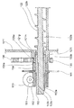
図5は駆動機構部129を示す斜視図であり、図6は駆動機構部129の要部を示す断面図である。尚、図5は駆動機構部129を収納する筐体を取り外した状態を図4の裏面側から見た図である。   FIG. 5 is a perspective view showing the drive mechanism 129, and FIG. 6 is a cross-sectional view showing the main part of the drive mechanism 129. As shown in FIG. FIG. 5 is a view of the state where the housing for housing the drive mechanism portion 129 is removed as seen from the back side of FIG.

図5に示すように、駆動機構部129は、前述のジョイント130の他に、ギア列132〜135と、第1撹拌ギア136と、第2撹拌ギア138、モータ150と、モータ150に接続されるウオームギア151、152と、検出板161を備える。   As shown in FIG. 5, the drive mechanism 129 is connected to the gear trains 132 to 135, the first stirring gear 136, the second stirring gear 138, the motor 150, and the motor 150 in addition to the joint 130 described above. Worm gears 151 and 152, and a detection plate 161.

ギア列132〜135及び第1及び第2撹拌ギア136、138は、夫々平歯車からなり、ジョイント130の回転駆動力をギア132からギア135へ、更に第1及び第2撹拌ギア136、138へと順次伝達し、第1及び第2撹拌部材123、124を回転させる。   The gear trains 132 to 135 and the first and second agitation gears 136 and 138 are respectively spur gears, and the rotational driving force of the joint 130 is transferred from the gear 132 to the gear 135 and further to the first and second agitation gears 136 and 138. Are sequentially transmitted to rotate the first and second stirring members 123 and 124.

第1撹拌ギア136は第1撹拌部材123(図3参照)に接続され第1撹拌部材123を回転駆動させる。つまり、第1撹拌部材123の軸部123aは、ホッパー容器121の側壁121fに回転自在に支持されるとともホッパー容器121の側壁121fから外側に突出して設けられており、第1撹拌ギア136はこの突出した軸部123aに一体に取り付けられる。   The first stirring gear 136 is connected to the first stirring member 123 (see FIG. 3) and rotates the first stirring member 123. That is, the shaft portion 123a of the first stirring member 123 is rotatably supported on the side wall 121f of the hopper container 121 and is provided to protrude outward from the side wall 121f of the hopper container 121. The first stirring gear 136 is The protruding shaft portion 123a is integrally attached.

第2撹拌ギア138は第2撹拌部材124(図3参照)に接続され第2撹拌部材124を回転駆動させる。つまり、第2撹拌部材124の軸部124aは、ホッパー容器121の側壁121fに回転自在に支持されるとともにホッパー容器121の側壁121fから外側に突出して設けられており、第2撹拌ギア138はこの突出した軸部124aに一体に取り付けられる。   The second stirring gear 138 is connected to the second stirring member 124 (see FIG. 3), and rotates the second stirring member 124. That is, the shaft portion 124a of the second agitating member 124 is rotatably supported on the side wall 121f of the hopper container 121 and protrudes outward from the side wall 121f of the hopper container 121. The second agitating gear 138 It is integrally attached to the protruding shaft portion 124a.

第1撹拌ギア136と第2撹拌ギア138との間にはアイドルギア137が設けられる。アイドルギア137は、ホッパー容器121の側壁121fに回転自在に設けられ、第1撹拌ギア136と第2撹拌ギア138の両方に噛合する。第1撹拌ギア136が回転するとアイドルギア137を介して第2撹拌ギア138は第1撹拌ギア136と同じ方向に回転する。これによって、第1及び第2撹拌部材123、124が回転しホッパー容器121内のトナーが撹拌される。   An idle gear 137 is provided between the first stirring gear 136 and the second stirring gear 138. The idle gear 137 is rotatably provided on the side wall 121f of the hopper container 121 and meshes with both the first stirring gear 136 and the second stirring gear 138. When the first stirring gear 136 rotates, the second stirring gear 138 rotates in the same direction as the first stirring gear 136 via the idle gear 137. As a result, the first and second stirring members 123 and 124 rotate, and the toner in the hopper container 121 is stirred.

第2撹拌ギア138の歯数は第1撹拌ギア136の歯数に対して多く設定され、第1及び第2撹拌ギア136、138が回転すると、第2撹拌部材124(図3参照)は比較的に低速で回転し、ホッパー容器121内の多量のトナーを緩やかに撹拌して、一方、第1撹拌部材123(図3参照)は比較的に高速で回転し、搬送部材122(図3参照)側へ搬送するための少量のトナーを迅速に撹拌することになる。   The number of teeth of the second stirring gear 138 is set to be larger than the number of teeth of the first stirring gear 136. When the first and second stirring gears 136 and 138 rotate, the second stirring member 124 (see FIG. 3) is compared. The first agitating member 123 (see FIG. 3) rotates at a relatively high speed, and the conveying member 122 (see FIG. 3). A small amount of toner to be conveyed to the) side is rapidly stirred.

ギア列132〜135のうち、ジョイントギア132はジョイント軸131に一体に設けられる。このジョイント軸131は図5の右側まで延び、ジョイント軸131の右端部には前述のジョイント130(図略、図4参照)が一体に設けられる。ジョイント130が回転するとジョイントギア132は回転駆動する。尚、ジョイントギア132とジョイント軸131及びジョイント130は一体で回転すればよく、ジョイントギア132とジョイント軸131及びジョイント130を樹脂で一体に成型してもよいし、またジョイント軸131とジョイント130を一体に形成してもよいし、またジョイントギア132とジョイント軸131を一体に形成してもよい。   Of the gear trains 132 to 135, the joint gear 132 is provided integrally with the joint shaft 131. The joint shaft 131 extends to the right side in FIG. 5, and the joint 130 (not shown, see FIG. 4) is integrally provided at the right end of the joint shaft 131. When the joint 130 rotates, the joint gear 132 is driven to rotate. The joint gear 132, the joint shaft 131, and the joint 130 may be rotated integrally, the joint gear 132, the joint shaft 131, and the joint 130 may be integrally molded with resin, and the joint shaft 131 and the joint 130 may be molded together. The joint gear 132 and the joint shaft 131 may be formed integrally.

また、ギア列132〜135のうち、第1中間ギア133と第2中間ギア134は、同軸に並べて一体形成された二段ギアであり、ホッパー容器121の側壁121fに固設された固定軸139に回転自在に設けられる。第1中間ギア133はジョイントギア132に噛合し、第2中間ギア134は第3中間ギア135に噛合する。   Of the gear trains 132 to 135, the first intermediate gear 133 and the second intermediate gear 134 are two-stage gears that are coaxially arranged and integrally formed, and are fixed shafts 139 fixed to the side wall 121 f of the hopper container 121. Is provided rotatably. The first intermediate gear 133 meshes with the joint gear 132, and the second intermediate gear 134 meshes with the third intermediate gear 135.

第3中間ギア135はホッパー容器121の側壁121fに形成した軸受けに回転自在に設けられ、第2中間ギア134に噛合するとともに第1撹拌ギア136にも噛合している。   The third intermediate gear 135 is rotatably provided on a bearing formed on the side wall 121 f of the hopper container 121, and meshes with the second intermediate gear 134 and also meshes with the first agitation gear 136.

従って、現像器14側の回転駆動力がジョイント130に付与されると、ジョイント軸131が回転し、ジョイントギア132及び第1〜第3中間ギア133〜135を介して、第1及び第2撹拌ギア136、138が回転駆動し、これによって、第1及び第2撹拌部材123、124が回転しホッパー容器121内のトナーが撹拌される。   Therefore, when the rotational driving force on the developing device 14 side is applied to the joint 130, the joint shaft 131 rotates and the first and second agitation are performed via the joint gear 132 and the first to third intermediate gears 133 to 135. The gears 136 and 138 are rotationally driven, whereby the first and second stirring members 123 and 124 are rotated and the toner in the hopper container 121 is stirred.

搬送部材122(図3参照)の回転駆動はモータ150を駆動源として行なわれる。モータ150は、ウオームギア151、152を介して搬送部材122を回転駆動し、モータ150の軸をホッパー容器121の側壁121fに対して平行に固設される。モータ150の駆動出力軸にはウオーム151が固定され、ウオーム151は伝達軸153に設けたウオームホイル152に噛合して、伝達軸153は搬送部材122と同軸で一体に設けられることで、モータ150が回転駆動すると、搬送部材122は回転させられる。   The rotation of the conveying member 122 (see FIG. 3) is performed using the motor 150 as a driving source. The motor 150 rotationally drives the conveying member 122 via the worm gears 151 and 152, and the shaft of the motor 150 is fixed in parallel to the side wall 121 f of the hopper container 121. A worm 151 is fixed to the drive output shaft of the motor 150, the worm 151 meshes with a worm wheel 152 provided on the transmission shaft 153, and the transmission shaft 153 is provided coaxially and integrally with the conveying member 122. Is rotated, the conveying member 122 is rotated.

図6に示すように、伝達軸153は、筒状をなし、その外周面153bにウオームホイル152を一体に形成し、その内周面153aに搬送部材122の軸部122aを嵌装する。   As shown in FIG. 6, the transmission shaft 153 has a cylindrical shape, a worm wheel 152 is integrally formed on the outer peripheral surface 153b, and the shaft portion 122a of the conveying member 122 is fitted on the inner peripheral surface 153a.

更に、伝達軸153の内周面153aには平坦面153cが形成され、一方、搬送部材122の軸部122aには、伝達軸153の内周面153aに対向する平坦面122cが形成される。これによって、伝達軸153が搬送部材122の軸部122aに嵌装されると、搬送部材122は伝達軸153と一体に回転することになる。尚、伝達軸153と搬送部材122の軸部122aを一体に形成し、ウオームホイル152を別部材とし、後でウオームホイル152を伝達軸153に一体に取り付けるように構成してもよい。また、搬送部材122の軸部122aと伝達軸153とウオームホイル152とを一体に形成するようにしてもよい。このように伝達軸153が搬送部材122の軸部122aと同軸に設けられ一体で回転するのであれば、ウオームホイル152と伝達軸153と搬送部材122の軸部122aは適宜一体に設ければよい。   Further, a flat surface 153 c is formed on the inner peripheral surface 153 a of the transmission shaft 153, while a flat surface 122 c that faces the inner peripheral surface 153 a of the transmission shaft 153 is formed on the shaft portion 122 a of the transport member 122. Accordingly, when the transmission shaft 153 is fitted to the shaft portion 122 a of the transport member 122, the transport member 122 rotates integrally with the transmission shaft 153. The transmission shaft 153 and the shaft portion 122a of the conveying member 122 may be integrally formed, the worm wheel 152 may be a separate member, and the worm wheel 152 may be attached to the transmission shaft 153 later. Further, the shaft portion 122a, the transmission shaft 153, and the worm wheel 152 of the conveying member 122 may be integrally formed. As described above, if the transmission shaft 153 is provided coaxially with the shaft portion 122a of the conveying member 122 and rotates integrally, the worm wheel 152, the transmission shaft 153, and the shaft portion 122a of the conveying member 122 may be integrally provided as appropriate. .

また、ホッパー容器121の側壁121fにはフランジ部が形成され、このフランジ部の内径側には内側軸受け面121iが形成され、また、フランジ部の外径側には外側軸受け面121hと、外側軸受け面121hの周上に直立する当接面121gとが形成される。   Further, a flange portion is formed on the side wall 121f of the hopper container 121, an inner bearing surface 121i is formed on the inner diameter side of the flange portion, and an outer bearing surface 121h and an outer bearing are formed on the outer diameter side of the flange portion. A contact surface 121g is formed upright on the circumference of the surface 121h.

側壁121fの外側軸受け面121hには前述の第3中間ギア135の軸受け孔135aが回転自在に嵌装される。更に、第3中間ギア135は側壁121fの当接面121gと係止筒154の当接面154aとに軸方向の両側を挟まれる。これによって、第3中間ギア135は軸方向に移動することなく回転するようにホッパー容器121の側壁121fに保持されることになる。尚、係止筒154は伝達軸153の外周面153bに固設されている。一方、側壁121fの内側軸受け面121iには伝達軸153の外周面153bが回転自在に嵌装される。   The bearing hole 135a of the third intermediate gear 135 is rotatably fitted to the outer bearing surface 121h of the side wall 121f. Further, the third intermediate gear 135 is sandwiched on both sides in the axial direction between the contact surface 121g of the side wall 121f and the contact surface 154a of the locking cylinder 154. As a result, the third intermediate gear 135 is held on the side wall 121f of the hopper container 121 so as to rotate without moving in the axial direction. The locking cylinder 154 is fixed to the outer peripheral surface 153b of the transmission shaft 153. On the other hand, the outer peripheral surface 153b of the transmission shaft 153 is rotatably fitted to the inner bearing surface 121i of the side wall 121f.

従って、伝達軸153と第3中間ギア135は交差して配置されることになる。つまり、伝達軸153の軸芯と第3中間ギア135の回転軸とは同軸となるように配置され、第3中間ギア135は側壁121fの外側軸受け面121hに嵌合して伝達軸153の周りで回転する。一方、伝達軸153は第3中間ギア135の軸受け孔135a内で側壁121fの内側軸受け面121iに嵌合して回転する   Therefore, the transmission shaft 153 and the third intermediate gear 135 are arranged so as to cross each other. In other words, the shaft center of the transmission shaft 153 and the rotation shaft of the third intermediate gear 135 are arranged so as to be coaxial, and the third intermediate gear 135 is fitted to the outer bearing surface 121h of the side wall 121f to surround the transmission shaft 153. Rotate with. On the other hand, the transmission shaft 153 is fitted in the inner bearing surface 121i of the side wall 121f in the bearing hole 135a of the third intermediate gear 135 and rotates.

このような駆動機構部129の構成において、モータ150が回転駆動すると、モータ150のウオーム151と伝達軸153のウオームホイル152との噛合によって伝達軸153は減速回転し、伝達軸153と一体に設けた搬送部材122は回転し、そしてホッパー容器121内トナーは送出口121b(図3参照)に搬送される。   In such a configuration of the drive mechanism 129, when the motor 150 is driven to rotate, the transmission shaft 153 rotates at a reduced speed due to the engagement between the worm 151 of the motor 150 and the worm wheel 152 of the transmission shaft 153, and is provided integrally with the transmission shaft 153. The conveying member 122 rotates, and the toner in the hopper container 121 is conveyed to the delivery port 121b (see FIG. 3).

また、伝達軸153の外周面153bには、周方向に複数の孔が形成された検出板161が固設される。この検出板161は図示しないフォトインターラプターとともに、搬送部材122の回転数を検出するものである。つまり、搬送部材122の回転にともない検出板161が回転するとき、フォトインターラプターから投光した光が検出板161の複数の孔を通過し、フォトインターラプターの受光素子がこの通過光を検知する。フォトインターラプターはこの検知した光のパルス数に基づいて搬送部材122の回転数を検出する。搬送部材122が回転しているときには、中間ホッパー120の送出口121bから現像器14にトナーが供給されているが、所定量のトナーを現像器14に供給するために、所定のトナー量に対応する回転数になると、フォトインターラプターのパルス信号に基づいて、モータ150の駆動を停止し、現像器14へのトナーの供給が完了する。   A detection plate 161 having a plurality of holes formed in the circumferential direction is fixed to the outer peripheral surface 153b of the transmission shaft 153. This detection plate 161 detects the number of rotations of the conveying member 122 together with a photo interrupter (not shown). That is, when the detection plate 161 rotates with the rotation of the conveying member 122, the light projected from the photo interrupter passes through the plurality of holes of the detection plate 161, and the light receiving element of the photo interrupter detects this passing light. . The photo interrupter detects the number of rotations of the conveying member 122 based on the detected number of pulses of light. When the conveying member 122 is rotating, toner is supplied to the developing device 14 from the delivery port 121b of the intermediate hopper 120. In order to supply a predetermined amount of toner to the developing device 14, the toner corresponds to a predetermined amount of toner. When the number of rotations reaches, the driving of the motor 150 is stopped based on the pulse signal of the photo interrupter, and the supply of toner to the developing device 14 is completed.

上記実施形態によれば、中間ホッパー120は、トナーを貯留する貯留容器121と、貯留容器121内で回転してトナーを撹拌する第1及び第2撹拌部材123、124と、第1及び第2撹拌部材123、124により撹拌されたトナーを現像器14に供給するために回転する搬送部材122とを備える。更に、中間ホッパー120は、搬送部材122を回転駆動させるモータ150と、現像器14側の駆動部材によって回転駆動させられるジョイント130と、ジョイント130から第1及び第2撹拌部材123、124に回転駆動力を伝達する第3中間ギア135とを備える。   According to the embodiment, the intermediate hopper 120 includes the storage container 121 that stores the toner, the first and second stirring members 123 and 124 that rotate in the storage container 121 and stir the toner, and the first and second. And a conveying member 122 that rotates to supply the toner agitated by the agitating members 123 and 124 to the developing device 14. Furthermore, the intermediate hopper 120 is rotationally driven from the joint 130 to the first and second stirring members 123 and 124 by the motor 150 that rotationally drives the transport member 122, the joint 130 that is rotationally driven by the driving member on the developing device 14 side. And a third intermediate gear 135 for transmitting force.

この構成によると、第1及び第2撹拌部材123、124と搬送部材122は互いに独立して回転し、第1及び第2撹拌部材123、124は現像器14側の駆動部材によって回転駆動しトナーを撹拌するので、現像器14が作動するときにトナー撹拌が行なわれ、トナーの流動性は良くなる。   According to this configuration, the first and second agitating members 123 and 124 and the conveying member 122 rotate independently of each other, and the first and second agitating members 123 and 124 are rotationally driven by the driving member on the developing device 14 side, and the toner. Therefore, the toner is agitated when the developing device 14 is operated, and the fluidity of the toner is improved.

また、この構成によると、中間ホッパー120から現像器14にトナーを補給する毎に中間ホッパー120内のトナーを撹拌することがないので、過度な撹拌がなくなり、トナーの劣化が抑えられる。   Further, according to this configuration, since the toner in the intermediate hopper 120 is not stirred every time the toner is supplied from the intermediate hopper 120 to the developing device 14, excessive stirring is eliminated and toner deterioration is suppressed.

また、この構成によると、トナーコンテナ110から中間ホッパー120へトナーを補給するとき、搬送部材122を駆動することなく中間ホッパー120内に補給されたトナーを撹拌することができる。   Further, according to this configuration, when the toner is supplied from the toner container 110 to the intermediate hopper 120, the toner supplied into the intermediate hopper 120 can be agitated without driving the conveying member 122.

また、この構成によると、第1及び第2撹拌部材123、124を回転駆動するモータ等の駆動部材を別途設ける必要がないので中間ホッパー120が小型になり、また、中間ホッパー120をコストダウンすることができる。   In addition, according to this configuration, it is not necessary to separately provide a driving member such as a motor that rotationally drives the first and second agitating members 123 and 124, so that the intermediate hopper 120 is reduced in size and the intermediate hopper 120 is reduced in cost. be able to.

また、この構成によると、搬送部材122と第1及び第2撹拌部材123、124とは互いに独立して回転駆動することで、第1及び第2撹拌部材123、124の回転負荷を受けることなく、搬送部材122は回転し、搬送部材122の回転が安定し中間ホッパー120から現像器14にトナーを安定して正確に供給することができる。   In addition, according to this configuration, the conveying member 122 and the first and second stirring members 123 and 124 are driven to rotate independently of each other without receiving the rotational load of the first and second stirring members 123 and 124. The conveying member 122 rotates, the rotation of the conveying member 122 is stabilized, and the toner can be stably and accurately supplied from the intermediate hopper 120 to the developing device 14.

また、上記実施形態によれば、モータ150からの回転駆動力を搬送部材122に伝達する伝達軸153が設けられ、この伝達軸153の軸芯と第3中間ギア135の回転軸とは同軸となるように配置され、第3中間ギア135は伝達軸153の周りで自由回転する。これによって、第3中間ギア135、伝達軸153等の駆動機構が装置内に大きな容積を占有することがなく、装置が小型化する。   Further, according to the above embodiment, the transmission shaft 153 that transmits the rotational driving force from the motor 150 to the conveying member 122 is provided, and the axis of the transmission shaft 153 and the rotation shaft of the third intermediate gear 135 are coaxial. The third intermediate gear 135 rotates freely around the transmission shaft 153. As a result, the drive mechanism such as the third intermediate gear 135 and the transmission shaft 153 does not occupy a large volume in the apparatus, and the apparatus is downsized.

また、上記実施形態によれば、ジョイント130と第1及び第2撹拌部材123、124とを接続するギア列132〜135を備え、第3中間ギア135は複数の平歯車からなるギア列132〜135の一つの平歯車であり、モータ150の駆動出力軸にはウオーム151が固定され、伝達軸153にはウオームホイル152が設けられる。これによって、ジョイント130と第1及び第2撹拌部材123、124とに接続するギア列132〜135のギアの配置と数を適宜設定することで、第1及び第2撹拌部材123、124は貯留容器121内の撹拌効率の良い位置に配置することができる。また、搬送部材122はウオームギア151、152によって回転駆動されるので、装置内に大きな容積を占有することがなく、装置が小型化する。   Moreover, according to the said embodiment, it has the gear trains 132-135 which connect the joint 130 and the 1st and 2nd stirring members 123 and 124, and the 3rd intermediate | middle gear 135 is the gear train 132- consisting of several spur gears. 135 is a spur gear, a worm 151 is fixed to the drive output shaft of the motor 150, and a worm wheel 152 is provided on the transmission shaft 153. Accordingly, the first and second stirring members 123 and 124 are stored by appropriately setting the arrangement and number of gears 132 to 135 connected to the joint 130 and the first and second stirring members 123 and 124. The container 121 can be disposed at a position where the stirring efficiency is good. Further, since the conveying member 122 is rotationally driven by the worm gears 151 and 152, a large volume is not occupied in the apparatus, and the apparatus is downsized.

また、上記実施形態によれば、搬送部材122は回転自在な軸部122aとこの軸部122aの周りに形成される螺旋羽根122bとを有し、伝達軸153は搬送部材122の軸部122aと同軸で一体に設けられる。これによって、モータ150による回転駆動力を搬送部材122に確実に伝達することができ、中間ホッパー120から現像器14へのトナー供給量が安定する。   In addition, according to the above embodiment, the conveying member 122 includes the rotatable shaft portion 122 a and the spiral blade 122 b formed around the shaft portion 122 a, and the transmission shaft 153 is connected to the shaft portion 122 a of the conveying member 122. Coaxially and integrally provided. Accordingly, the rotational driving force by the motor 150 can be reliably transmitted to the conveying member 122, and the amount of toner supplied from the intermediate hopper 120 to the developing device 14 is stabilized.

尚、上記実施形態では、モノクロ用画像形成装置に搭載されるトナー補給装置に適用した例を示したが、本発明はこれに限らず、カラー複写機、またはカラープリンタ等の各色毎に対応するトナー補給装置を搭載した画像形成装置においても、各色毎の現像器側の駆動部材によって、各トナー補給装置の撹拌部材を適宜回転させるようにすることが可能であり、トナー補給装置内で過剰に撹拌されるのを防ぐことができる。   In the above-described embodiment, an example in which the present invention is applied to a toner replenishing device mounted on a monochrome image forming apparatus has been described. However, the present invention is not limited to this and corresponds to each color such as a color copying machine or a color printer. Even in an image forming apparatus equipped with a toner replenishing device, it is possible to appropriately rotate the stirring member of each toner replenishing device by a driving member on the developing device side for each color. Stirring can be prevented.

また、上記実施形態では、トナー補給装置を中間ホッパー120に適用した例を示したが、本発明はこれに限らず、現像器14に対して着脱自在であり、貯留した新たなトナーを現像器14に直接補給するトナーコンテナ等のトナー補給装置に適用してもよい。   In the above-described embodiment, an example in which the toner replenishing device is applied to the intermediate hopper 120 has been described. The present invention may be applied to a toner replenishing device such as a toner container that replenishes the toner directly.

また、上記実施形態では、第1及び第2撹拌部材123、124を備える構成を示したが、本発明はこれに限らず、一つ、また三つ以上の撹拌部材を中間ホッパー120内に配置する構成にしてもよい。また、第1及び第2撹拌部材123、124はパドル状の羽根で形成される構成を示したが、本発明はこれに限らず、第1及び第2撹拌部材123、124は軸方向に螺旋状に延びる羽根で形成してもよい。この場合も上記と同様の効果を奏する。   In the above embodiment, the first and second stirring members 123 and 124 are shown. However, the present invention is not limited to this, and one or three or more stirring members are arranged in the intermediate hopper 120. You may make it the structure to carry out. Moreover, although the 1st and 2nd stirring members 123 and 124 showed the structure formed with a paddle-shaped blade | wing, this invention is not restricted to this, The 1st and 2nd stirring members 123 and 124 are spiral in an axial direction. You may form with the blade | wing extended in a shape. In this case, the same effect as described above can be obtained.

また、上記実施形態では、第1及び第2撹拌部材123、124を上下方向に対して傾斜するように配置する構成を示したが、本発明はこれに限らず、第1及び第2撹拌部材123、124を水平方向、または上下方向に並列するように配置してもよい。この場合も上記と同様の効果を奏する。   Moreover, in the said embodiment, although the structure which has arrange | positioned so that the 1st and 2nd stirring members 123 and 124 may incline with respect to an up-down direction was shown, this invention is not limited to this, The 1st and 2nd stirring members 123 and 124 may be arranged in parallel in the horizontal direction or the vertical direction. In this case, the same effect as described above can be obtained.

また、上記実施形態では、ジョイント130の回転駆動力を第1及び第2撹拌ギア136、138へ伝達するためにギア列132〜135を配置する構成を示したが、本発明はこれに限らず、1枚のギアによってジョイント130の回転駆動力を第1及び第2撹拌ギア136、138へ伝達するように構成してもよいし、また、4枚以外の枚数でギア列を構成してもよい。この場合も上記実施形態と同様に撹拌部材と搬送部材は互いに独立して回転駆動し、上記と同様の効果を奏する。   Moreover, in the said embodiment, although the structure which arrange | positions the gear trains 132-135 in order to transmit the rotational drive force of the joint 130 to the 1st and 2nd stirring gears 136 and 138 was shown, this invention is not limited to this. The rotational driving force of the joint 130 may be transmitted to the first and second stirring gears 136 and 138 by one gear, or the gear train may be configured by a number other than four. Good. Also in this case, the agitating member and the conveying member are driven to rotate independently from each other as in the above embodiment, and the same effect as described above can be obtained.

また、上記実施形態では、モータ150の軸にはウオーム151が設けられ、伝達軸153にはウオームホイル152が設けられる構成を示したが、本発明はこれに限らず、モータ150の軸と伝達軸153に夫々平歯車を設けて、モータ150の軸をホッパー容器121の側壁121fに対して直角に配置する構成にしてもよい。この場合も上記実施形態と同様に撹拌部材と搬送部材は互いに独立して回転駆動し、上記と同様の効果を奏する。   Further, in the above embodiment, the configuration is shown in which the worm 151 is provided on the shaft of the motor 150 and the worm wheel 152 is provided on the transmission shaft 153. However, the present invention is not limited to this, and the shaft and the transmission of the motor 150 are transmitted. A spur gear may be provided on each of the shafts 153 so that the shaft of the motor 150 is disposed at a right angle to the side wall 121f of the hopper container 121. Also in this case, the agitating member and the conveying member are driven to rotate independently from each other as in the above embodiment, and the same effect as described above can be obtained.

また、上記実施形態では、伝達軸153は搬送部材122の軸部122aと同軸で一体に設けられる構成を示したが、本発明はこれに限らず、伝達軸にギアを設けて、また搬送部材122の軸部122aにギアを設けて、この二つのギアに中間ギアが噛合する構成にしてもよい。この場合も上記実施形態と同様に撹拌部材と搬送部材は互いに独立して回転駆動し、上記と同様の効果を奏する。   Moreover, in the said embodiment, although the transmission shaft 153 showed the structure provided coaxially and integrally with the axial part 122a of the conveyance member 122, this invention is not restricted to this, A gear is provided in a transmission shaft, and a conveyance member is also provided. A gear may be provided on the shaft portion 122a of 122, and an intermediate gear may be engaged with the two gears. Also in this case, the agitating member and the conveying member are driven to rotate independently from each other as in the above embodiment, and the same effect as described above can be obtained.

本発明は、電子写真方式を利用した複写機、プリンタ、ファクシミリ、それらの複合機等の画像形成装置に備えられる現像器にトナーを供給するトナー補給装置及びそれを備えた画像形成装置に利用することができる。   The present invention is used for a toner replenishing device that supplies toner to a developing device provided in an image forming apparatus such as a copying machine, a printer, a facsimile, or a composite machine using an electrophotographic system, and an image forming apparatus including the toner replenishing device. be able to.

1 画像形成装置
14 現像器
95 トナー補給口
110 トナーコンテナ
120 中間ホッパー(トナー補給装置)
121 ホッパー容器(貯留容器)
121a 受け入れ口
121b 送出口
121d 撹拌部材収納部
121e 搬送部材収納部
121f 側壁
121g 当接面
121h 外側軸受け面
121i 内側軸受け面
122 搬送部材
122a 軸部
122b 螺旋羽根
122c 平坦面
123 第1撹拌部材
123a 第1軸部
123b 第1羽根
124 第2撹拌部材
124a 第2軸部
124b 第2羽根
129 駆動機構部
130 ジョイント(連結部材)
131 ジョイント軸
132 ジョイントギア(ギア列)
133 第1中間ギア(ギア列)
134 第2中間ギア(ギア列)
135 第3中間ギア(中間ギア、ギア列)
136 第1撹拌ギア
137 アイドルギア
138 第2撹拌ギア
150 モータ
151 ウオーム
152 ウオームホイル
153 伝達軸
153a 内周面
153b 外周面
153c 平坦面
154 係止筒
154a 当接面
161 検出板
DESCRIPTION OF SYMBOLS 1 Image forming apparatus 14 Developing device 95 Toner supply port 110 Toner container 120 Intermediate hopper (toner supply device)
121 Hopper container (storage container)
121a Receiving port 121b Delivery port 121d Stirring member accommodating portion 121e Conveying member accommodating portion 121f Side wall 121g Contact surface 121h Outer bearing surface 121i Inner bearing surface 122 Conveying member 122a Shaft portion 122b Spiral blade 122c Flat surface 123 First stirring member 123a First Shaft portion 123b First blade 124 Second stirring member 124a Second shaft portion 124b Second blade 129 Drive mechanism portion 130 Joint (connection member)
131 Joint shaft 132 Joint gear (gear train)
133 1st intermediate gear (gear train)
134 Second intermediate gear (gear train)
135 Third intermediate gear (intermediate gear, gear train)
136 First stirring gear 137 Idle gear 138 Second stirring gear 150 Motor 151 Warm 152 Warm wheel 153 Transmission shaft 153a Inner peripheral surface 153b Outer peripheral surface 153c Flat surface 154 Locking cylinder 154a Contact surface 161 Detection plate

Claims (5)

トナーを貯留する貯留容器と、前記貯留容器内で回転してトナーを撹拌する撹拌部材と、前記撹拌部材により撹拌されたトナーを現像器に供給するために回転する搬送部材と、前記搬送部材を回転駆動させるモータと、現像器側の駆動部材によって回転駆動させられる連結部材と、前記連結部材から前記撹拌部材に回転駆動力を伝達する少なくとも一つの中間ギアとを備えるトナー補給装置。   A storage container for storing toner, an agitation member that rotates in the storage container to stir the toner, a conveyance member that rotates to supply the toner agitated by the agitation member to the developing device, and the conveyance member A toner replenishing device comprising: a motor for rotational driving; a connecting member that is rotationally driven by a driving member on a developing device; and at least one intermediate gear that transmits rotational driving force from the connecting member to the stirring member. 前記モータからの回転駆動力を前記搬送部材に伝達する伝達軸が設けられ、前記中間ギアの何れか一つの回転軸は前記伝達軸と同軸となるように配置され、前記伝達軸の周りで自由回転することを特徴とする請求項1に記載のトナー補給装置。   A transmission shaft for transmitting the rotational driving force from the motor to the conveying member is provided, and any one of the intermediate gears is disposed so as to be coaxial with the transmission shaft, and freely around the transmission shaft. The toner supply device according to claim 1, wherein the toner supply device rotates. 前記モータの駆動出力軸にはウオームが固定され、前記伝達軸には前記ウオームと噛み合うウオームホイルが設けられることを特徴とする請求項2に記載のトナー補給装置。   The toner replenishing device according to claim 2, wherein a worm is fixed to the drive output shaft of the motor, and a worm foil that meshes with the worm is provided on the transmission shaft. 前記搬送部材は、前記貯留容器に回転自在に支持される軸部と、前記軸部の周りに形成される螺旋羽根とを有し、前記伝達軸は前記搬送部材の軸部と同軸で一体に設けられることを特徴とする請求項2または請求項3に記載のトナー補給装置。   The transport member has a shaft portion rotatably supported by the storage container, and a spiral blade formed around the shaft portion, and the transmission shaft is coaxially and integrally formed with the shaft portion of the transport member. The toner replenishing device according to claim 2, wherein the toner replenishing device is provided. 請求項1〜請求項4のいずれかに記載のトナー補給装置が搭載された画像形成装置。   An image forming apparatus on which the toner replenishing device according to claim 1 is mounted.
JP2010062600A 2010-03-18 2010-03-18 Toner supply device and image forming apparatus with the same Pending JP2011197255A (en)

Priority Applications (1)

Application Number Priority Date Filing Date Title
JP2010062600A JP2011197255A (en) 2010-03-18 2010-03-18 Toner supply device and image forming apparatus with the same

Applications Claiming Priority (1)

Application Number Priority Date Filing Date Title
JP2010062600A JP2011197255A (en) 2010-03-18 2010-03-18 Toner supply device and image forming apparatus with the same

Publications (1)

Publication Number Publication Date
JP2011197255A true JP2011197255A (en) 2011-10-06

Family

ID=44875585

Family Applications (1)

Application Number Title Priority Date Filing Date
JP2010062600A Pending JP2011197255A (en) 2010-03-18 2010-03-18 Toner supply device and image forming apparatus with the same

Country Status (1)

Country Link
JP (1) JP2011197255A (en)

Cited By (2)

* Cited by examiner, † Cited by third party
Publication number Priority date Publication date Assignee Title
JP2014071303A (en) * 2012-09-28 2014-04-21 Kyocera Document Solutions Inc Image forming apparatus
JP2014081531A (en) * 2012-10-17 2014-05-08 Kyocera Document Solutions Inc Image forming apparatus

Similar Documents

Publication Publication Date Title
JP5171890B2 (en) Developing transport device, developing device including the same, toner cartridge, and cleaning unit
JP4738497B2 (en) Developing device and image forming apparatus using the same
JP4667512B2 (en) Developing device and image forming apparatus using the same
JP4709295B2 (en) Developing device and image forming apparatus using the same
JP5009348B2 (en) Image forming apparatus
KR101376823B1 (en) Toner container, image forming apparatus and method of driving toner container
JP5540142B2 (en) Developer container and image forming apparatus to which the container is applied
JP5005792B2 (en) Developing device and image forming apparatus having the same
JP2011197255A (en) Toner supply device and image forming apparatus with the same
JP2010197839A (en) Developing device and image forming apparatus using the same
JP5307063B2 (en) Image forming apparatus
JP4738501B2 (en) Developing device and image forming apparatus using the same
JP5612294B2 (en) Image forming apparatus
JP4738496B2 (en) Developing device and image forming apparatus using the same
JP2014123065A (en) Powder storage container and image forming apparatus
JP2010160253A (en) Developing device and image forming device using the same
JP2011064766A (en) Image forming apparatus
JP2013148723A (en) Toner storage container and image forming apparatus equipped with the same
JP2010164691A (en) Developing device and image forming apparatus using the same
JP5193923B2 (en) Developing device and image forming apparatus
JP5536532B2 (en) Developing device and image forming apparatus having the same
JP5422434B2 (en) Toner supply device and image forming apparatus having the same
JP2011002771A (en) Image forming apparatus
JP4951679B2 (en) Developing device and image forming apparatus having the same
JP5882425B2 (en) Image forming apparatus