EP2503242A2 - Brennkammerkopf mit Halterung für Dichtungen an Brennern in Gastrurbinen - Google Patents
Brennkammerkopf mit Halterung für Dichtungen an Brennern in Gastrurbinen Download PDFInfo
- Publication number
- EP2503242A2 EP2503242A2 EP12002047A EP12002047A EP2503242A2 EP 2503242 A2 EP2503242 A2 EP 2503242A2 EP 12002047 A EP12002047 A EP 12002047A EP 12002047 A EP12002047 A EP 12002047A EP 2503242 A2 EP2503242 A2 EP 2503242A2
- Authority
- EP
- European Patent Office
- Prior art keywords
- burner
- combustion chamber
- seal
- base plate
- recess
- Prior art date
- Legal status (The legal status is an assumption and is not a legal conclusion. Google has not performed a legal analysis and makes no representation as to the accuracy of the status listed.)
- Granted
Links
- 238000002485 combustion reaction Methods 0.000 title claims abstract description 50
- 238000011144 upstream manufacturing Methods 0.000 claims abstract description 14
- 238000007789 sealing Methods 0.000 claims description 7
- 239000002184 metal Substances 0.000 claims description 4
- 230000008719 thickening Effects 0.000 description 11
- 239000000243 solution Substances 0.000 description 8
- 238000013459 approach Methods 0.000 description 6
- 238000009434 installation Methods 0.000 description 3
- 238000004519 manufacturing process Methods 0.000 description 3
- 238000000034 method Methods 0.000 description 3
- 238000013461 design Methods 0.000 description 2
- 238000005304 joining Methods 0.000 description 2
- 241001156002 Anthonomus pomorum Species 0.000 description 1
- 230000003750 conditioning effect Effects 0.000 description 1
- 230000001419 dependent effect Effects 0.000 description 1
- 238000011161 development Methods 0.000 description 1
- 230000002349 favourable effect Effects 0.000 description 1
- 238000003780 insertion Methods 0.000 description 1
- 230000037431 insertion Effects 0.000 description 1
- 238000003754 machining Methods 0.000 description 1
- 238000012423 maintenance Methods 0.000 description 1
- 238000003825 pressing Methods 0.000 description 1
- 238000012545 processing Methods 0.000 description 1
- 125000006850 spacer group Chemical group 0.000 description 1
- 238000012360 testing method Methods 0.000 description 1
Images

Classifications
-
- F—MECHANICAL ENGINEERING; LIGHTING; HEATING; WEAPONS; BLASTING
- F23—COMBUSTION APPARATUS; COMBUSTION PROCESSES
- F23R—GENERATING COMBUSTION PRODUCTS OF HIGH PRESSURE OR HIGH VELOCITY, e.g. GAS-TURBINE COMBUSTION CHAMBERS
- F23R3/00—Continuous combustion chambers using liquid or gaseous fuel
- F23R3/28—Continuous combustion chambers using liquid or gaseous fuel characterised by the fuel supply
- F23R3/283—Attaching or cooling of fuel injecting means including supports for fuel injectors, stems, or lances
-
- F—MECHANICAL ENGINEERING; LIGHTING; HEATING; WEAPONS; BLASTING
- F23—COMBUSTION APPARATUS; COMBUSTION PROCESSES
- F23R—GENERATING COMBUSTION PRODUCTS OF HIGH PRESSURE OR HIGH VELOCITY, e.g. GAS-TURBINE COMBUSTION CHAMBERS
- F23R3/00—Continuous combustion chambers using liquid or gaseous fuel
- F23R3/002—Wall structures
-
- F—MECHANICAL ENGINEERING; LIGHTING; HEATING; WEAPONS; BLASTING
- F23—COMBUSTION APPARATUS; COMBUSTION PROCESSES
- F23R—GENERATING COMBUSTION PRODUCTS OF HIGH PRESSURE OR HIGH VELOCITY, e.g. GAS-TURBINE COMBUSTION CHAMBERS
- F23R2900/00—Special features of, or arrangements for continuous combustion chambers; Combustion processes therefor
- F23R2900/00012—Details of sealing devices
Definitions
- the invention relates to a combustion chamber head of a gas turbine, in detail, the invention relates to a combustion chamber head according to the features of the preamble of claim 1.
- a gasket around a burner of a gas turbine is shown disposed upstream of a base plate of the combustor, projecting through it and a heat shield into the combustion chamber and performing the same function as described above.
- the seal can not leave their intended place, but only be moved along the burner in the axial direction.
- the actual sealing force which is absolutely necessary for the generation and maintenance of the sealing function, is usually not provided by gas turbine combustors by a spring element, but by the pressure difference between the combustion chamber outside and the combustion chamber inside, which acts on the effective surface of the seal.
- a device which is the seal Positioned near the sealing surface without pressing it.
- the axial positioning is adjusted by a spacer disc, which is located between the base plate of the combustion chamber and the seal.
- the radial positioning of the seal prior to installation of the Burner is ensured by the shape of the recess in the base plate of the combustion chamber.
- the positioning of the seal in the radial and axial direction is made possible by crescent-shaped brackets, which are held by the bolts of the heat shield.
- the in the DE 44 27 222 A1 used shims are adapted to the dimensions of the recess, which slows down the assembly.
- the in the DE 100 48 864 A1 proposed mounts position two seals, so that when attaching the nuts on the bolts of the heat shields three components must be held, which also makes the assembly difficult.
- the Indian US 5,419,115 A and the US 5,463,864 A provided joining process in the confined space of the combustion chamber head is a difficult to perform process step with a difficult-to-test result. Overall, all proposed Solutions through the many components to be manufactured and joined complicated, expensive and difficult.
- the invention has for its object to provide a combustion chamber head of the type mentioned, which has a simple design and simple, cost-effective manufacturability a simple design of the burner seal and is easy and inexpensive to install.
- the combustion chamber head has a base plate which is provided with a central recess, in which at least one burner is arranged.
- the base plate is connected at its radially inner and outer regions with walls of the combustion chamber, in particular an inner and an outer wall of an annular combustion chamber (combustion chamber housing).
- a burner sealing the burner to the edge of the recess is provided.
- the burner seal according to the invention arranged upstream of the base plate and against a formed on the base plate, the edge of the central recess forming collar for conditioning brought. This seals the burner seal against the base plate.
- the invention provides that a holding element of the burner seal is designed in the form of a ring and is arranged upstream of the burner seal.
- the annular retaining element is engaged with at least one shoulder of the base plate. This approach can be designed for example in the form of a thickening.
- the annular holding element is provided with at least one locking tab, which is in engagement with the attachment of the base plate (thickening).
- the tab is preferably arranged on the inner ring of the annular retaining element, according to the invention it is also possible to form the tab on the outer ring of the annular retaining element.
- this preferably has a recess into which the tab can be introduced, in particular by deformation of the tab.
- the burner seal is funnel-shaped on its upstream side.
- the seal as in DE 100 48 864 A1 Provide upstream of the base plate of the combustion chamber, which can be brought to bear on a recess for carrying out the burner seal collar of the base plate to the plant a holder of the burner seal is a simple sheet metal ring with, for example, three outward tabs, which in recesses in the thickenings of Engage the base plate of the combustion chamber.
- the burner seal at the upstream end has a feed funnel, which facilitates the assembly of the burner and fulfills no further function during operation.
- the tabs on the annular seal retainer may be attached to the inner or outer edge of the seal retainer.
- the annular holding element (sheet metal ring) is placed over the burner seal, that the tabs come to rest next to the recesses in the three recesses of the thicker portions of the base plate. Then the tabs of the annular support member are pressed by a correspondingly shaped tool in the direction of the base plate and the annular support member rotated by a small angle. As a result, the tabs engage in the recesses of the thickening (of the approach) of the base plate so that the annular retaining element can not turn back, but the tabs can spring back to their original shape without being under tension.
- An anti-rotation device for the burner seal itself is not necessary for general operating experience and is therefore not made possible by the here pitched assembly.
- the integrated feed hopper eliminates the need for an additional component for this function, which in turn would need to be reliably and operationally secured. The costs for the production and installation of an anti-rotation device are saved as this function is not necessary.
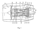
- the gas turbine engine 10 is an example of a turbomachine to which the invention may find application. However, it will be understood from the following that the invention can be used with other turbomachinery as well.
- the engine 10 is conventionally formed and includes in the flow direction one after another an air inlet 11, a fan 12 circulating in a housing, an intermediate pressure compressor 13, a high pressure compressor 14, combustion chambers 15, a high pressure turbine 16, an intermediate pressure turbine 17 and a low pressure turbine 18 and an exhaust nozzle 19, which are all arranged around a central engine axis 1.
- the intermediate pressure compressor 13 and the high pressure compressor 14 each include a plurality of stages, each of which includes a circumferentially extending array of fixed stationary vanes 20, commonly referred to as stator vanes, that radially inwardly from the engine casing 21 in an annular flow passage through the compressors 13, 14 protrude.
- the compressors further include an array of compressor blades 22 projecting radially outwardly from a rotatable drum or disc 26 coupled to hubs 27 of the high pressure turbine 16 and the intermediate pressure turbine 17, respectively.
- the turbine sections 16, 17, 18 have similar steps, comprising an array of fixed vanes 23 extending radially inward from the housing 21 into the housing annular flow channel through the turbines 16, 17, 18 protrude, and a subsequent arrangement of turbine blades 24 which project outwardly from a rotatable hub 27.
- the compressor drum or compressor disk 26 and the vanes 22 disposed thereon and the turbine rotor hub 27 and the turbine blades 24 disposed thereon rotate about the engine axis 1 during operation.
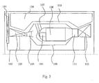
- the Fig. 2 shows in a simplified schematic representation of the area of a combustion chamber 108 of a gas turbine.
- This comprises an inner combustion chamber housing 109 and an outer combustion chamber housing 110.
- a combustion chamber head 107 is arranged, in which a burner 106 with arm and head is arranged.
- a compressor 103 is also connected to the drive shaft 102.
- the reference numeral 104 shows a side stream (bypass channel).
- the incoming air is passed through a compressor outlet guide 105 with diffuser.
- the flow exiting the combustion chamber 108 is performed by a turbine nozzle 111 and a turbine runner 112.
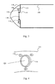
- the Fig. 3 shows a schematic detail view of an embodiment of the inventive solution.
- a base plate 113 is arranged at the upstream end region of the combustion chamber 108, which is provided with a recess which is delimited by a collar 118. Through the recess of the burner 106 is performed, as in the Fig. 1 and 2 is shown.
- the base plate 113 is provided with a projection 114 (thickening).
- the thickening 114 supports in a recess 115 a burner seal 116, which is annular, as known from the prior art.
- the burner seal 116 is held by a retaining element 117 (retaining ring), as described in the following figures.
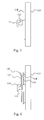
- the Fig. 4 shows a portion of the annular base plate 113, which is provided with the collar 118 which limits the recess 121 for the passage of the burner 106.
- Distributed around the circumference of the collar 118 are three lugs 114 (thickenings of the base plate 113).
- the Fig. 5 shows a schematic partial side sectional view of the base plate 113 with the collar 118 and a projection 114 with a recess 115.
- Die Fig. 6 shows the in Fig. 5 shown arrangement in the mounted state of the annular burner seal 116 and the retaining element 117 (retaining ring).
- the holding element 117 shows a locking tab (tab) 120, as will be described below.
- the Fig. 6 shows the arrangement of the locking tab 120 at the radially outer region of the retaining ring 117, as in the right half of the Fig. 8 is shown. There are three circumferentially distributed locking tabs (tabs) 120 shown.
- the Fig. 7 shows a variant in which the locking tab 120 is inserted into the recess 115 of the projection 114. It is thus shown the finished assembled state.
- the right half of the picture Fig. 8 shows variants of the locking tabs, namely a locking tab 120a of the seal holder (retaining ring 117).
- the variant of the locking tab 120b is arranged on the outside of the retaining ring 117, while the variant of the locking tab 120c is arranged on the inside of the retaining ring 117.
- the locking tabs 120b and 120c are each shown in the bent state.
Landscapes
- Engineering & Computer Science (AREA)
- Chemical & Material Sciences (AREA)
- Combustion & Propulsion (AREA)
- Mechanical Engineering (AREA)
- General Engineering & Computer Science (AREA)
- Turbine Rotor Nozzle Sealing (AREA)
Abstract
Description
- Die Erfindung bezieht sich auf einen Brennkammerkopf einer Gasturbine, im Einzelnen bezieht sich die Erfindung dabei auf einen Brennkammerkopf gemäß den Merkmalen des Oberbegriffs des Anspruches 1.
- In der
DE 44 27 222 A1 ist eine Dichtung um einen Brenner einer Gasturbine beschrieben, welcher stromab einer Grundplatte der Brennkammer angeordnet ist, durch ein Hitzeschild hindurch in die Brennkammer ragt und die Bewegungen zwischen dem Brenner, welcher im Brennkammergehäuse befestigt ist, und der Brennkammer selbst derart ausgleicht, dass keine inakzeptablen Leckagen entstehen. Im engeren Sinne gasdicht braucht diese Art der Dichtung nicht zu sein. - In der
DE 100 48 864 A1 wird eine Dichtung um einen Brenner einer Gasturbine dargestellt, welcher stromauf einer Grundplatte der Brennkammer angeordnet ist, durch sie und ein Hitzeschild hindurch in die Brennkammer ragt und die gleiche Funktion erfüllt, wie oben beschrieben. - Sobald der Brenner eingesetzt ist, kann die Dichtung ihren vorgesehenen Platz nicht mehr verlassen, sondern nur noch entlang des Brenners in axialer Richtung verschoben werden. Die eigentliche Dichtkraft, welche zur Erzeugung und Aufrechterhaltung der Dichtfunktion zwingend erforderlich ist, wird bei Gasturbinenbrennkammern üblicherweise nicht durch ein Federelement, sondern durch die Druckdifferenz zwischen der Brennkammeraußenseite und der Brennkammerinnenseite bereitgestellt, welche auf die wirksame Fläche der Dichtung wirkt.
- Bevor der Brenner allerdings eingesetzt ist und um sicherzustellen, dass sich die Dichtung beim Starten der Gasturbine nahe der Dichtfläche befindet und dann durch die entstehende Druckdifferenz auch wirklich an die Grundplatte der Brennkammer oder das Hitzeschild gedrückt wird, muss eine Vorrichtung vorgesehen werden, welche die Dichtung nahe der Dichtfläche positioniert, ohne sie anzudrücken. Bei der aus der
DE 44 27 222 A1 bekannten Lösung wird die axiale Positionierung durch eine Abstandsscheibe eingestellt, welche sich zwischen der Grundplatte der Brennkammer und der Dichtung befindet. Die radiale Positionierung der Dichtung vor dem Einbau des Brenners wird durch die Form der Ausnehmung in der Grundplatte der Brennkammer sichergestellt. Bei der aus derDE 100 48 864 A1 bekannten Lösung wird die Positionierung der Dichtung in radialer und axialer Richtung durch halbmondförmige Klammern ermöglicht, welche durch die Bolzen des Hitzeschildes gehalten werden. - Einen anderen Lösungsansatz zeigen die
US 5,419,115 A und dieUS 5,463,864 A . Hier wird die Führung und Dichtung des Brenners erst nach dem Hitzeschild von der stromab liegenden Seite des Brennkammerkopfes montiert und danach stromauf des Kopfes durch eine an diese Brenner-Führung gefügte ein- oder zweiteilige Halterung befestigt. Dies geschieht so, dass diese Vorrichtung aus Führung und Halterung noch geringe gleitende Bewegungen in radialer und lateraler Richtung durchführen kann, um wiederum das Einführen des Brenners zu ermöglichen und im Betrieb die Relativbewegungen zwischen Brennkammergehäuse, in welchem der Brenner befestigt ist, und der Brennkammer ausgeglichen werden können. In beiden Schriften werden unterschiedliche Ausformungen einer Verdrehsicherung für die Führung des Brenners und deren Dichtung dargestellt, welche zum Teil einstückig mit der Grundpatte der Brennkammer ausgeführt sind oder fest bzw. beweglich auf dieser befestigt werden. In derUS 5,524,438 A wird in einer weiteren Variation diese Verdrehsicherung durch einen Blechring mit radialen Laschen dargestellt, welche in Ausnehmungen benachbarter ringförmiger Bauteile eingreifen. Diese radialen Laschen werden bei der Montage nicht als elastische Elemente verwendet. - Bei den aus dem Stand der Technik bekannten Lösungen ergeben sich folgende Nachteile:
- Die in der
DE 44 27 222 A1 verwendeten Abstandsscheiben werden an die Maße der Vertiefung angepasst, was die Montage verlangsamt. Die in derDE 100 48 864 A1 vorgeschlagenen Halterungen positionieren zwei Dichtungen, so dass beim Ansetzen der Muttern auf die Bolzen der Hitzeschilder drei Bauteile festgehalten werden müssen, was die Montage ebenfalls schwierig gestaltet. Der in derUS 5,419,115 A und derUS 5,463,864 A vorgesehene Fügeprozess im beengten Bauraum des Brennkammerkopfes stellt einen schwierig auszuführenden Prozessschritt mit einem schwierig zu prüfenden Ergebnis dar. Insgesamt erscheinen alle vorgeschlagenen Lösungen durch die vielen zu fertigenden und zu fügenden Bauteile kompliziert, teuer und schwer. - Der Erfindung liegt die Aufgabe zugrunde, einen Brennkammerkopf der eingangs genannten Art zu schaffen, welcher bei einfachem Aufbau und einfacher, kostengünstiger Herstellbarkeit eine einfache Ausgestaltung der Brennerdichtung aufweist und einfach und kostengünstig montierbar ist.
- Erfindungsgemäß wird die Aufgabe durch die Merkmalskombination des Anspruchs 1 gelöst, die Unteransprüche zeigen weitere vorteilhafte Ausgestaltungen der Erfindung.
- Erfindungsgemäß ist somit vorgesehen, dass der Brennkammerkopf eine Grundplatte aufweist, welche mit einer zentrischen Ausnehmung versehen ist, in welcher zumindest ein Brenner angeordnet ist. Die Grundplatte ist an ihren radial inneren und äußeren Bereichen mit Wandungen der Brennkammer, insbesondere einer inneren und einer äußeren Wandung einer Ringbrennkammer (Brennkammergehäuse), verbunden. Weiterhin ist erfindungsgemäß eine den Brenner zum Rand der Ausnehmung abdichtende Brennerdichtung vorgesehen. Die Brennerdichtung ist erfindungsgemäß stromauf der Grundplatte angeordnet und gegen einen an der Grundplatte ausgebildeten, den Rand der zentrischen Ausnehmung bildenden Kragen zur Anlage bringbar. Hierdurch erfolgt eine Abdichtung der Brennerdichtung gegenüber der Grundplatte. Weiterhin ist erfindungsgemäß vorgesehen, dass ein Halteelement der Brennerdichtung in Form eines Rings ausgebildet ist und stromauf der Brennerdichtung angeordnet ist. Das ringförmige Halteelement ist mit zumindest einem Ansatz der Grundplatte in Eingriff. Dieser Ansatz kann beispielsweise in Form einer Aufdickung ausgebildet sein.
- In günstiger Weiterbildung der Erfindung ist vorgesehen, dass das ringförmige Halteelement mit zumindest einer Verriegelungslasche versehen ist, welche mit dem Ansatz der Grundplatte (Aufdickung) in Eingriff ist. Die Lasche ist bevorzugterweise am Innenring des ringförmigen Halteelements angeordnet, erfindungsgemäß ist es auch möglich, die Lasche am Außenring des ringförmigen Halteelements auszubilden.
- Um die Lasche in Eingriff mit dem Ansatz zu bringen, weist dieser bevorzugterweise eine Ausnehmung auf, in welche die Lasche einbringbar ist, insbesondere durch Verformung der Lasche.
- Um die Montage des Brenners zu erleichtern, ist es besonders günstig, wenn die Brennerdichtung an ihrer stromauf liegenden Seite trichterförmig ausgebildet ist.
- Erfindungsgemäß ist somit vorgesehen, die Dichtung, wie in
DE 100 48 864 A1 stromauf der Grundplatte der Brennkammer vorzusehen, wobei diese auf einem um die Ausnehmung zur Durchführung der Brennerdichtung umlaufenden Kragen der Grundplatte zur Anlage bringbar ist wobei eine Halterung der Brennerdichtung ein einfacher Blechring mit zum Beispiel drei nach außen stehenden Laschen ist, welche in Ausnehmungen in Aufdickungen der Grundplatte der Brennkammer eingreifen. Zugleich hat die Brennerdichtung am stromauf liegenden Ende einen Zuführtrichter, der die Montage des Brenners erleichtert und im Betrieb keine weitere Funktion mehr erfüllt. - Drei Ansätze der Aufdickungen der Grundplatte dienen während der mechanischen Bearbeitung des Brennkammerkopfes als permanente Referenz. Die Laschen an der ringförmigen Dichtungshalterung können am Innen- oder Außenrand der Dichtungshalterung angebracht sein.
- Zur Montage wird das ringförmige Halteelement (Blechring) so über die Brennerdichtung gelegt, dass die Laschen neben den Ausnehmungen in den drei Ausnehmungen der Aufdickungen der Grundplatte zu liegen kommen. Dann werden die Laschen des ringförmigen Halteelements durch ein entsprechend geformtes Werkzeug in Richtung Grundplatte gedrückt und das ringförmige Halteelement um einen kleinen Winkelbetrag verdreht. Dadurch greifen die Laschen so in die Ausnehmungen der Aufdickung (des Ansatzes) der Grundplatte ein, dass sich das ringförmige Halteelement nicht mehr zurückdrehen kann, die Laschen aber in ihre ursprüngliche Form zurückspringen können ohne weiterhin unter Spannung zu stehen. Eine Verdrehsicherung für die Brennerdichtung selbst ist nach allgemeiner Betriebserfahrung nicht notwendig und wird daher durch die hier aufgeschlagene Montage auch nicht ermöglicht.
- In der Herstellung der Brennkammer und auch später bei der Reparatur von beschädigten Brennkammern stehen dieselben Bezugspunkte in Form von Ansätzen von Aufdickungen für eine mechanische Bearbeitung der Brennkammer zur Verfügung. Zwischen Herstellung und Überholung der Brennkammer erfüllen diese Ansätze von Aufdickungen die Funktion einer Dichtungshalterung. Während der Montage wird die Brennerdichtung durch ein Werkzeug zentriert. Die Halterung der Brennerdichtung wird ebenfalls durch das Werkzeug zentriert und bewegt. Dadurch muss der Monteur nur ein Werkzeug anfassen und nicht drei Teile gleichzeitig. Hierdurch wird die Montage sicher und schnell ausgeführt und es sind keinerlei Fügeprozesse notwendig. Dies ermöglicht eine präzise, wiederholbare und leichte und kostengünstige Montage. Durch den spannungslosen Zustand der Halterung im eingerasteten Zustand kommt es in dieser auch zu keinen Ermüdungserscheinungen im Betrieb des Triebwerks. Während der gesamten Betriebsdauer der Brennerdichtung wird diese nahe am Brennkammerkopf gehalten. Die Dichtkraft wird durch die Druckdifferenz zwischen der die Brennkammer umströmenden Luft und der Luft in der Brennkammer und nicht durch die Halterung der Brennerdichtung erzeugt. Durch den integrierten Zuführtrichter wird kein zusätzliches Bauteil für diese Funktion benötigt, welches wiederum zuverlässig und betriebssicher befestigt werden müsste. Die Kosten für die Herstellung und Montage einer Verdrehsicherung werden eingespart, da diese Funktion nicht notwendig ist.
- Im Folgenden wird die Erfindung anhand von Ausführungsbeispielen in Verbindung mit der Zeichnung beschrieben. Dabei zeigt:
- Fig. 1
- eine schematische Darstellung eines Gasturbinentriebwerks gemäß der vorliegenden Erfindung,
- Fig. 2
- eine schematische vergrößerte Detailansicht einer erfindungsgemäßen Brennkammer mit zugehörigen Bauelementen der Gasturbine,
- Fig. 3
- eine vergrößerte Detail-Schnittansicht in schematischer Darstellung eines Ausführungsbeispiels der erfindungsgemäßen Lösung,
- Fig. 4
- eine perspektivische Teilansicht der Grundplatte mit Kragen,
- Fig. 5
- eine vereinfachte Teil-Seitenansicht der Frontplatte mit Kragen und Ansatz,
- Fig. 6
- eine Darstellung analog
Fig. 5 im montierten Zustand der Brennerdichtung und deren Halterung, - Fig. 7
- eine Darstellung, analog den
Fig. 5 und 6 , eines weiteren Ausführungsbeispiels mit montierter Brennerdichtung und Halterung, und - Fig. 8
- vereinfachte Darstellungen von Ausführungsbeispielen der erfindungsgemäßen Halterung.
- Das Gasturbinentriebwerk 10 gemäß
Fig. 1 ist ein Beispiel einer Turbomaschine, bei der die Erfindung Anwendung finden kann. Aus dem Folgenden wird jedoch klar, dass die Erfindung auch bei anderen Turbomaschinen verwendet werden kann. Das Triebwerk 10 ist in herkömmlicher Weise ausgebildet und umfasst in Strömungsrichtung hintereinander einen Lufteinlass 11, einen in einem Gehäuse umlaufenden Fan 12, einen Zwischendruckkompressor 13, einen Hochdruckkompressor 14, Brennkammern 15, eine Hochdruckturbine 16, eine Zwischendruckturbine 17 und eine Niederdruckturbine 18 sowie eine Abgasdüse 19, die sämtlich um eine zentrale Triebwerksachse 1 angeordnet sind. - Der Zwischendruckkompressor 13 und der Hochdruckkompressor 14 umfassen jeweils mehrere Stufen, von denen jede eine in Umfangsrichtung verlaufende Anordnung fester stationärer Leitschaufeln 20 aufweist, die allgemein als Statorschaufeln bezeichnet werden und die radial nach innen vom Triebwerksgehäuse 21 in einem ringförmigen Strömungskanal durch die Kompressoren 13, 14 vorstehen. Die Kompressoren weisen weiter eine Anordnung von Kompressorlaufschaufeln 22 auf, die radial nach außen von einer drehbaren Trommel oder Scheibe 26 vorstehen, die mit Naben 27 der Hochdruckturbine 16 bzw. der Zwischendruckturbine 17 gekoppelt sind.
- Die Turbinenabschnitte 16, 17, 18 weisen ähnliche Stufen auf, umfassend eine Anordnung von festen Leitschaufeln 23, die radial nach innen vom Gehäuse 21 in den ringförmigen Strömungskanal durch die Turbinen 16, 17, 18 vorstehen, und eine nachfolgende Anordnung von Turbinenschaufeln 24, die nach außen von einer drehbaren Nabe 27 vorstehen. Die Kompressortrommel oder Kompressorscheibe 26 und die darauf angeordneten Schaufeln 22 sowie die Turbinenrotornabe 27 und die darauf angeordneten Turbinenlaufschaufeln 24 drehen sich im Betrieb um die Triebwerksachse 1.
- Die
Fig. 2 zeigt in vereinfachter schematischer Darstellung den Bereich einer Brennkammer 108 einer Gasturbine. Diese umfasst ein inneres Brennkammergehäuse 109 sowie ein äußeres Brennkammergehäuse 110. Stromauf der Brennkammer 108 ist ein Brennkammerkopf 107 angeordnet, in welchem ein Brenner 106 mit Arm und Kopf angeordnet ist. Die Luftzuführung zu der Brennkammer 8 erfolgt über ein Frontgebläse 101 (Fan), welcher von einer Antriebswelle 102 angetrieben wird. Mit der Antriebswelle 102 ist auch ein Verdichter 103 verbunden. Das Bezugszeichen 104 zeigt einen Nebenstrom (Nebenstromkanal). Die anströmende Luft wird über ein Verdichteraustrittsleitrad 105 mit Diffuser geleitet. Die aus der Brennkammer 108 austretende Strömung wird durch ein Turbinenleitrad 111 sowie ein Turbinenlaufrad 112 durchgeführt. - Die
Fig. 3 zeigt in schematischer Detailansicht ein Ausführungsbeispiel der erfindungsgemäßen Lösung. Erfindungsgemäß ist am stromauf liegenden Endbereich der Brennkammer 108 eine Grundplatte 113 angeordnet, welche mit einer Ausnehmung versehen ist, welche durch einen Kragen 118 begrenzt wird. Durch die Ausnehmung wird der Brenner 106 durchgeführt, so wie dies in denFig. 1 und2 dargestellt ist. Die Grundplatte 113 ist mit einem Ansatz 114 (Aufdickung) versehen. Die Aufdickung 114 lagert in einer Ausnehmung 115 eine Brennerdichtung 116, welche ringförmig ausgebildet ist, so wie dies aus dem Stand der Technik bekannt ist. Die Brennerdichtung 116 wird über ein Halteelement 117 (Haltering) gehalten, so wie dies in den nachfolgenden Figuren beschrieben wird. - Die
Fig. 4 zeigt einen Teil der kreisringförmig ausgebildeten Grundplatte 113, welche mit dem Kragen 118 versehen ist, der die Ausnehmung 121 zur Durchführung des Brenners 106 begrenzt. Um den Umfang des Kragens 118 verteilt sind drei Ansätze 114 (Aufdickungen der Grundplatte 113) vorgesehen. - Die
Fig. 5 zeigt eine schematisierte Teil-Seitenschnittansicht der Grundplatte 113 mit dem Kragen 118 und einem Ansatz 114 mit einer Ausnehmung 115. DieFig. 6 zeigt die inFig. 5 dargestellte Anordnung im montierten Zustand der ringförmigen Brennerdichtung 116 sowie des Halteelements 117 (Haltering). Das Halteelement 117 zeigt eine Verriegelungslasche (Lasche) 120, so wie dies nachfolgend noch beschrieben werden wird. DieFig. 6 zeigt dabei die Anordnung der Verriegelungslasche 120 am radial äußeren Bereich des Halterings 117, so wie dies in der rechten Bildhälfte derFig. 8 dargestellt ist. Dort sind am Umfang verteilt drei Verriegelungslaschen (Laschen) 120 dargestellt. - Die
Fig. 7 zeigt eine Variante, bei welcher die Verriegelungslasche 120 in die Ausnehmung 115 des Ansatzes 114 eingebracht ist. Es ist somit der fertig montierte Zustand dargestellt. - Die rechte Bildhälfte der
Fig. 8 zeigt Varianten der Verriegelungslaschen, nämlich eine Verriegelungslasche 120a des Dichtungshalters (Haltering 117). Die Variante der Verriegelungslasche 120b ist außen an dem Haltering 117 angeordnet, während die Variante der Verriegelungslasche 120c innen am Haltering 117 angeordnet ist. Die Verriegelungslaschen 120b und 120c sind jeweils im gebogenen Zustand dargestellt. -
- 1
- Triebwerksachse
- 10
- Gasturbinentriebwerk
- 11
- Lufteinlass
- 12
- im Gehäuse umlaufender Fan
- 13
- Zwischendruckkompressor
- 14
- Hochdruckkompressor
- 15
- Brennkammern
- 16
- Hochdruckturbine
- 17
- Zwischendruckturbine
- 18
- Niederdruckturbine
- 19
- Abgasdüse
- 20
- Leitschaufeln
- 21
- Triebwerksgehäuse
- 22
- Kompressorlaufschaufeln
- 23
- Leitschaufeln
- 24
- Turbinenschaufeln
- 26
- Kompressortrommel oder -scheibe
- 27
- Turbinenrotornabe
- 28
- Abgaskonus
- 101
- Frontgebläse (Fan)
- 102
- Antriebswelle
- 103
- Verdichter
- 104
- Nebenstrom
- 105
- Verdichteraustrittsleitrad mit Diffuser
- 106
- Brenner mit Arm und Kopf
- 107
- Brennkammerkopf
- 108
- Brennkammer
- 109
- Inneres Brennkammergehäuse
- 110
- Äußeres Brennkammergehäuse
- 111
- Turbinenleitrad
- 112
- Turbinenlaufrad
- 113
- Grundplatte der Brennkammer 108
- 114
- Aufdickung der Grundplatte 113 / Ansatz
- 115
- Ausnehmung der Aufdickung 114
- 116
- Brennerdichtung
- 117
- Halterung der Brennerdichtung / Halteelement / Haltering
- 118
- Kragen der Grundplatte 113 zur Auflage der Brennerdichtung 116
- 119
- Abdeckung der Grundplatte 113
- 120a
- Verriegelungslasche des Dichtungshalters 117
- 120b
- gebogene Variante der Verriegelungslasche, außen am Dichtungshalter 117
- 120c
- gebogene Variante der Verriegelungslasche, innen am Dichtungshalter 117
- 121
- Ausnehmung
Claims (6)
- Brennkammerkopf einer Gasturbine mit einer Grundplatte (113), welche mit einer zentrischen Ausnehmung (121) versehen ist, in welcher zumindest ein Brenner (106) angeordnet ist, wobei die Grundplatte (113) mit Wandungen der Brennkammer (108) verbunden ist, sowie mit einer den Brenner (106) zum Rand der Ausnehmung (121) abdichtenden Brennerdichtung (116), dadurch gekennzeichnet, dass die Brennerdichtung (116) stromauf der Grundplatte (113) angeordnet ist und gegen einen an der Grundplatte (113) ausgebildeten, den Rand der zentrischen Ausnehmung (121) bildenden Kragen (118) zur Anlage bringbar ist und dass ein Halteelement (117) der Brennerdichtung (116) in Form eines Blechrings ausgebildet ist und stromauf der Brennerdichtung (116) angeordnet ist und mit zumindest einem Ansatz (114) der Grundplatte (113) spannungsfrei in Eingriff ist.
- Brennkammerkopf nach Anspruch 1, dadurch gekennzeichnet, dass das Halteelement (117) mit zumindest einer Verriegelungslasche (120a, 120b, 120c) versehen ist, welche mit dem Ansatz (114) spannungsfrei in Eingriff ist.
- Brennkammerkopf nach Anspruch 2, dadurch gekennzeichnet, dass die Lasche (120a, 120b, 120c) am Innenrand des ringförmigen Halteelements (117) angeordnet ist.
- Brennkammerkopf nach Anspruch 2, dadurch gekennzeichnet, dass die Lasche (120a, 120b, 120c) am Außenrand des ringförmigen Halteelements (117) angeordnet ist.
- Brennkammerkopf nach einem der Ansprüche 2 bis 4, dadurch gekennzeichnet, dass der Ansatz (114) mit zumindest einer Ausnehmung (115) zum Eingriff der Verriegelungslasche (120a, 120b, 120c) versehen ist.
- Brennkammerkopf nach einem der Ansprüche 1 bis 5, dadurch gekennzeichnet, dass die Brennerdichtung (113) an ihrer stromauf liegenden Seite zur Einführung des Brenners (106) trichterförmig ausgebildet ist.
Applications Claiming Priority (1)
| Application Number | Priority Date | Filing Date | Title |
|---|---|---|---|
| DE102011014972A DE102011014972A1 (de) | 2011-03-24 | 2011-03-24 | Brennkammerkopf mit Halterungen für Dichtungen an Brennern in Gasturbinen |
Publications (3)
| Publication Number | Publication Date |
|---|---|
| EP2503242A2 true EP2503242A2 (de) | 2012-09-26 |
| EP2503242A3 EP2503242A3 (de) | 2017-11-08 |
| EP2503242B1 EP2503242B1 (de) | 2020-03-04 |
Family
ID=45932107
Family Applications (1)
| Application Number | Title | Priority Date | Filing Date |
|---|---|---|---|
| EP12002047.4A Active EP2503242B1 (de) | 2011-03-24 | 2012-03-22 | Brennkammerkopf mit Halterung für Dichtungen an Brennern in Gasturbinen |
Country Status (3)
| Country | Link |
|---|---|
| US (1) | US9222675B2 (de) |
| EP (1) | EP2503242B1 (de) |
| DE (1) | DE102011014972A1 (de) |
Cited By (1)
| Publication number | Priority date | Publication date | Assignee | Title |
|---|---|---|---|---|
| DE102013007443A1 (de) | 2013-04-30 | 2014-10-30 | Rolls-Royce Deutschland Ltd & Co Kg | Brennerdichtung für Gasturbinen-Brennkammerkopf und Hitzeschild |
Families Citing this family (7)
| Publication number | Priority date | Publication date | Assignee | Title |
|---|---|---|---|---|
| EP3039344B1 (de) * | 2013-08-30 | 2018-08-08 | United Technologies Corporation | Wirblerhalterungsverbindung für eine gasturbinenbrennkammer |
| GB201321193D0 (en) | 2013-12-02 | 2014-01-15 | Rolls Royce Plc | A combustion chamber assembly |
| FR3015639B1 (fr) * | 2013-12-20 | 2018-08-31 | Safran Aircraft Engines | Chambre de combustion dans une turbomachine |
| GB2543803B (en) * | 2015-10-29 | 2019-10-30 | Rolls Royce Plc | A combustion chamber assembly |
| GB2547906B (en) * | 2016-03-02 | 2019-07-03 | Rolls Royce Plc | A bladed rotor arrangement |
| US11428410B2 (en) | 2019-10-08 | 2022-08-30 | Rolls-Royce Corporation | Combustor for a gas turbine engine with ceramic matrix composite heat shield and seal retainer |
| US11466858B2 (en) | 2019-10-11 | 2022-10-11 | Rolls-Royce Corporation | Combustor for a gas turbine engine with ceramic matrix composite sealing element |
Citations (5)
| Publication number | Priority date | Publication date | Assignee | Title |
|---|---|---|---|---|
| US5419115A (en) | 1994-04-29 | 1995-05-30 | United Technologies Corporation | Bulkhead and fuel nozzle guide assembly for an annular combustion chamber |
| US5463864A (en) | 1993-12-27 | 1995-11-07 | United Technologies Corporation | Fuel nozzle guide for a gas turbine engine combustor |
| DE4427222A1 (de) | 1994-08-01 | 1996-02-08 | Bmw Rolls Royce Gmbh | Hitzeschild für eine Gasturbinen-Brennkammer |
| US5524438A (en) | 1994-12-15 | 1996-06-11 | United Technologies Corporation | Segmented bulkhead liner for a gas turbine combustor |
| DE10048864A1 (de) | 2000-10-02 | 2002-04-11 | Rolls Royce Deutschland | Brennkammerkopf für eine Gasturbine |
Family Cites Families (11)
| Publication number | Priority date | Publication date | Assignee | Title |
|---|---|---|---|---|
| US4870818A (en) * | 1986-04-18 | 1989-10-03 | United Technologies Corporation | Fuel nozzle guide structure and retainer for a gas turbine engine |
| FR2662784B1 (fr) * | 1990-06-05 | 1992-08-14 | Snecma | Ensemble d'injection pour turbomachine, comprenant un bol de prevaporisation. |
| FR2679010B1 (fr) * | 1991-07-10 | 1993-09-24 | Snecma | Chambre de combustion de turbomachine a bols de prevaporisation demontables. |
| US5577379A (en) * | 1994-12-15 | 1996-11-26 | United Technologies Corporation | Fuel nozzle guide retainer assembly |
| US7140189B2 (en) * | 2004-08-24 | 2006-11-28 | Pratt & Whitney Canada Corp. | Gas turbine floating collar |
| US7131273B2 (en) * | 2004-12-17 | 2006-11-07 | General Electric Company | Gas turbine engine carburetor with flat retainer connecting primary and secondary swirlers |
| US7628019B2 (en) * | 2005-03-21 | 2009-12-08 | United Technologies Corporation | Fuel injector bearing plate assembly and swirler assembly |
| US7617689B2 (en) * | 2006-03-02 | 2009-11-17 | Honeywell International Inc. | Combustor dome assembly including retaining ring |
| FR2903171B1 (fr) * | 2006-06-29 | 2008-10-17 | Snecma Sa | Agencement a liaison par crabot pour chambre de combustion de turbomachine |
| US7926280B2 (en) * | 2007-05-16 | 2011-04-19 | Pratt & Whitney Canada Corp. | Interface between a combustor and fuel nozzle |
| US8689563B2 (en) * | 2009-07-13 | 2014-04-08 | United Technologies Corporation | Fuel nozzle guide plate mistake proofing |
-
2011
- 2011-03-24 DE DE102011014972A patent/DE102011014972A1/de not_active Withdrawn
-
2012
- 2012-03-22 EP EP12002047.4A patent/EP2503242B1/de active Active
- 2012-03-23 US US13/428,633 patent/US9222675B2/en not_active Expired - Fee Related
Patent Citations (5)
| Publication number | Priority date | Publication date | Assignee | Title |
|---|---|---|---|---|
| US5463864A (en) | 1993-12-27 | 1995-11-07 | United Technologies Corporation | Fuel nozzle guide for a gas turbine engine combustor |
| US5419115A (en) | 1994-04-29 | 1995-05-30 | United Technologies Corporation | Bulkhead and fuel nozzle guide assembly for an annular combustion chamber |
| DE4427222A1 (de) | 1994-08-01 | 1996-02-08 | Bmw Rolls Royce Gmbh | Hitzeschild für eine Gasturbinen-Brennkammer |
| US5524438A (en) | 1994-12-15 | 1996-06-11 | United Technologies Corporation | Segmented bulkhead liner for a gas turbine combustor |
| DE10048864A1 (de) | 2000-10-02 | 2002-04-11 | Rolls Royce Deutschland | Brennkammerkopf für eine Gasturbine |
Cited By (3)
| Publication number | Priority date | Publication date | Assignee | Title |
|---|---|---|---|---|
| DE102013007443A1 (de) | 2013-04-30 | 2014-10-30 | Rolls-Royce Deutschland Ltd & Co Kg | Brennerdichtung für Gasturbinen-Brennkammerkopf und Hitzeschild |
| EP2799776A1 (de) | 2013-04-30 | 2014-11-05 | Rolls-Royce Deutschland Ltd & Co KG | Brennerdichtung für Gasturbinen-Brennkammerkopf und Hitzeschild |
| US10041415B2 (en) | 2013-04-30 | 2018-08-07 | Rolls-Royce Deutschland Ltd & Co Kg | Burner seal for gas-turbine combustion chamber head and heat shield |
Also Published As
| Publication number | Publication date |
|---|---|
| US9222675B2 (en) | 2015-12-29 |
| US20120240595A1 (en) | 2012-09-27 |
| DE102011014972A1 (de) | 2012-09-27 |
| EP2503242B1 (de) | 2020-03-04 |
| EP2503242A3 (de) | 2017-11-08 |
Similar Documents
| Publication | Publication Date | Title |
|---|---|---|
| EP2503242B1 (de) | Brennkammerkopf mit Halterung für Dichtungen an Brennern in Gasturbinen | |
| EP2503246B1 (de) | Segmentierter Brennkammerkopf | |
| EP3056813B1 (de) | Abdichtung eines randspalts zwischen effusionsschindeln einer gasturbinenbrennkammer | |
| EP2845999B1 (de) | Verfahren zum Auswuchten und zur Montage eines Turbinenrotors | |
| EP2873921A1 (de) | Brennkammerhitzeabschirmelement einer Gasturbine | |
| DE102010064047A1 (de) | Strömungsmaschine | |
| EP2799776A1 (de) | Brennerdichtung für Gasturbinen-Brennkammerkopf und Hitzeschild | |
| EP2714518A1 (de) | Gasturbinentriebwerk mit teleskopartigem lufteinlass der triebwerksverkleidung | |
| EP3954876B1 (de) | Düsenring für einen abgasturbolader | |
| EP2966352A1 (de) | Brennkammer einer gasturbine mit verschraubtem brennkammerkopf | |
| EP1573172B1 (de) | Turbine und Arbeitsverfahren zum Ausbau der Leitschaufeln einer Turbine | |
| DE102011016917A1 (de) | Gasturbinenbrennkammer mit einer Halterung einer Dichtung für ein Anbauteil | |
| EP2980481A1 (de) | Fluggasturbine mit einer dichtung zur abdichtung einer zündkerze an der brennkammerwand einer gasturbine | |
| EP2831379B1 (de) | Trägerring | |
| EP2730744B1 (de) | Abgasturbolader | |
| DE102014209057A1 (de) | Gasturbinengehäuseanordnung | |
| EP2781695A1 (de) | Leitvorrichtung einer Abgasturbine | |
| EP3170987B1 (de) | Innenringsystem für eine strömungsmaschine | |
| DE102012014109A1 (de) | Zwischenscheibendichtung einer Gasturbine | |
| DE102017201349A1 (de) | Brennkammeranordnung einer Gasturbine | |
| EP3022395B1 (de) | Einsatzelement, ringsegment, gasturbine, montageverfahren | |
| DE102014222320A1 (de) | Brennkammerwand einer Gasturbine mit Kühlung für einen Mischluftlochrand | |
| DE102015213786A1 (de) | Fluggasturbine mit in-situ-Wartungsöffnung mittels demontierbarer Leitschaufel eines Hochdruckkompressors | |
| DE102015224990A1 (de) | Verfahren zur Montage einer Brennkammer eines Gasturbinentriebwerks | |
| DE102015225825A1 (de) | Gasturbinenbrennkammer mit ringförmigem Hitzeschild |
Legal Events
| Date | Code | Title | Description |
|---|---|---|---|
| PUAI | Public reference made under article 153(3) epc to a published international application that has entered the european phase |
Free format text: ORIGINAL CODE: 0009012 |
|
| AK | Designated contracting states |
Kind code of ref document: A2 Designated state(s): AL AT BE BG CH CY CZ DE DK EE ES FI FR GB GR HR HU IE IS IT LI LT LU LV MC MK MT NL NO PL PT RO RS SE SI SK SM TR |
|
| AX | Request for extension of the european patent |
Extension state: BA ME |
|
| PUAL | Search report despatched |
Free format text: ORIGINAL CODE: 0009013 |
|
| AK | Designated contracting states |
Kind code of ref document: A3 Designated state(s): AL AT BE BG CH CY CZ DE DK EE ES FI FR GB GR HR HU IE IS IT LI LT LU LV MC MK MT NL NO PL PT RO RS SE SI SK SM TR |
|
| AX | Request for extension of the european patent |
Extension state: BA ME |
|
| RIC1 | Information provided on ipc code assigned before grant |
Ipc: F23R 3/28 20060101AFI20171005BHEP Ipc: F23R 3/00 20060101ALI20171005BHEP |
|
| RAP1 | Party data changed (applicant data changed or rights of an application transferred) |
Owner name: ROLLS-ROYCE DEUTSCHLAND LTD & CO KG |
|
| STAA | Information on the status of an ep patent application or granted ep patent |
Free format text: STATUS: REQUEST FOR EXAMINATION WAS MADE |
|
| 17P | Request for examination filed |
Effective date: 20180425 |
|
| RBV | Designated contracting states (corrected) |
Designated state(s): AL AT BE BG CH CY CZ DE DK EE ES FI FR GB GR HR HU IE IS IT LI LT LU LV MC MK MT NL NO PL PT RO RS SE SI SK SM TR |
|
| STAA | Information on the status of an ep patent application or granted ep patent |
Free format text: STATUS: EXAMINATION IS IN PROGRESS |
|
| 17Q | First examination report despatched |
Effective date: 20181017 |
|
| GRAP | Despatch of communication of intention to grant a patent |
Free format text: ORIGINAL CODE: EPIDOSNIGR1 |
|
| STAA | Information on the status of an ep patent application or granted ep patent |
Free format text: STATUS: GRANT OF PATENT IS INTENDED |
|
| INTG | Intention to grant announced |
Effective date: 20190918 |
|
| GRAS | Grant fee paid |
Free format text: ORIGINAL CODE: EPIDOSNIGR3 |
|
| GRAA | (expected) grant |
Free format text: ORIGINAL CODE: 0009210 |
|
| STAA | Information on the status of an ep patent application or granted ep patent |
Free format text: STATUS: THE PATENT HAS BEEN GRANTED |
|
| AK | Designated contracting states |
Kind code of ref document: B1 Designated state(s): AL AT BE BG CH CY CZ DE DK EE ES FI FR GB GR HR HU IE IS IT LI LT LU LV MC MK MT NL NO PL PT RO RS SE SI SK SM TR |
|
| REG | Reference to a national code |
Ref country code: GB Ref legal event code: FG4D Free format text: NOT ENGLISH |
|
| RIN1 | Information on inventor provided before grant (corrected) |
Inventor name: GERENDAS, MIKLOS, DR.-ING. |
|
| REG | Reference to a national code |
Ref country code: CH Ref legal event code: EP |
|
| REG | Reference to a national code |
Ref country code: AT Ref legal event code: REF Ref document number: 1240807 Country of ref document: AT Kind code of ref document: T Effective date: 20200315 |
|
| REG | Reference to a national code |
Ref country code: DE Ref legal event code: R096 Ref document number: 502012015822 Country of ref document: DE |
|
| REG | Reference to a national code |
Ref country code: IE Ref legal event code: FG4D Free format text: LANGUAGE OF EP DOCUMENT: GERMAN |
|
| PGFP | Annual fee paid to national office [announced via postgrant information from national office to epo] |
Ref country code: GB Payment date: 20200327 Year of fee payment: 9 |
|
| PG25 | Lapsed in a contracting state [announced via postgrant information from national office to epo] |
Ref country code: FI Free format text: LAPSE BECAUSE OF FAILURE TO SUBMIT A TRANSLATION OF THE DESCRIPTION OR TO PAY THE FEE WITHIN THE PRESCRIBED TIME-LIMIT Effective date: 20200304 Ref country code: NO Free format text: LAPSE BECAUSE OF FAILURE TO SUBMIT A TRANSLATION OF THE DESCRIPTION OR TO PAY THE FEE WITHIN THE PRESCRIBED TIME-LIMIT Effective date: 20200604 Ref country code: RS Free format text: LAPSE BECAUSE OF FAILURE TO SUBMIT A TRANSLATION OF THE DESCRIPTION OR TO PAY THE FEE WITHIN THE PRESCRIBED TIME-LIMIT Effective date: 20200304 |
|
| REG | Reference to a national code |
Ref country code: NL Ref legal event code: MP Effective date: 20200304 |
|
| PG25 | Lapsed in a contracting state [announced via postgrant information from national office to epo] |
Ref country code: HR Free format text: LAPSE BECAUSE OF FAILURE TO SUBMIT A TRANSLATION OF THE DESCRIPTION OR TO PAY THE FEE WITHIN THE PRESCRIBED TIME-LIMIT Effective date: 20200304 Ref country code: SE Free format text: LAPSE BECAUSE OF FAILURE TO SUBMIT A TRANSLATION OF THE DESCRIPTION OR TO PAY THE FEE WITHIN THE PRESCRIBED TIME-LIMIT Effective date: 20200304 Ref country code: GR Free format text: LAPSE BECAUSE OF FAILURE TO SUBMIT A TRANSLATION OF THE DESCRIPTION OR TO PAY THE FEE WITHIN THE PRESCRIBED TIME-LIMIT Effective date: 20200605 Ref country code: LV Free format text: LAPSE BECAUSE OF FAILURE TO SUBMIT A TRANSLATION OF THE DESCRIPTION OR TO PAY THE FEE WITHIN THE PRESCRIBED TIME-LIMIT Effective date: 20200304 Ref country code: BG Free format text: LAPSE BECAUSE OF FAILURE TO SUBMIT A TRANSLATION OF THE DESCRIPTION OR TO PAY THE FEE WITHIN THE PRESCRIBED TIME-LIMIT Effective date: 20200604 |
|
| REG | Reference to a national code |
Ref country code: LT Ref legal event code: MG4D |
|
| PG25 | Lapsed in a contracting state [announced via postgrant information from national office to epo] |
Ref country code: NL Free format text: LAPSE BECAUSE OF FAILURE TO SUBMIT A TRANSLATION OF THE DESCRIPTION OR TO PAY THE FEE WITHIN THE PRESCRIBED TIME-LIMIT Effective date: 20200304 |
|
| PG25 | Lapsed in a contracting state [announced via postgrant information from national office to epo] |
Ref country code: CZ Free format text: LAPSE BECAUSE OF FAILURE TO SUBMIT A TRANSLATION OF THE DESCRIPTION OR TO PAY THE FEE WITHIN THE PRESCRIBED TIME-LIMIT Effective date: 20200304 Ref country code: IS Free format text: LAPSE BECAUSE OF FAILURE TO SUBMIT A TRANSLATION OF THE DESCRIPTION OR TO PAY THE FEE WITHIN THE PRESCRIBED TIME-LIMIT Effective date: 20200704 Ref country code: PT Free format text: LAPSE BECAUSE OF FAILURE TO SUBMIT A TRANSLATION OF THE DESCRIPTION OR TO PAY THE FEE WITHIN THE PRESCRIBED TIME-LIMIT Effective date: 20200729 Ref country code: ES Free format text: LAPSE BECAUSE OF FAILURE TO SUBMIT A TRANSLATION OF THE DESCRIPTION OR TO PAY THE FEE WITHIN THE PRESCRIBED TIME-LIMIT Effective date: 20200304 Ref country code: RO Free format text: LAPSE BECAUSE OF FAILURE TO SUBMIT A TRANSLATION OF THE DESCRIPTION OR TO PAY THE FEE WITHIN THE PRESCRIBED TIME-LIMIT Effective date: 20200304 Ref country code: LT Free format text: LAPSE BECAUSE OF FAILURE TO SUBMIT A TRANSLATION OF THE DESCRIPTION OR TO PAY THE FEE WITHIN THE PRESCRIBED TIME-LIMIT Effective date: 20200304 Ref country code: SM Free format text: LAPSE BECAUSE OF FAILURE TO SUBMIT A TRANSLATION OF THE DESCRIPTION OR TO PAY THE FEE WITHIN THE PRESCRIBED TIME-LIMIT Effective date: 20200304 Ref country code: EE Free format text: LAPSE BECAUSE OF FAILURE TO SUBMIT A TRANSLATION OF THE DESCRIPTION OR TO PAY THE FEE WITHIN THE PRESCRIBED TIME-LIMIT Effective date: 20200304 Ref country code: SK Free format text: LAPSE BECAUSE OF FAILURE TO SUBMIT A TRANSLATION OF THE DESCRIPTION OR TO PAY THE FEE WITHIN THE PRESCRIBED TIME-LIMIT Effective date: 20200304 |
|
| REG | Reference to a national code |
Ref country code: CH Ref legal event code: PL |
|
| REG | Reference to a national code |
Ref country code: DE Ref legal event code: R097 Ref document number: 502012015822 Country of ref document: DE |
|
| REG | Reference to a national code |
Ref country code: BE Ref legal event code: MM Effective date: 20200331 |
|
| PG25 | Lapsed in a contracting state [announced via postgrant information from national office to epo] |
Ref country code: MC Free format text: LAPSE BECAUSE OF FAILURE TO SUBMIT A TRANSLATION OF THE DESCRIPTION OR TO PAY THE FEE WITHIN THE PRESCRIBED TIME-LIMIT Effective date: 20200304 Ref country code: LU Free format text: LAPSE BECAUSE OF NON-PAYMENT OF DUE FEES Effective date: 20200322 |
|
| PLBE | No opposition filed within time limit |
Free format text: ORIGINAL CODE: 0009261 |
|
| STAA | Information on the status of an ep patent application or granted ep patent |
Free format text: STATUS: NO OPPOSITION FILED WITHIN TIME LIMIT |
|
| PG25 | Lapsed in a contracting state [announced via postgrant information from national office to epo] |
Ref country code: DK Free format text: LAPSE BECAUSE OF FAILURE TO SUBMIT A TRANSLATION OF THE DESCRIPTION OR TO PAY THE FEE WITHIN THE PRESCRIBED TIME-LIMIT Effective date: 20200304 Ref country code: CH Free format text: LAPSE BECAUSE OF NON-PAYMENT OF DUE FEES Effective date: 20200331 Ref country code: IE Free format text: LAPSE BECAUSE OF NON-PAYMENT OF DUE FEES Effective date: 20200322 Ref country code: IT Free format text: LAPSE BECAUSE OF FAILURE TO SUBMIT A TRANSLATION OF THE DESCRIPTION OR TO PAY THE FEE WITHIN THE PRESCRIBED TIME-LIMIT Effective date: 20200304 Ref country code: LI Free format text: LAPSE BECAUSE OF NON-PAYMENT OF DUE FEES Effective date: 20200331 |
|
| 26N | No opposition filed |
Effective date: 20201207 |
|
| PG25 | Lapsed in a contracting state [announced via postgrant information from national office to epo] |
Ref country code: SI Free format text: LAPSE BECAUSE OF FAILURE TO SUBMIT A TRANSLATION OF THE DESCRIPTION OR TO PAY THE FEE WITHIN THE PRESCRIBED TIME-LIMIT Effective date: 20200304 Ref country code: BE Free format text: LAPSE BECAUSE OF NON-PAYMENT OF DUE FEES Effective date: 20200331 Ref country code: PL Free format text: LAPSE BECAUSE OF FAILURE TO SUBMIT A TRANSLATION OF THE DESCRIPTION OR TO PAY THE FEE WITHIN THE PRESCRIBED TIME-LIMIT Effective date: 20200304 |
|
| REG | Reference to a national code |
Ref country code: AT Ref legal event code: MM01 Ref document number: 1240807 Country of ref document: AT Kind code of ref document: T Effective date: 20200322 |
|
| PG25 | Lapsed in a contracting state [announced via postgrant information from national office to epo] |
Ref country code: AT Free format text: LAPSE BECAUSE OF NON-PAYMENT OF DUE FEES Effective date: 20200322 |
|
| GBPC | Gb: european patent ceased through non-payment of renewal fee |
Effective date: 20210322 |
|
| PG25 | Lapsed in a contracting state [announced via postgrant information from national office to epo] |
Ref country code: GB Free format text: LAPSE BECAUSE OF NON-PAYMENT OF DUE FEES Effective date: 20210322 |
|
| PGFP | Annual fee paid to national office [announced via postgrant information from national office to epo] |
Ref country code: DE Payment date: 20220329 Year of fee payment: 11 |
|
| PG25 | Lapsed in a contracting state [announced via postgrant information from national office to epo] |
Ref country code: TR Free format text: LAPSE BECAUSE OF FAILURE TO SUBMIT A TRANSLATION OF THE DESCRIPTION OR TO PAY THE FEE WITHIN THE PRESCRIBED TIME-LIMIT Effective date: 20200304 Ref country code: MT Free format text: LAPSE BECAUSE OF FAILURE TO SUBMIT A TRANSLATION OF THE DESCRIPTION OR TO PAY THE FEE WITHIN THE PRESCRIBED TIME-LIMIT Effective date: 20200304 Ref country code: CY Free format text: LAPSE BECAUSE OF FAILURE TO SUBMIT A TRANSLATION OF THE DESCRIPTION OR TO PAY THE FEE WITHIN THE PRESCRIBED TIME-LIMIT Effective date: 20200304 |
|
| PGFP | Annual fee paid to national office [announced via postgrant information from national office to epo] |
Ref country code: FR Payment date: 20220325 Year of fee payment: 11 |
|
| PG25 | Lapsed in a contracting state [announced via postgrant information from national office to epo] |
Ref country code: MK Free format text: LAPSE BECAUSE OF FAILURE TO SUBMIT A TRANSLATION OF THE DESCRIPTION OR TO PAY THE FEE WITHIN THE PRESCRIBED TIME-LIMIT Effective date: 20200304 Ref country code: AL Free format text: LAPSE BECAUSE OF FAILURE TO SUBMIT A TRANSLATION OF THE DESCRIPTION OR TO PAY THE FEE WITHIN THE PRESCRIBED TIME-LIMIT Effective date: 20200304 |
|
| P01 | Opt-out of the competence of the unified patent court (upc) registered |
Effective date: 20230528 |
|
| REG | Reference to a national code |
Ref country code: DE Ref legal event code: R119 Ref document number: 502012015822 Country of ref document: DE |
|
| PG25 | Lapsed in a contracting state [announced via postgrant information from national office to epo] |
Ref country code: FR Free format text: LAPSE BECAUSE OF NON-PAYMENT OF DUE FEES Effective date: 20230331 Ref country code: DE Free format text: LAPSE BECAUSE OF NON-PAYMENT OF DUE FEES Effective date: 20231003 |