EP2503186A2 - Automatic transmission - Google Patents
Automatic transmission Download PDFInfo
- Publication number
- EP2503186A2 EP2503186A2 EP12000915A EP12000915A EP2503186A2 EP 2503186 A2 EP2503186 A2 EP 2503186A2 EP 12000915 A EP12000915 A EP 12000915A EP 12000915 A EP12000915 A EP 12000915A EP 2503186 A2 EP2503186 A2 EP 2503186A2
- Authority
- EP
- European Patent Office
- Prior art keywords
- speed ratio
- speed
- continuously variable
- sun gear
- variable transmission
- Prior art date
- Legal status (The legal status is an assumption and is not a legal conclusion. Google has not performed a legal analysis and makes no representation as to the accuracy of the status listed.)
- Withdrawn
Links
- 230000005540 biological transmission Effects 0.000 title claims abstract description 95
- 230000008878 coupling Effects 0.000 claims abstract description 55
- 238000010168 coupling process Methods 0.000 claims abstract description 55
- 238000005859 coupling reaction Methods 0.000 claims abstract description 55
- 238000010586 diagram Methods 0.000 claims description 22
- 230000007935 neutral effect Effects 0.000 description 11
- 238000010276 construction Methods 0.000 description 5
- 230000035939 shock Effects 0.000 description 3
- 230000004323 axial length Effects 0.000 description 2
Images

Classifications
-
- F—MECHANICAL ENGINEERING; LIGHTING; HEATING; WEAPONS; BLASTING
- F16—ENGINEERING ELEMENTS AND UNITS; GENERAL MEASURES FOR PRODUCING AND MAINTAINING EFFECTIVE FUNCTIONING OF MACHINES OR INSTALLATIONS; THERMAL INSULATION IN GENERAL
- F16H—GEARING
- F16H9/00—Gearings for conveying rotary motion with variable gear ratio, or for reversing rotary motion, by endless flexible members
- F16H9/02—Gearings for conveying rotary motion with variable gear ratio, or for reversing rotary motion, by endless flexible members without members having orbital motion
- F16H9/04—Gearings for conveying rotary motion with variable gear ratio, or for reversing rotary motion, by endless flexible members without members having orbital motion using belts, V-belts, or ropes
- F16H9/12—Gearings for conveying rotary motion with variable gear ratio, or for reversing rotary motion, by endless flexible members without members having orbital motion using belts, V-belts, or ropes engaging a pulley built-up out of relatively axially-adjustable parts in which the belt engages the opposite flanges of the pulley directly without interposed belt-supporting members
-
- F—MECHANICAL ENGINEERING; LIGHTING; HEATING; WEAPONS; BLASTING
- F16—ENGINEERING ELEMENTS AND UNITS; GENERAL MEASURES FOR PRODUCING AND MAINTAINING EFFECTIVE FUNCTIONING OF MACHINES OR INSTALLATIONS; THERMAL INSULATION IN GENERAL
- F16H—GEARING
- F16H37/00—Combinations of mechanical gearings, not provided for in groups F16H1/00 - F16H35/00
- F16H37/02—Combinations of mechanical gearings, not provided for in groups F16H1/00 - F16H35/00 comprising essentially only toothed or friction gearings
- F16H37/021—Combinations of mechanical gearings, not provided for in groups F16H1/00 - F16H35/00 comprising essentially only toothed or friction gearings toothed gearing combined with continuously variable friction gearing
- F16H37/022—Combinations of mechanical gearings, not provided for in groups F16H1/00 - F16H35/00 comprising essentially only toothed or friction gearings toothed gearing combined with continuously variable friction gearing the toothed gearing having orbital motion
-
- F—MECHANICAL ENGINEERING; LIGHTING; HEATING; WEAPONS; BLASTING
- F16—ENGINEERING ELEMENTS AND UNITS; GENERAL MEASURES FOR PRODUCING AND MAINTAINING EFFECTIVE FUNCTIONING OF MACHINES OR INSTALLATIONS; THERMAL INSULATION IN GENERAL
- F16H—GEARING
- F16H3/00—Toothed gearings for conveying rotary motion with variable gear ratio or for reversing rotary motion
- F16H3/44—Toothed gearings for conveying rotary motion with variable gear ratio or for reversing rotary motion using gears having orbital motion
-
- F—MECHANICAL ENGINEERING; LIGHTING; HEATING; WEAPONS; BLASTING
- F16—ENGINEERING ELEMENTS AND UNITS; GENERAL MEASURES FOR PRODUCING AND MAINTAINING EFFECTIVE FUNCTIONING OF MACHINES OR INSTALLATIONS; THERMAL INSULATION IN GENERAL
- F16H—GEARING
- F16H9/00—Gearings for conveying rotary motion with variable gear ratio, or for reversing rotary motion, by endless flexible members
- F16H9/26—Gearings for conveying rotary motion with variable gear ratio, or for reversing rotary motion, by endless flexible members with members having orbital motion
-
- F—MECHANICAL ENGINEERING; LIGHTING; HEATING; WEAPONS; BLASTING
- F16—ENGINEERING ELEMENTS AND UNITS; GENERAL MEASURES FOR PRODUCING AND MAINTAINING EFFECTIVE FUNCTIONING OF MACHINES OR INSTALLATIONS; THERMAL INSULATION IN GENERAL
- F16H—GEARING
- F16H37/00—Combinations of mechanical gearings, not provided for in groups F16H1/00 - F16H35/00
- F16H37/02—Combinations of mechanical gearings, not provided for in groups F16H1/00 - F16H35/00 comprising essentially only toothed or friction gearings
- F16H37/021—Combinations of mechanical gearings, not provided for in groups F16H1/00 - F16H35/00 comprising essentially only toothed or friction gearings toothed gearing combined with continuously variable friction gearing
- F16H2037/023—Combinations of mechanical gearings, not provided for in groups F16H1/00 - F16H35/00 comprising essentially only toothed or friction gearings toothed gearing combined with continuously variable friction gearing the combined gearing being provided with at least two forward and one reverse ratio in a serially arranged sub-transmission
-
- F—MECHANICAL ENGINEERING; LIGHTING; HEATING; WEAPONS; BLASTING
- F16—ENGINEERING ELEMENTS AND UNITS; GENERAL MEASURES FOR PRODUCING AND MAINTAINING EFFECTIVE FUNCTIONING OF MACHINES OR INSTALLATIONS; THERMAL INSULATION IN GENERAL
- F16H—GEARING
- F16H37/00—Combinations of mechanical gearings, not provided for in groups F16H1/00 - F16H35/00
- F16H37/02—Combinations of mechanical gearings, not provided for in groups F16H1/00 - F16H35/00 comprising essentially only toothed or friction gearings
- F16H37/021—Combinations of mechanical gearings, not provided for in groups F16H1/00 - F16H35/00 comprising essentially only toothed or friction gearings toothed gearing combined with continuously variable friction gearing
- F16H2037/026—Layouts with particular features of reversing gear, e.g. to achieve compact arrangement
-
- F—MECHANICAL ENGINEERING; LIGHTING; HEATING; WEAPONS; BLASTING
- F16—ENGINEERING ELEMENTS AND UNITS; GENERAL MEASURES FOR PRODUCING AND MAINTAINING EFFECTIVE FUNCTIONING OF MACHINES OR INSTALLATIONS; THERMAL INSULATION IN GENERAL
- F16H—GEARING
- F16H37/00—Combinations of mechanical gearings, not provided for in groups F16H1/00 - F16H35/00
- F16H37/02—Combinations of mechanical gearings, not provided for in groups F16H1/00 - F16H35/00 comprising essentially only toothed or friction gearings
- F16H37/06—Combinations of mechanical gearings, not provided for in groups F16H1/00 - F16H35/00 comprising essentially only toothed or friction gearings with a plurality of driving or driven shafts; with arrangements for dividing torque between two or more intermediate shafts
- F16H37/08—Combinations of mechanical gearings, not provided for in groups F16H1/00 - F16H35/00 comprising essentially only toothed or friction gearings with a plurality of driving or driven shafts; with arrangements for dividing torque between two or more intermediate shafts with differential gearing
- F16H37/0833—Combinations of mechanical gearings, not provided for in groups F16H1/00 - F16H35/00 comprising essentially only toothed or friction gearings with a plurality of driving or driven shafts; with arrangements for dividing torque between two or more intermediate shafts with differential gearing with arrangements for dividing torque between two or more intermediate shafts, i.e. with two or more internal power paths
- F16H37/084—Combinations of mechanical gearings, not provided for in groups F16H1/00 - F16H35/00 comprising essentially only toothed or friction gearings with a plurality of driving or driven shafts; with arrangements for dividing torque between two or more intermediate shafts with differential gearing with arrangements for dividing torque between two or more intermediate shafts, i.e. with two or more internal power paths at least one power path being a continuously variable transmission, i.e. CVT
- F16H2037/088—Power-split transmissions with summing differentials, with the input of the CVT connected or connectable to the input shaft
- F16H2037/0886—Power-split transmissions with summing differentials, with the input of the CVT connected or connectable to the input shaft with switching means, e.g. to change ranges
-
- F—MECHANICAL ENGINEERING; LIGHTING; HEATING; WEAPONS; BLASTING
- F16—ENGINEERING ELEMENTS AND UNITS; GENERAL MEASURES FOR PRODUCING AND MAINTAINING EFFECTIVE FUNCTIONING OF MACHINES OR INSTALLATIONS; THERMAL INSULATION IN GENERAL
- F16H—GEARING
- F16H37/00—Combinations of mechanical gearings, not provided for in groups F16H1/00 - F16H35/00
- F16H37/02—Combinations of mechanical gearings, not provided for in groups F16H1/00 - F16H35/00 comprising essentially only toothed or friction gearings
- F16H37/06—Combinations of mechanical gearings, not provided for in groups F16H1/00 - F16H35/00 comprising essentially only toothed or friction gearings with a plurality of driving or driven shafts; with arrangements for dividing torque between two or more intermediate shafts
- F16H37/08—Combinations of mechanical gearings, not provided for in groups F16H1/00 - F16H35/00 comprising essentially only toothed or friction gearings with a plurality of driving or driven shafts; with arrangements for dividing torque between two or more intermediate shafts with differential gearing
- F16H37/0833—Combinations of mechanical gearings, not provided for in groups F16H1/00 - F16H35/00 comprising essentially only toothed or friction gearings with a plurality of driving or driven shafts; with arrangements for dividing torque between two or more intermediate shafts with differential gearing with arrangements for dividing torque between two or more intermediate shafts, i.e. with two or more internal power paths
- F16H37/084—Combinations of mechanical gearings, not provided for in groups F16H1/00 - F16H35/00 comprising essentially only toothed or friction gearings with a plurality of driving or driven shafts; with arrangements for dividing torque between two or more intermediate shafts with differential gearing with arrangements for dividing torque between two or more intermediate shafts, i.e. with two or more internal power paths at least one power path being a continuously variable transmission, i.e. CVT
- F16H2037/0893—Combinations of mechanical gearings, not provided for in groups F16H1/00 - F16H35/00 comprising essentially only toothed or friction gearings with a plurality of driving or driven shafts; with arrangements for dividing torque between two or more intermediate shafts with differential gearing with arrangements for dividing torque between two or more intermediate shafts, i.e. with two or more internal power paths at least one power path being a continuously variable transmission, i.e. CVT characterised in that the ratio of the continuously variable transmission is different from zero when the output shaft speed is zero
-
- F—MECHANICAL ENGINEERING; LIGHTING; HEATING; WEAPONS; BLASTING
- F16—ENGINEERING ELEMENTS AND UNITS; GENERAL MEASURES FOR PRODUCING AND MAINTAINING EFFECTIVE FUNCTIONING OF MACHINES OR INSTALLATIONS; THERMAL INSULATION IN GENERAL
- F16H—GEARING
- F16H2200/00—Transmissions for multiple ratios
- F16H2200/20—Transmissions using gears with orbital motion
- F16H2200/2002—Transmissions using gears with orbital motion characterised by the number of sets of orbital gears
- F16H2200/2005—Transmissions using gears with orbital motion characterised by the number of sets of orbital gears with one sets of orbital gears
-
- F—MECHANICAL ENGINEERING; LIGHTING; HEATING; WEAPONS; BLASTING
- F16—ENGINEERING ELEMENTS AND UNITS; GENERAL MEASURES FOR PRODUCING AND MAINTAINING EFFECTIVE FUNCTIONING OF MACHINES OR INSTALLATIONS; THERMAL INSULATION IN GENERAL
- F16H—GEARING
- F16H2200/00—Transmissions for multiple ratios
- F16H2200/20—Transmissions using gears with orbital motion
- F16H2200/203—Transmissions using gears with orbital motion characterised by the engaging friction means not of the freewheel type, e.g. friction clutches or brakes
- F16H2200/2035—Transmissions using gears with orbital motion characterised by the engaging friction means not of the freewheel type, e.g. friction clutches or brakes with two engaging means
-
- F—MECHANICAL ENGINEERING; LIGHTING; HEATING; WEAPONS; BLASTING
- F16—ENGINEERING ELEMENTS AND UNITS; GENERAL MEASURES FOR PRODUCING AND MAINTAINING EFFECTIVE FUNCTIONING OF MACHINES OR INSTALLATIONS; THERMAL INSULATION IN GENERAL
- F16H—GEARING
- F16H3/00—Toothed gearings for conveying rotary motion with variable gear ratio or for reversing rotary motion
- F16H3/44—Toothed gearings for conveying rotary motion with variable gear ratio or for reversing rotary motion using gears having orbital motion
- F16H3/62—Gearings having three or more central gears
- F16H3/66—Gearings having three or more central gears composed of a number of gear trains without drive passing from one train to another
- F16H3/663—Gearings having three or more central gears composed of a number of gear trains without drive passing from one train to another with conveying rotary motion between axially spaced orbital gears, e.g. a stepped orbital gear or Ravigneaux
-
- F—MECHANICAL ENGINEERING; LIGHTING; HEATING; WEAPONS; BLASTING
- F16—ENGINEERING ELEMENTS AND UNITS; GENERAL MEASURES FOR PRODUCING AND MAINTAINING EFFECTIVE FUNCTIONING OF MACHINES OR INSTALLATIONS; THERMAL INSULATION IN GENERAL
- F16H—GEARING
- F16H37/00—Combinations of mechanical gearings, not provided for in groups F16H1/00 - F16H35/00
- F16H37/02—Combinations of mechanical gearings, not provided for in groups F16H1/00 - F16H35/00 comprising essentially only toothed or friction gearings
- F16H37/06—Combinations of mechanical gearings, not provided for in groups F16H1/00 - F16H35/00 comprising essentially only toothed or friction gearings with a plurality of driving or driven shafts; with arrangements for dividing torque between two or more intermediate shafts
- F16H37/08—Combinations of mechanical gearings, not provided for in groups F16H1/00 - F16H35/00 comprising essentially only toothed or friction gearings with a plurality of driving or driven shafts; with arrangements for dividing torque between two or more intermediate shafts with differential gearing
- F16H37/0833—Combinations of mechanical gearings, not provided for in groups F16H1/00 - F16H35/00 comprising essentially only toothed or friction gearings with a plurality of driving or driven shafts; with arrangements for dividing torque between two or more intermediate shafts with differential gearing with arrangements for dividing torque between two or more intermediate shafts, i.e. with two or more internal power paths
- F16H37/084—Combinations of mechanical gearings, not provided for in groups F16H1/00 - F16H35/00 comprising essentially only toothed or friction gearings with a plurality of driving or driven shafts; with arrangements for dividing torque between two or more intermediate shafts with differential gearing with arrangements for dividing torque between two or more intermediate shafts, i.e. with two or more internal power paths at least one power path being a continuously variable transmission, i.e. CVT
- F16H37/0846—CVT using endless flexible members
Definitions
- the present invention relates to an automatic transmission with a continuously variable transmission mechanism and a planetary gear mechanism.
- An automatic transmission called an IVT Intelligent Variable Transmission
- IVT Intelligent Variable Transmission
- An automatic transmission called an IVT can infinitely change a speed ratio by combining a continuously variable transmission mechanism capable of continuously changing a speed ratio and a planetary gear mechanism.
- JP1-169169A discloses an automatic transmission with two planetary gear sets and three friction elements. This automatic transmission can realize a forward first mode, a forward second mode and a reverse mode by switching engaged states of the respective friction elements.
- An object of this invention is to enable reverse drive without providing a friction element exclusively used for reverse drive in an automatic transmission capable of infinitely changing a speed ratio.
- an automatic transmission which changes a rotational speed of an input shaft and transmits rotation of the input shaft to an output shaft.
- the transmission comprises a continuously variable transmission mechanism which continuously changes a rotational speed ratio of an input unit to an output unit; a planetary gear mechanism including at least four rotation elements shown in the order of a first rotation element, a second rotation element, a third rotation element and a fourth rotation element on a speed diagram; a clutch which causes the input shaft and the first rotation element to be engaged; a coupling member which changes the rotational speed of the input shaft at a constant speed ratio and transmits the rotation of the input shaft to the first rotation element via the clutch; and a brake which locks rotation of the third rotation element.
- the input shaft is coupled to the input unit.
- the output shaft is coupled to the second rotation element.
- the output unit is coupled to the fourth rotation element.
- the constant speed ratio of the coupling member is so set that a rotation direction of the output shaft relative to the fourth rotation element changes from a forward direction to a reverse direction according to a change in the speed ratio of the continuously variable transmission mechanism when the clutch is engaged and the brake is released.
- the rotation direction of the output shaft can be changed from the forward direction to the reverse direction relative to the fourth rotation element by setting the clutch in the engaged state and changing the speed ratio of the continuously variable transmission mechanism.
- forward and reverse drives can be enabled without providing a friction element exclusively used for reverse drive.
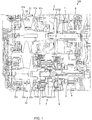
- FIG. 1 is a schematic construction diagram of an automatic transmission according to a first embodiment of the present invention
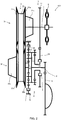
- FIG. 2 is a skeleton diagram of the automatic transmission according to the first embodiment of the present invention
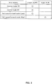
- FIG. 3 is a table showing engaged states of a clutch and a brake
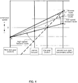
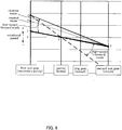
- FIG. 4 is a speed diagram (alignment chart) of a planetary gear mechanism in the first embodiment
- FIG. 5 is a skeleton diagram of an automatic transmission according to a second embodiment of the present invention.
- FIG. 6 is a speed diagram (alignment chart) of a planetary gear mechanism in the second embodiment.
- FIG. 1 is a schematic construction diagram showing the construction of an automatic transmission 100 according to this embodiment.
- FIG. 2 is a skeleton diagram schematically showing the construction of the automatic transmission 100.
- the automatic transmission 100 includes an input shaft 1, an output shaft 2, a continuously variable transmission mechanism 3, a planetary gear mechanism 4, a coupling member 5, a clutch 6 and a brake 7.
- the input shaft 1 is coupled to a primary pulley 31 of the continuously variable transmission mechanism 3 to transmit a torque input from a drive source such as an engine via a torque converter 8 to the continuously variable transmission mechanism 3.
- the output shaft 2 transmits a drive force varied in its amount and combined in the continuously variable transmission mechanism 3 and the planetary gear mechanism 4 to drive wheels of a vehicle via a differential gear 9.
- the continuously variable transmission mechanism 3 includes a primary pulley 31 as an input unit, a secondary pulley 32 as an output unit and a belt 33.
- the primary pulley 31 is an input shaft side pulley for inputting rotation of the drive source to the continuously variable transmission mechanism 3.
- the primary pulley 31 includes a fixed conical plate 31b and a movable conical plate 31a.
- the fixed conical plate 31b rotates together with the input shaft 1.
- the movable conical plate 31a is arranged to face the fixed conical plate 31 b and form a V-shaped pulley groove, and is displaceable in an axial direction by hydraulic pressure acting on a primary pulley cylinder chamber 31c.
- the primary pulley cylinder chamber 31c is arranged on an input shaft side (right side in FIG. 1 ) of the primary pulley 31.
- the belt 33 is mounted between the primary pulley 31 and the secondary pulley 32 and transmits the rotation of the primary pulley 31 to the secondary pulley 32.
- the belt 33 may be a V-belt formed by connecting a multitude of elements by a band-like belt or may be a chain belt formed by connecting a multitude of blocks in a band-like manner by links and pins.
- the secondary pulley 32 is an output shaft side pulley for outputting the rotation transmitted by the belt 33.
- the secondary pulley 32 includes a fixed conical plate 32b and a movable conical plate 32a.
- the fixed conical plate 32b rotates together with the output shaft 2.
- the movable conical plate 32a is arranged to face the fixed conical plate 32b and form a V-shaped pulley groove, and is displaceable in an axial direction according to hydraulic pressure acting on a secondary pulley cylinder chamber 32c.
- the secondary pulley cylinder chamber 32c is arranged on a side (left side in FIG. 1 ) opposite to the output shaft side of the secondary pulley 32.
- the planetary gear mechanism 4 is a Ravigneaux planetary gear mechanism 4 and includes a first sun gear 41, a second sun gear 42, a carrier 45 and a ring gear 46.
- the second sun gear 42 is coupled to the secondary pulley 32 of the continuously variable transmission mechanism 3.
- the carrier 45 supports a short pinion gear 43 engaged with the second sun gear 42 and a long pinion gear 44 engaged with the short pinion gear 43.
- the ring gear 46 is engaged with the long pinion gear 44.
- the coupling member 5 includes a first coupling gear 51 coupled to the input shaft 1 and a second coupling gear 52 engaged with the first coupling gear 51.
- the coupling member 5 changes the rotational speed of the input shaft 1 according to a gear ratio (constant value) of the first coupling gear 51 to the second coupling gear 52 and transmits the rotation of the input shaft 1 to the first sun gear 41.
- the gear ratio of the first coupling gear 51 to the second coupling gear 52 is described later.
- the clutch 6 is an engagement element provided radially inwardly of the second coupling gear 52 and capable of switching an engaged state of the first coupling gear 41 and the second coupling gear 52.
- the brake 7 is a friction element fixed to a transmission case 10 and capable of locking the rotation of the ring gear 46.
- FIG. 3 is a table showing a relationship between drive modes and engaged states of the clutch 6 and the brake 7.
- the automatic transmission 100 has four modes, i.e. a reverse mode, a neutral mode, a low-speed forward mode and a high-speed forward mode.
- the reverse mode is set in the case of reverse drive.
- the neutral mode is set when the vehicle is stopped.
- the low-speed forward mode is set in the case of forward drive at a low speed.
- the high-speed forward mode is set in the case of forward drive at a high speed.
- FIG. 4 is a speed diagram showing a relationship between the four rotation elements of the planetary gear mechanism 4 and the rotational speeds of the respective elements.
- the planetary gear mechanism 4 is composed of the four rotation elements of the first sun gear 41, the carrier 45, the ring gear 46 and the second sun gear 42 shown from left in the speed diagram. Distances between the respective rotation elements (horizontal axis of FIG. 4 ) are specified according to gear ratios between the respective rotation elements.
- the first sun gear 41 constantly rotates in a direction opposite to the input shaft 1.
- the second sun gear 42 constantly rotates in the same direction as the input shaft 1.
- the rotational speed of the carrier 45 and the ring gear 46 are specified according to the rotational speed of the first sun gear 41 and that of the second sun gear 42.
- a line turns about a point A when the clutch 6 is engaged and the brake 7 is released.
- the rotational speed of the second sun gear 42 varies according to a speed ratio (a ratio of a rotation speed of the primary pulley 31 to a rotation speed of the secondary pulley 32) of the continuously variable transmission mechanism 3 and reaches a point D at a realizable maximum speed ratio while reaching a point B at a realizable minimum speed ratio. That is, the line turns from a line A-B to a line A-D.
- the gear ratio of the first coupling gear 51 to the second coupling gear 52 is so set in advance that the rotational speed of the carrier 45 coupled to the output shaft becomes positive (forward direction relative to the second sun gear 42) and negative (reverse direction relative to the second sun gear 42) while crossing zero when the line turns from the line A-B to the line A-D.
- the line turns about a point E when the clutch 6 is released and the brake 7 is engaged.
- the rotational speed of the second sun gear 42 varies between the points B and D according to the speed ratio of the continuously variable transmission mechanism 3 as described above. That is, the line turns from a line E-B to a line E-D.
- the rotational speed of the carrier 45 coupled to the output shaft 2 is constantly negative (reverse direction relative to the second sun gear 42) and increases in a negative direction as compared with the case where the clutch 6 is engaged.
- the clutch 6 When the drive mode is the reverse mode, the clutch 6 is engaged and the brake 7 is released.
- the first sun gear 41 is coupled to the second coupling gear 52 and the rotational speed of the first sun gear 41 is specified by the rotational speed of the input shaft 1.
- the speed ratio of the continuously variable transmission mechanism 3 is set to be higher than a predetermined intermediate speed ratio and the rotational speed of the second sun gear 42 increases.
- the predetermined intermediate speed ratio is set according to the rotational speed of the input shaft 1 so that the rotational speed of the carrier 45 is higher than zero.
- the rotational speed of the first sun gear 41 is at the point A and the rotational speed of the second sun gear 42 changes in the range of the point B to the point C according to the speed ratio of the continuously variable transmission mechanism.
- This causes a line segment to turn about the point A.
- the rotational speed of the carrier 45 is a value larger than 0, the output shaft 2 rotates in a direction to drive the vehicle backward.
- the reverse travel speed of the vehicle can be set at a desired speed by changing the speed ratio of the continuously variable transmission mechanism 3.
- the clutch 6 When the drive mode is the neutral mode, the clutch 6 is engaged and the brake 7 is released.
- the first sun gear 41 is engaged with the second coupling gear 52 and the rotational speed of the first sun gear 41 is specified by the rotational speed of the input shaft 1.
- the speed ratio of the continuously variable transmission mechanism 3 is set to the predetermined intermediate speed ratio. In this way, the rotational speed of the second sun gear 42 becomes lower than in the case of the reverse mode and the rotational speed of the carrier becomes zero.
- the rotational speed of the first sun gear 41 is at the point A
- the rotational speed of the second sun gear 42 is at the point C corresponding to the intermediate speed ratio of the continuously variable transmission mechanism 3, and the line segment stops in a state shown by dotted line (line A-C). Since the rotational speed of the carrier 45 becomes zero, the vehicle is kept in a stopped state. In this case, since the input shaft 1 is rotating, but the output shaft 2 is stopped, the speed ratio of the automatic transmission 100 as a whole is infinite.
- the clutch 6 When the drive mode is the low-speed forward mode, the clutch 6 is engaged and the brake 7 is released.
- the first sun gear 41 is engaged with the second coupling gear 52 and the rotational speed of the first sun gear 41 is specified by the rotational speed of the input shaft 1.
- the speed ratio of the continuously variable transmission mechanism 3 is set to be lower than the predetermined intermediate speed ratio.
- the rotational speed of the second sun gear 42 is further lower than in the case of the neutral mode.
- the rotational speed of the first sun gear 41 is at the point A and the rotational speed of the second sun gear 42 changes in the range of the point C to the point D. This causes the line segment to turn about the point A. Since the rotational speed of the carrier 45 is a value smaller than 0, the output shaft 2 rotates in a direction to drive the vehicle forward.
- the forward travel speed of the vehicle can be set at a desired speed by changing the speed ratio of the continuously variable transmission mechanism 3.
- the clutch 6 When the drive mode is the high-speed forward mode, the clutch 6 is released and the brake 7 is engaged. The rotation of the ring gear 46 is locked and the rotational speed thereof is kept at zero. The first sun gear 41 and the second coupling gear 52 are disengaged, and the first sun gear 41 rotates following the rotation of the long pinion gear 44. If the speed ratio of the continuously variable transmission mechanism 3 is changed to be higher in this state, the rotational speed of the second sun gear 42 increases.
- the line segment turns about the point E according to the rotational speed of the second sun gear from a state connecting the points A and D (line A-D).
- the rotational speed of the carrier 45 is reduced to be considerably lower than zero and the output shaft 2 rotates at a high speed in the direction to drive the vehicle forward.
- the forward travel speed of the vehicle can be set at a desired speed by changing the speed ratio of the continuously variable transmission mechanism 3.
- the reverse mode, the neutral mode and the low-speed forward mode can be switched only by changing the speed ratio of the continuously variable transmission mechanism 3 without changing the engaged states of the clutch 6 and the brake 7.
- a switch between the low-speed forward mode and the high-speed forward mode is made by switching the engaged states of the clutch 6 and the brake 7.
- the switch between the low-speed forward mode and the high-speed forward mode is made at a predetermined mode switch speed ratio (e.g. maximum speed ratio).
- the gear ratio between the first and second coupling gears 51, 52 is so set in advance that the rotational speed of the input shaft 1 is equal regardless of whether the low-speed forward mode or the high-speed forward mode is set when the speed ratio of the continuously variable transmission mechanism 3 is set at the predetermined mode switch speed ratio.
- the rotation direction of the output shaft 2 can be changed from the forward direction to the reverse direction relative to the second sun gear 42 by setting the clutch 6 in the engaged state and changing the speed ratio of the continuously variable transmission mechanism 3. Since the drive mode can be set to the reverse mode, the neutral mode and the low-speed forward mode in this way, forward and reverse drives can be enabled without providing a friction element exclusively used for reverse drive. Therefore, a cost increase and enlargement of the transmission can be suppressed.
- the gear ratio of the coupling member 5 is so set that the rotational speed of the first sun gear 41 in the low-speed forward mode and that of the first sun gear 41 in the high-speed forward mode are equal when the speed ratio of the continuously variable transmission mechanism 3 is set at the mode switch speed ratio. This can prevent the occurrence of a shock caused by a rotational speed difference when the switch is made between the low-speed forward mode and the high-speed forward mode.
- the mode switch speed ratio is set at the maximum speed ratio of the continuously variable transmission mechanism 3
- the switch between the low-speed forward mode and the high-speed forward mode can be made at a lower speed as compared with the case where the mode switch speed ratio is not set at the maximum speed ratio. Further, a possible speed ratio range of the automatic transmission 100 can be increased.
- the axial length of the entire automatic transmission 100 can be shortened. Further, since the secondary pulley 32 and the coupling member 5 are respectively coupled to the two sun gears 41, 42 of the planetary gear mechanism 4 from the outside of the planetary gear mechanism 4, the axial length of the entire automatic transmission 100 can be further shortened.
- This embodiment differs from the first embodiment only in the structure of a planetary gear mechanism 80 and the relationship between the drive modes shown in FIG. 3 and the engaged states of the clutch 6 and the brake 7 is same.
- FIG. 5 is a skeleton diagram schematically showing the construction of an automatic transmission 200 in this embodiment.
- the planetary gear mechanism 80 of this embodiment is a Ravigneaux planetary gear mechanism and includes a first sun gear 81, a ring gear 82, a carrier 85 and a second sun gear 86.
- the first sun gear 81 is coupled to a secondary pulley 32.
- the ring gear 82 is coupled to an output shaft 2.
- the carrier 85 supports a long pinion gear 83 engaged with the first sun gear 81 and the ring gear 82 and a short pinion gear 84 engaged with the long pinion gear 83.
- the second sun gear 86 is engaged with the short pinion gear 84.
- a coupling member 5 includes a first coupling gear 51 coupled to an input shaft 1 and a second coupling gear 52 engaged with the first coupling gear 51.
- the coupling member 5 changes the rotational speed of the input shaft 1 according to a gear ratio (constant value) of the first coupling gear 51 to the second coupling gear 52 and transmits the rotation of the input shaft 1 to the second sun gear 86.
- the gear ratio of the first coupling gear 51 to the second coupling gear 52 is described later.
- a clutch 6 is an engagement element provided radially inwardly of the second coupling gear 52 and capable of switching an engaged state of the second sun gear 86 and the second coupling gear 52.
- a brake 7 is a friction element fixed to a transmission case 10 and capable of locking the rotation of the carrier 85.
- FIG. 6 is a speed diagram showing a relationship between the four rotation elements of the planetary gear mechanism 80 and the rotational speeds of the respective elements.
- the planetary gear mechanism 80 of this embodiment is composed of the four rotation elements of the first sun gear 81, the carrier 85, the ring gear 82 and the second sun gear 86 shown from left in the speed diagram. Distances between the respective rotation elements (horizontal axis of FIG. 6 ) are specified according to gear ratios between the respective rotation elements.
- the first sun gear 81 constantly rotates in a forward direction relative to the input shaft 1. Since the rotation of the input shaft 1 is transmitted to the second sun gear 86 via the first and second coupling gears 51, 52, the second sun gear 86 constantly rotates in a reverse direction relative to the input shaft 1.
- the carrier 85 and the ring gear 82 are specified according to the rotational speed of the first sun gear 81 and that of the second sun gear 86.
- a line turns about a point F when the clutch 6 is engaged and the brake 7 is released.
- the rotational speed of the first sun gear 81 varies according to a speed ratio (a ratio of a rotation speed of the primary pulley 31 to a rotation speed of the secondary pulley 32) of a continuously variable transmission mechanism 3 and reaches a point I at a realizable maximum speed ratio while reaching a point G at a minimum speed ratio. That is, the line turns from a line F-G to a line F-I.
- the gear ratio of the first coupling gear 51 to the second coupling gear 52 is so set in advance that the rotational speed of the ring gear 82 coupled to the output shaft 2 becomes positive (forward direction relative to the first sun gear 81) and negative (reverse direction relative to the first sun gear 81) while crossing zero when the line turns from the line F-G to the line F-I.
- the line turns about a point J when the clutch 6 is released and the brake 7 is engaged.
- the rotational speed of the first sun gear 81 varies between the points G and I according to the speed ratio of the continuously variable transmission mechanism 3 as described above.
- the rotational speed of the ring gear 82 coupled to the output shaft 2 is constantly negative (reverse direction relative to the first sun gear 81) and increases in a negative direction as compared with the case where the clutch 6 is engaged.
- the speed ratio of the continuously variable transmission mechanism 3 is set to be higher than a predetermined intermediate speed ratio. In this way, the rotational speed of the first sun gear 81 increases.
- the predetermined intermediate speed ratio is set according to the rotational speed of the input shaft 1 so that the rotational speed of the ring gear 82 is higher than zero similar to the first embodiment.
- the rotational speed of the second sun gear 86 is at the point F and the rotational speed of the first sun gear 81 changes in the range of the point G to the point H according to the speed ratio of the continuously variable transmission mechanism 3.
- This causes a line segment to turn about the point F.
- the rotational speed of the ring gear 82 is a value larger than 0, the output shaft 2 rotates in a direction to drive the vehicle backward.
- the reverse travel speed of the vehicle can be set at a desired speed by changing the speed ratio of the continuously variable transmission mechanism 3.
- the clutch 6 When the drive mode is the neutral mode, the clutch 6 is engaged and the brake 7 is released.
- the second sun gear 86 is engaged with the second coupling gear 52 and the rotational speed of the second sun gear 86 is specified by the rotational speed of the input shaft 1.
- the speed ratio of the continuously variable transmission mechanism 3 is set to the predetermined intermediate speed ratio. In this way, the rotational speed of the first sun gear 81 becomes lower than in the case of the reverse mode.
- the rotational speed of the second sun gear 86 is at the point F
- the rotational speed of the first sun gear 81 is at the point H corresponding to the intermediate speed ratio of the continuously variable transmission mechanism 3
- the line segment stops in a state shown by dotted line (line F-H). Since the rotational speed of the ring gear 82 becomes zero, the vehicle can be kept in a stopped state. In this case, since the input shaft 1 is rotating, but the output shaft 2 is stopped, the speed ratio of the automatic transmission 200 as a whole is infinite.
- the clutch 6 When the drive mode is the low-speed forward mode, the clutch 6 is engaged and the brake 7 is released.
- the second sun gear 86 is engaged with the second coupling gear 52 and the rotational speed of the second sun gear 86 is specified by the rotational speed of the input shaft 1.
- the speed ratio of the continuously variable transmission mechanism 3 is set to be lower than the predetermined intermediate speed ratio. In this way, the rotational speed of the first sun gear 81 is reduced further than in the case of the neutral mode.
- the rotational speed of the second sun gear 86 is at the point F and the rotational speed of the first sun gear 81 changes in the range of the point H to the point I. This causes the line segment to turn about the point F. Since the rotational speed of the ring gear 82 is a value smaller than 0, the output shaft 2 rotates in a direction to drive the vehicle forward.
- the forward travel speed of the vehicle can be set at a desired speed by changing the speed ratio of the continuously variable transmission mechanism 3.
- the clutch 6 When the drive mode is the high-speed forward mode, the clutch 6 is released and the brake 7 is engaged. The rotation of the carrier 85 is locked and the rotational speed thereof is kept at zero. The second sun gear 86 and the second coupling gear 52 are disengaged, and the second sun gear 86 rotates following the rotation of the short pinion gear 84. If the speed ratio of the continuously variable transmission mechanism 3 is changed to be higher in this state, the rotational speed of the first sun gear 81 increases.
- the line segment turns about the point J according to the rotational speed of the first sun gear 81 from a state connecting the points F and I.
- the rotational speed of the ring gear 82 is reduced to be considerably lower than zero and the output shaft 2 rotates at a high speed in the direction to drive the vehicle forward.
- the forward travel speed of the vehicle can be set at a desired speed by changing the speed ratio of the continuously variable transmission mechanism 3.
- the reverse mode, the neutral mode and the low-speed forward mode can be switched only by changing the speed ratio of the continuously variable transmission mechanism 3 without changing the engaged states of the clutch 6 and the brake 7.
- a switch between the low-speed forward mode and the high-speed forward mode is made by switching the engaged states of the clutch 6 and the brake 7.
- the switch between the low-speed forward mode and the high-speed forward mode is made at a predetermined mode switch speed ratio (e.g. maximum speed ratio).
- a predetermined mode switch speed ratio e.g. maximum speed ratio.
- the gear ratio between the first and second coupling gears 51, 52 is so set in advance that the rotational speed of the input shaft 1 is same regardless of whether the low-speed forward mode or the high-speed forward mode is set when the speed ratio of the continuously variable transmission mechanism 3 is set at the predetermined mode switch speed ratio.
- the rotation direction of the output shaft 2 is changed from the forward direction to the reverse direction relative to the first sun gear 81 by setting the clutch 6 in the engaged state and changing the speed ratio of the continuously variable transmission mechanism 3.
- the drive mode can be set to the reverse mode, the neutral mode and the low-speed forward mode, and forward and reverse drives can be enabled without providing a friction element exclusively used for reverse drive.
- the gear ratio of the coupling member 5 is so set that the rotational speed of the second sun gear 86 in the low-speed forward mode and that of the second sun gear 86 in the high-speed forward mode are equal when the speed ratio of the continuously variable transmission mechanism 3 is set at the mode switch speed ratio. This can prevent the occurrence of a shock caused by a rotational speed difference when the switch is made between the low-speed forward mode and the high-speed forward mode.
- the mode switch speed ratio is set at the maximum speed ratio of the continuously variable transmission mechanism 3
- the switch between the low-speed forward mode and the high-speed forward mode can be made at a lower speed as compared with the case where the mode switch speed ratio is not set at the maximum speed ratio. Further, a possible speed ratio range of the automatic transmission 200 can be increased.
- continuously variable transmission mechanism 3 has been described taking a belt continuously variable transmission as an example in the first and second embodiments, it may be another continuously variable transmission mechanism if the speed ratio can be continuously changed.
- the mode switch speed ratio is set at the maximum speed ratio of the continuously variable transmission mechanism 3 in the first and second embodiments, a higher speed ratio may be set as the mode switch speed ratio.
- the coupling member 5 is structurally composed of the first and second coupling gears 51, 52 in the first and second embodiments, any structure in which input rotation to the primary pulley 31 and that to the planetary gear mechanism 4, 80 via the coupling member 5 are opposite may be employed and the coupling member 5 may be replaced, for example, by a chain or the like.
Landscapes
- Engineering & Computer Science (AREA)
- General Engineering & Computer Science (AREA)
- Mechanical Engineering (AREA)
- Transmission Devices (AREA)
- Structure Of Transmissions (AREA)
Abstract
Description
- The present invention relates to an automatic transmission with a continuously variable transmission mechanism and a planetary gear mechanism.
- An automatic transmission called an IVT (Infinite Variable Transmission) can infinitely change a speed ratio by combining a continuously variable transmission mechanism capable of continuously changing a speed ratio and a planetary gear mechanism.
-
JP1-169169A - Since the above automatic transmission needs to include the friction element exclusively provided for the reverse mode to realize the reverse mode, cost increases and the transmission becomes larger.
- An object of this invention is to enable reverse drive without providing a friction element exclusively used for reverse drive in an automatic transmission capable of infinitely changing a speed ratio.
- According to an aspect of the present invention, an automatic transmission which changes a rotational speed of an input shaft and transmits rotation of the input shaft to an output shaft is provided. The transmission comprises a continuously variable transmission mechanism which continuously changes a rotational speed ratio of an input unit to an output unit; a planetary gear mechanism including at least four rotation elements shown in the order of a first rotation element, a second rotation element, a third rotation element and a fourth rotation element on a speed diagram; a clutch which causes the input shaft and the first rotation element to be engaged; a coupling member which changes the rotational speed of the input shaft at a constant speed ratio and transmits the rotation of the input shaft to the first rotation element via the clutch; and a brake which locks rotation of the third rotation element.
- The input shaft is coupled to the input unit. The output shaft is coupled to the second rotation element. The output unit is coupled to the fourth rotation element. The constant speed ratio of the coupling member is so set that a rotation direction of the output shaft relative to the fourth rotation element changes from a forward direction to a reverse direction according to a change in the speed ratio of the continuously variable transmission mechanism when the clutch is engaged and the brake is released.
- According to the above aspect, the rotation direction of the output shaft can be changed from the forward direction to the reverse direction relative to the fourth rotation element by setting the clutch in the engaged state and changing the speed ratio of the continuously variable transmission mechanism. Thus, forward and reverse drives can be enabled without providing a friction element exclusively used for reverse drive.
- Embodiments and advantages of this invention will be described in detail below with reference to the attached figures.
-
FIG. 1 is a schematic construction diagram of an automatic transmission according to a first embodiment of the present invention, -
FIG. 2 is a skeleton diagram of the automatic transmission according to the first embodiment of the present invention, -
FIG. 3 is a table showing engaged states of a clutch and a brake, -
FIG. 4 is a speed diagram (alignment chart) of a planetary gear mechanism in the first embodiment, -
FIG. 5 is a skeleton diagram of an automatic transmission according to a second embodiment of the present invention. -
FIG. 6 is a speed diagram (alignment chart) of a planetary gear mechanism in the second embodiment. - First, a first embodiment is described.
-
FIG. 1 is a schematic construction diagram showing the construction of anautomatic transmission 100 according to this embodiment.FIG. 2 is a skeleton diagram schematically showing the construction of theautomatic transmission 100. - The
automatic transmission 100 includes aninput shaft 1, anoutput shaft 2, a continuouslyvariable transmission mechanism 3, aplanetary gear mechanism 4, acoupling member 5, aclutch 6 and abrake 7. - The
input shaft 1 is coupled to aprimary pulley 31 of the continuouslyvariable transmission mechanism 3 to transmit a torque input from a drive source such as an engine via atorque converter 8 to the continuouslyvariable transmission mechanism 3. - The
output shaft 2 transmits a drive force varied in its amount and combined in the continuouslyvariable transmission mechanism 3 and theplanetary gear mechanism 4 to drive wheels of a vehicle via adifferential gear 9. - The continuously
variable transmission mechanism 3 includes aprimary pulley 31 as an input unit, asecondary pulley 32 as an output unit and abelt 33. - The
primary pulley 31 is an input shaft side pulley for inputting rotation of the drive source to the continuouslyvariable transmission mechanism 3. Theprimary pulley 31 includes a fixedconical plate 31b and a movableconical plate 31a. The fixedconical plate 31b rotates together with theinput shaft 1. The movableconical plate 31a is arranged to face the fixedconical plate 31 b and form a V-shaped pulley groove, and is displaceable in an axial direction by hydraulic pressure acting on a primarypulley cylinder chamber 31c. The primarypulley cylinder chamber 31c is arranged on an input shaft side (right side inFIG. 1 ) of theprimary pulley 31. - The
belt 33 is mounted between theprimary pulley 31 and thesecondary pulley 32 and transmits the rotation of theprimary pulley 31 to thesecondary pulley 32. Thebelt 33 may be a V-belt formed by connecting a multitude of elements by a band-like belt or may be a chain belt formed by connecting a multitude of blocks in a band-like manner by links and pins. - The
secondary pulley 32 is an output shaft side pulley for outputting the rotation transmitted by thebelt 33. Thesecondary pulley 32 includes a fixedconical plate 32b and a movableconical plate 32a. The fixedconical plate 32b rotates together with theoutput shaft 2. The movableconical plate 32a is arranged to face the fixedconical plate 32b and form a V-shaped pulley groove, and is displaceable in an axial direction according to hydraulic pressure acting on a secondarypulley cylinder chamber 32c. The secondarypulley cylinder chamber 32c is arranged on a side (left side inFIG. 1 ) opposite to the output shaft side of thesecondary pulley 32. - The
planetary gear mechanism 4 is a Ravigneauxplanetary gear mechanism 4 and includes afirst sun gear 41, asecond sun gear 42, acarrier 45 and aring gear 46. Thesecond sun gear 42 is coupled to thesecondary pulley 32 of the continuouslyvariable transmission mechanism 3. Thecarrier 45 supports ashort pinion gear 43 engaged with thesecond sun gear 42 and along pinion gear 44 engaged with theshort pinion gear 43. Thering gear 46 is engaged with thelong pinion gear 44. - The
coupling member 5 includes afirst coupling gear 51 coupled to theinput shaft 1 and asecond coupling gear 52 engaged with thefirst coupling gear 51. Thecoupling member 5 changes the rotational speed of theinput shaft 1 according to a gear ratio (constant value) of thefirst coupling gear 51 to thesecond coupling gear 52 and transmits the rotation of theinput shaft 1 to thefirst sun gear 41. The gear ratio of thefirst coupling gear 51 to thesecond coupling gear 52 is described later. - The
clutch 6 is an engagement element provided radially inwardly of thesecond coupling gear 52 and capable of switching an engaged state of thefirst coupling gear 41 and thesecond coupling gear 52. - The
brake 7 is a friction element fixed to atransmission case 10 and capable of locking the rotation of thering gear 46. - Next, the operation of the
automatic transmission 100 is described. -
FIG. 3 is a table showing a relationship between drive modes and engaged states of theclutch 6 and thebrake 7. Theautomatic transmission 100 has four modes, i.e. a reverse mode, a neutral mode, a low-speed forward mode and a high-speed forward mode. The reverse mode is set in the case of reverse drive. The neutral mode is set when the vehicle is stopped. The low-speed forward mode is set in the case of forward drive at a low speed. The high-speed forward mode is set in the case of forward drive at a high speed. - When the
clutch 6 is engaged and thebrake 7 is released, the reverse mode, the neutral mode and the low-speed forward mode are realized. When thebrake 7 is engaged and theclutch 6 is released, the high-speed forward mode is realized. -
FIG. 4 is a speed diagram showing a relationship between the four rotation elements of theplanetary gear mechanism 4 and the rotational speeds of the respective elements. Theplanetary gear mechanism 4 is composed of the four rotation elements of thefirst sun gear 41, thecarrier 45, thering gear 46 and thesecond sun gear 42 shown from left in the speed diagram. Distances between the respective rotation elements (horizontal axis ofFIG. 4 ) are specified according to gear ratios between the respective rotation elements. - Since the rotation of the
input shaft 1 is transmitted to thefirst sun gear 41 via the first and second coupling gears 51, 52, thefirst sun gear 41 constantly rotates in a direction opposite to theinput shaft 1. Since being coupled to thesecondary pulley 32, thesecond sun gear 42 constantly rotates in the same direction as theinput shaft 1. The rotational speed of thecarrier 45 and thering gear 46 are specified according to the rotational speed of thefirst sun gear 41 and that of thesecond sun gear 42. - As shown in
FIG. 4 , a line turns about a point A when theclutch 6 is engaged and thebrake 7 is released. The rotational speed of thesecond sun gear 42 varies according to a speed ratio (a ratio of a rotation speed of theprimary pulley 31 to a rotation speed of the secondary pulley 32) of the continuouslyvariable transmission mechanism 3 and reaches a point D at a realizable maximum speed ratio while reaching a point B at a realizable minimum speed ratio. That is, the line turns from a line A-B to a line A-D. - The gear ratio of the
first coupling gear 51 to thesecond coupling gear 52 is so set in advance that the rotational speed of thecarrier 45 coupled to the output shaft becomes positive (forward direction relative to the second sun gear 42) and negative (reverse direction relative to the second sun gear 42) while crossing zero when the line turns from the line A-B to the line A-D. - On the other hand, the line turns about a point E when the
clutch 6 is released and thebrake 7 is engaged. The rotational speed of thesecond sun gear 42 varies between the points B and D according to the speed ratio of the continuouslyvariable transmission mechanism 3 as described above. That is, the line turns from a line E-B to a line E-D. - In this case, the rotational speed of the
carrier 45 coupled to theoutput shaft 2 is constantly negative (reverse direction relative to the second sun gear 42) and increases in a negative direction as compared with the case where theclutch 6 is engaged. - The respective drive modes are described below.
- When the drive mode is the reverse mode, the
clutch 6 is engaged and thebrake 7 is released. Thefirst sun gear 41 is coupled to thesecond coupling gear 52 and the rotational speed of thefirst sun gear 41 is specified by the rotational speed of theinput shaft 1. The speed ratio of the continuouslyvariable transmission mechanism 3 is set to be higher than a predetermined intermediate speed ratio and the rotational speed of thesecond sun gear 42 increases. The predetermined intermediate speed ratio is set according to the rotational speed of theinput shaft 1 so that the rotational speed of thecarrier 45 is higher than zero. - As shown in the speed diagram of
FIG. 4 , the rotational speed of thefirst sun gear 41 is at the point A and the rotational speed of thesecond sun gear 42 changes in the range of the point B to the point C according to the speed ratio of the continuously variable transmission mechanism. This causes a line segment to turn about the point A. Since the rotational speed of thecarrier 45 is a value larger than 0, theoutput shaft 2 rotates in a direction to drive the vehicle backward. The reverse travel speed of the vehicle can be set at a desired speed by changing the speed ratio of the continuouslyvariable transmission mechanism 3. - When the drive mode is the neutral mode, the
clutch 6 is engaged and thebrake 7 is released. Thefirst sun gear 41 is engaged with thesecond coupling gear 52 and the rotational speed of thefirst sun gear 41 is specified by the rotational speed of theinput shaft 1. The speed ratio of the continuouslyvariable transmission mechanism 3 is set to the predetermined intermediate speed ratio. In this way, the rotational speed of thesecond sun gear 42 becomes lower than in the case of the reverse mode and the rotational speed of the carrier becomes zero. - As shown in the speed diagram of
FIG. 4 , the rotational speed of thefirst sun gear 41 is at the point A, the rotational speed of thesecond sun gear 42 is at the point C corresponding to the intermediate speed ratio of the continuouslyvariable transmission mechanism 3, and the line segment stops in a state shown by dotted line (line A-C). Since the rotational speed of thecarrier 45 becomes zero, the vehicle is kept in a stopped state. In this case, since theinput shaft 1 is rotating, but theoutput shaft 2 is stopped, the speed ratio of theautomatic transmission 100 as a whole is infinite. - When the drive mode is the low-speed forward mode, the
clutch 6 is engaged and thebrake 7 is released. Thefirst sun gear 41 is engaged with thesecond coupling gear 52 and the rotational speed of thefirst sun gear 41 is specified by the rotational speed of theinput shaft 1. The speed ratio of the continuouslyvariable transmission mechanism 3 is set to be lower than the predetermined intermediate speed ratio. The rotational speed of thesecond sun gear 42 is further lower than in the case of the neutral mode. - As shown in the speed diagram of
FIG. 4 , the rotational speed of thefirst sun gear 41 is at the point A and the rotational speed of thesecond sun gear 42 changes in the range of the point C to the point D. This causes the line segment to turn about the point A. Since the rotational speed of thecarrier 45 is a value smaller than 0, theoutput shaft 2 rotates in a direction to drive the vehicle forward. The forward travel speed of the vehicle can be set at a desired speed by changing the speed ratio of the continuouslyvariable transmission mechanism 3. - When the drive mode is the high-speed forward mode, the
clutch 6 is released and thebrake 7 is engaged. The rotation of thering gear 46 is locked and the rotational speed thereof is kept at zero. Thefirst sun gear 41 and thesecond coupling gear 52 are disengaged, and thefirst sun gear 41 rotates following the rotation of thelong pinion gear 44. If the speed ratio of the continuouslyvariable transmission mechanism 3 is changed to be higher in this state, the rotational speed of thesecond sun gear 42 increases. - As shown in the speed diagram of
FIG. 4 , the line segment turns about the point E according to the rotational speed of the second sun gear from a state connecting the points A and D (line A-D). The rotational speed of thecarrier 45 is reduced to be considerably lower than zero and theoutput shaft 2 rotates at a high speed in the direction to drive the vehicle forward. The forward travel speed of the vehicle can be set at a desired speed by changing the speed ratio of the continuouslyvariable transmission mechanism 3. - Out of the above drive modes, the reverse mode, the neutral mode and the low-speed forward mode can be switched only by changing the speed ratio of the continuously
variable transmission mechanism 3 without changing the engaged states of theclutch 6 and thebrake 7. On the other hand, a switch between the low-speed forward mode and the high-speed forward mode is made by switching the engaged states of theclutch 6 and thebrake 7. - The switch between the low-speed forward mode and the high-speed forward mode is made at a predetermined mode switch speed ratio (e.g. maximum speed ratio). The gear ratio between the first and second coupling gears 51, 52 is so set in advance that the rotational speed of the
input shaft 1 is equal regardless of whether the low-speed forward mode or the high-speed forward mode is set when the speed ratio of the continuouslyvariable transmission mechanism 3 is set at the predetermined mode switch speed ratio. - This can prevent the occurrence of a shock caused by a rotational speed difference when the mode is switched between the low-speed forward mode and the high-speed forward mode and the engaged states of the clutch and the brake are switched. Thus, the drive modes can be smoothly switched.
- In this embodiment, the rotation direction of the
output shaft 2 can be changed from the forward direction to the reverse direction relative to thesecond sun gear 42 by setting the clutch 6 in the engaged state and changing the speed ratio of the continuouslyvariable transmission mechanism 3. Since the drive mode can be set to the reverse mode, the neutral mode and the low-speed forward mode in this way, forward and reverse drives can be enabled without providing a friction element exclusively used for reverse drive. Therefore, a cost increase and enlargement of the transmission can be suppressed. - The gear ratio of the
coupling member 5 is so set that the rotational speed of thefirst sun gear 41 in the low-speed forward mode and that of thefirst sun gear 41 in the high-speed forward mode are equal when the speed ratio of the continuouslyvariable transmission mechanism 3 is set at the mode switch speed ratio. This can prevent the occurrence of a shock caused by a rotational speed difference when the switch is made between the low-speed forward mode and the high-speed forward mode. - Since the mode switch speed ratio is set at the maximum speed ratio of the continuously
variable transmission mechanism 3, the switch between the low-speed forward mode and the high-speed forward mode can be made at a lower speed as compared with the case where the mode switch speed ratio is not set at the maximum speed ratio. Further, a possible speed ratio range of theautomatic transmission 100 can be increased. - Since the
hydraulic chamber 31c of theprimary pulley 31 is provided on a side of theplanetary gear mechanism 4 and thehydraulic chamber 32c of thesecondary pulley 32 is provided on a side opposite to theplanetary gear mechanism 4, the axial length of the entireautomatic transmission 100 can be shortened. Further, since thesecondary pulley 32 and thecoupling member 5 are respectively coupled to the two sun gears 41, 42 of theplanetary gear mechanism 4 from the outside of theplanetary gear mechanism 4, the axial length of the entireautomatic transmission 100 can be further shortened. - Next, a second embodiment is described.
- This embodiment differs from the first embodiment only in the structure of a
planetary gear mechanism 80 and the relationship between the drive modes shown inFIG. 3 and the engaged states of theclutch 6 and thebrake 7 is same. -
FIG. 5 is a skeleton diagram schematically showing the construction of anautomatic transmission 200 in this embodiment. - The
planetary gear mechanism 80 of this embodiment is a Ravigneaux planetary gear mechanism and includes afirst sun gear 81, aring gear 82, acarrier 85 and asecond sun gear 86. Thefirst sun gear 81 is coupled to asecondary pulley 32. Thering gear 82 is coupled to anoutput shaft 2. Thecarrier 85 supports along pinion gear 83 engaged with thefirst sun gear 81 and thering gear 82 and ashort pinion gear 84 engaged with thelong pinion gear 83. Thesecond sun gear 86 is engaged with theshort pinion gear 84. - A
coupling member 5 includes afirst coupling gear 51 coupled to aninput shaft 1 and asecond coupling gear 52 engaged with thefirst coupling gear 51. Thecoupling member 5 changes the rotational speed of theinput shaft 1 according to a gear ratio (constant value) of thefirst coupling gear 51 to thesecond coupling gear 52 and transmits the rotation of theinput shaft 1 to thesecond sun gear 86. The gear ratio of thefirst coupling gear 51 to thesecond coupling gear 52 is described later. - A
clutch 6 is an engagement element provided radially inwardly of thesecond coupling gear 52 and capable of switching an engaged state of thesecond sun gear 86 and thesecond coupling gear 52. - A
brake 7 is a friction element fixed to atransmission case 10 and capable of locking the rotation of thecarrier 85. - Next, the operation of the
automatic transmission 200 is described. -
FIG. 6 is a speed diagram showing a relationship between the four rotation elements of theplanetary gear mechanism 80 and the rotational speeds of the respective elements. Theplanetary gear mechanism 80 of this embodiment is composed of the four rotation elements of thefirst sun gear 81, thecarrier 85, thering gear 82 and thesecond sun gear 86 shown from left in the speed diagram. Distances between the respective rotation elements (horizontal axis ofFIG. 6 ) are specified according to gear ratios between the respective rotation elements. - Since being coupled to the
secondary pulley 32, thefirst sun gear 81 constantly rotates in a forward direction relative to theinput shaft 1. Since the rotation of theinput shaft 1 is transmitted to thesecond sun gear 86 via the first and second coupling gears 51, 52, thesecond sun gear 86 constantly rotates in a reverse direction relative to theinput shaft 1. Thecarrier 85 and thering gear 82 are specified according to the rotational speed of thefirst sun gear 81 and that of thesecond sun gear 86. - As shown in
FIG. 6 , a line turns about a point F when theclutch 6 is engaged and thebrake 7 is released. The rotational speed of thefirst sun gear 81 varies according to a speed ratio (a ratio of a rotation speed of theprimary pulley 31 to a rotation speed of the secondary pulley 32) of a continuouslyvariable transmission mechanism 3 and reaches a point I at a realizable maximum speed ratio while reaching a point G at a minimum speed ratio. That is, the line turns from a line F-G to a line F-I. - The gear ratio of the
first coupling gear 51 to thesecond coupling gear 52 is so set in advance that the rotational speed of thering gear 82 coupled to theoutput shaft 2 becomes positive (forward direction relative to the first sun gear 81) and negative (reverse direction relative to the first sun gear 81) while crossing zero when the line turns from the line F-G to the line F-I. - On the other hand, the line turns about a point J when the
clutch 6 is released and thebrake 7 is engaged. The rotational speed of thefirst sun gear 81 varies between the points G and I according to the speed ratio of the continuouslyvariable transmission mechanism 3 as described above. In this case, the rotational speed of thering gear 82 coupled to theoutput shaft 2 is constantly negative (reverse direction relative to the first sun gear 81) and increases in a negative direction as compared with the case where theclutch 6 is engaged. - The respective drive modes are described below.
- When the drive mode is the reverse mode, the
clutch 6 is engaged and thebrake 7 is released. Thesecond sun gear 86 is coupled to thesecond coupling gear 52 and the rotational speed of thesecond sun gear 86 is specified by the rotational speed of theinput shaft 1. The speed ratio of the continuouslyvariable transmission mechanism 3 is set to be higher than a predetermined intermediate speed ratio. In this way, the rotational speed of thefirst sun gear 81 increases. The predetermined intermediate speed ratio is set according to the rotational speed of theinput shaft 1 so that the rotational speed of thering gear 82 is higher than zero similar to the first embodiment. - As shown in the speed diagram of
FIG. 6 , the rotational speed of thesecond sun gear 86 is at the point F and the rotational speed of thefirst sun gear 81 changes in the range of the point G to the point H according to the speed ratio of the continuouslyvariable transmission mechanism 3. This causes a line segment to turn about the point F. Since the rotational speed of thering gear 82 is a value larger than 0, theoutput shaft 2 rotates in a direction to drive the vehicle backward. The reverse travel speed of the vehicle can be set at a desired speed by changing the speed ratio of the continuouslyvariable transmission mechanism 3. - When the drive mode is the neutral mode, the
clutch 6 is engaged and thebrake 7 is released. Thesecond sun gear 86 is engaged with thesecond coupling gear 52 and the rotational speed of thesecond sun gear 86 is specified by the rotational speed of theinput shaft 1. The speed ratio of the continuouslyvariable transmission mechanism 3 is set to the predetermined intermediate speed ratio. In this way, the rotational speed of thefirst sun gear 81 becomes lower than in the case of the reverse mode. - As shown in the speed diagram of
FIG. 6 , the rotational speed of thesecond sun gear 86 is at the point F, the rotational speed of thefirst sun gear 81 is at the point H corresponding to the intermediate speed ratio of the continuouslyvariable transmission mechanism 3, and the line segment stops in a state shown by dotted line (line F-H). Since the rotational speed of thering gear 82 becomes zero, the vehicle can be kept in a stopped state. In this case, since theinput shaft 1 is rotating, but theoutput shaft 2 is stopped, the speed ratio of theautomatic transmission 200 as a whole is infinite. - When the drive mode is the low-speed forward mode, the
clutch 6 is engaged and thebrake 7 is released. Thesecond sun gear 86 is engaged with thesecond coupling gear 52 and the rotational speed of thesecond sun gear 86 is specified by the rotational speed of theinput shaft 1. The speed ratio of the continuouslyvariable transmission mechanism 3 is set to be lower than the predetermined intermediate speed ratio. In this way, the rotational speed of thefirst sun gear 81 is reduced further than in the case of the neutral mode. - As shown in the speed diagram of
FIG. 6 , the rotational speed of thesecond sun gear 86 is at the point F and the rotational speed of thefirst sun gear 81 changes in the range of the point H to the point I. This causes the line segment to turn about the point F. Since the rotational speed of thering gear 82 is a value smaller than 0, theoutput shaft 2 rotates in a direction to drive the vehicle forward. The forward travel speed of the vehicle can be set at a desired speed by changing the speed ratio of the continuouslyvariable transmission mechanism 3. - When the drive mode is the high-speed forward mode, the
clutch 6 is released and thebrake 7 is engaged. The rotation of thecarrier 85 is locked and the rotational speed thereof is kept at zero. Thesecond sun gear 86 and thesecond coupling gear 52 are disengaged, and thesecond sun gear 86 rotates following the rotation of theshort pinion gear 84. If the speed ratio of the continuouslyvariable transmission mechanism 3 is changed to be higher in this state, the rotational speed of thefirst sun gear 81 increases. - As shown in the speed diagram of
FIG. 6 , the line segment turns about the point J according to the rotational speed of thefirst sun gear 81 from a state connecting the points F and I. The rotational speed of thering gear 82 is reduced to be considerably lower than zero and theoutput shaft 2 rotates at a high speed in the direction to drive the vehicle forward. The forward travel speed of the vehicle can be set at a desired speed by changing the speed ratio of the continuouslyvariable transmission mechanism 3. - Out of the above drive modes, the reverse mode, the neutral mode and the low-speed forward mode can be switched only by changing the speed ratio of the continuously
variable transmission mechanism 3 without changing the engaged states of theclutch 6 and thebrake 7. On the other hand, a switch between the low-speed forward mode and the high-speed forward mode is made by switching the engaged states of theclutch 6 and thebrake 7. - Similar to the first embodiment, the switch between the low-speed forward mode and the high-speed forward mode is made at a predetermined mode switch speed ratio (e.g. maximum speed ratio). The gear ratio between the first and second coupling gears 51, 52 is so set in advance that the rotational speed of the
input shaft 1 is same regardless of whether the low-speed forward mode or the high-speed forward mode is set when the speed ratio of the continuouslyvariable transmission mechanism 3 is set at the predetermined mode switch speed ratio. - In this embodiment, the rotation direction of the
output shaft 2 is changed from the forward direction to the reverse direction relative to thefirst sun gear 81 by setting the clutch 6 in the engaged state and changing the speed ratio of the continuouslyvariable transmission mechanism 3. In this way, the drive mode can be set to the reverse mode, the neutral mode and the low-speed forward mode, and forward and reverse drives can be enabled without providing a friction element exclusively used for reverse drive. - The gear ratio of the
coupling member 5 is so set that the rotational speed of thesecond sun gear 86 in the low-speed forward mode and that of thesecond sun gear 86 in the high-speed forward mode are equal when the speed ratio of the continuouslyvariable transmission mechanism 3 is set at the mode switch speed ratio. This can prevent the occurrence of a shock caused by a rotational speed difference when the switch is made between the low-speed forward mode and the high-speed forward mode. - Since the mode switch speed ratio is set at the maximum speed ratio of the continuously
variable transmission mechanism 3, the switch between the low-speed forward mode and the high-speed forward mode can be made at a lower speed as compared with the case where the mode switch speed ratio is not set at the maximum speed ratio. Further, a possible speed ratio range of theautomatic transmission 200 can be increased. - An embodiment of this invention was described above, but the above embodiment merely illustrates one example of application of the invention, and the technical scope of the invention is not limited to the specific constitutions of the above embodiment.
- For example, although the continuously
variable transmission mechanism 3 has been described taking a belt continuously variable transmission as an example in the first and second embodiments, it may be another continuously variable transmission mechanism if the speed ratio can be continuously changed. - Although the mode switch speed ratio is set at the maximum speed ratio of the continuously
variable transmission mechanism 3 in the first and second embodiments, a higher speed ratio may be set as the mode switch speed ratio. - Although the
coupling member 5 is structurally composed of the first and second coupling gears 51, 52 in the first and second embodiments, any structure in which input rotation to theprimary pulley 31 and that to theplanetary gear mechanism coupling member 5 are opposite may be employed and thecoupling member 5 may be replaced, for example, by a chain or the like. - This application claims priority based on Japanese Patent Application No.
2011-67178
Claims (4)
- An automatic transmission (100, 200) which changes a rotational speed of an input shaft (1) and transmits rotation of the input shaft (1) to an output shaft (2), comprising:a continuously variable transmission mechanism (3) which continuously changes a rotational speed ratio of an input unit (31) to an output unit (32);a planetary gear mechanism (4) including at least four rotation elements shown in the order of a first rotation element (41, 86), a second rotation element (45, 82), a third rotation element (46, 85) and a fourth rotation element (42, 81) on a speed diagram;a clutch (6) which causes the input shaft (1) and the first rotation element (41, 86) to be engaged;a coupling member (5) which changes the rotational speed of the input shaft (1) at a constant speed ratio and transmits the rotation of the input shaft (1) to the first rotation element (41, 86) via the clutch (6); anda brake (7) which locks rotation of the third rotation element (46, 85),wherein the input shaft (1) is coupled to the input unit (31),the output shaft (2) is coupled to the second rotation element (45, 82),the output unit (32) is coupled to the fourth rotation element (42, 81), andthe constant speed ratio of the coupling member (5) is so set that a rotation direction of the output shaft (2) relative to the fourth rotation element (42, 81) changes from a forward direction to a reverse direction according to a change in the speed ratio of the continuously variable transmission mechanism (3) when the clutch (6) is engaged and the brake (7) is released.
- The automatic transmission (100, 200) as defined in Claim 1, wherein the constant speed ratio of the coupling member (5) is so set that the rotational speed of the first rotation element (41, 86) is equal in a first mode in which the clutch (6) is engaged, the brake (7) is released and the rotational speed of the output shaft (2) is changed according to the change in the speed ratio of the continuously variable transmission mechanism (3) and a second mode in which the clutch (6) is released, the brake (7) is engaged and the rotational speed of the output shaft (2) is changed according to the change in the speed ratio of the continuously variable transmission mechanism (3) when the speed ratio of the continuously variable transmission mechanism (3) is set at a predetermined mode switch speed ratio.
- The automatic transmission (100, 200) as defined in Claim 2, wherein the mode switch speed ratio is a highest speed ratio realizable by the continuously variable transmission mechanism (3).
- The automatic transmission (100) as defined in any one of Claims 1 to 3, wherein the continuously variable transmission mechanism (3) is a belt continuously variable transmission constructed such that a belt is mounted between a primary pulley (31) as the input unit and a secondary pulley (32) as the output unit and movable sheaves of the respective pulleys are displaced to change the speed ratio by controlling supply pressures to hydraulic chambers (31 c, 32c) of the respective pulleys;
the planetary gear mechanism (4) is a Ravigneaux planetary gear mechanism including a first sun gear (41) as the first rotation element, a second sun gear (42) as the fourth rotation element, a ring gear (46) as the third rotation element and a carrier (45) supporting a long pinion gear (44) engaged with the first sun gear (41) and the ring gear (46) and a short pinion gear (43) engaged with the second sun gear (42) and the long pinion gear (44) as the second rotation element;
the second sun gear (42) is coupled to the secondary pulley (32) on a continuously variable transmission mechanism (3) side of the planetary gear mechanism (4);
the input shaft (1) is coupled to the primary pulley (31) on a planetary gear mechanism (4) side of the primary pulley (31);
the first sun gear (41) is coupled to the input shaft (1) via the coupling member (5) on a side of the planetary gear mechanism (4) opposite to the continuously variable transmission mechanism (3) side;
the output shaft (2) is arranged radially inwardly of the first sun gear (41) and coupled to the carrier (45) between the first sun gear (41) and the second sun gear (42);
the hydraulic chamber (31c) of the primary pulley (31) is provided on the planetary gear mechanism (4) side of the primary pulley (31); and
the hydraulic chamber (32c) of the secondary pulley (32) is arranged on a side of the secondary pulley (32) opposite to a planetary gear mechanism (4) side.
Applications Claiming Priority (1)
| Application Number | Priority Date | Filing Date | Title |
|---|---|---|---|
| JP2011067178A JP5340336B2 (en) | 2011-03-25 | 2011-03-25 | Automatic transmission |
Publications (2)
| Publication Number | Publication Date |
|---|---|
| EP2503186A2 true EP2503186A2 (en) | 2012-09-26 |
| EP2503186A3 EP2503186A3 (en) | 2018-04-18 |
Family
ID=45654978
Family Applications (1)
| Application Number | Title | Priority Date | Filing Date |
|---|---|---|---|
| EP12000915.4A Withdrawn EP2503186A3 (en) | 2011-03-25 | 2012-02-13 | Automatic transmission |
Country Status (5)
| Country | Link |
|---|---|
| US (1) | US9194471B2 (en) |
| EP (1) | EP2503186A3 (en) |
| JP (1) | JP5340336B2 (en) |
| KR (1) | KR101309341B1 (en) |
| CN (1) | CN102691769B (en) |
Families Citing this family (12)
| Publication number | Priority date | Publication date | Assignee | Title |
|---|---|---|---|---|
| KR101429265B1 (en) * | 2012-12-27 | 2014-08-08 | 현대 파워텍 주식회사 | Continuously variable auto transmission |
| KR101459462B1 (en) * | 2013-05-28 | 2014-11-07 | 현대자동차 주식회사 | Continuously variable transmission for vehicles |
| JP6255586B2 (en) * | 2013-06-28 | 2018-01-10 | ダイハツ工業株式会社 | Continuously variable transmission for vehicle |
| US9239103B2 (en) | 2013-07-03 | 2016-01-19 | Gm Global Technology Operations, Llc | Continuously variable transmission with chain output |
| ES2535989B1 (en) * | 2013-11-18 | 2016-02-24 | Powertrack Internacional De Automoción S.L. | Continuous and reversible mechanical transmission system with power shunt |
| US9689481B2 (en) * | 2014-09-04 | 2017-06-27 | Gm Global Technology Operations, Llc | One mode continuously variable transmission with low loss configuration |
| KR20160035328A (en) * | 2014-09-23 | 2016-03-31 | 현대자동차주식회사 | Continuously variable transmission for vehicles |
| WO2016098685A1 (en) * | 2014-12-18 | 2016-06-23 | 本田技研工業株式会社 | Stepless transmission |
| JP2016151315A (en) * | 2015-02-17 | 2016-08-22 | アイシン・エィ・ダブリュ株式会社 | Automatic transmission |
| JP6366624B2 (en) * | 2016-02-29 | 2018-08-01 | ダイハツ工業株式会社 | Transmission case |
| DE102017219111B4 (en) * | 2017-10-25 | 2022-05-25 | Zf Friedrichshafen Ag | Power-split continuously variable transmission device |
| US11198356B2 (en) | 2019-04-11 | 2021-12-14 | Dana Heavy Vehicle Systems Group, Llc | Methods and systems for an electric drive arrangement |
Citations (1)
| Publication number | Priority date | Publication date | Assignee | Title |
|---|---|---|---|---|
| JP2011067178A (en) | 2009-09-28 | 2011-04-07 | Kobe Univ | Method and kit for differentiating whether or not cattle is japanese non-black cattle |
Family Cites Families (20)
| Publication number | Priority date | Publication date | Assignee | Title |
|---|---|---|---|---|
| GB1603633A (en) * | 1978-05-30 | 1981-11-25 | Reimers Piv Antrieb Kg W | Continuously variable transmissions |
| DE3124070A1 (en) * | 1981-06-11 | 1983-01-05 | Vauxhall Motors Ltd., Luton, Bedfordshire | Continuously variable transmission |
| JPS60116959A (en) * | 1983-11-28 | 1985-06-24 | Toyota Central Res & Dev Lab Inc | Continuously variable transmission for vehicles |
| JP2929592B2 (en) * | 1987-12-24 | 1999-08-03 | 日本精工株式会社 | Toroidal continuously variable transmission |
| US5092434A (en) * | 1991-01-30 | 1992-03-03 | Borg-Warner Automotive, Inc | Control strategies for a dual range infinitely variable transmission |
| EP0838613B1 (en) * | 1996-10-25 | 2002-08-14 | Aisin Aw Co., Ltd. | Infinitely variable transmission |
| JP4062809B2 (en) * | 1999-02-03 | 2008-03-19 | 日本精工株式会社 | Continuously variable transmission |
| JP3861599B2 (en) * | 2001-01-19 | 2006-12-20 | トヨタ自動車株式会社 | Control device for continuously variable transmission |
| JP2003014074A (en) * | 2001-07-03 | 2003-01-15 | Nissan Motor Co Ltd | Transmission ratio infinitely variable transmission |
| DE10302992A1 (en) * | 2002-02-07 | 2003-10-16 | Luk Lamellen & Kupplungsbau | Gear ratio regulation method for motor vehicle power-branched continuously variable transmission has variator regulating range traversed in opposite directions for different gear ratio ranges |
| DE10231516B3 (en) * | 2002-07-12 | 2004-02-05 | Audi Ag | Speed-change gearbox |
| JP4552376B2 (en) * | 2002-11-29 | 2010-09-29 | 株式会社エクォス・リサーチ | Infinite transmission |
| JP2006132595A (en) | 2004-11-02 | 2006-05-25 | Nissan Motor Co Ltd | Automatic transmission for vehicles |
| JP4483819B2 (en) * | 2005-04-28 | 2010-06-16 | 株式会社豊田中央研究所 | Power transmission system |
| JP2006322482A (en) * | 2005-05-17 | 2006-11-30 | Nsk Ltd | Continuously variable transmission |
| JP2006329338A (en) * | 2005-05-26 | 2006-12-07 | Nissan Motor Co Ltd | Shunt-type continuously variable transmission |
| JP2007255561A (en) * | 2006-03-23 | 2007-10-04 | Nsk Ltd | Continuously variable transmission |
| DE112007003315A5 (en) | 2007-02-26 | 2009-11-05 | GIF Gesellschaft für Industrieforschung mbH | Drive arrangement with a continuously variable partial transmission |
| CN101649895B (en) | 2009-09-07 | 2012-08-22 | 郭克亚 | Hybrid continuously variable transmission |
| KR20110097196A (en) * | 2010-02-25 | 2011-08-31 | 현대 파워텍 주식회사 | Continuously variable transmission |
-
2011
- 2011-03-25 JP JP2011067178A patent/JP5340336B2/en not_active Expired - Fee Related
-
2012
- 2012-02-13 EP EP12000915.4A patent/EP2503186A3/en not_active Withdrawn
- 2012-02-16 US US13/398,202 patent/US9194471B2/en not_active Expired - Fee Related
- 2012-03-15 CN CN201210068404.5A patent/CN102691769B/en not_active Expired - Fee Related
- 2012-03-22 KR KR1020120029389A patent/KR101309341B1/en not_active Expired - Fee Related
Patent Citations (1)
| Publication number | Priority date | Publication date | Assignee | Title |
|---|---|---|---|---|
| JP2011067178A (en) | 2009-09-28 | 2011-04-07 | Kobe Univ | Method and kit for differentiating whether or not cattle is japanese non-black cattle |
Also Published As
| Publication number | Publication date |
|---|---|
| JP2012202473A (en) | 2012-10-22 |
| US20120244985A1 (en) | 2012-09-27 |
| JP5340336B2 (en) | 2013-11-13 |
| KR20120109366A (en) | 2012-10-08 |
| CN102691769B (en) | 2015-06-17 |
| EP2503186A3 (en) | 2018-04-18 |
| CN102691769A (en) | 2012-09-26 |
| KR101309341B1 (en) | 2013-09-17 |
| US9194471B2 (en) | 2015-11-24 |
Similar Documents
| Publication | Publication Date | Title |
|---|---|---|
| US9194471B2 (en) | Automatic transmission | |
| US10118478B2 (en) | Automatic transmission | |
| RU2307272C2 (en) | System of transmission with constantly changing gear ratio | |
| JP4983301B2 (en) | Transmission | |
| CN104334924A (en) | Continuously variable transmission | |
| US20160186846A1 (en) | Power transmission switching mechanism and transmission | |
| CN105723121A (en) | Power-split continuously variable transmission apparatus having summing planetary transmission | |
| CA2544938A1 (en) | Continuously variable ratio transmission | |
| US10352420B2 (en) | Continuously variable transmission | |
| KR101459462B1 (en) | Continuously variable transmission for vehicles | |
| JP2007091139A (en) | Variable speed transmission | |
| JP2010159883A (en) | Variable-speed transmission | |
| JP2017155841A (en) | Gear change device | |
| US10309506B2 (en) | Multiple-mode continuously variable transmission | |
| JP5946484B2 (en) | Continuously variable transmission | |
| RU2238457C2 (en) | Hydromechanical transmission | |
| JP5790575B2 (en) | transmission | |
| JP2016080108A (en) | transmission | |
| JP6123733B2 (en) | Vehicle transmission | |
| US10502268B2 (en) | Drivetrain provided with a CVT | |
| JP6365246B2 (en) | Automatic transmission | |
| JP2016188690A (en) | Automatic transmission | |
| JP5686343B2 (en) | Continuously variable transmission for vehicle | |
| CN105333082A (en) | Novel stepless speed change device | |
| JP2016164419A (en) | Automatic transmission |
Legal Events
| Date | Code | Title | Description |
|---|---|---|---|
| PUAI | Public reference made under article 153(3) epc to a published international application that has entered the european phase |
Free format text: ORIGINAL CODE: 0009012 |
|
| AK | Designated contracting states |
Kind code of ref document: A2 Designated state(s): AL AT BE BG CH CY CZ DE DK EE ES FI FR GB GR HR HU IE IS IT LI LT LU LV MC MK MT NL NO PL PT RO RS SE SI SK SM TR |
|
| AX | Request for extension of the european patent |
Extension state: BA ME |
|
| PUAL | Search report despatched |
Free format text: ORIGINAL CODE: 0009013 |
|
| AK | Designated contracting states |
Kind code of ref document: A3 Designated state(s): AL AT BE BG CH CY CZ DE DK EE ES FI FR GB GR HR HU IE IS IT LI LT LU LV MC MK MT NL NO PL PT RO RS SE SI SK SM TR |
|
| AX | Request for extension of the european patent |
Extension state: BA ME |
|
| RIC1 | Information provided on ipc code assigned before grant |
Ipc: F16H 37/02 20060101AFI20180314BHEP |
|
| 17P | Request for examination filed |
Effective date: 20180503 |
|
| RBV | Designated contracting states (corrected) |
Designated state(s): AL AT BE BG CH CY CZ DE DK EE ES FI FR GB GR HR HU IE IS IT LI LT LU LV MC MK MT NL NO PL PT RO RS SE SI SK SM TR |
|
| GRAP | Despatch of communication of intention to grant a patent |
Free format text: ORIGINAL CODE: EPIDOSNIGR1 |
|
| INTG | Intention to grant announced |
Effective date: 20181002 |
|
| STAA | Information on the status of an ep patent application or granted ep patent |
Free format text: STATUS: THE APPLICATION IS DEEMED TO BE WITHDRAWN |
|
| 18D | Application deemed to be withdrawn |
Effective date: 20190213 |