RU2238457C2 - Hydromechanical transmission - Google Patents
Hydromechanical transmission Download PDFInfo
- Publication number
- RU2238457C2 RU2238457C2 RU2002132552A RU2002132552A RU2238457C2 RU 2238457 C2 RU2238457 C2 RU 2238457C2 RU 2002132552 A RU2002132552 A RU 2002132552A RU 2002132552 A RU2002132552 A RU 2002132552A RU 2238457 C2 RU2238457 C2 RU 2238457C2
- Authority
- RU
- Russia
- Prior art keywords
- hydraulic
- central wheel
- hydraulic machine
- gear
- central
- Prior art date
Links
Classifications
-
- F—MECHANICAL ENGINEERING; LIGHTING; HEATING; WEAPONS; BLASTING
- F16—ENGINEERING ELEMENTS AND UNITS; GENERAL MEASURES FOR PRODUCING AND MAINTAINING EFFECTIVE FUNCTIONING OF MACHINES OR INSTALLATIONS; THERMAL INSULATION IN GENERAL
- F16H—GEARING
- F16H47/00—Combinations of mechanical gearing with fluid clutches or fluid gearing
- F16H47/02—Combinations of mechanical gearing with fluid clutches or fluid gearing the fluid gearing being of the volumetric type
- F16H47/04—Combinations of mechanical gearing with fluid clutches or fluid gearing the fluid gearing being of the volumetric type the mechanical gearing being of the type with members having orbital motion
Landscapes
- Control Of Transmission Device (AREA)
Abstract
Description
Изобретение относится к транспортному машиностроению и может быть использовано в трансмиссиях автомобилей и тракторов.The invention relates to transport engineering and can be used in transmissions of cars and tractors.
Бесступенчатые трансмиссии позволяют наилучшим образом согласовать характеристики двигателя с постоянно меняющимся дорожным сопротивлением, обеспечивая точное регулирование скорости движения и максимальную загрузку двигателя. Среди различных типов бесступенчатых передач наибольшее распространение получили гидрообъемные передачи, способные передавать большие нагрузки при достаточно высоком КПД.Continuously variable transmissions make it possible to best match engine performance with constantly changing road resistance, providing precise speed control and maximum engine load. Among the various types of continuously variable transmissions, hydrostatic transmissions, capable of transmitting large loads with a sufficiently high efficiency, are most common.
Известна бесступенчатая трансмиссия транспортного средства (см. а.с. СССР 691318, опубл. БИ N 38, 1979 г.), содержащая гидравлически связанные гидромашины, планетарный механизм, одно из звеньев которого соединено с входным валом, другое звено - с выходным валом и с регулируемой гидромашиной, а третье звено связано через зубчатую передачу с нерегулируемой гидромашиной. Трансмиссия построена по двухпоточному принципу передачи мощности. Механическая часть мощности передается через планетарный механизм, гидравлический поток мощности направлен через гидрообъемную передачу. Благодаря разделению мощности на два потока снижается нагруженность гидрообъемной передачи, уменьшаются потери и возрастает КПД.A stepless transmission of a vehicle is known (see AS USSR 691318, publ. BI N 38, 1979) containing hydraulically coupled hydraulic machines, a planetary mechanism, one of the links of which is connected to the input shaft, the other link to the output shaft and with an adjustable hydraulic machine, and the third link is connected through a gear transmission with an unregulated hydraulic machine. The transmission is built on the dual-threaded principle of power transmission. The mechanical part of the power is transmitted through a planetary mechanism, the hydraulic power flow is directed through a hydrostatic transmission. Due to the separation of power into two streams, the loading of the hydrostatic transmission is reduced, losses are reduced, and efficiency is increased.
В то же время данная трансмиссия имеет недостаточный диапазон бесступенчатого регулирования передаточного отношения, который в двухпоточных передачах уменьшается пропорционально снижению доли гидравлической мощности.At the same time, this transmission has an insufficient range of stepless regulation of the gear ratio, which in dual-flow gears decreases in proportion to the decrease in the share of hydraulic power.
Наиболее близким аналогом к предлагаемому изобретению является гидромеханическая трансмиссия (патент США N 5766107, дата публикации оригинального документа 16.06.1998 г.), содержащая входной и выходной валы, две гидравлически связанные регулируемые гидромашины, четырехзвенный планетарный механизм, включающий водило с сателлитами, два центральных колеса с наружными зубьями и центральное колесо с внутренними зубьями, управляемые муфты и зубчатые передачи, при этом первая гидромашина кинематически связана через зубчатую передачу с первым центральным колесом с наружными зубьями, вторая гидромашина соединена через первые управляемую муфту и зубчатую передачу с центральным колесом с внутренними зубьями. В этой передаче вторая гидромашина кинематически связана через вторую управляемую муфту и зубчатую передачу с центральным колесом с внутренними зубьями, первая гидромашина соединена через управляемую муфту и зубчатую передачу с выходным валом и водилом планетарного механизма. Путем переключения муфт обеспечивается получение двух режимов переднего хода и одного режима заднего хода с бесступенчатым регулированием передаточного отношения и двухпоточной передачей мощности.The closest analogue to the present invention is a hydromechanical transmission (US patent N 5766107, publication date of the original document 16.06.1998), containing input and output shafts, two hydraulically connected adjustable hydraulic machines, four-link planetary mechanism, including a carrier with satellites, two central wheels with external teeth and a central wheel with internal teeth, controlled couplings and gears, while the first hydraulic machine is kinematically connected through a gear with the first center lnym wheel with external teeth, a second hydraulic machine is connected through a first clutch and a driven gear with a central wheel with inner teeth. In this transmission, the second hydraulic machine is kinematically connected through a second controlled clutch and gear with a central wheel with internal teeth, the first hydraulic machine is connected through a controlled clutch and gear with an output shaft and planet carrier of the planetary gear. By switching clutches, two forward modes and one reverse mode are provided with stepless gear ratio control and dual-stream power transmission.
Недостатком данной конструкции является то, что используется планетарный механизм с двухвенцовыми сателлитами, кинематика которого не обеспечивает оптимального и равномерного распределения передаточного отношения и гидравлической мощности между первым и вторым диапазонами. При любом подборе чисел зубьев планетарного механизма диапазон регулирования передаточного отношения и гидравлическая мощность на первом диапазоне будут значительно меньше диапазона регулирования и мощности на втором диапазоне, что приводит в итоге к увеличению нагруженности гидромашин, росту габаритов, веса и к снижению КПД передачи на втором диапазоне в зоне наиболее часто используемых скоростей. Данная трансмиссия имеет на заднем ходу циркуляцию мощности, высокую нагруженность гидромашин и низкий КПД, что не позволяет использовать задний ход для передачи больших мощностей и нагрузок.The disadvantage of this design is that it uses a planetary mechanism with two-crown satellites, the kinematics of which do not provide an optimal and uniform distribution of the gear ratio and hydraulic power between the first and second ranges. With any selection of the number of teeth of the planetary mechanism, the range of regulation of the gear ratio and hydraulic power in the first range will be significantly less than the range of regulation and power in the second range, which ultimately leads to an increase in the loading of hydraulic machines, an increase in dimensions, weight and a decrease in transmission efficiency in the second range in zone of the most frequently used speeds. This transmission has reverse gear power, a high load of hydraulic machines and low efficiency, which does not allow the use of reverse gear to transfer large capacities and loads.
Задачей изобретения является снижение веса, габаритов и повышение КПД гидромеханической трансмиссии.The objective of the invention is to reduce weight, dimensions and increase the efficiency of hydromechanical transmission.
Задача решена в гидромеханической трансмиссии, содержащей входной и выходной валы, две гидравлически связанные регулируемые гидромашины. Четырехзвенный планетарный механизм включает водило с сателлитами, два центральных колеса с наружными зубьями и центральное колесо с внутренними зубьями, управляемые муфты и зубчатые передачи. При этом первая гидромашина кинематически связана через зубчатую передачу с первым центральным колесом с наружными зубьями, а вторая гидромашина соединена через первые зубчатую передачу и управляемую муфту с центральным колесом с внутренними зубьями. Планетарный механизм содержит парные зацепляющиеся сателлиты. Вторая гидромашина соединена через вторые зубчатую передачу и управляемую муфту со вторым центральным колесом с наружными зубьями. Входной вал связан с водилом планетарного механизма, а выходной вал кинематически соединен с центральным колесом с внутренними зубьями.The problem is solved in a hydromechanical transmission containing input and output shafts, two hydraulically connected adjustable hydraulic machines. The four-link planetary mechanism includes a carrier with satellites, two central wheels with external teeth and a central wheel with internal teeth, controlled clutches and gears. In this case, the first hydraulic machine is kinematically connected through a gear transmission with the first central wheel with external teeth, and the second hydraulic machine is connected through the first gear and controlled clutch with a central wheel with internal teeth. The planetary mechanism contains paired engaging satellites. The second hydraulic machine is connected through a second gear and controlled clutch with a second Central wheel with external teeth. The input shaft is connected to the planet carrier of the planetary mechanism, and the output shaft is kinematically connected to the central wheel with internal teeth.
Новым в данной конструкции является то, что планетарный механизм содержит парные зацепляющиеся сателлиты. Вторая гидромашина соединена через вторые зубчатую передачу и управляемую муфту со вторым центральным колесом с наружными зубьями. Входной вал связан с водилом планетарного механизма, а выходной вал кинематически соединен с центральным колесом с внутренними зубьями.New in this design is that the planetary mechanism contains paired engaging satellites. The second hydraulic machine is connected through a second gear and controlled clutch with a second Central wheel with external teeth. The input shaft is connected to the planet carrier of the planetary mechanism, and the output shaft is kinematically connected to the central wheel with internal teeth.
В заявляемой трансмиссии используется четырехзвенный планетарный механизм с парными зацепляющимися сателлитами и образованы новые связи между гидромашинами, звеньями планетарного механизма, зубчатыми передачами и муфтами. Пределы изменения передаточного отношения и гидравлическая мощность равномерно распределены между диапазонами, на всех режимах отсутствует циркуляция мощности, что позволяет снизить гидравлическую мощность, уменьшить вес, габариты и повысить КПД передачи.In the claimed transmission uses a four-link planetary mechanism with paired engaging satellites and formed new connections between hydraulic machines, links of the planetary mechanism, gears and couplings. The limits of change in the gear ratio and hydraulic power are evenly distributed between the ranges, in all modes there is no power circulation, which allows to reduce hydraulic power, reduce weight, dimensions and increase transmission efficiency.
На чертеже изображен вариант кинематической схемы гидромеханической трансмиссии.The drawing shows a variant of the kinematic scheme of the hydromechanical transmission.
Гидромеханическая трансмиссия содержит входной вал 1, промежуточный вал 2 и выходной вал 3, две гидравлически связанные регулируемые гидромашины 4 и 5, четырехзвенный планетарный механизм 6, включающий водило 7 с парными зацепляющимися сателлитами 8 и 9, центральные колеса с наружными зубьями 10 и 11, центральное колесо с внутренними зубьями 12. Управляемые муфты 13, 14, 15, 16, 17 предназначены для связи валов 2 и 3 с другими звеньями передачи. Первая гидромашина 4 жестко связана с валом 18, который соединен через зацепляющиеся зубчатые колеса 19, 20 с первым центральным колесом с наружными зубьями 10. Вторая гидромашина 5 жестко связана с валом 21, который через зацепляющиеся зубчатые колеса 22, 23 и первую управляемую муфту 13 связан с центральным колесом с внутренними зубьями 12. Вторая гидромашина 5 через вал 21, зацепляющиеся зубчатые колеса 24, 25 и вторую управляемую муфту 14 связана также со вторым центральным колесом с наружными зубьями 11. Входной вал 1 связан с водилом 7 четырехзвенного планетарного механизма 6. Выходной вал 3 соединен тремя кинематическими связями с центральным колесом с внутренними зубьями 12 через зубчатые передачи и промежуточный вал 2.The hydromechanical transmission contains an input shaft 1, an intermediate shaft 2 and an output shaft 3, two hydraulically connected adjustable hydraulic machines 4 and 5, a four-link planetary mechanism 6, including a carrier 7 with paired engaging satellites 8 and 9, central wheels with external teeth 10 and 11, a central a wheel with internal teeth 12. Controlled clutches 13, 14, 15, 16, 17 are designed to connect shafts 2 and 3 with other transmission links. The first hydraulic machine 4 is rigidly connected to the shaft 18, which is connected through the engaging gears 19, 20 to the first central wheel with external teeth 10. The second hydraulic machine 5 is rigidly connected to the shaft 21, which is connected through the engaging gears 22, 23 and the first controlled clutch 13 with a central wheel with internal teeth 12. The second hydraulic machine 5 through the shaft 21, the engaging gears 24, 25 and the second controlled clutch 14 is also connected with the second central wheel with the external teeth 11. The input shaft 1 is connected to the carrier 7 of the four-link planetary gear 6. The output shaft 3 is connected by three kinematic connections with the Central wheel with internal teeth 12 through gears and the intermediate shaft 2.
Первая связь осуществляется через зубчатые колеса 26, 27 и муфту 15.The first connection is via gears 26, 27 and clutch 15.
Вторая связь осуществляется через зубчатые колеса 28, 29 и муфту 16.The second connection is through the gears 28, 29 and the clutch 16.
Третья связь осуществляется через зубчатые колеса 30, 31 и 32 и муфту 17.The third connection is through the gears 30, 31 and 32 and the clutch 17.
В целом гидромеханическая трансмиссия разделяется на двухпоточную передачу и механический диапазонный редуктор.In general, the hydromechanical transmission is divided into a dual-flow transmission and a mechanical range gearbox.
В состав двухпоточной передачи входит четырехзвенный планетарный механизм, зубчатые колеса 19, 20, 22-25, муфты 13, 14 и гидромашины 4, 5. В состав диапазонного редуктора входят валы 2, 3, зубчатые колеса 26-32 и муфты 15-17.The two-stream transmission includes a four-link planetary mechanism, gears 19, 20, 22-25, couplings 13, 14 and hydraulic machines 4, 5. The range gearbox includes shafts 2, 3, gears 26-32 and couplings 15-17.
Гидромеханическая трансмиссия работает следующим образом. Путем включения муфт 15-17 обеспечивается получение двух диапазонов переднего хода и одного диапазона заднего хода с бесступенчатым регулированием передаточного отношения. В каждом диапазоне имеется два режима двухпоточной передачи мощности, переключаемых муфтами 13, 14. В таблице указаны включаемые на диапазонах муфты, параметры регулирования гидромашин и пределы бесступенчатого регулирования передаточного отношения при следующих соотношениях чисел зубьев: z12/z10=2,557; z12/z11=1,917; z19/z20=1,237; z25/z24=1,0; z23/z22=3,0; z26/z27=0,828; z28/z29=1,666; z32/z30=1,636.Hydromechanical transmission works as follows. By turning on clutches 15-17, two forward ranges and one reverse range are provided with stepless gear ratio adjustment. In each range, there are two modes of two-stream power transmission, switched by clutches 13, 14. The table shows the clutches included on the ranges, the parameters of hydraulic machines regulation and the stepless regulation of the gear ratio with the following ratios of the number of teeth: z 12 / z 10 = 2,557; z 12 / z 11 = 1.917; z 19 / z 20 = 1.237; z 25 / z 24 = 1.0; z 23 / z 22 = 3.0; z 26 / z 27 = 0.828; z 28 / z 29 = 1,666; z 32 / z 30 = 1,636.
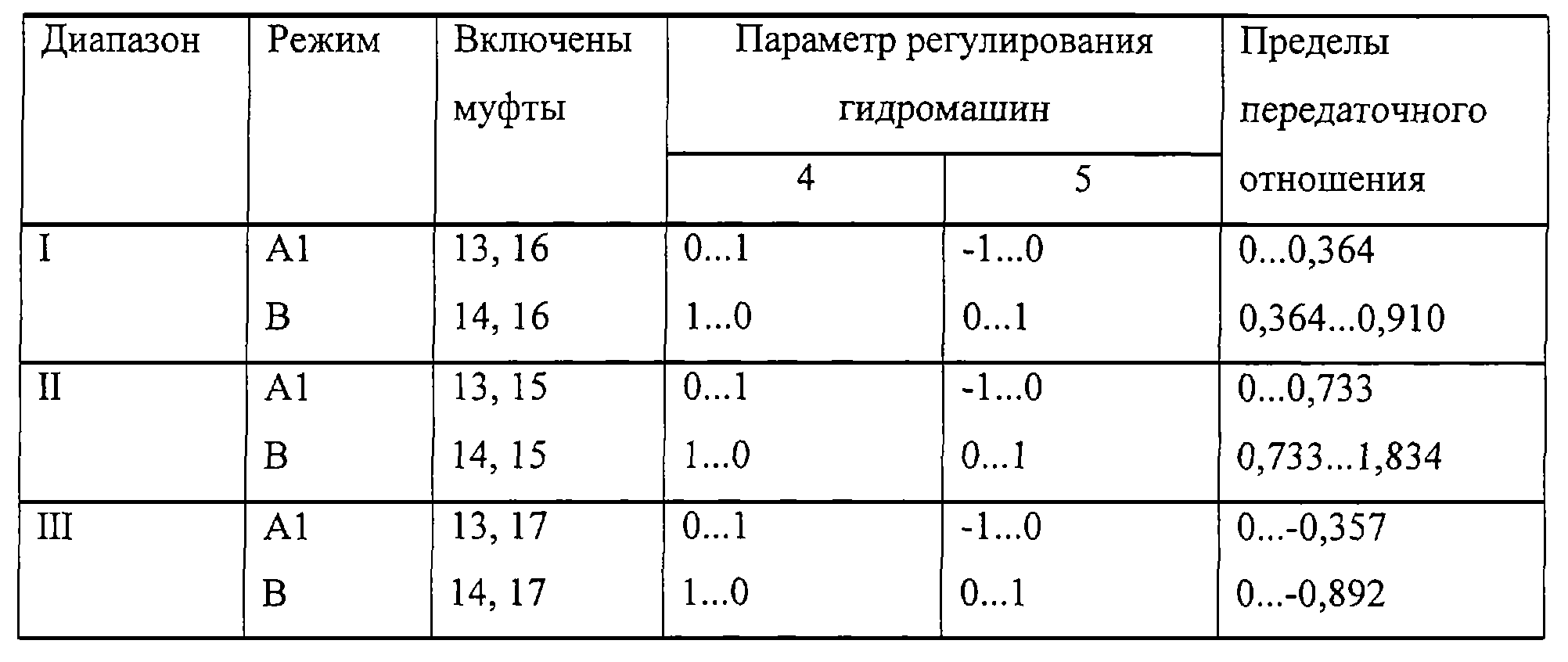
Под передаточным отношением принято отношение оборотов выходного вала к оборотам входного вала; параметр регулирования равен отношению текущего рабочего объема гидромашины к ее максимальному рабочему объему; z12 - число зубьев зубчатого колеса 12.Under the gear ratio is the ratio of the revolutions of the output shaft to the revolutions of the input shaft; the control parameter is equal to the ratio of the current working volume of the hydraulic machine to its maximum working volume; z 12 is the number of gear teeth 12.
На низшем диапазоне I включена муфта 16, что приводит к соединению валов 2 и 3 через зубчатые колеса 28 и 29. Трансмиссия имеет два режима работы: режим А1, когда включена муфта 13, и режим В, когда включена муфта 14. Рассмотрим работу передачи на режиме А1. В нейтральном положении валы 2, 3, центральное колесо с внутренними зубьями 12, зубчатые колеса 22, 23, вал 21 и гидромашина 5 находятся в неподвижном состоянии, а гидромашины 4 и 5 имеют соответственно нулевой и максимальный рабочие объемы. Входной вал 1 приводит в движение водило 7, которое при неподвижном центральном колесе 12 вращает сателлиты 8, 9 и центральные колеса 10, 11 без нагрузки. Центральное колесо 10 приводит в движение гидромашину 4 через зубчатые колеса 20, 19 и вал 18. При трогании машины система управления постепенно увеличивает рабочий объем гидромашины 4 от нулевого до максимального значения, при этом гидромашина 4 приводит в движение через гидромашину 5 и звенья 22, 23, 13, 29, 28, 16 выходной вал 3. Скорость выходного вала 3 и передаточное отношение передачи увеличиваются пропорционально изменению рабочего объема гидромашины 4. Мощность передается с входного вала 1 на водило 7, где разделяется на механический и гидравлический потоки. Механическая мощность направлена через звенья 7, 9, 12 на вал 2, где суммируется с гидравлической мощностью, передающейся через звенья 7, 10, 20, 19, 18 гидромашин 4, 5, звенья 22, 23, 13. Вал 2 приводит в движение выходной вал 3 через зубчатые колеса 29, 28 и муфту 16. С ростом передаточного отношения увеличивается доля передаваемой через гидромашины гидравлической мощности. На режиме А1 гидромашина 4 кинематически связана с центральным колесом 10 планетарного механизма и работает в режиме гидронасоса, а гидромашина 5 работает в режиме гидромотора и связана с выходным валом 3. После достижения максимального рабочего объема гидромашины 4 производится регулирование гидромашины 5 путем уменьшения ее рабочего объема от максимального до нулевого значения, что приводит к уменьшению скорости вращения гидромашины 4 и связанного с ней центрального колеса 10 и к увеличению скорости центрального колеса 12 и связанного с ней выходного вала 3. На данном режиме гидравлическая мощность уменьшается от максимального до нулевого значения. При нулевом рабочем объеме гидромашины 5 происходит остановка гидромашины 4 и связанного с ней центрального колеса 10, а весь поток мощности передается чисто механическим путем.In the lower range I, clutch 16 is engaged, which leads to the connection of shafts 2 and 3 through gears 28 and 29. The transmission has two operating modes: mode A1, when clutch 13 is engaged, and mode B, when clutch 14 is engaged. Consider the transmission A1 mode. In the neutral position, the shafts 2, 3, the central wheel with internal teeth 12, the gears 22, 23, the shaft 21 and the hydraulic machine 5 are stationary, and the hydraulic machines 4 and 5 have zero and maximum working volumes, respectively. The input shaft 1 drives the carrier 7, which, when the central wheel 12 is stationary, rotates the satellites 8, 9 and the central wheels 10, 11 without load. The Central wheel 10 drives the hydraulic machine 4 through the gears 20, 19 and the shaft 18. When starting the machine, the control system gradually increases the working volume of the hydraulic machine 4 from zero to maximum value, while the hydraulic machine 4 drives through the hydraulic machine 5 and links 22, 23 , 13, 29, 28, 16, output shaft 3. The speed of the output shaft 3 and the gear ratio increase in proportion to the change in the working volume of the hydraulic machine 4. The power is transmitted from the input shaft 1 to the carrier 7, where it is divided into mechanical and hydraulic sky streams. The mechanical power is directed through the links 7, 9, 12 to the shaft 2, where it is summed up with the hydraulic power transmitted through the links 7, 10, 20, 19, 18 of the hydraulic machines 4, 5, links 22, 23, 13. The shaft 2 drives the output shaft 3 through gears 29, 28 and clutch 16. As the gear ratio increases, the proportion of hydraulic power transmitted through the hydraulic machines increases. In the A1 mode, the hydraulic machine 4 is kinematically connected to the central wheel 10 of the planetary mechanism and operates in the hydraulic pump mode, and the hydraulic machine 5 operates in the hydraulic motor mode and is connected to the output shaft 3. After reaching the maximum working volume of the hydraulic machine 4, the hydraulic machine 5 is regulated by reducing its working volume from maximum to zero, which leads to a decrease in the speed of rotation of the hydraulic machine 4 and the associated Central wheel 10 and to an increase in the speed of the Central wheel 12 and associated with th output shaft 3. In this mode, the hydraulic power is reduced from maximum to zero. With a zero working volume of the hydraulic machine 5, the hydraulic machine 4 and the associated central wheel 10 are stopped, and the entire power flow is transmitted purely mechanically.
Переключение трансмиссии с режима А1 на режим В происходит путем включения муфты 14. Передаточные числа зубчатых передач подобраны таким образом, что скорости звеньев 25 и 11 равны между собой в момент переключения, что позволяет включить синхронизировано без нагрузки муфту 14 и выключить муфту 13, в результате чего гидромашина 5 соединяется с центральным колесом 11 через звенья 24, 25, 14. Бесступенчатая передача по схеме В характеризуется тем, что гидромашины 4, 5 кинематически связаны с промежуточными звеньями планетарного механизма 10 и 11 соответственно, а входной вал 1 и выходной вал 3 связаны со звеньями планетарного механизма 7 и 12. При этом ни одна из гидромашин не связана с входным или выходным валами. На первом этапе регулируется гидромашина 5 путем увеличения ее рабочего объема от нулевого до максимального значения в обратную сторону по сравнению с режимом А1. Происходит увеличение скорости вращения гидромашины 4 и валов 2, 3, соответственно возрастает передаточное отношение. Гидромашина 4 вращается в обратную сторону по сравнению с режимом А1 и переходит в режим работы гидромотора, а гидромашина 5 переходит в режим работы гидронасоса. Механический поток мощности передается через звенья 7, 9, 12, гидравлическая мощность направлена через звенья 7, 8, 9, 11, 14, 25, 24, 21 гидромашин 5, 4, звенья 19, 20, 10. С увеличением рабочего объема гидромашины 5 происходит рост гидравлического потока мощности и уменьшение механического потока. После достижения гидромашиной 5 максимального объема производится регулирование гидромашины 4 путем уменьшения ее рабочего объема от максимального до нулевого значения, что приводит к замедлению вращения гидромашины 5 и звена 11 и к увеличению скорости вращения центрального колеса 12 и кинематически связанного с ним выходного вала 3. Происходит дальнейшее увеличение передаточного отношения. При максимальном передаточном отношении, когда рабочий объем гидромашины 4 равен нулю, центральное колесо 11 и связанная с ним гидромашина 5 находятся в неподвижном состоянии, а вся мощность передается механическим путем через планетарный механизм.The transmission is switched from A1 to B mode by turning on the clutch 14. The gear ratios of the gears are selected so that the speeds of the links 25 and 11 are equal to each other at the time of switching, which allows the clutch 14 to be switched on synchronously without load and to turn off the clutch 13, as a result of which the hydraulic machine 5 is connected to the Central wheel 11 through links 24, 25, 14. The continuously variable transmission according to scheme B is characterized by the fact that the hydraulic machines 4, 5 are kinematically connected with the intermediate links of the planetary mechanism 10 and 11, respectively Twain and the input shaft 1 and output shaft 3 are connected with the planetary gear units 7 and 12. In this case, none of the hydraulic is not connected to the input or output shafts. At the first stage, the hydraulic machine 5 is regulated by increasing its working volume from zero to the maximum value in the opposite direction compared to mode A1. There is an increase in the speed of rotation of the hydraulic machine 4 and the shafts 2, 3, respectively, increases the gear ratio. The hydraulic machine 4 rotates in the opposite direction compared to the A1 mode and switches to the hydraulic motor operation mode, and the hydraulic machine 5 switches to the hydraulic pump operation mode. The mechanical power flow is transmitted through the links 7, 9, 12, hydraulic power is directed through the links 7, 8, 9, 11, 14, 25, 24, 21 of the hydraulic machines 5, 4, links 19, 20, 10. With an increase in the working volume of the hydraulic machine 5 there is an increase in hydraulic power flow and a decrease in mechanical flow. After the hydraulic machine 5 reaches the maximum volume, the hydraulic machine 4 is regulated by reducing its working volume from the maximum to zero, which leads to a slowdown in the rotation of the hydraulic machine 5 and link 11 and to an increase in the rotation speed of the central wheel 12 and the output shaft 3 kinematically associated with it. increase in gear ratio. At the maximum gear ratio, when the working volume of the hydraulic machine 4 is zero, the central wheel 11 and the associated hydraulic machine 5 are in a stationary state, and all the power is transmitted mechanically through a planetary mechanism.
На втором диапазоне II включена муфта 15 и соединение валов 2 и 3 происходит через зубчатые колеса 26, 27, а на диапазоне заднего хода III включена муфта 17 и соединение валов 2 и 3 происходит через зацепляющиеся зубчатые колеса 30, 31, 32. Работа бесступенчатой передачи и переключение муфт 13 и 14 происходит так же, как и на первом диапазоне. Применение двух и более диапазонов позволяет использовать зоны бесступенчатого регулирования с оптимальными характеристиками в широком диапазоне рабочих скоростей, при этом снижается нагруженность гидромашин и повышается общий КПД.In the second range II, the clutch 15 is turned on and the connection of the shafts 2 and 3 occurs through the gears 26, 27, and in the reverse range III the clutch 17 is turned on and the connection of the shafts 2 and 3 occurs through the gears 30, 31, 32 engaging. and the switching of the clutches 13 and 14 is the same as in the first range. The use of two or more ranges allows the use of zones of stepless regulation with optimal characteristics in a wide range of operating speeds, while the loading of hydraulic machines is reduced and the overall efficiency is increased.
Разделение мощности на механический и гидравлический потоки и отсутствие циркуляции мощности на всех режимах обеспечивает снижение нагрузок на гидромашинах 4, 5 в 3-4 раза, уменьшается давление в гидрообъемной передаче и повышается КПД, который приближается к КПД механических передач. На режимах нулевой гидравлической мощности, когда остановлена одна из гидромашин и вся мощность передается механическим путем, КПД бесступенчатой трансмиссии может превышать КПД аналогичных механических передач. Кинематика четырехзвенного планетарного механизма с парными зацепляющимися сателлитами 8 и 9 устроена таким образом, что достигается равномерное распределение гидравлической мощности между режимами А1 и В, кроме того, установлены новые рациональные связи между гидромашинами и звеньями планетарного механизма. Все это обеспечивает снижение гидравлической мощности до 20-25% от передаваемой мощности, в результате чего уменьшается вес, габариты и повышается КПД заявляемой передачи.The separation of power into mechanical and hydraulic flows and the absence of power circulation in all modes reduces the load on hydraulic machines 4, 5 3-4 times, the pressure in the hydrostatic transmission decreases and the efficiency increases, which approaches the efficiency of mechanical gears. At zero hydraulic power modes, when one of the hydraulic machines is stopped and all the power is transmitted mechanically, the efficiency of a continuously variable transmission can exceed the efficiency of similar mechanical transmissions. The kinematics of a four-link planetary mechanism with paired engaging satellites 8 and 9 is arranged in such a way that a uniform distribution of hydraulic power between modes A1 and B is achieved, in addition, new rational connections between hydraulic machines and links of the planetary mechanism are established. All this provides a reduction in hydraulic power to 20-25% of the transmitted power, resulting in reduced weight, dimensions and increased efficiency of the claimed transmission.
Claims (1)
Priority Applications (1)
| Application Number | Priority Date | Filing Date | Title |
|---|---|---|---|
| RU2002132552A RU2238457C2 (en) | 2002-12-02 | 2002-12-02 | Hydromechanical transmission |
Applications Claiming Priority (1)
| Application Number | Priority Date | Filing Date | Title |
|---|---|---|---|
| RU2002132552A RU2238457C2 (en) | 2002-12-02 | 2002-12-02 | Hydromechanical transmission |
Publications (2)
| Publication Number | Publication Date |
|---|---|
| RU2002132552A RU2002132552A (en) | 2004-06-20 |
| RU2238457C2 true RU2238457C2 (en) | 2004-10-20 |
Family
ID=33537323
Family Applications (1)
| Application Number | Title | Priority Date | Filing Date |
|---|---|---|---|
| RU2002132552A RU2238457C2 (en) | 2002-12-02 | 2002-12-02 | Hydromechanical transmission |
Country Status (1)
| Country | Link |
|---|---|
| RU (1) | RU2238457C2 (en) |
Cited By (2)
| Publication number | Priority date | Publication date | Assignee | Title |
|---|---|---|---|---|
| EA013850B1 (en) * | 2007-04-09 | 2010-08-30 | Республиканское Конструкторское Унитарное Предприятие "Гскб По Зерноуборочной И Кормоуборочной Технике" | Mobile energy device |
| CN104121346A (en) * | 2014-07-16 | 2014-10-29 | 江苏大学 | Single-planet-row confluence hydraulic and mechanical composite double-flow transmission gearbox |
-
2002
- 2002-12-02 RU RU2002132552A patent/RU2238457C2/en not_active IP Right Cessation
Cited By (3)
| Publication number | Priority date | Publication date | Assignee | Title |
|---|---|---|---|---|
| EA013850B1 (en) * | 2007-04-09 | 2010-08-30 | Республиканское Конструкторское Унитарное Предприятие "Гскб По Зерноуборочной И Кормоуборочной Технике" | Mobile energy device |
| CN104121346A (en) * | 2014-07-16 | 2014-10-29 | 江苏大学 | Single-planet-row confluence hydraulic and mechanical composite double-flow transmission gearbox |
| CN104121346B (en) * | 2014-07-16 | 2016-06-08 | 江苏大学 | Single planetary row confluxes hydraulic machinery compound split path transmission wheel box |
Similar Documents
| Publication | Publication Date | Title |
|---|---|---|
| US4304151A (en) | Stepless composite hydrostatic-mechanical transmission | |
| US4286477A (en) | Steplessly adjustable variable-speed hydrostatic-mechanical composite transmission | |
| US8469850B2 (en) | Superposition transmission | |
| CA2344870C (en) | Hydro-mechanical transmission | |
| JP4879345B2 (en) | Transmission and construction vehicle including the same | |
| US3897697A (en) | Infinitely variable drive ratio hydro-mechanical transmission for vehicles or the like | |
| KR20150132840A (en) | Split power infinitely variable transmission architecture | |
| CN109764107B (en) | Variable speed transmission device | |
| US5201691A (en) | Variable speed transmission assembly | |
| AU2001284058A1 (en) | Hydro-mechanical transmission | |
| CN105723121A (en) | Power-split continuously variable transmission apparatus having summing planetary transmission | |
| US5846152A (en) | Continuously variable transmission | |
| US6561942B2 (en) | Dual mode variable ratio transmission | |
| US4976665A (en) | Vehicle drive device with a hydrostatic-mechanical power splitting transmission | |
| US20060276295A1 (en) | Transmission for a motor vehicle with continuously variable power-split drive ranges | |
| GB1593750A (en) | Power coupling transmission | |
| US5277670A (en) | Circuit change-over gear with infinitely variable transmission | |
| RU2238457C2 (en) | Hydromechanical transmission | |
| CN108591411B (en) | Transmission system capable of realizing three variable speed transmission processes | |
| US20160097442A1 (en) | Transmission device with secondarily coupled power split | |
| JP5026424B2 (en) | Continuously variable transmission | |
| RU2554922C1 (en) | Multi-range three-train stageless transmission based on five-link differential gear | |
| RU2460921C1 (en) | Stepless gearbox (versions) | |
| JP7352320B2 (en) | Multi-mode compound transmission device that integrates gears, hydraulic pressure, and pyramids | |
| CN114934984B (en) | Composite transmission device with traction type toroidal continuously variable transmission and control method thereof |
Legal Events
| Date | Code | Title | Description |
|---|---|---|---|
| MM4A | The patent is invalid due to non-payment of fees |
Effective date: 20121203 |