EP2503098B1 - Rotor disk assembly and lock assembly therefor - Google Patents
Rotor disk assembly and lock assembly therefor Download PDFInfo
- Publication number
- EP2503098B1 EP2503098B1 EP12160419.3A EP12160419A EP2503098B1 EP 2503098 B1 EP2503098 B1 EP 2503098B1 EP 12160419 A EP12160419 A EP 12160419A EP 2503098 B1 EP2503098 B1 EP 2503098B1
- Authority
- EP
- European Patent Office
- Prior art keywords
- rotor disk
- assembly
- recited
- heat shield
- slot structure
- Prior art date
- Legal status (The legal status is an assumption and is not a legal conclusion. Google has not performed a legal analysis and makes no representation as to the accuracy of the status listed.)
- Active
Links
- 238000000034 method Methods 0.000 claims description 8
- 230000014759 maintenance of location Effects 0.000 description 6
- 230000000712 assembly Effects 0.000 description 5
- 238000000429 assembly Methods 0.000 description 5
- 125000006850 spacer group Chemical group 0.000 description 5
- 230000008901 benefit Effects 0.000 description 3
- 230000000717 retained effect Effects 0.000 description 3
- 230000006835 compression Effects 0.000 description 2
- 238000007906 compression Methods 0.000 description 2
- 238000009434 installation Methods 0.000 description 2
- 230000036316 preload Effects 0.000 description 2
- 230000004044 response Effects 0.000 description 2
- 235000020637 scallop Nutrition 0.000 description 2
- 241000237509 Patinopecten sp. Species 0.000 description 1
- 241000237503 Pectinidae Species 0.000 description 1
- 238000004891 communication Methods 0.000 description 1
- 230000008878 coupling Effects 0.000 description 1
- 238000010168 coupling process Methods 0.000 description 1
- 238000005859 coupling reaction Methods 0.000 description 1
- 239000000446 fuel Substances 0.000 description 1
- 238000003780 insertion Methods 0.000 description 1
- 230000037431 insertion Effects 0.000 description 1
- 239000012212 insulator Substances 0.000 description 1
- 230000003993 interaction Effects 0.000 description 1
- 230000013011 mating Effects 0.000 description 1
- 238000012986 modification Methods 0.000 description 1
- 230000004048 modification Effects 0.000 description 1
- 230000000452 restraining effect Effects 0.000 description 1
- 230000001052 transient effect Effects 0.000 description 1
- 238000011144 upstream manufacturing Methods 0.000 description 1
Images


Classifications
-
- F—MECHANICAL ENGINEERING; LIGHTING; HEATING; WEAPONS; BLASTING
- F01—MACHINES OR ENGINES IN GENERAL; ENGINE PLANTS IN GENERAL; STEAM ENGINES
- F01D—NON-POSITIVE DISPLACEMENT MACHINES OR ENGINES, e.g. STEAM TURBINES
- F01D5/00—Blades; Blade-carrying members; Heating, heat-insulating, cooling or antivibration means on the blades or the members
- F01D5/02—Blade-carrying members, e.g. rotors
- F01D5/06—Rotors for more than one axial stage, e.g. of drum or multiple disc type; Details thereof, e.g. shafts, shaft connections
- F01D5/066—Connecting means for joining rotor-discs or rotor-elements together, e.g. by a central bolt, by clamps
-
- F—MECHANICAL ENGINEERING; LIGHTING; HEATING; WEAPONS; BLASTING
- F01—MACHINES OR ENGINES IN GENERAL; ENGINE PLANTS IN GENERAL; STEAM ENGINES
- F01D—NON-POSITIVE DISPLACEMENT MACHINES OR ENGINES, e.g. STEAM TURBINES
- F01D5/00—Blades; Blade-carrying members; Heating, heat-insulating, cooling or antivibration means on the blades or the members
- F01D5/02—Blade-carrying members, e.g. rotors
- F01D5/08—Heating, heat-insulating or cooling means
-
- F—MECHANICAL ENGINEERING; LIGHTING; HEATING; WEAPONS; BLASTING
- F01—MACHINES OR ENGINES IN GENERAL; ENGINE PLANTS IN GENERAL; STEAM ENGINES
- F01D—NON-POSITIVE DISPLACEMENT MACHINES OR ENGINES, e.g. STEAM TURBINES
- F01D5/00—Blades; Blade-carrying members; Heating, heat-insulating, cooling or antivibration means on the blades or the members
- F01D5/30—Fixing blades to rotors; Blade roots ; Blade spacers
- F01D5/3007—Fixing blades to rotors; Blade roots ; Blade spacers of axial insertion type
- F01D5/3015—Fixing blades to rotors; Blade roots ; Blade spacers of axial insertion type with side plates
-
- F—MECHANICAL ENGINEERING; LIGHTING; HEATING; WEAPONS; BLASTING
- F05—INDEXING SCHEMES RELATING TO ENGINES OR PUMPS IN VARIOUS SUBCLASSES OF CLASSES F01-F04
- F05D—INDEXING SCHEME FOR ASPECTS RELATING TO NON-POSITIVE-DISPLACEMENT MACHINES OR ENGINES, GAS-TURBINES OR JET-PROPULSION PLANTS
- F05D2250/00—Geometry
- F05D2250/10—Two-dimensional
- F05D2250/13—Two-dimensional trapezoidal
- F05D2250/131—Two-dimensional trapezoidal polygonal
-
- F—MECHANICAL ENGINEERING; LIGHTING; HEATING; WEAPONS; BLASTING
- F05—INDEXING SCHEMES RELATING TO ENGINES OR PUMPS IN VARIOUS SUBCLASSES OF CLASSES F01-F04
- F05D—INDEXING SCHEME FOR ASPECTS RELATING TO NON-POSITIVE-DISPLACEMENT MACHINES OR ENGINES, GAS-TURBINES OR JET-PROPULSION PLANTS
- F05D2250/00—Geometry
- F05D2250/10—Two-dimensional
- F05D2250/13—Two-dimensional trapezoidal
- F05D2250/132—Two-dimensional trapezoidal hexagonal
-
- F—MECHANICAL ENGINEERING; LIGHTING; HEATING; WEAPONS; BLASTING
- F05—INDEXING SCHEMES RELATING TO ENGINES OR PUMPS IN VARIOUS SUBCLASSES OF CLASSES F01-F04
- F05D—INDEXING SCHEME FOR ASPECTS RELATING TO NON-POSITIVE-DISPLACEMENT MACHINES OR ENGINES, GAS-TURBINES OR JET-PROPULSION PLANTS
- F05D2260/00—Function
- F05D2260/30—Retaining components in desired mutual position
- F05D2260/36—Retaining components in desired mutual position by a form fit connection, e.g. by interlocking
-
- Y—GENERAL TAGGING OF NEW TECHNOLOGICAL DEVELOPMENTS; GENERAL TAGGING OF CROSS-SECTIONAL TECHNOLOGIES SPANNING OVER SEVERAL SECTIONS OF THE IPC; TECHNICAL SUBJECTS COVERED BY FORMER USPC CROSS-REFERENCE ART COLLECTIONS [XRACs] AND DIGESTS
- Y10—TECHNICAL SUBJECTS COVERED BY FORMER USPC
- Y10T—TECHNICAL SUBJECTS COVERED BY FORMER US CLASSIFICATION
- Y10T29/00—Metal working
- Y10T29/49—Method of mechanical manufacture
- Y10T29/49229—Prime mover or fluid pump making
- Y10T29/49231—I.C. [internal combustion] engine making
- Y10T29/49234—Rotary or radial engine making
-
- Y—GENERAL TAGGING OF NEW TECHNOLOGICAL DEVELOPMENTS; GENERAL TAGGING OF CROSS-SECTIONAL TECHNOLOGIES SPANNING OVER SEVERAL SECTIONS OF THE IPC; TECHNICAL SUBJECTS COVERED BY FORMER USPC CROSS-REFERENCE ART COLLECTIONS [XRACs] AND DIGESTS
- Y10—TECHNICAL SUBJECTS COVERED BY FORMER USPC
- Y10T—TECHNICAL SUBJECTS COVERED BY FORMER US CLASSIFICATION
- Y10T70/00—Locks
- Y10T70/50—Special application
Definitions
- the present disclosure relates to gas turbine engines, and in particular, to a bayonet lock feature therefor.
- rotor cavities are often separated by full hoop shells which require some form of retention assembly such as a bayonet lock.
- Conventional locks include a plate which is locked with other components such as the rotor blades or a ring.
- US 5 236 302 A discloses a rotor disk assembly according to the preamble of claim 1 and a method according to the preamble of claim 13.
- a rotor disk assembly set forth in claim 1 and a method to assemble a rotor disk assembly set forth in claim 13.
- FIG. 1 schematically illustrates a gas turbine engine 20.
- the gas turbine engine 20 is disclosed herein as two-spool turbofan that generally incorporates a fan section 22, a compressor section 24, a combustor section 26 and a turbine section 28 along an engine central longitudinal axis A.
- Alternative engines might include an augmentor section (not shown) among other systems or features.
- the fan section 22 drives air along a bypass flowpath while the compressor section 24 receives air from the fan section 22 along a core flowpath for compression and communication into the combustor section 26 then expansion through the turbine section 28.
- FIG. 1 schematically illustrates a gas turbine engine 20.
- the gas turbine engine 20 is disclosed herein as two-spool turbofan that generally incorporates a fan section 22, a compressor section 24, a combustor section 26 and a turbine section 28 along an engine central longitudinal axis A.
- Alternative engines might include an augmentor section (not shown) among other systems or features.
- the fan section 22 drives air along a bypass flowpath while the compressor section 24
- the engine 20 generally includes a low speed spool 30 and a high speed spool 32 mounted upon a multiple of bearing systems for rotation about the engine central longitudinal axis A relative to an engine stationary structure.
- the low speed spool 30 generally includes an inner shaft 34 that interconnects a fan 35, a low pressure compressor 36 and a low pressure turbine 38.
- the inner shaft 34 may drive the fan 35 either directly or through a geared architecture 40 to drive the fan 35 at a lower speed than the low speed spool 30.
- the high speed spool 32 includes an outer shaft 42 that interconnects a high pressure compressor 44 and high pressure turbine 46.
- a combustor 48 is arranged between the high pressure compressor 44 and the high pressure turbine 46.
- Core airflow is compressed by the low pressure compressor 36 then the high pressure compressor 44, mixed with the fuel in the combustor 48 then expanded over the high pressure turbine 46 and low pressure turbine 38.
- the turbines 38, 46 rotationally drive the respective low speed spool 30 and high speed spool 32 in response to the expansion.
- the high speed spool 32 generally includes a heat shield 52, a first front cover plate 54, a first turbine rotor disk 56, a first rear cover plate 58, a second front cover plate 60, a second turbine rotor disk 62, and a rear cover plate 64.
- a tie-shaft arrangement may, in one non-limiting embodiment, utilize the outer shaft 42 or a portion thereof as a center tension tie-shaft to axially preload and compress at least the first turbine rotor disk 56 and the second turbine rotor disk 62 therebetween in compression.
- the components may be assembled to the outer shaft 42 from fore-to-aft (or aft-to-fore, depending upon configuration) and then compressed through installation of a locking element to hold the stack in a longitudinal precompressed state to define the high speed spool 32.
- the longitudinal precompressed state maintains axial engagement between the components such that the axial preload maintains the high pressure turbine 46 as a single rotary unit.
- other configurations such as an array of circumferentially-spaced tie rods extending through web portions of the rotor disks, sleeve like spacers or other interference and/or keying arrangements may alternatively or additionally be utilized to provide the tie shaft arrangement.
- Each of the rotor disks 56, 62 is defined about the axis of rotation A to support a respective plurality of turbine blades 66, 68 circumferentially disposed around a periphery thereof.
- the plurality of blades 66, 68 define a portion of a stage downstream of a respective turbine vane structure 70, 72 within the high pressure turbine 46.
- the cover plates 54, 58, 60, 64 operate as air seals for airflow into the respective rotor disks 56, 62.
- the cover plates 54, 58, 60, 64 also operate to segregate air in compartments through engagement with fixed structure such as the turbine vane structure 70, 72.
- the heat shield 52 in the disclosed non-limiting embodiment may be a full hoop heat shield that separates a relatively hotter outer diameter cavity 80 from a relatively cooler inner diameter cavity 82 and spans an interface 84 between the high pressure turbine 46 and the high pressure compressor 44 (illustrated schematically).
- the interface 84 may be a splined interface as a means of rotationally coupling the high pressure turbine 46 and the high pressure compressor 44.
- the heat shield 52 provides a thermal insulator between the relatively hotter outer diameter cavity 80 from the relatively cooler inner diameter cavity 82 to slow the transient thermal response and thereby allow a much smaller initial radial interference fit at contact points 74 between the high pressure turbine 46 and the high pressure compressor 44.
- the mating components between the high pressure turbine 46 and the high pressure compressor 44 in the disclosed non-limiting embodiment are the first turbine rotor disk 56 and the high pressure compressor rear hub 86. Axial retention of the first front cover plate 54 is thereby provided by the heat shield 52 and the first turbine rotor disk 56.
- the heat shield 52 includes a series of radial tabs 88 which extend radially inward from a cylindrical extension 52C of the heat shield 52.
- the heat shield 52 also includes a radially outward flange 52F at an aft end section thereof to abut and provide a radially outward bias to the first front cover plate 54 ( Figure 5 ).
- the series of radial tabs 88 extend in a generally opposite direction relative to the radially outward flange 52F.
- the series of radial tabs 88 function as a bayonet lock to provide axial retention for the first front cover plate 54 to the first turbine rotor disk 56 ( Figure 5 ).
- a flange 90 extends radially outward from a cylindrical extension 56C of the first turbine rotor disk 56 to be adjacent to a cover plate stop 92 which extends radially inward from a cylindrical extension 54C of the first front cover plate 54.
- a circumferentially intermittent slot structure 94 extends radially outward from the cylindrical extension 56C of the first turbine rotor disk 56 just upstream, i.e., axially forward, of the flange 90 to receive the radial tabs 88.
- the first front cover plate 54 is located adjacent to the first turbine rotor disk 56 such that the cover plate stop 92 is adjacent to the flange 90 and may be at least partially axially retained by the radial tabs 88.
- a step surface 52S in the cylindrical extension 52C ( Figure 6 ) may be formed adjacent to the radial tabs 88 to further abut and axially retain the cover plate stop 92.
- the cover plate stop 92 may also be radially engaged with the openings formed by the circumferentially intermittent slot structure 94 to provide an anti-rotation interface.
- the heat shield 52 is located axially adjacent to the first front cover plate 54 such that the radial tabs 88 pass through openings formed by the circumferentially intermittent slot structure 94.
- the heat shield 52 (also shown in Figure 6 ) is then rotated such that the radial tabs 88 are aligned with the circumferentially intermittent slot structure 94. That is, the heat shield 52 operates as an axial retention device for the first front cover plate 54.
- One or more lock assemblies 96 are then inserted in the openings formed by the circumferentially intermittent slot structure 94 to circumferentially lock the heat shield 52 to the first turbine rotor disk 56 and prevent rotation during operation thereof. It should be understood that although the lock assembly 96 is utilized herein to restrain the heat shield 52, other components and systems may alternatively or additionally be retained and used within the lock assembly 96.
- An annular spacer 98 ( Figure 3 ) may be located between the circumferentially intermittent slot structure 94 and the high pressure compressor rear hub 86.
- the annular spacer 98 extends radially above the circumferentially intermittent slot structure 94 to axially trap the lock assembly 96 as well as define the desired axial distance between the high pressure compressor rear hub 86 relative to the cylindrical extension 56C of the first turbine rotor disk 56.
- Each lock assembly 96 generally includes a lock body 100 and a retaining wire 102 ( Figure 7 ). In one non-limiting embodiment, two lock assemblies 96 are arranged 180 degrees apart, however, any number of lock assemblies 96 may alternatively be utilized. The lock assembly 96 is retained in place during assembly and disassembly by the retaining wire 102 that is preassembled to the lock body 100 and engages the circumferentially intermittent slot structure 94 ( Figure 8 ).
- the lock assembly 96 reduces the cost of anti-rotation features such as the annular spacer 98 and integral milled features in that the lock assembly 96 utilizes scallops 93 ( Figure 6 ) formed between the cover plate stops 92. That is, the lock assembly 96 is readily inserted past the scallop 93.
- the lock body 100 is generally rectilinear in shape with rounded edges 106 to smoothly interface with the circumferentially intermittent slot structure 94.
- a lock tab 108 extends from the lock body 100 to axially trap the lock assembly 96 between the radial tab 88 and the annular spacer 98.
- An undercut slot 110 ( Figure 9 ) is located opposite the lock tab to receive the retaining wire 102 which is a polygonal shape.
- the retaining wire 102 includes a break 112 which permits flexibility during insertion and removal from the circumferentially intermittent slot structure 94 as well as installation into the undercut slot.
- the shape of the retaining wire 102 generally includes a opposed linear segments 114A, 114B of which the linear segment 114B includes the break 112 to form an interrupted somewhat elongated hexagonal shape. Rounded vertices 116A, 116B between the opposed linear segments 114A, 114B are readily captured between the circumferentially intermittent slot structure 94 to further facilitate intermediate assembly and disassembly through the snap-in interaction.
Description
- The present disclosure relates to gas turbine engines, and in particular, to a bayonet lock feature therefor.
- In a gas turbine engine, rotor cavities are often separated by full hoop shells which require some form of retention assembly such as a bayonet lock. Conventional locks include a plate which is locked with other components such as the rotor blades or a ring.
-
US 5 236 302 A discloses a rotor disk assembly according to the preamble of claim 1 and a method according to the preamble of claim 13. -
DE 10 2009 003712 A1 discloses an axial retention system for restraining axial movement of a machine component. - According to the present invention, there is provided a rotor disk assembly set forth in claim 1 and a method to assemble a rotor disk assembly set forth in claim 13.
- Various features will become apparent to those skilled in the art from the following detailed description of the disclosed non-limiting embodiment. The drawings that accompany the detailed description can be briefly described as follows:
-
Figure 1 is a schematic cross-section of a gas turbine engine; -
Figure 2 is a sectional view of a high pressure turbine; -
Figure 3 is an enlarged sectional view of the high pressure turbine illustrating a heat shield and axial retention of a cover plate provided thereby; -
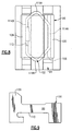
Figure 4 is an exploded perspective view of a rotor disk assembly; -
Figure 5 is a perspective view of the rotor disk assembly; and -
Figure 6 is an expanded view of an interface between a heat shield, cover plate, and rotor disk of the rotor disk assembly -
Figure 7 is an expanded perspective view of a lock assembly; -
Figure 8 is an expanded top partial phantom view of the lock assembly; and -
Figure 9 is an expanded side view of the lock assembly. -
Figure 1 schematically illustrates agas turbine engine 20. Thegas turbine engine 20 is disclosed herein as two-spool turbofan that generally incorporates a fan section 22, a compressor section 24, a combustor section 26 and aturbine section 28 along an engine central longitudinal axis A. Alternative engines might include an augmentor section (not shown) among other systems or features. The fan section 22 drives air along a bypass flowpath while the compressor section 24 receives air from the fan section 22 along a core flowpath for compression and communication into the combustor section 26 then expansion through theturbine section 28. Although depicted as a turbofan gas turbine engine in the disclosed non-limiting embodiment, it should be understood that the concepts described herein are not limited to use with turbofans as the teachings may be applied to other types of turbine engines. - The
engine 20 generally includes alow speed spool 30 and ahigh speed spool 32 mounted upon a multiple of bearing systems for rotation about the engine central longitudinal axis A relative to an engine stationary structure. Thelow speed spool 30 generally includes aninner shaft 34 that interconnects afan 35, alow pressure compressor 36 and alow pressure turbine 38. Theinner shaft 34 may drive thefan 35 either directly or through a gearedarchitecture 40 to drive thefan 35 at a lower speed than thelow speed spool 30. Thehigh speed spool 32 includes anouter shaft 42 that interconnects ahigh pressure compressor 44 andhigh pressure turbine 46. Acombustor 48 is arranged between thehigh pressure compressor 44 and thehigh pressure turbine 46. - Core airflow is compressed by the
low pressure compressor 36 then thehigh pressure compressor 44, mixed with the fuel in thecombustor 48 then expanded over thehigh pressure turbine 46 andlow pressure turbine 38. Theturbines low speed spool 30 andhigh speed spool 32 in response to the expansion. - With reference to
Figure 2 , thehigh speed spool 32 generally includes aheat shield 52, a firstfront cover plate 54, a firstturbine rotor disk 56, a firstrear cover plate 58, a secondfront cover plate 60, a secondturbine rotor disk 62, and arear cover plate 64. Although two rotor disk assemblies are illustrated in the disclosed non-limiting embodiment, it should be understood that any number of rotor disk assemblies will benefit herefrom. A tie-shaft arrangement may, in one non-limiting embodiment, utilize theouter shaft 42 or a portion thereof as a center tension tie-shaft to axially preload and compress at least the firstturbine rotor disk 56 and the secondturbine rotor disk 62 therebetween in compression. - The components may be assembled to the
outer shaft 42 from fore-to-aft (or aft-to-fore, depending upon configuration) and then compressed through installation of a locking element to hold the stack in a longitudinal precompressed state to define thehigh speed spool 32. The longitudinal precompressed state maintains axial engagement between the components such that the axial preload maintains thehigh pressure turbine 46 as a single rotary unit. It should be understood that other configurations such as an array of circumferentially-spaced tie rods extending through web portions of the rotor disks, sleeve like spacers or other interference and/or keying arrangements may alternatively or additionally be utilized to provide the tie shaft arrangement. - Each of the
rotor disks turbine blades blades turbine vane structure 70, 72 within thehigh pressure turbine 46. Thecover plates respective rotor disks cover plates turbine vane structure 70, 72. - With reference to
Figure 3 , theheat shield 52 in the disclosed non-limiting embodiment may be a full hoop heat shield that separates a relatively hotterouter diameter cavity 80 from a relatively coolerinner diameter cavity 82 and spans aninterface 84 between thehigh pressure turbine 46 and the high pressure compressor 44 (illustrated schematically). Theinterface 84 may be a splined interface as a means of rotationally coupling thehigh pressure turbine 46 and thehigh pressure compressor 44. Theheat shield 52 provides a thermal insulator between the relatively hotterouter diameter cavity 80 from the relatively coolerinner diameter cavity 82 to slow the transient thermal response and thereby allow a much smaller initial radial interference fit atcontact points 74 between thehigh pressure turbine 46 and thehigh pressure compressor 44. - The mating components between the
high pressure turbine 46 and thehigh pressure compressor 44 in the disclosed non-limiting embodiment are the firstturbine rotor disk 56 and the high pressure compressorrear hub 86. Axial retention of the firstfront cover plate 54 is thereby provided by theheat shield 52 and the firstturbine rotor disk 56. - With reference to
Figure 4 , theheat shield 52 includes a series ofradial tabs 88 which extend radially inward from acylindrical extension 52C of theheat shield 52. Theheat shield 52 also includes a radiallyoutward flange 52F at an aft end section thereof to abut and provide a radially outward bias to the first front cover plate 54 (Figure 5 ). The series ofradial tabs 88 extend in a generally opposite direction relative to the radiallyoutward flange 52F. The series ofradial tabs 88 function as a bayonet lock to provide axial retention for the firstfront cover plate 54 to the first turbine rotor disk 56 (Figure 5 ). - A
flange 90 extends radially outward from acylindrical extension 56C of the firstturbine rotor disk 56 to be adjacent to acover plate stop 92 which extends radially inward from acylindrical extension 54C of the firstfront cover plate 54. A circumferentiallyintermittent slot structure 94 extends radially outward from thecylindrical extension 56C of the firstturbine rotor disk 56 just upstream, i.e., axially forward, of theflange 90 to receive theradial tabs 88. Although a particular circumferentiallyintermittent slot structure 94 which is defined by circumferentially intermittent pairs of axially separated and radially extended tabs is illustrated in the disclosed non-limiting embodiment, it should be understood that various types of lugs may alternatively be utilized. - In a method of assembly, the first
front cover plate 54 is located adjacent to the firstturbine rotor disk 56 such that thecover plate stop 92 is adjacent to theflange 90 and may be at least partially axially retained by theradial tabs 88. Astep surface 52S in thecylindrical extension 52C (Figure 6 ) may be formed adjacent to theradial tabs 88 to further abut and axially retain thecover plate stop 92. Thecover plate stop 92 may also be radially engaged with the openings formed by the circumferentiallyintermittent slot structure 94 to provide an anti-rotation interface. - The
heat shield 52 is located axially adjacent to the firstfront cover plate 54 such that theradial tabs 88 pass through openings formed by the circumferentiallyintermittent slot structure 94. The heat shield 52 (also shown inFigure 6 ) is then rotated such that theradial tabs 88 are aligned with the circumferentiallyintermittent slot structure 94. That is, theheat shield 52 operates as an axial retention device for the firstfront cover plate 54. One ormore lock assemblies 96 are then inserted in the openings formed by the circumferentiallyintermittent slot structure 94 to circumferentially lock theheat shield 52 to the firstturbine rotor disk 56 and prevent rotation during operation thereof. It should be understood that although thelock assembly 96 is utilized herein to restrain theheat shield 52, other components and systems may alternatively or additionally be retained and used within thelock assembly 96. - An annular spacer 98 (
Figure 3 ) may be located between the circumferentiallyintermittent slot structure 94 and the high pressure compressorrear hub 86. Theannular spacer 98 extends radially above the circumferentiallyintermittent slot structure 94 to axially trap thelock assembly 96 as well as define the desired axial distance between the high pressure compressorrear hub 86 relative to thecylindrical extension 56C of the firstturbine rotor disk 56. - Each
lock assembly 96 generally includes alock body 100 and a retaining wire 102 (Figure 7 ). In one non-limiting embodiment, twolock assemblies 96 are arranged 180 degrees apart, however, any number oflock assemblies 96 may alternatively be utilized. Thelock assembly 96 is retained in place during assembly and disassembly by theretaining wire 102 that is preassembled to thelock body 100 and engages the circumferentially intermittent slot structure 94 (Figure 8 ). - The
lock assembly 96 reduces the cost of anti-rotation features such as theannular spacer 98 and integral milled features in that thelock assembly 96 utilizes scallops 93 (Figure 6 ) formed between the cover plate stops 92. That is, thelock assembly 96 is readily inserted past thescallop 93. - With reference to
Figure 8 , thelock body 100 is generally rectilinear in shape with roundededges 106 to smoothly interface with the circumferentiallyintermittent slot structure 94. Alock tab 108 extends from thelock body 100 to axially trap thelock assembly 96 between theradial tab 88 and theannular spacer 98. An undercut slot 110 (Figure 9 ) is located opposite the lock tab to receive theretaining wire 102 which is a polygonal shape. - The
retaining wire 102 includes abreak 112 which permits flexibility during insertion and removal from the circumferentiallyintermittent slot structure 94 as well as installation into the undercut slot. The shape of theretaining wire 102 generally includes a opposedlinear segments linear segment 114B includes thebreak 112 to form an interrupted somewhat elongated hexagonal shape.Rounded vertices linear segments intermittent slot structure 94 to further facilitate intermediate assembly and disassembly through the snap-in interaction. - It should be understood that like reference numerals identify corresponding or similar elements throughout the several drawings. It should also be understood that although a particular component arrangement is disclosed in the illustrated embodiment, other arrangements will benefit herefrom.
- Although particular step sequences are shown, described, and claimed, it should be understood that steps may be performed in any order, separated or combined unless otherwise indicated and will still benefit from the present invention.
- The foregoing description is exemplary rather than defined by the limitations within. Various non-limiting embodiments are disclosed herein, however, one of ordinary skill in the art would recognize that various modifications and variations in light of the above teachings will fall within the scope of the appended claims. It is therefore to be understood that within the scope of the appended claims, the invention may be practiced other than as specifically described. For that reason the appended claims should be studied to determine true scope and content.
Claims (15)
- A rotor disk assembly for a gas turbine engine comprising:a rotor disk (56) defined about an axis of rotation, said rotor disk (56) having a circumferentially intermittent slot structure (94) that extends radially outward relative to said axis of rotation;a component (52) defined about said axis of rotation, said component (52) having a multiple of radial tabs (88) which extend radially inward relative to said axis of rotation, said multiple of radial tabs (88) engageable with said circumferentially intermittent slot structure (94); anda lock assembly (96) engaged with at least one opening formed by said circumferentially intermittent slot structure (94) to provide an anti-rotation interface for said component (52)the rotor disk assembly characterized in that:said lock assembly (96) comprises a retaining wire that defines a polygon shape, said retaining wire (102) engaged with at least one opening formed by said circumferentially intermittent slot structure (94) to provide an anti-rotation interface for said component (52).
- The rotor disk assembly as recited in claim 1, wherein said component (52) is a heat shield.
- The rotor disk assembly as recited in claim 2, wherein said heat shield (52) separates relatively hotter outer diameter cavity (80) from a relatively cooler inner diameter cavity (82).
- The rotor disk assembly as recited in claim 2 or 3, wherein said heat shield (52) spans an interface (84).
- The rotor disk assembly as recited in claim 4, wherein said interface (84) is a splined interface between a high pressure turbine (46) and a high pressure compressor (44).
- The rotor disk assembly as recited in any preceding claim, wherein said circumferentially intermittent slot structure (94) extends radially outward from a cylindrical extension (56C) from said rotor disk (56).
- The rotor disk assembly as recited in any preceding claim, wherein rotor disk (56) is a turbine rotor disk.
- The rotor assembly as recited in any preceding claims, wherein the lock assembly (96) comprises:a lock body (100) with an undercut slot (110); andsaid retaining wire (102) is engageable within said undercut slot (110).
- The rotor assembly as recited in claim 8, wherein said retaining wire (102) defines an elongated hexagonal shape.
- The rotor assembly as recited in claim 8 or 9, wherein said retaining wire (102) includes opposed linear segments (114A, 114B), one of which includes a break (112).
- The rotor assembly as recited in claim 10, wherein said retaining wire (102) includes rounded vertices (116A, 116B) between said opposed linear segments (114A, 114B).
- A method to assemble a rotor disk assembly comprising:locating a cover plate (54) adjacent to a rotor disk (56) along an axis of rotation;axially locating a heat shield (52) having a multiple of radial tabs (88) which extend radially inward relative to the axis of rotation, the multiple of radial tabs (88) axially aligned with openings defined by a circumferentially intermittent slot structure (94) on the rotor disk (56); andengaging a lock assembly (96) with the circumferentially intermittent slot structure (94) to provide an anti-rotation interface for the heat shield (52);the method characterized in that it comprises:rotating the heat shield (52) to radially align the multiple of radial tabs (88) with the circumferentially intermittent slot structure (94) to axially retain the cover plate (54) to the rotor disk (56); andengaging a retaining wire (102) of a lock assembly (96) with the circumferentially intermittent slot structure (94) to provide an anti-rotation interface for the heat shield (52), said retaining wire having a polygonal shape.
- A method as recited in claim 12, further comprising snapping the retaining wire (102) of the lock assembly (96) into the circumferentially intermittent slot structure (94).
- A method as recited in claim 12 or 13, further comprising spanning an interface (84) with the heat shield (52).
- A method as recited in claim 14, further comprising spanning a splined interface (84), between a high pressure turbine (46) and a high pressure compressor (44), with the heat shield (52).
Applications Claiming Priority (1)
| Application Number | Priority Date | Filing Date | Title |
|---|---|---|---|
| US13/053,134 US8840375B2 (en) | 2011-03-21 | 2011-03-21 | Component lock for a gas turbine engine |
Publications (3)
| Publication Number | Publication Date |
|---|---|
| EP2503098A2 EP2503098A2 (en) | 2012-09-26 |
| EP2503098A3 EP2503098A3 (en) | 2015-02-25 |
| EP2503098B1 true EP2503098B1 (en) | 2016-05-11 |
Family
ID=45888011
Family Applications (1)
| Application Number | Title | Priority Date | Filing Date |
|---|---|---|---|
| EP12160419.3A Active EP2503098B1 (en) | 2011-03-21 | 2012-03-20 | Rotor disk assembly and lock assembly therefor |
Country Status (2)
| Country | Link |
|---|---|
| US (1) | US8840375B2 (en) |
| EP (1) | EP2503098B1 (en) |
Families Citing this family (27)
| Publication number | Priority date | Publication date | Assignee | Title |
|---|---|---|---|---|
| FR2985766B1 (en) * | 2012-01-16 | 2016-07-22 | Snecma | ARRANGEMENT FOR GUIDING THE FLOW OF A LIQUID IN RELATION TO THE ROTOR OF A TURBOMACHINE |
| US9303521B2 (en) * | 2012-09-27 | 2016-04-05 | United Technologies Corporation | Interstage coverplate assembly for arranging between adjacent rotor stages of a rotor assembly |
| US9297422B2 (en) * | 2012-10-25 | 2016-03-29 | Pratt & Whitney Canada Corp. | Coupling element for torque transmission in a gas turbine engine |
| EP3693543A1 (en) | 2013-04-18 | 2020-08-12 | United Technologies Corporation | Turbine minidisk bumper for gas turbine engine |
| EP2808490A1 (en) * | 2013-05-29 | 2014-12-03 | Alstom Technology Ltd | Turbine blade with locking pin |
| US9869190B2 (en) | 2014-05-30 | 2018-01-16 | General Electric Company | Variable-pitch rotor with remote counterweights |
| FR3026430B1 (en) * | 2014-09-29 | 2020-07-10 | Safran Aircraft Engines | TURBINE WHEEL IN A TURBOMACHINE |
| US10072510B2 (en) | 2014-11-21 | 2018-09-11 | General Electric Company | Variable pitch fan for gas turbine engine and method of assembling the same |
| US10018063B2 (en) * | 2015-06-10 | 2018-07-10 | United Technologies Corporation | Anti-rotation knife edge seals and gas turbine engines including the same |
| US10100653B2 (en) | 2015-10-08 | 2018-10-16 | General Electric Company | Variable pitch fan blade retention system |
| CA3008617A1 (en) | 2015-12-28 | 2017-07-06 | Lydall, Inc. | Heat shield with retention feature |
| US10145249B2 (en) | 2016-02-23 | 2018-12-04 | Mechanical Dynamics & Analysis Llc | Turbine bucket lockwire anti-rotation device for gas turbine engine |
| US10329929B2 (en) * | 2016-03-15 | 2019-06-25 | United Technologies Corporation | Retaining ring axially loaded against segmented disc surface |
| US10323519B2 (en) * | 2016-06-23 | 2019-06-18 | United Technologies Corporation | Gas turbine engine having a turbine rotor with torque transfer and balance features |
| US10344622B2 (en) | 2016-07-22 | 2019-07-09 | United Technologies Corporation | Assembly with mistake proof bayoneted lug |
| CA2998258A1 (en) * | 2017-05-04 | 2018-11-04 | Rolls-Royce Corporation | Turbine assembly with auxiliary wheel |
| US10968744B2 (en) | 2017-05-04 | 2021-04-06 | Rolls-Royce Corporation | Turbine rotor assembly having a retaining collar for a bayonet mount |
| US10865646B2 (en) * | 2017-05-04 | 2020-12-15 | Rolls-Royce Corporation | Turbine assembly with auxiliary wheel |
| US10774678B2 (en) | 2017-05-04 | 2020-09-15 | Rolls-Royce Corporation | Turbine assembly with auxiliary wheel |
| US10385874B2 (en) * | 2017-05-08 | 2019-08-20 | Solar Turbines Incorporated | Pin to reduce relative rotational movement of disk and spacer of turbine engine |
| FR3073001B1 (en) * | 2017-10-26 | 2021-07-23 | Safran Aircraft Engines | TURBINE DISC ASSEMBLY |
| US11168565B2 (en) | 2018-08-28 | 2021-11-09 | Raytheon Technologies Corporation | Heat shield insert |
| FR3092861B1 (en) * | 2019-02-18 | 2023-02-10 | Safran Aircraft Engines | TURBOMACHINE ASSEMBLY INCLUDING A CLEAT ON A SEALING RING |
| US11371375B2 (en) | 2019-08-19 | 2022-06-28 | Raytheon Technologies Corporation | Heatshield with damper member |
| US11414993B1 (en) * | 2021-03-23 | 2022-08-16 | Pratt & Whitney Canada Corp. | Retaining assembly with anti-rotation feature |
| US11674435B2 (en) | 2021-06-29 | 2023-06-13 | General Electric Company | Levered counterweight feathering system |
| US11795964B2 (en) | 2021-07-16 | 2023-10-24 | General Electric Company | Levered counterweight feathering system |
Family Cites Families (105)
| Publication number | Priority date | Publication date | Assignee | Title |
|---|---|---|---|---|
| FR966804A (en) | 1947-03-11 | 1950-10-19 | Rolls Royce | Gas turbine engine improvements |
| US2788951A (en) | 1951-02-15 | 1957-04-16 | Power Jets Res & Dev Ltd | Cooling of turbine rotors |
| DE1070880B (en) | 1956-12-19 | 1959-12-10 | Rolls-Royce Limited, Derby (Großbritannien) | Gas turbine unit with turbo compressor |
| US2988325A (en) | 1957-07-18 | 1961-06-13 | Rolls Royce | Rotary fluid machine with means supplying fluid to rotor blade passages |
| US3451653A (en) * | 1967-03-22 | 1969-06-24 | Gen Electric | Turbomachinery rotors |
| US3952391A (en) * | 1974-07-22 | 1976-04-27 | General Motors Corporation | Turbine blade with configured stalk |
| US4004860A (en) | 1974-07-22 | 1977-01-25 | General Motors Corporation | Turbine blade with configured stalk |
| GB1479332A (en) | 1974-11-06 | 1977-07-13 | Rolls Royce | Means for retaining blades to a disc or like structure |
| US3982852A (en) | 1974-11-29 | 1976-09-28 | General Electric Company | Bore vane assembly for use with turbine discs having bore entry cooling |
| US3997962A (en) | 1975-06-06 | 1976-12-21 | United Technologies Corporation | Method and tool for removing turbine from gas turbine twin spool engine |
| AR210634A1 (en) | 1976-02-09 | 1977-08-31 | Westinghouse Electric Corp | SPLIT TREE GAS TURBINE |
| DE2633291C3 (en) | 1976-07-23 | 1981-05-14 | Kraftwerk Union AG, 4330 Mülheim | Gas turbine system with cooling by two independent cooling air flows |
| GB2042652B (en) | 1979-02-21 | 1983-07-20 | Rolls Royce | Joint making packing |
| US4480958A (en) | 1983-02-09 | 1984-11-06 | The United States Of America As Represented By The Secretary Of The Air Force | High pressure turbine rotor two-piece blade retainer |
| US4576547A (en) | 1983-11-03 | 1986-03-18 | United Technologies Corporation | Active clearance control |
| US4582467A (en) | 1983-12-22 | 1986-04-15 | United Technologies Corporation | Two stage rotor assembly with improved coolant flow |
| US4669959A (en) | 1984-07-23 | 1987-06-02 | United Technologies Corporation | Breach lock anti-rotation key |
| US4645416A (en) | 1984-11-01 | 1987-02-24 | United Technologies Corporation | Valve and manifold for compressor bore heating |
| US4664599A (en) | 1985-05-01 | 1987-05-12 | United Technologies Corporation | Two stage turbine rotor assembly |
| DE222679T1 (en) | 1985-11-04 | 1987-10-15 | United Technologies Corp., Hartford, Conn., Us | SIDE PLATE FOR A TURBINE DISC. |
| US4882902A (en) | 1986-04-30 | 1989-11-28 | General Electric Company | Turbine cooling air transferring apparatus |
| US4737076A (en) * | 1986-10-20 | 1988-04-12 | United Technologies Corporation | Means for maintaining concentricity of rotating components |
| FR2607866B1 (en) | 1986-12-03 | 1991-04-12 | Snecma | FIXING AXES OF TURBOMACHINE ROTORS, MOUNTING METHOD AND ROTORS THUS MOUNTED |
| GB8705216D0 (en) | 1987-03-06 | 1987-04-08 | Rolls Royce Plc | Rotor assembly |
| US4820116A (en) | 1987-09-18 | 1989-04-11 | United Technologies Corporation | Turbine cooling for gas turbine engine |
| US4822244A (en) | 1987-10-15 | 1989-04-18 | United Technologies Corporation | Tobi |
| JP2756117B2 (en) | 1987-11-25 | 1998-05-25 | 株式会社日立製作所 | Gas turbine rotor |
| US4846628A (en) * | 1988-12-23 | 1989-07-11 | United Technologies Corporation | Rotor assembly for a turbomachine |
| US4890981A (en) | 1988-12-30 | 1990-01-02 | General Electric Company | Boltless rotor blade retainer |
| FR2663997B1 (en) | 1990-06-27 | 1993-12-24 | Snecma | DEVICE FOR FIXING A REVOLUTION CROWN ON A TURBOMACHINE DISC. |
| ES2084139T3 (en) | 1990-06-27 | 1996-05-01 | Ciba Geigy Ag | AZOIC DYES WITH 2-ALKYLAMINO-3-CIANO-4,6-DIAMINOPYRIDIDS AS COMPONENT COMPONENTS. |
| US5151013A (en) * | 1990-12-27 | 1992-09-29 | United Technologies Corporation | Blade lock for a rotor disk and rotor blade assembly |
| US5288210A (en) * | 1991-10-30 | 1994-02-22 | General Electric Company | Turbine disk attachment system |
| US5472313A (en) | 1991-10-30 | 1995-12-05 | General Electric Company | Turbine disk cooling system |
| US5236302A (en) * | 1991-10-30 | 1993-08-17 | General Electric Company | Turbine disk interstage seal system |
| US5275534A (en) | 1991-10-30 | 1994-01-04 | General Electric Company | Turbine disk forward seal assembly |
| US5215440A (en) * | 1991-10-30 | 1993-06-01 | General Electric Company | Interstage thermal shield with asymmetric bore |
| US5232335A (en) | 1991-10-30 | 1993-08-03 | General Electric Company | Interstage thermal shield retention system |
| US5320488A (en) | 1993-01-21 | 1994-06-14 | General Electric Company | Turbine disk interstage seal anti-rotation system |
| US5338154A (en) * | 1993-03-17 | 1994-08-16 | General Electric Company | Turbine disk interstage seal axial retaining ring |
| US5318405A (en) * | 1993-03-17 | 1994-06-07 | General Electric Company | Turbine disk interstage seal anti-rotation key through disk dovetail slot |
| US5537814A (en) * | 1994-09-28 | 1996-07-23 | General Electric Company | High pressure gas generator rotor tie rod system for gas turbine engine |
| US5601741A (en) | 1994-11-18 | 1997-02-11 | Illinois Tool Works, Inc. | Method and apparatus for receiving a universal input voltage in a welding power source |
| KR100389990B1 (en) | 1995-04-06 | 2003-11-17 | 가부시끼가이샤 히다치 세이사꾸쇼 | Gas turbine |
| GB9517369D0 (en) * | 1995-08-24 | 1995-10-25 | Rolls Royce Plc | Bladed rotor |
| FR2744761B1 (en) | 1996-02-08 | 1998-03-13 | Snecma | LABYRINTH DISC WITH INCORPORATED STIFFENER FOR TURBOMACHINE ROTOR |
| GB2317652B (en) | 1996-09-26 | 2000-05-17 | Rolls Royce Plc | Seal arrangement |
| US6393829B2 (en) | 1996-11-29 | 2002-05-28 | Hitachi, Ltd. | Coolant recovery type gas turbine |
| US5862666A (en) | 1996-12-23 | 1999-01-26 | Pratt & Whitney Canada Inc. | Turbine engine having improved thrust bearing load control |
| DE19654471B4 (en) * | 1996-12-27 | 2006-05-24 | Alstom | Rotor of a turbomachine |
| GB2332024B (en) | 1997-12-03 | 2000-12-13 | Rolls Royce Plc | Rotary assembly |
| US6077035A (en) | 1998-03-27 | 2000-06-20 | Pratt & Whitney Canada Corp. | Deflector for controlling entry of cooling air leakage into the gaspath of a gas turbine engine |
| US6035627A (en) | 1998-04-21 | 2000-03-14 | Pratt & Whitney Canada Inc. | Turbine engine with cooled P3 air to impeller rear cavity |
| US6053697A (en) | 1998-06-26 | 2000-04-25 | General Electric Company | Trilobe mounting with anti-rotation apparatus for an air duct in a gas turbine rotor |
| FR2782539B1 (en) | 1998-08-20 | 2000-10-06 | Snecma | TURBOMACHINE HAVING A PRESSURIZED GAS SUPPLY DEVICE |
| US6224329B1 (en) | 1999-01-07 | 2001-05-01 | Siemens Westinghouse Power Corporation | Method of cooling a combustion turbine |
| US6227801B1 (en) | 1999-04-27 | 2001-05-08 | Pratt & Whitney Canada Corp. | Turbine engine having improved high pressure turbine cooling |
| US6283712B1 (en) | 1999-09-07 | 2001-09-04 | General Electric Company | Cooling air supply through bolted flange assembly |
| GB9925261D0 (en) * | 1999-10-27 | 1999-12-29 | Rolls Royce Plc | Locking devices |
| US6375429B1 (en) | 2001-02-05 | 2002-04-23 | General Electric Company | Turbomachine blade-to-rotor sealing arrangement |
| FR2825413B1 (en) | 2001-05-31 | 2003-09-05 | Snecma Moteurs | DEVICE FOR TAKING AIR BY CENTRIPIC FLOW |
| US6575703B2 (en) | 2001-07-20 | 2003-06-10 | General Electric Company | Turbine disk side plate |
| US6901821B2 (en) * | 2001-11-20 | 2005-06-07 | United Technologies Corporation | Stator damper anti-rotation assembly |
| US6877950B2 (en) | 2001-11-29 | 2005-04-12 | Pratt & Whitney Canada Corp. | Method and device for minimizing oil consumption in a gas turbine engine |
| DE10159670A1 (en) | 2001-12-05 | 2003-06-18 | Rolls Royce Deutschland | Vortex rectifier in the high pressure compressor of a gas turbine |
| US6749400B2 (en) | 2002-08-29 | 2004-06-15 | General Electric Company | Gas turbine engine disk rim with axially cutback and circumferentially skewed cooling air slots |
| FR2850130B1 (en) | 2003-01-16 | 2006-01-20 | Snecma Moteurs | DEVICE FOR RETAINING AN ANNULAR FLASK AGAINST A RADIAL FACE OF A DISK |
| US6899520B2 (en) | 2003-09-02 | 2005-05-31 | General Electric Company | Methods and apparatus to reduce seal rubbing within gas turbine engines |
| US6910852B2 (en) | 2003-09-05 | 2005-06-28 | General Electric Company | Methods and apparatus for cooling gas turbine engine rotor assemblies |
| US6960060B2 (en) | 2003-11-20 | 2005-11-01 | General Electric Company | Dual coolant turbine blade |
| US6981841B2 (en) | 2003-11-20 | 2006-01-03 | General Electric Company | Triple circuit turbine cooling |
| GB2410984B (en) * | 2004-02-14 | 2006-03-08 | Rolls Royce Plc | Securing assembly |
| US7059831B2 (en) | 2004-04-15 | 2006-06-13 | United Technologies Corporation | Turbine engine disk spacers |
| GB0413652D0 (en) * | 2004-06-18 | 2004-07-21 | Rolls Royce Plc | Gas turbine engine structure |
| FR2873161B1 (en) * | 2004-07-15 | 2008-10-10 | Snecma Moteurs Sa | ASSEMBLY COMPRISING A ROTARY SHAFT AND A BEARING BEARING |
| US7229249B2 (en) | 2004-08-27 | 2007-06-12 | Pratt & Whitney Canada Corp. | Lightweight annular interturbine duct |
| US7229247B2 (en) | 2004-08-27 | 2007-06-12 | Pratt & Whitney Canada Corp. | Duct with integrated baffle |
| GB0423363D0 (en) * | 2004-10-21 | 2004-11-24 | Rolls Royce Plc | Rotor assembly retaining apparatus |
| US7179049B2 (en) | 2004-12-10 | 2007-02-20 | Pratt & Whitney Canada Corp. | Gas turbine gas path contour |
| US7520718B2 (en) | 2005-07-18 | 2009-04-21 | Siemens Energy, Inc. | Seal and locking plate for turbine rotor assembly between turbine blade and turbine vane |
| FR2888897B1 (en) * | 2005-07-21 | 2007-10-19 | Snecma | DEVICE FOR DAMPING THE VIBRATION OF AN AXIAL RETAINING RING OF BLOWER BLADES OF A TURBOMACHINE |
| FR2889565B1 (en) | 2005-08-03 | 2012-05-18 | Snecma | CENTRAL AIR SUPPLY COMPRESSOR |
| US7344354B2 (en) | 2005-09-08 | 2008-03-18 | General Electric Company | Methods and apparatus for operating gas turbine engines |
| US7458774B2 (en) | 2005-12-20 | 2008-12-02 | General Electric Company | High pressure turbine disk hub with curved hub surface and method |
| US7578656B2 (en) | 2005-12-20 | 2009-08-25 | General Electric Company | High pressure turbine disk hub with reduced axial stress and method |
| US7331763B2 (en) | 2005-12-20 | 2008-02-19 | General Electric Company | Turbine disk |
| JP2007247406A (en) * | 2006-03-13 | 2007-09-27 | Ihi Corp | Holding structure of fan blade |
| US7743613B2 (en) | 2006-11-10 | 2010-06-29 | General Electric Company | Compound turbine cooled engine |
| US8267664B2 (en) * | 2008-04-04 | 2012-09-18 | General Electric Company | Axial compressor blade retention |
| GB0809759D0 (en) | 2008-05-30 | 2008-07-09 | Rolls Royce Plc | Gas turbine engine |
| US8240987B2 (en) | 2008-08-15 | 2012-08-14 | United Technologies Corp. | Gas turbine engine systems involving baffle assemblies |
| GB2463036B (en) * | 2008-08-29 | 2011-04-20 | Rolls Royce Plc | A blade arrangement |
| US8215902B2 (en) | 2008-10-15 | 2012-07-10 | United Technologies Corporation | Scalable high pressure compressor variable vane actuation arm |
| US8287242B2 (en) | 2008-11-17 | 2012-10-16 | United Technologies Corporation | Turbine engine rotor hub |
| US20100150711A1 (en) | 2008-12-12 | 2010-06-17 | United Technologies Corporation | Apparatus and method for preventing cracking of turbine engine cases |
| US8206119B2 (en) * | 2009-02-05 | 2012-06-26 | General Electric Company | Turbine coverplate systems |
| FR2945329B1 (en) * | 2009-05-06 | 2011-06-03 | Snecma | BLOWER ROTOR OF AN AIRCRAFT TURBORACTOR |
| US8459954B2 (en) * | 2010-01-19 | 2013-06-11 | United Technologies Corporation | Torsional flexing energy absorbing blade lock |
| FR2955889B1 (en) * | 2010-01-29 | 2012-11-16 | Snecma | MEANS FOR LOCKING A SEALING FLASK ON A TURBINE DISK |
| US8496439B2 (en) * | 2010-03-17 | 2013-07-30 | Siemens Energy, Inc. | Turbomachine blade locking structure including shape memory alloy |
| US8870544B2 (en) * | 2010-07-29 | 2014-10-28 | United Technologies Corporation | Rotor cover plate retention method |
| US8491267B2 (en) * | 2010-08-27 | 2013-07-23 | Pratt & Whitney Canada Corp. | Retaining ring arrangement for a rotary assembly |
| US8608436B2 (en) * | 2010-08-31 | 2013-12-17 | General Electric Company | Tapered collet connection of rotor components |
| GB2477825B (en) * | 2010-09-23 | 2015-04-01 | Rolls Royce Plc | Anti fret liner assembly |
| US8753090B2 (en) * | 2010-11-24 | 2014-06-17 | Rolls-Royce Corporation | Bladed disk assembly |
-
2011
- 2011-03-21 US US13/053,134 patent/US8840375B2/en active Active
-
2012
- 2012-03-20 EP EP12160419.3A patent/EP2503098B1/en active Active
Also Published As
| Publication number | Publication date |
|---|---|
| US20120244004A1 (en) | 2012-09-27 |
| EP2503098A2 (en) | 2012-09-26 |
| EP2503098A3 (en) | 2015-02-25 |
| US8840375B2 (en) | 2014-09-23 |
Similar Documents
| Publication | Publication Date | Title |
|---|---|---|
| EP2503098B1 (en) | Rotor disk assembly and lock assembly therefor | |
| EP2474707B1 (en) | Multi-function heat shield for a gas turbine engine | |
| EP2474708B1 (en) | Air seal assembly and corresponding assembly method | |
| EP2920428B1 (en) | Carrier interlock | |
| EP2900933B1 (en) | Full ring inner air-seal with locking nut | |
| EP2930311B1 (en) | Stator assembly for a gas turbine engine | |
| US10989111B2 (en) | Turbine minidisk bumper for gas turbine engine | |
| EP2984292B1 (en) | Stator vane platform with flanges | |
| EP2984290B1 (en) | Integrally bladed rotor | |
| US8840374B2 (en) | Adaptor assembly for coupling turbine blades to rotor disks | |
| EP3112615B1 (en) | Compressor section with a particular arrangement to hold a vane | |
| US20150218966A1 (en) | Gas turbine engine fan spacer platform attachments | |
| EP3246517B1 (en) | Fastener openings for stress distribution | |
| EP2943658B1 (en) | Stator anti-rotation device | |
| US20200392967A1 (en) | Tandem blade rotor disk | |
| CA3058128A1 (en) | Turbomachine disc cover mounting arrangement | |
| US9835032B2 (en) | Disk lug cooling flow trenches | |
| EP2898189B1 (en) | Multi-stage high pressure compressor case | |
| EP3011155B1 (en) | Heat shield | |
| US10724384B2 (en) | Intermittent tab configuration for retaining ring retention | |
| EP3795869A1 (en) | Seal assembly with anti-rotation lock | |
| EP3453836B1 (en) | Stator vane support with anti-rotation features |
Legal Events
| Date | Code | Title | Description |
|---|---|---|---|
| PUAI | Public reference made under article 153(3) epc to a published international application that has entered the european phase |
Free format text: ORIGINAL CODE: 0009012 |
|
| AK | Designated contracting states |
Kind code of ref document: A2 Designated state(s): AL AT BE BG CH CY CZ DE DK EE ES FI FR GB GR HR HU IE IS IT LI LT LU LV MC MK MT NL NO PL PT RO RS SE SI SK SM TR |
|
| AX | Request for extension of the european patent |
Extension state: BA ME |
|
| PUAL | Search report despatched |
Free format text: ORIGINAL CODE: 0009013 |
|
| AK | Designated contracting states |
Kind code of ref document: A3 Designated state(s): AL AT BE BG CH CY CZ DE DK EE ES FI FR GB GR HR HU IE IS IT LI LT LU LV MC MK MT NL NO PL PT RO RS SE SI SK SM TR |
|
| AX | Request for extension of the european patent |
Extension state: BA ME |
|
| RIC1 | Information provided on ipc code assigned before grant |
Ipc: F01D 5/08 20060101ALI20150120BHEP Ipc: F01D 5/06 20060101AFI20150120BHEP Ipc: F01D 5/30 20060101ALI20150120BHEP |
|
| 17P | Request for examination filed |
Effective date: 20150825 |
|
| RBV | Designated contracting states (corrected) |
Designated state(s): AL AT BE BG CH CY CZ DE DK EE ES FI FR GB GR HR HU IE IS IT LI LT LU LV MC MK MT NL NO PL PT RO RS SE SI SK SM TR |
|
| GRAP | Despatch of communication of intention to grant a patent |
Free format text: ORIGINAL CODE: EPIDOSNIGR1 |
|
| INTG | Intention to grant announced |
Effective date: 20151211 |
|
| GRAS | Grant fee paid |
Free format text: ORIGINAL CODE: EPIDOSNIGR3 |
|
| GRAA | (expected) grant |
Free format text: ORIGINAL CODE: 0009210 |
|
| AK | Designated contracting states |
Kind code of ref document: B1 Designated state(s): AL AT BE BG CH CY CZ DE DK EE ES FI FR GB GR HR HU IE IS IT LI LT LU LV MC MK MT NL NO PL PT RO RS SE SI SK SM TR |
|
| REG | Reference to a national code |
Ref country code: GB Ref legal event code: FG4D |
|
| REG | Reference to a national code |
Ref country code: CH Ref legal event code: EP |
|
| REG | Reference to a national code |
Ref country code: AT Ref legal event code: REF Ref document number: 798845 Country of ref document: AT Kind code of ref document: T Effective date: 20160515 |
|
| REG | Reference to a national code |
Ref country code: IE Ref legal event code: FG4D |
|
| REG | Reference to a national code |
Ref country code: DE Ref legal event code: R096 Ref document number: 602012018252 Country of ref document: DE |
|
| REG | Reference to a national code |
Ref country code: LT Ref legal event code: MG4D |
|
| REG | Reference to a national code |
Ref country code: NL Ref legal event code: MP Effective date: 20160511 |
|
| REG | Reference to a national code |
Ref country code: CH Ref legal event code: PCOW Free format text: NEW ADDRESS: 10 FARM SPRINGS RD., FARMINGTON, CT 06032 (US) |
|
| RAP2 | Party data changed (patent owner data changed or rights of a patent transferred) |
Owner name: UNITED TECHNOLOGIES CORPORATION |
|
| PG25 | Lapsed in a contracting state [announced via postgrant information from national office to epo] |
Ref country code: LT Free format text: LAPSE BECAUSE OF FAILURE TO SUBMIT A TRANSLATION OF THE DESCRIPTION OR TO PAY THE FEE WITHIN THE PRESCRIBED TIME-LIMIT Effective date: 20160511 Ref country code: FI Free format text: LAPSE BECAUSE OF FAILURE TO SUBMIT A TRANSLATION OF THE DESCRIPTION OR TO PAY THE FEE WITHIN THE PRESCRIBED TIME-LIMIT Effective date: 20160511 Ref country code: NL Free format text: LAPSE BECAUSE OF FAILURE TO SUBMIT A TRANSLATION OF THE DESCRIPTION OR TO PAY THE FEE WITHIN THE PRESCRIBED TIME-LIMIT Effective date: 20160511 Ref country code: NO Free format text: LAPSE BECAUSE OF FAILURE TO SUBMIT A TRANSLATION OF THE DESCRIPTION OR TO PAY THE FEE WITHIN THE PRESCRIBED TIME-LIMIT Effective date: 20160811 |
|
| REG | Reference to a national code |
Ref country code: AT Ref legal event code: MK05 Ref document number: 798845 Country of ref document: AT Kind code of ref document: T Effective date: 20160511 |
|
| PG25 | Lapsed in a contracting state [announced via postgrant information from national office to epo] |
Ref country code: GR Free format text: LAPSE BECAUSE OF FAILURE TO SUBMIT A TRANSLATION OF THE DESCRIPTION OR TO PAY THE FEE WITHIN THE PRESCRIBED TIME-LIMIT Effective date: 20160812 Ref country code: HR Free format text: LAPSE BECAUSE OF FAILURE TO SUBMIT A TRANSLATION OF THE DESCRIPTION OR TO PAY THE FEE WITHIN THE PRESCRIBED TIME-LIMIT Effective date: 20160511 Ref country code: ES Free format text: LAPSE BECAUSE OF FAILURE TO SUBMIT A TRANSLATION OF THE DESCRIPTION OR TO PAY THE FEE WITHIN THE PRESCRIBED TIME-LIMIT Effective date: 20160511 Ref country code: RS Free format text: LAPSE BECAUSE OF FAILURE TO SUBMIT A TRANSLATION OF THE DESCRIPTION OR TO PAY THE FEE WITHIN THE PRESCRIBED TIME-LIMIT Effective date: 20160511 Ref country code: PT Free format text: LAPSE BECAUSE OF FAILURE TO SUBMIT A TRANSLATION OF THE DESCRIPTION OR TO PAY THE FEE WITHIN THE PRESCRIBED TIME-LIMIT Effective date: 20160912 Ref country code: LV Free format text: LAPSE BECAUSE OF FAILURE TO SUBMIT A TRANSLATION OF THE DESCRIPTION OR TO PAY THE FEE WITHIN THE PRESCRIBED TIME-LIMIT Effective date: 20160511 Ref country code: SE Free format text: LAPSE BECAUSE OF FAILURE TO SUBMIT A TRANSLATION OF THE DESCRIPTION OR TO PAY THE FEE WITHIN THE PRESCRIBED TIME-LIMIT Effective date: 20160511 |
|
| PG25 | Lapsed in a contracting state [announced via postgrant information from national office to epo] |
Ref country code: IT Free format text: LAPSE BECAUSE OF FAILURE TO SUBMIT A TRANSLATION OF THE DESCRIPTION OR TO PAY THE FEE WITHIN THE PRESCRIBED TIME-LIMIT Effective date: 20160511 |
|
| PG25 | Lapsed in a contracting state [announced via postgrant information from national office to epo] |
Ref country code: SK Free format text: LAPSE BECAUSE OF FAILURE TO SUBMIT A TRANSLATION OF THE DESCRIPTION OR TO PAY THE FEE WITHIN THE PRESCRIBED TIME-LIMIT Effective date: 20160511 Ref country code: DK Free format text: LAPSE BECAUSE OF FAILURE TO SUBMIT A TRANSLATION OF THE DESCRIPTION OR TO PAY THE FEE WITHIN THE PRESCRIBED TIME-LIMIT Effective date: 20160511 Ref country code: RO Free format text: LAPSE BECAUSE OF FAILURE TO SUBMIT A TRANSLATION OF THE DESCRIPTION OR TO PAY THE FEE WITHIN THE PRESCRIBED TIME-LIMIT Effective date: 20160511 Ref country code: CZ Free format text: LAPSE BECAUSE OF FAILURE TO SUBMIT A TRANSLATION OF THE DESCRIPTION OR TO PAY THE FEE WITHIN THE PRESCRIBED TIME-LIMIT Effective date: 20160511 Ref country code: EE Free format text: LAPSE BECAUSE OF FAILURE TO SUBMIT A TRANSLATION OF THE DESCRIPTION OR TO PAY THE FEE WITHIN THE PRESCRIBED TIME-LIMIT Effective date: 20160511 |
|
| REG | Reference to a national code |
Ref country code: DE Ref legal event code: R097 Ref document number: 602012018252 Country of ref document: DE |
|
| PG25 | Lapsed in a contracting state [announced via postgrant information from national office to epo] |
Ref country code: AT Free format text: LAPSE BECAUSE OF FAILURE TO SUBMIT A TRANSLATION OF THE DESCRIPTION OR TO PAY THE FEE WITHIN THE PRESCRIBED TIME-LIMIT Effective date: 20160511 Ref country code: SM Free format text: LAPSE BECAUSE OF FAILURE TO SUBMIT A TRANSLATION OF THE DESCRIPTION OR TO PAY THE FEE WITHIN THE PRESCRIBED TIME-LIMIT Effective date: 20160511 Ref country code: BE Free format text: LAPSE BECAUSE OF FAILURE TO SUBMIT A TRANSLATION OF THE DESCRIPTION OR TO PAY THE FEE WITHIN THE PRESCRIBED TIME-LIMIT Effective date: 20160511 Ref country code: PL Free format text: LAPSE BECAUSE OF FAILURE TO SUBMIT A TRANSLATION OF THE DESCRIPTION OR TO PAY THE FEE WITHIN THE PRESCRIBED TIME-LIMIT Effective date: 20160511 |
|
| PLBE | No opposition filed within time limit |
Free format text: ORIGINAL CODE: 0009261 |
|
| STAA | Information on the status of an ep patent application or granted ep patent |
Free format text: STATUS: NO OPPOSITION FILED WITHIN TIME LIMIT |
|
| 26N | No opposition filed |
Effective date: 20170214 |
|
| PG25 | Lapsed in a contracting state [announced via postgrant information from national office to epo] |
Ref country code: SI Free format text: LAPSE BECAUSE OF FAILURE TO SUBMIT A TRANSLATION OF THE DESCRIPTION OR TO PAY THE FEE WITHIN THE PRESCRIBED TIME-LIMIT Effective date: 20160511 |
|
| REG | Reference to a national code |
Ref country code: DE Ref legal event code: R082 Ref document number: 602012018252 Country of ref document: DE Representative=s name: SCHMITT-NILSON SCHRAUD WAIBEL WOHLFROM PATENTA, DE |
|
| REG | Reference to a national code |
Ref country code: DE Ref legal event code: R082 Ref document number: 602012018252 Country of ref document: DE Representative=s name: SCHMITT-NILSON SCHRAUD WAIBEL WOHLFROM PATENTA, DE Ref country code: DE Ref legal event code: R081 Ref document number: 602012018252 Country of ref document: DE Owner name: UNITED TECHNOLOGIES CORP. (N.D.GES.D. STAATES , US Free format text: FORMER OWNER: UNITED TECHNOLOGIES CORPORATION, HARTFORD, CONN., US |
|
| REG | Reference to a national code |
Ref country code: CH Ref legal event code: PL |
|
| PG25 | Lapsed in a contracting state [announced via postgrant information from national office to epo] |
Ref country code: MC Free format text: LAPSE BECAUSE OF FAILURE TO SUBMIT A TRANSLATION OF THE DESCRIPTION OR TO PAY THE FEE WITHIN THE PRESCRIBED TIME-LIMIT Effective date: 20160511 |
|
| REG | Reference to a national code |
Ref country code: IE Ref legal event code: MM4A |
|
| REG | Reference to a national code |
Ref country code: FR Ref legal event code: ST Effective date: 20171130 |
|
| PG25 | Lapsed in a contracting state [announced via postgrant information from national office to epo] |
Ref country code: FR Free format text: LAPSE BECAUSE OF NON-PAYMENT OF DUE FEES Effective date: 20170331 Ref country code: LU Free format text: LAPSE BECAUSE OF NON-PAYMENT OF DUE FEES Effective date: 20170320 |
|
| PG25 | Lapsed in a contracting state [announced via postgrant information from national office to epo] |
Ref country code: IE Free format text: LAPSE BECAUSE OF NON-PAYMENT OF DUE FEES Effective date: 20170320 Ref country code: LI Free format text: LAPSE BECAUSE OF NON-PAYMENT OF DUE FEES Effective date: 20170331 Ref country code: CH Free format text: LAPSE BECAUSE OF NON-PAYMENT OF DUE FEES Effective date: 20170331 |
|
| PG25 | Lapsed in a contracting state [announced via postgrant information from national office to epo] |
Ref country code: MT Free format text: LAPSE BECAUSE OF NON-PAYMENT OF DUE FEES Effective date: 20170320 |
|
| PG25 | Lapsed in a contracting state [announced via postgrant information from national office to epo] |
Ref country code: AL Free format text: LAPSE BECAUSE OF FAILURE TO SUBMIT A TRANSLATION OF THE DESCRIPTION OR TO PAY THE FEE WITHIN THE PRESCRIBED TIME-LIMIT Effective date: 20160511 |
|
| PG25 | Lapsed in a contracting state [announced via postgrant information from national office to epo] |
Ref country code: HU Free format text: LAPSE BECAUSE OF FAILURE TO SUBMIT A TRANSLATION OF THE DESCRIPTION OR TO PAY THE FEE WITHIN THE PRESCRIBED TIME-LIMIT; INVALID AB INITIO Effective date: 20120320 |
|
| PG25 | Lapsed in a contracting state [announced via postgrant information from national office to epo] |
Ref country code: BG Free format text: LAPSE BECAUSE OF FAILURE TO SUBMIT A TRANSLATION OF THE DESCRIPTION OR TO PAY THE FEE WITHIN THE PRESCRIBED TIME-LIMIT Effective date: 20160511 |
|
| PG25 | Lapsed in a contracting state [announced via postgrant information from national office to epo] |
Ref country code: CY Free format text: LAPSE BECAUSE OF NON-PAYMENT OF DUE FEES Effective date: 20160511 |
|
| PG25 | Lapsed in a contracting state [announced via postgrant information from national office to epo] |
Ref country code: MK Free format text: LAPSE BECAUSE OF FAILURE TO SUBMIT A TRANSLATION OF THE DESCRIPTION OR TO PAY THE FEE WITHIN THE PRESCRIBED TIME-LIMIT Effective date: 20160511 |
|
| PG25 | Lapsed in a contracting state [announced via postgrant information from national office to epo] |
Ref country code: TR Free format text: LAPSE BECAUSE OF FAILURE TO SUBMIT A TRANSLATION OF THE DESCRIPTION OR TO PAY THE FEE WITHIN THE PRESCRIBED TIME-LIMIT Effective date: 20160511 |
|
| PG25 | Lapsed in a contracting state [announced via postgrant information from national office to epo] |
Ref country code: IS Free format text: LAPSE BECAUSE OF FAILURE TO SUBMIT A TRANSLATION OF THE DESCRIPTION OR TO PAY THE FEE WITHIN THE PRESCRIBED TIME-LIMIT Effective date: 20160911 |
|
| REG | Reference to a national code |
Ref country code: DE Ref legal event code: R081 Ref document number: 602012018252 Country of ref document: DE Owner name: RAYTHEON TECHNOLOGIES CORPORATION (N.D.GES.D.S, US Free format text: FORMER OWNER: UNITED TECHNOLOGIES CORP. (N.D.GES.D. STAATES DELAWARE), FARMINGTON, CONN., US |
|
| PGFP | Annual fee paid to national office [announced via postgrant information from national office to epo] |
Ref country code: GB Payment date: 20230222 Year of fee payment: 12 Ref country code: DE Payment date: 20230221 Year of fee payment: 12 |
|
| P01 | Opt-out of the competence of the unified patent court (upc) registered |
Effective date: 20230520 |