EP2503087A1 - Door hanging apparatus and door apparatus provided with the same - Google Patents
Door hanging apparatus and door apparatus provided with the same Download PDFInfo
- Publication number
- EP2503087A1 EP2503087A1 EP10831423A EP10831423A EP2503087A1 EP 2503087 A1 EP2503087 A1 EP 2503087A1 EP 10831423 A EP10831423 A EP 10831423A EP 10831423 A EP10831423 A EP 10831423A EP 2503087 A1 EP2503087 A1 EP 2503087A1
- Authority
- EP
- European Patent Office
- Prior art keywords
- door
- roller
- door roller
- trailing end
- side swing
- Prior art date
- Legal status (The legal status is an assumption and is not a legal conclusion. Google has not performed a legal analysis and makes no representation as to the accuracy of the status listed.)
- Granted
Links
Images





Classifications
-
- E—FIXED CONSTRUCTIONS
- E05—LOCKS; KEYS; WINDOW OR DOOR FITTINGS; SAFES
- E05D—HINGES OR SUSPENSION DEVICES FOR DOORS, WINDOWS OR WINGS
- E05D15/00—Suspension arrangements for wings
- E05D15/06—Suspension arrangements for wings for wings sliding horizontally more or less in their own plane
-
- E—FIXED CONSTRUCTIONS
- E05—LOCKS; KEYS; WINDOW OR DOOR FITTINGS; SAFES
- E05D—HINGES OR SUSPENSION DEVICES FOR DOORS, WINDOWS OR WINGS
- E05D15/00—Suspension arrangements for wings
- E05D15/06—Suspension arrangements for wings for wings sliding horizontally more or less in their own plane
- E05D15/0621—Details, e.g. suspension or supporting guides
- E05D15/0626—Details, e.g. suspension or supporting guides for wings suspended at the top
-
- B—PERFORMING OPERATIONS; TRANSPORTING
- B61—RAILWAYS
- B61D—BODY DETAILS OR KINDS OF RAILWAY VEHICLES
- B61D19/00—Door arrangements specially adapted for rail vehicles
-
- E—FIXED CONSTRUCTIONS
- E05—LOCKS; KEYS; WINDOW OR DOOR FITTINGS; SAFES
- E05F—DEVICES FOR MOVING WINGS INTO OPEN OR CLOSED POSITION; CHECKS FOR WINGS; WING FITTINGS NOT OTHERWISE PROVIDED FOR, CONCERNED WITH THE FUNCTIONING OF THE WING
- E05F15/00—Power-operated mechanisms for wings
- E05F15/60—Power-operated mechanisms for wings using electrical actuators
- E05F15/603—Power-operated mechanisms for wings using electrical actuators using rotary electromotors
- E05F15/632—Power-operated mechanisms for wings using electrical actuators using rotary electromotors for horizontally-sliding wings
-
- E—FIXED CONSTRUCTIONS
- E05—LOCKS; KEYS; WINDOW OR DOOR FITTINGS; SAFES
- E05F—DEVICES FOR MOVING WINGS INTO OPEN OR CLOSED POSITION; CHECKS FOR WINGS; WING FITTINGS NOT OTHERWISE PROVIDED FOR, CONCERNED WITH THE FUNCTIONING OF THE WING
- E05F15/00—Power-operated mechanisms for wings
- E05F15/60—Power-operated mechanisms for wings using electrical actuators
- E05F15/603—Power-operated mechanisms for wings using electrical actuators using rotary electromotors
- E05F15/632—Power-operated mechanisms for wings using electrical actuators using rotary electromotors for horizontally-sliding wings
- E05F15/635—Power-operated mechanisms for wings using electrical actuators using rotary electromotors for horizontally-sliding wings operated by push-pull mechanisms, e.g. flexible or rigid rack-and-pinion arrangements
-
- E—FIXED CONSTRUCTIONS
- E05—LOCKS; KEYS; WINDOW OR DOOR FITTINGS; SAFES
- E05F—DEVICES FOR MOVING WINGS INTO OPEN OR CLOSED POSITION; CHECKS FOR WINGS; WING FITTINGS NOT OTHERWISE PROVIDED FOR, CONCERNED WITH THE FUNCTIONING OF THE WING
- E05F15/00—Power-operated mechanisms for wings
- E05F15/60—Power-operated mechanisms for wings using electrical actuators
- E05F15/603—Power-operated mechanisms for wings using electrical actuators using rotary electromotors
- E05F15/632—Power-operated mechanisms for wings using electrical actuators using rotary electromotors for horizontally-sliding wings
- E05F15/643—Power-operated mechanisms for wings using electrical actuators using rotary electromotors for horizontally-sliding wings operated by flexible elongated pulling elements, e.g. belts, chains or cables
-
- E—FIXED CONSTRUCTIONS
- E05—LOCKS; KEYS; WINDOW OR DOOR FITTINGS; SAFES
- E05F—DEVICES FOR MOVING WINGS INTO OPEN OR CLOSED POSITION; CHECKS FOR WINGS; WING FITTINGS NOT OTHERWISE PROVIDED FOR, CONCERNED WITH THE FUNCTIONING OF THE WING
- E05F15/00—Power-operated mechanisms for wings
- E05F15/60—Power-operated mechanisms for wings using electrical actuators
- E05F15/603—Power-operated mechanisms for wings using electrical actuators using rotary electromotors
- E05F15/632—Power-operated mechanisms for wings using electrical actuators using rotary electromotors for horizontally-sliding wings
- E05F15/652—Power-operated mechanisms for wings using electrical actuators using rotary electromotors for horizontally-sliding wings operated by screw-and-nut mechanisms
-
- E—FIXED CONSTRUCTIONS
- E05—LOCKS; KEYS; WINDOW OR DOOR FITTINGS; SAFES
- E05F—DEVICES FOR MOVING WINGS INTO OPEN OR CLOSED POSITION; CHECKS FOR WINGS; WING FITTINGS NOT OTHERWISE PROVIDED FOR, CONCERNED WITH THE FUNCTIONING OF THE WING
- E05F7/00—Accessories for wings not provided for in other groups of this subclass
- E05F7/04—Arrangements affording protection against rattling
-
- E—FIXED CONSTRUCTIONS
- E05—LOCKS; KEYS; WINDOW OR DOOR FITTINGS; SAFES
- E05Y—INDEXING SCHEME ASSOCIATED WITH SUBCLASSES E05D AND E05F, RELATING TO CONSTRUCTION ELEMENTS, ELECTRIC CONTROL, POWER SUPPLY, POWER SIGNAL OR TRANSMISSION, USER INTERFACES, MOUNTING OR COUPLING, DETAILS, ACCESSORIES, AUXILIARY OPERATIONS NOT OTHERWISE PROVIDED FOR, APPLICATION THEREOF
- E05Y2201/00—Constructional elements; Accessories therefor
- E05Y2201/60—Suspension or transmission members; Accessories therefor
- E05Y2201/606—Accessories therefor
- E05Y2201/61—Cooperation between suspension or transmission members
- E05Y2201/612—Cooperation between suspension or transmission members between carriers and rails
- E05Y2201/614—Anti-derailing means
-
- E—FIXED CONSTRUCTIONS
- E05—LOCKS; KEYS; WINDOW OR DOOR FITTINGS; SAFES
- E05Y—INDEXING SCHEME ASSOCIATED WITH SUBCLASSES E05D AND E05F, RELATING TO CONSTRUCTION ELEMENTS, ELECTRIC CONTROL, POWER SUPPLY, POWER SIGNAL OR TRANSMISSION, USER INTERFACES, MOUNTING OR COUPLING, DETAILS, ACCESSORIES, AUXILIARY OPERATIONS NOT OTHERWISE PROVIDED FOR, APPLICATION THEREOF
- E05Y2900/00—Application of doors, windows, wings or fittings thereof
- E05Y2900/50—Application of doors, windows, wings or fittings thereof for vehicles
- E05Y2900/51—Application of doors, windows, wings or fittings thereof for vehicles for railway cars or mass transit vehicles
Definitions
- the present invention relates to a door hanging apparatus that supports a door provided in a structure and driven to be opened and closed by an open-close drive mechanism, in a state in which the door is suspended to the structure so as to be slidably moved, and that is connected to the open-close drive mechanism, and a door apparatus provided with the door hanging apparatus.
- Patent Document 1 discloses a door hanging apparatus including a rail member including an upper rail and a lower rail, and a door roller device including door rollers that run on the rail member.
- Patent Document 1 a door that is suspended to the door hanging apparatus is driven to be opened and closed by an open-close drive mechanism connected to the door hanging apparatus, and the door is supported in a state of being suspended to the structure, which is a side wall of the railroad vehicle, so as to be slidably moved.
- the door roller device of the above-described door hanging apparatus is provided with a supporting member disposed along the lengthwise direction of the rail member, and this supporting member is provided with a first door roller capable of running on the lower rail and a second door roller capable of running on the upper rail.
- the second door roller is provided at one end of the supporting member, and a suspender capable of suspending the door is provided on the other end of the supporting member. Accordingly, the self weight of the door acts on the suspender, the second door roller comes into contact with the upper rail with the first door roller, which runs on the lower rail, serving as a fulcrum, and thereby, the door is supported. Accordingly, it is possible to provide a door hanging apparatus that can prevent the derailing of doors from a rail member, enable smooth and safe opening and closing of doors, and achieve a reduction in manufacturing and installation costs.
- a mechanism that prevents the derailing of the door rollers from the rail by causing the self weight of the door to exert the load for pressing the second door roller against the upper rail with the first door roller running on the lower rail as a fulcrum, and therefore, it is also possible to prevent the tilting of the door.
- the second door roller runs on the upper rail while being constantly pressed against the upper rail at a certain degree of contact pressure due to the load acting with the first door roller as a fulcrum, exerted by the self weight of the door.
- a specific running resistance is generated in the derailing prevention mechanism, which results in a reduction in the driving efficiency of the open-close drive mechanism when driving the doors to be opened and closed. Further, the generation of running resistance may promote wear of the door rollers.
- a door hanging apparatus of a first aspect of of the present invention for achieving the above-described objects relates to a door hanging apparatus that supports a door provided in a structure and driven to be opened and closed by an open-close drive mechanism, in a state in which the door is suspended to the structure so as to be slidably moved, and that is connected to the open-close drive mechanism.
- the door hanging apparatus of the first aspect of the invention includes: a rail including an upper rail and a lower rail that are fixed to the structure and are provided with respective running surfaces opposing each other in the vertical direction; a first door roller that runs in contact with the running surface of the lower rail; a first door roller supporting member that suspends the door and rotatably supports the first door roller; a plurality of swing members that are swingably connected to the first door roller supporting member; a second door roller that is rotatably supported to at least one of the swing members and is provided so as to be capable of coming into contact with the running surface of the upper rail; a drive connection portion for holding and connecting the door to the open-close drive mechanism; and an elastic connection mechanism that includes an elastic portion capable of changing a relative position between the second door roller and the drive connection portion by elastic deformation and connects the swing members to the drive connection portion.
- the first door roller supported to the first door roller supporting member that suspends the door runs on the lower rail, and the second door roller supported to the swing members that are swingably connected to the first door roller supporting member are disposed so as to be capable of coming into contact with the upper rail. Accordingly, the first door roller and the second door roller that are disposed between the upper and lower rails and run thereon constitute a derailing prevention mechanism, and therefore, it is possible to reliably prevent the derailing of the door rollers and the tilting of the door when the door is opened and closed.
- the elastic connection mechanism that connects the drive connection portion for connecting the door to the open-close drive mechanism and the swing members includes an elastic portion, and the elastic connection mechanism is provided so as to be capable of changing the relative position between the second door roller and the drive connection portion by elastic deformation. Accordingly, at the time of acceleration when the door is driven to be opened and closed, the elastic connection mechanism and the swing members are relatively displaced with respect to the door by the elastic deformation of the elastic portion, and the contact pressure exerted on the upper rail from the second door roller is temporarily increased. However, the elastic deformation of the elastic portion is immediately restored when the velocity is constant, and consequently, the distance relationship between the upper rail and the second door roller is brought back to the original state.
- the elastic connection mechanism and the swing members are relatively displaced with respect to the door by elastic deformation of the elastic portion, and the position of the second door roller with respect to the upper rail is positioned in a suitable position according to the above-described load.
- the second door roller is disposed in light contact with the upper rail or disposed so as to provide a gap within a predetermined range, and thereby, it is possible to set a state in which little running resistance is generated in a derailing prevention mechanism when the door rollers are running on the rail. Also, at the time of the acceleration/deceleration of the door or the collision with a foreign object, the door rollers can be positioned in suitable positions according to the load, and the derailing of the door rollers and the tilting of the door can be reliably prevented.
- the gap within a predetermined range refers to a gap within a range that can secure a riding width, which is a vertical spacing (width) between the lower end portion of the upper rail and the upper end portion of the second door roller in a state in which the lower end portion of the upper rail and the upper end portion of the second door roller are disposed overlapping each other in the horizontal direction.
- the positional adjustment of the second door roller namely, the degree to which the second door roller is in contact with the upper rail or the amount of the gap provided within a predetermined range, has little impact on the above-described derailing prevention performance. Accordingly, the positional adjustment requires little time and effort at the time of installing the door hanging apparatus of the present invention, and the installation operation can be performed easily.
- a door hanging apparatus that can reliably prevent the derailing of door rollers and the tilting of doors when the doors are opened and closed, while having little running resistance caused by a derailing prevention mechanism.
- the second door roller is provided on both a door leading end side, which is the side on which the end of the door in a closing direction is located, and a door trailing end side, which is the side on which the end of the door in an opening direction is located, with respect to the elastic connection mechanism.
- the second door roller is provided on both the door leading end side and the door trailing end side with respect to the elastic connection mechanism. Accordingly, both during the opening driving and the closing driving of the door, the position of the second door roller with respect to the upper rail can be positioned in a suitable position via operation of the elastic connection mechanism at the time of acceleration/deceleration or when a foreign object has collided with the end of the door. Accordingly, it is possible to achieve a door hanging apparatus that can reliably prevent the derailing of the door rollers and the tilting of the door, while having little running resistance caused by a derailing prevention mechanism, both during the opening driving and the closing driving of the door.
- a door leading end-side swing member that is connected to the first door roller supporting member on the door leading end side and a door trailing end-side swing member that is connected to the first door roller supporting member on the door trailing end side are provided as the swing members
- the elastic connection mechanism includes a swingable connection member that is connected to the drive connection portion via the elastic portion such that a relative position thereof with respect to the drive connection portion can be changed and to which the door leading end-side swing member and the door trailing end-side swing member are rotatably connected at opposite ends, respectively, and the first door roller supporting member, the door leading end-side swing member, the swingable connection member, and the door trailing end-side swing member, which are provided as four links, forms a quadrangular link mechanism.
- the door leading end-side and door trailing end-side swing members are respectively connected to opposite sides of the first door roller supporting member that supports the first door roller, and the swingable connection member of the elastic connection mechanism is further connected thereto so as to connect the two swing members, thus constituting a quadrangular link mechanism having fours links. Accordingly, it is possible to construct, with a quadrangular link mechanism, a structure with a simple configuration that can position the position of the second door roller with respect to the upper rail in a suitable position via operation of the elastic connection mechanism in response to acceleration/deceleration of the door and the collision with a foreign object.
- the second door roller is rotatably supported to the door leading end-side swing member, and a connection position between the swingable connection member and the door leading end-side swing member is disposed on a side of the second door roller with respect to a connection position between the door leading end-side swing member and the first door roller supporting member.
- connection position with the swingable connection member is disposed on the side of the second door roller with respect to the connection position with the first door roller supporting member. Accordingly, when the connection position with the swingable connection member is disposed in a position closer to the connection position with the first door roller supporting member, the response performance of the second door roller via the door leading end-side swing member via operation of the elastic connection mechanism can be set to be faster, which makes it possible to more quickly position the second door roller in a suitable position.
- connection position with the swingable connection member when the connection position with the swingable connection member is disposed in a position farther away from the connection position with the first door roller supporting member, a greater force can be easily secured as the force exerted on the upper rail from the second door roller via the door leading end-side swing member via operation of the elastic connection mechanism. Consequently, by simply changing the connection position with the swingable connection member with respect to the connection position with the first door roller supporting member for the door leading end-side swing member, it is possible to easily adjust the setting of the response performance of the second door roller via operation of the elastic connection mechanism and the setting of the force exerted on the upper rail from the second door roller.
- the swingable connection member and the door leading end-side swing member are connected coaxially with an axle via which the second door roller is rotatably supported to the door leading end-side swing member.
- the swingable connection member and the door leading end-side swing member are rotatably connected coaxially with the axle of the second door roller, and therefore, the same shaft can be used as the axle of the second door roller and the rotational shaft of the swingable connection member and the door leading end-side swing member. Accordingly, it is possible to reduce the number of members, which makes is possible to further increase the compactness of the structure.
- the second door roller is rotatably supported to the door trailing end-side swing member, and a connection position between the swingable connection member and the door trailing end-side swing member is disposed on a side of the second door roller with respect to a connection position between the door trailing end-side swing member and the first door roller supporting member.
- connection position with the swingable connection member is disposed on the side of the second door roller with respect to the connection position with the first door roller supporting member. Accordingly, when the connection position with the swingable connection member is disposed in a position closer to the connection position with the first door roller supporting member, the response performance of the second door roller via the door trailing end-side swing member via operation of the elastic connection mechanism can be set to be faster, which makes it possible to more quickly position the second door roller in a suitable position.
- connection position with the swingable connection member when the connection position with the swingable connection member is disposed in a position farther away from the connection position with the first door roller supporting member, a greater force can be easily secured as the force exerted on the upper rail from the second door roller via the door trailing end-side swing member via operation of the elastic connection mechanism. Consequently, by simply changing the connection position with the swingable connection member with respect to the connection position with the first door roller supporting member for the door trailing end-side swing member, it is possible to easily adjust the setting of the response performance of the second door roller via operation of the elastic connection mechanism and the setting of the force exerted on the upper rail from the second door roller.
- the swingable connection member and the door trailing end-side swing member are connected coaxially with an axle via which the second door roller is rotatably supported to the door trailing end-side swing member.
- the swingable connection member and the door trailing end-side swing member are rotatably connected coaxially with the axle of the second door roller, and therefore, the same shaft can be used as the axle of the second door roller and the rotational shaft of the swingable connection member and the door trailing end-side swing member. Accordingly, it is possible to reduce the number of members, which makes is possible to further increase the compactness of the structure.
- the swingable connection member is disposed passing through the drive connection portion
- the elastic portion is provided as a pair of spring members disposed so as to bias the drive connection portion in opposite directions from opposite sides in a passing-through direction in which the swingable connection member passes through the drive connection portion, and the respective ends of the pair of spring members that are opposite to the ends thereof that bias the drive connection portion are supported to the swingable connection member.
- the respective ends of the pair of spring members are supported to the swingable connection member and the drive connection portion is biased by the pair of spring members in opposite directions, and thereby the elastic connection mechanism can be easily constructed with a simple structure.
- the pair of spring members that apply biasing forces in opposite directions may be provided as tension springs that apply biasing forces in directions in which they pull against each other via the drive connection portion, or may be provided as compression springs that apply biasing forces in directions in which they press against each other via the drive connection portion.
- a door apparatus including: the door hanging apparatus of any of the first to eighth aspects of the present invention; a door that is provided in a structure and is supported by the door hanging apparatus in a state of being suspended to the structure so as to be slidably moved; and an open-close drive mechanism that is connected to the door hanging apparatus and drives the door to be opened and closed.
- a door hanging apparatus that can reliably prevent the derailing of door rollers and the tilting of doors when the doors are opened and closed, while having little running resistance caused by a derailing prevention mechanism, and a door apparatus provided with the door hanging apparatus.
- the present invention is applicable as a door hanging apparatus that supports a door provided in a structure and driven to be opened and closed by an open-close drive mechanism, in a state in which the door is suspended to the structure so as to be slidably moved, and that is connected to the open-close drive mechanism, and as a door apparatus including the door hanging apparatus.
- this embodiment will be described, taking, as an example, a door hanging apparatus and a door apparatus that are used in a railroad vehicle, the present invention is not limited to this example and is widely applicable as a door hanging apparatus and a door apparatus that can be provided in a variety of structures.
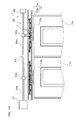
- FIG. 1 is a front view showing a door apparatus 2 according to one embodiment of the present invention.
- the door apparatus 2 shown in FIG. 1 can be used, for example, for a side wall of a railroad vehicle as a structure.
- FIG. 1 shows a front view of the door apparatus 2, as viewed from the inside of the railroad vehicle.
- illustration of the side wall of the railroad vehicle is omitted in FIG. 1 , and the door apparatus 2 is schematically illustrated.
- the door apparatus 2 includes door hanging apparatuses 1 according to one embodiment of the present invention, doors 11 (partly shown in FIG. 1 ), an open-close drive mechanism 12, and so forth.
- the doors 11 are formed as sliding doors provided at a side wall of a railroad vehicle (hereinafter, referred to as a "structure"), are installed along the vertical direction, and constitute side doors provided in the railroad vehicle for loading and unloading of passengers.
- a railroad vehicle hereinafter, referred to as a "structure"
- two doors namely, door 11a and a door 11b, are provided as the doors 11.
- the doors 11 (11a, 11b) are supported by the door hanging apparatuses 1, which will be described below, in a state in which it is suspended to the structure so as to be slidably moved.
- rails 13 of the door hanging apparatuses 1 are fixed to the structure in a state in which they are disposed extending linearly in the horizontal direction.
- the door 11a and the door 11b are supported by door roller mechanisms 14, which will be described below, of the respective door hanging apparatuses 1 at their upper ends, and are configured to be closed by approaching each other along the rail 13 and coming into contact and to be opened by moving away from each other.
- the open-close drive mechanism 12 is installed in the structure, and is provided as a mechanism that is connected to the door hanging apparatuses 1 and that drives the doors 11 (11a, 11b) to be opened and closed.
- the open-close drive mechanism 12 shown in FIG. 1 includes, for example, a drive motor (not shown), a drive pulley 15, a driven pulley 16, and a belt 17.
- the belt 17 is configured as an endless belt that is wound around the drive pulley 15 and the driven pulley 16 in a freely rotatable manner. Rotation of the drive pulley 15 connected to the drive motor causes the belt 17 wound around the drive pulley 15 to be rotated, thus causing the driven pulley 16 to rotate together with the belt 17.
- the drive motor is controlled to be rotated by a predetermined amount in forward and reverse directions, in accordance with a command from a controller, which is not shown. Accordingly, the doors 11 (11a, 11b) that are supported in a state in which they are suspended via the door hanging apparatuses 1 connected to the belt 17 of the open-close drive mechanism 12 are driven in the opening direction and the closing direction.
- FIG. 1 shows the state of a fully closed position in which the two doors 11 (11a, 11b) are closed
- FIG. 2 shows the state of a fully opened position in which the two doors 11 are opened.
- door roller mechanisms (14a, 14b), which will be described below, of the door hanging apparatuses 1 are moved in directions away from each other, and the state of the two doors 11 (11a, 11b) is shifted to the state of the fully opened position shown in FIG. 2 .
- the open-close drive mechanism 12 such that the belt 17 is rotated in the direction indicated by the arrow B shown in FIG. 2
- the door roller mechanisms (14a, 14b) are moved in directions approaching each other, and the state of the two doors 11 (11a, 11b) is shifted to the state of the fully closed position shown in FIG. 1 .
- a door hanging apparatus 1 includes a rail 13 and door roller mechanisms 14 (14a, 14b).
- FIG. 3 is a cross-sectional view of the rail 13, as viewed from the position of the arrows C-C in FIG. 2 .
- the rail 13 shown in FIGS. 1 to 3 is fixed to the structure and includes an upper rail 13a and a lower rail 13b that are respectively provided with vertically opposed running surfaces (18a, 18b).
- the upper rail 13a and the lower rail 13b extend linearly in the horizontal direction, and are formed integrally via a bridging portion 13c of the rail 13.
- the cross section of the running surface 18a of the upper rail 13a is formed so as to bulge downward in an arc shape
- the cross section of the running surface 18b of the lower rail 13b is formed so as to bulge upward in an arc shape and opposing the running surface 18a.
- the configuration of the rail 13 shown in FIGS. 1 to FIG. 3 is an example, and various modifications can be made to the cross-sectional shape of the rail 13.
- the cross section may be formed so as to be recessed in an arc shape.
- the upper rail 13a and the lower rail 13b do not need to be integrally formed. That is, the upper rail 13a and the lower rail 13b may be formed and disposed separately, or may be formed as separate parts and coupled to each other via another member.
- the door roller mechanisms 14 (14a, 14b) are provided in one-to-one correspondence with the doors (11a, 11b), and are each connected to the belt 17 of the open-close drive mechanism 12. Also, the door roller mechanism 14a supports the door 11a in a state in which the door 11a is suspended to the structure so as to be slidably moved, and the door roller mechanism 14b supports the door 11b in a state in which the door 11b is suspended to the structure so as to be slidably moved.
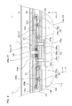
- FIG. 4 is a front view showing the door roller mechanism 14a shown in FIG. 1 , showing, in enlargement, a part of FIG. 1 in a cutaway state.
- the door roller mechanism 14a includes a plurality of first door rollers (19, 20), a first door roller supporting member 21, a plurality of swing members (22, 23), a plurality of second door rollers (24, 25), a drive connection portion 26, an elastic connection mechanism 27, a hanger 28, and so forth.
- the door roller mechanism 14a which is disposed on the driven pulley 16 side and connected to the door 11a, is shown in FIG. 4 .
- the door roller mechanism 14b which is disposed on the drive pulley 15 side and connected to the door 11b, is configured in the same manner, except that its devices are arranged line-symmetric about the intermediate position between the two doors 11 with respect to the devices of the door roller mechanism 14a and that the drive connection portion 26 has a different length. Therefore, only the door roller mechanism 14a will be described in the following.
- FIG. 5 is a cross-sectional view of the rail 13, as viewed from the position of the arrows D-D in FIG. 4 , and shows the first door rollers 19 and the second door rollers 24 together. Note that illustration of the elements other than the rail 13, the first door rollers 19 and the second door rollers 24 is omitted in FIG. 5 . As shown in FIGS. 4 and 5 , the first door rollers (19, 20) are provided as door rollers that run in contact with the running surface 18b of the lower rail 13b.
- first door rollers (19, 20) are disposed in positions that are substantially line-symmetric about an imaginary center line (hereinafter, referred to as the "center line of the door roller mechanism 14a") extending vertically through the central position of the door roller mechanism 14a in a direction parallel to the lengthwise direction of the rail 13.
- center line of the door roller mechanism 14a an imaginary center line
- Door trailing end-side first door rollers 19 and door leading end-side first door rollers 20 are provided as the first door rollers (19, 20).
- the door trailing end-side first door rollers 19 (19a, 19b) are disposed on a door trailing end side, which is the side on which the end of the door in an opening direction (the direction indicated by the arrow E in FIG. 4 ) is located, with respect to the center line of the door roller mechanism 14a.
- a plurality of (in this embodiment, two) door trailing end-side first door rollers 19 are provided, and a door trailing end-side first door roller 19b and a door trailing end-side first door roller 19a are arranged in order from the center line of the door roller mechanism 14a toward the door trailing end side.
- the door leading end-side first door rollers 20 (20a, 20b) are disposed on a door leading end side, which is the side on which the end of the door in the closing direction (the direction indicated by the arrow F in FIG. 4 ) is located, with respect to the center line of the door roller mechanism 14a.
- a plurality of (in this embodiment, two) door leading end-side first door rollers 20 are provided, and a door leading end-side first door roller 20a and a door leading end-side first door roller 20b are arranged in order from the center line of the door roller mechanism 14a toward the door leading end side.
- the cross section of the first door rollers (19a, 19b, 20a, 20b) that is perpendicular to the door roller circumferential direction of the rolling surface that rolls on the running surface 18b of the lower rail 13b when the first door rollers run on the lower rail 13b is formed so as to be recessed in an arc shape in conformity with the running surface 18b (see FIG. 5 ).
- this embodiment has been described, taking, as an example, a door roller mechanism 14a provided with a plurality of door trailing end-side first door rollers 19 and a plurality of door leading end-side first door roller 20, this need not be the case. It is also possible to adopt a configuration in which a door trailing end-side first door roller 19 and a door leading end-side first door roller 20 are provided.
- the first door roller supporting member 21 is provided as a member that suspends the door 11a via the hanger 28 and rotatably supports the first door rollers (19, 20).
- this embodiment describes, as an example, a first door roller supporting member 21 including a member that supports the door trailing end-side first door rollers (19a, 19b), a member that supports the door leading end-side first door rollers (20a, 20b), and a member that fixes these two members at both ends and couples them integrally, and thereby all the members are coupled together to form a single shaft.
- the first door roller supporting member 21 is disposed parallel to the lengthwise direction of the rail 13.
- the door trailing end-side first door roller 19a is rotatably supported via an axle 31a
- the door trailing end-side first door roller 19b is rotatably supported via an axle 31b
- the door leading end-side first door roller 20b is rotatably supported via an axle 32b
- the door leading end-side first door roller 20a is rotatably supported via an axle 32a.
- the hanger 28 is provided as a mechanism for suspending the door 11a to the first door roller supporting member 21.
- the hanger 28 includes a door coupling member 28a that is coupled and fixed to the upper end of the door 11a, and attachment members (28b, 28c) that are fixed above the door coupling member 28a and are attached to the first door roller supporting member 21.
- the attachment members (28b, 28c) are attached to the first door roller supporting member 21 in opposite positions across the center line of the door roller mechanism 14a. Further, the attachment members (28b, 28c) are pivotably attached to the first door roller supporting member 21 via a hinge portion, in a state in which their relative movements with respect to each other in a direction parallel to the lengthwise direction of the rail 13 are restricted.
- the hanger 28 causes the door 11a to move horizontally together with the first door roller supporting member 21 in a state in which the door 11a is swingably supported to the first door roller supporting member 21.
- a plurality of (in this embodiment, two) swing members (22, 23) are provided, and each of the swing members is formed as a shaft-like member and swingably connected to the first door roller supporting member 21.
- a door trailing end-side swing member 22 connected to the first door roller supporting member 21 on the door trailing end side and a door leading end-side swing member 23 connected to the first door roller supporting member 21 on the door leading end side are provided as the swing members (22, 23).
- the door trailing end-side swing member 22 is rotatably connected, at one end thereof, to the door trailing end-side end of the first door roller supporting member 21, coaxially with the axle 31a.
- the door leading end-side swing member 23 is rotatably connected, at one end thereof, to the door leading end-side end of the first door roller supporting member 21, coaxially with the axle 32b.
- the door trailing end-side swing member 22 may be rotatably connected to the first door roller supporting member 21 via a rotational shaft disposed parallel to the axles (31a, 31b) between a plurality of door trailing end-side first door rollers (19a, 19b).
- the door leading end-side swing member 23 may be rotatably connected to the first door roller supporting member 21 via a rotational shaft disposed parallel to the axles (32a, 32b) between a plurality of door leading end-side first door rollers (20a, 20b).
- the second door rollers (24, 25) are provided as door rollers that are rotatably supported to the swing members (22, 23) and disposed so as to be capable of coming into contact with the upper rail 13a. Also, the second door rollers (24, 25) are disposed in positions that are substantially line-symmetric about the center line of the door roller mechanism 14a, and are provided on both the door trailing end side and the door leading end side with respect to an elastic connection mechanism 27, which will be described below.
- a door trailing end-side second door roller 24 disposed on the door trailing end side with respect to the center line of the door roller mechanism 14a and a door leading end-side second door roller 25 disposed on the door leading end side with respect to the center line of the door roller mechanism 14a are provided as the second door rollers (24, 25).
- the door trailing end-side second door roller 24 is rotatably supported via the axle 33a to the door trailing end-side swing member 22 at the other end of the door trailing end-side swing member 22, which is opposite to an end thereof connected to the first door roller supporting member 21.
- the door leading end-side second door roller 25 is rotatably supported via the axle 33b to the door leading end-side swing member 23 at the other end of the door leading end-side swing member 23, which is opposite to an end thereof connected to the first door roller supporting member 21.
- the door trailing end-side second door roller 24 is disposed further toward the door trailing end side than the door trailing end-side first door roller 19a, which is the first door roller that is disposed closest to the door trailing end side in the door roller mechanism 14a.
- the door leading end-side second door roller 25 is disposed further toward the door leading end side than the door leading end-side first door roller 20b, which is the first door roller disposed closest to the door leading end side in the door roller mechanism 14a.
- the second door rollers (24, 25) are disposed via a slight gap from, or disposed in slight contact with the running surface 18a of the upper rail 13a on the upper end side thereof, in a state in which the first door rollers (19, 20) are not running on the lower rail 13b (i.e., in a state in which the first door roller mechanism 14a is stationary with respect to the structure).
- the cross section of the second door rollers (24, 25) that is perpendicular to the door roller circumferential direction of the rolling surface that rolls on the running surface 18a of the upper rail 13a when the door roller mechanism 14a is moved horizontally along the rail 13 is formed so as to be recessed in an arc shape in conformity with the running surface 18a.
- FIGS. 6 are enlarged views showing the cross section of a side face of a second door roller 24 and the rail 13.
- FIG. 6(a) is a diagram showing a state in which the second door roller 24 is disposed via a slight gap from the upper rail 13a or disposed in a position where it is in light contact with the upper rail 13a (the state according to this embodiment)
- FIG. 6(b) is a diagram showing a state in which the second door roller 24 is disposed via a gap within an predetermined range from the rail 13a.
- the riding width which is the vertical spacing (width) between the lower end portion of the upper rail 13a and the upper end portion of the second door roller 24 in a state in which the lower end portion of the upper rail 13a and the upper end portion of the second door roller 24 are disposed overlapping each other in the horizontal direction, is the width dimension indicated by the double-ended arrow G1 in the drawing. That is, it is the width dimension between the lower end portion of the running surface 18a and a portion of the second door roller 24 that is located at the upper end of both edges 24b of the rolling surface 24a.
- the running surface 18a of the upper rail 13a and the rolling surface 24a of the second door roller 24 oppose each other via a gap having a dimension indicated by the double-ended arrow H in the drawing.
- the second door roller 24 is disposed such that the height position of a portion located at the upper end of the both edges 24b of the second door roller 24 is located above the height position (the position in the vertical direction) of the lower end portion of the running surface 18a opposing the central portion of the rolling surface 24a via a gap having a predetermined size.
- a riding width having the width dimension indicated by the double-ended arrow G2 in the drawing is secured as the riding width between the upper rail 13a and the second door roller 24.
- the second door roller (24, 25) may be disposed via a gap within a predetermined range, which is the range in which a riding width can be secured, from the upper rail 13a.
- the drive connection portion 26 is provided as a member for holding and connecting the door 11a to the open-close drive mechanism 12.
- the drive connection portion 26 is fixed to the belt 17 at its end on the upper end side, and is connected to an elastic connection mechanism 27, which will be described below, on the lower end side. Thereby, the drive connection portion 26 holds and connects the door 11a to the belt 17 via the elastic connection mechanism 27, the swing members (22, 23), the first door roller supporting member 21, and the hanger 28.
- a through hole extending parallel to the lengthwise direction of the rail 13 is formed in the end of the drive connection portion 26 on the lower end side, and the central part of the first door roller supporting member 21 is disposed passing through the through hole in a state in which it is loosely fitted so as to be swingable and pivotable. Accordingly, when the first door roller supporting member 21 is relatively displaced with respect to the drive connection portion 26, the direction of relative displacement of the first door roller supporting member 21 can be restricted so as to be guided in a direction parallel to the direction of movement of the drive connection portion 26. Thereby, the movement of the door 11a, which is connected to the first door roller supporting member 21 via the hanger 28, can be further restricted to a sliding movement in a plane parallel to the plane in which the upper and lower rails (13a, 13b) are disposed.
- the elastic connection mechanism 27 is provided as a mechanism for elastically connecting the swing members (22, 23) to the drive connection portion 26, and includes a pair of spring members (30a, 30b) and a swingable connection member 29.
- the pair of spring members (30a, 30b) constitute an elastic portion of this embodiment that is capable of changing the relative position between the second door rollers (24, 25) and the drive connection portion 26 by elastic deformation.
- the pair of spring members (30a, 30b) are provided as coil springs, and are disposed on opposite sides in a direction along the lengthwise direction of the rail 13 with respect to the drive connection portion 26. Note that the spring member 30a is disposed on the door trailing end side with respect to the drive connection portion 26, and the spring member 30b is disposed on the door leading end side with respect to the drive connection portion 26.
- the swingable connection member 29 is provided as a shaft-like member that is connected to the drive connection portion 26 via the pair of spring members (30a, 30b) such that its relative position with respect to the drive connection portion 26 can be changed.
- An end of the door trailing end-side swing member 22 and an end of the door leading end-side swing member 23 are rotatably connected respectively at opposite ends of the swingable connection member 29.
- the swingable connection member 29 is disposed passing through the through hole that is formed in the drive connection portion 26 so as to extend parallel to the lengthwise direction of the rail 13, and the swingable connection member 29 passes through the inside of the spring members (30a, 30b), which are provided as coil springs, on opposite sides of the drive connection portion 26.
- the swingable connection member 29 is disposed slidably passing through the through hole of the drive connection portion 26 in a state in which it is freely fitted so as to allow a predetermined tilting.
- the pair of spring members (30a, 30b) are disposed so as to bias the drive connection portion 26 in opposite directions from opposite sides in a passing-through direction, in which the swingable connection member 29 passes through the drive connection portion 26.
- the ends of the spring members (30a, 30b) that are opposite to the ends that bias the drive connection portion 26 are respectively supported to collar portions (29a, 29b) that are formed in the swingable connection member 29 and disposed on opposite sides of the drive connection portion 26.
- the spring members (30a, 30b) may be provided as tension springs that apply biasing forces in directions in which they pull against each other via the drive connection portion 26, or may be provided as compression springs that apply biasing forces in directions in which they press against each other via the drive connection portion 26.
- the spring members (30a, 30b) are provided as tension springs, opposite ends of each of the spring members (30a, 30b) need to be fixed to the drive connection portion 26 and the collar portions (29a, 29b).
- opposite ends of each of the spring members (30a, 30b) may be either fixedly supported to or supported in contact with the drive connection portion 26 and the collar portions (29a, 29b).
- connection position between the swingable connection member 29 and the door trailing end-side swing member 22 are disposed on the side of the second door roller 24 supported to the door trailing end side swing member 22 with respect to the connection position between the door trailing end side swing member 22 and the first door roller supporting member 21.
- the swingable connection member 29 and the door trailing end-side swing member 22 are rotatably connected coaxially with the axle 33a via which the second door roller 24 is rotatably supported to the door trailing end-side swing member 22.
- connection position between the swingable connection member 29 and the door leading end-side swing member 23 is disposed on the side of the second door roller 25 supported to the door leading end-side swing member 23 with respect to the connection position between the door leading end-side swing member 23 and the first door roller supporting member 21.
- the swingable connection member 29 and the door leading end-side swing member 23 are rotatably connected coaxially with the axle 33b via which the second door roller 25 is rotatably supported to the door leading end-side swing member 23.
- the door trailing end-side swing member 22 is rotatably connected to the first door roller supporting member 21, the swingable connection member 29 is rotatably connected to the door trailing end-side swing member 22, the door leading end-side swing member 23 is rotatably connected to the swingable connection member 29, and the first door roller supporting member 21 is rotatably connected to the door leading end-side swing member 23.
- the door roller mechanism 14a includes the first door roller supporting member 21, the door trailing end-side swing member 22, the swingable connection member 29, and the door leading end-side swing member 23, which are provided as four links, and these links constitute a quadrangular link mechanism.
- the door roller mechanisms (14a, 14b) are moved in directions in which they move away from each other by the open-close drive mechanism 12 operating in the state shown in FIG. 1 , and thereby, the doors (11a, 11b) respectively suspended to the door roller mechanisms (14a, 14b) are opened as shown in FIG. 2 .
- the door roller mechanisms (14a, 14b) are moved in directions in which they approach each other by the drive motor of the open-close drive mechanism 12 rotating in a direction opposite to the aforementioned opening operation in the state shown in FIG. 2 , and thereby the doors (11a, 11b) are closed as shown in FIG. 1 .
- the door roller mechanism 14a and the door roller mechanism 14b respectively cause the door 11a and the door 11b to slidably move in the opening and closing direction along the lengthwise direction of the rail 13 via operation of the open-close drive mechanism 12.
- the door roller mechanism 14a and the door roller mechanism 14b operate in the same manner in states line-symmetric about the intermediate position of the two doors 11, and therefore, only the operation of the door roller mechanism 14a will be described in the following.
- FIG. 7 is a front view schematically showing the door roller mechanism 14a, together with part of the upper and lower rails (13a, 13b) and the door 11a, and schematically shows the first door roller supporting member 21, the door trailing end-side swing member 22, the swingable connection member 29, and the door leading end-side swing member 23 by the dashed line.
- the relative positional state of the swingable connection member 29 and the swing members (22, 23) with respect to the door 11a is changed by elastic deformation of the pair of spring members (30a, 30b).
- the directions of several forces acting on the door roller mechanism 14a when a foreign object has collided with the end of the door 11a on the door leading end side during the closing operation of the door 11a are indicated by the arrows (K1 to 6) in FIG. 7 .
- forces in the same directions as the directions indicated by the arrows in FIG. 7 act on the door roller mechanism 14a during the acceleration operation, and therefore, the description thereof has been omitted.
- forces in directions opposite to the directions indicated by the arrows shown in FIG. 7 act on the door roller mechanism 14a during the deceleration operation, and the forces simply act in states line-symmetric with the door roller mechanism 14a during the acceleration operation. Therefore, the description thereof has been omitted.
- the door trailing end-side swing member 22 is displaced so as to swing in a direction (the direction indicated by the arrow K3 in the drawing) in which it swings upward, with the door trailing end-side first door roller 19a as the center. Furthermore, the door trailing end-side second door roller 24 is displaced upward (in the direction indicated by the arrow K4 in the drawing) and thus comes into contact with the upper rail 13a, which results in an increase in the contact pressure between the upper rail 13a and the second door roller 24.
- the door trailing end-side second door roller 24 is displaced, and at the same time, the swingable connection member 29 is relatively displaced toward the door leading end side with respect to the drive connection portion 26 by elastic deformation of the pair of springs (30a, 30b).
- the door leading end-side swing member 23 is displaced so as to swing in a direction (the direction indicated by the arrow K5 in the drawing) in which it swings downward, with the door leading end-side first door roller 19b as the center.
- the door leading end-side second door roller 25 is displaced downward (in the direction indicated by the arrow K6 in the drawing) and thus is moved away from the upper rail 13b.
- the pair of spring members (30a, 30b) elastically deform such that they deform in opposite directions to each other.
- the four links (21, 22, 29, 23) are relatively displaced with respect to the door 11a by elastic deformation of the pair of spring members (30a, 30b).
- the positions of the second door rollers (24, 25) with respect to the upper rail 13a are positioned in suitable positions according to the above-described load. Note that the amounts of displacement of the four links (21, 22, 29, 23) and the first and second door rollers (19, 20) described above are within a range that is allowable in the space between the upper and lower rails (13a, 13b).
- the first door rollers (19, 20) and the second door rollers (24, 25) that are disposed between the upper and lower rails (13a, 13b) and run thereon constitute a derailing prevention mechanism, and therefore, it is possible to reliably prevent the derailing of the door rollers (19, 20, 24, 25) and the tilting of the doors 11 (11a, 11b) when the doors 11 (11a, 11b) are opened and closed.
- the elastic connection mechanism 27 that connects the drive connection portion 26 for connecting the doors 11 (11a, 11b) to the open-close drive mechanism 12 and the swing members (22, 23) includes the pair of spring members (30a, 30b) serving as an elastic portion, and the elastic connection mechanism 27 is provided so as to be capable of changing the relative position between the second door rollers (24, 25) and the drive connection portion 26 by elastic deformation.
- the swingable connection member 29 and the swing members (22, 23) are relatively displaced with respect to the doors 11 (11a, 11b) by the elastic deformation of the pair of spring members (30a, 30b), and the contact pressure exerted on the upper rail 13a from the second door rollers (24, 25) is temporarily increased.
- the elastic deformation of the pair of spring members (30a, 30b) is immediately restored when the velocity is constant, and consequently, the distance relationship between the upper rail 13a and the second door rollers (24, 25) is brought back to the original state.
- the swingable connection member 29 and the swing members (22, 23) are relatively displaced with respect to the doors 11 (11a, 11b) by elastic deformation of the pair of spring members (30a, 30b), and the positions of the second door rollers (24, 25) with respect to the upper rail 13a are positioned in suitable positions according to the above-described load.
- the second door rollers (24, 25) are disposed in light contact with the upper rail 13a or disposed so as to provide a gap within a predetermined range that can secure a riding width between the upper rail 13a and the second door rollers (24, 25), and thereby, it is possible to set a state in which little running resistance is generated in a derailing prevention mechanism when the door rollers (19, 20, 24, 25) are running on the rail 13.
- the door rollers (19, 20, 24, 25) can be positioned in suitable positions according to the load, and the derailing of the door rollers (19, 20, 24, 25) and the tilting of the doors 11 (11a, 11b) can be reliably prevented.
- the positional adjustment of the second door rollers (24, 25) namely, the degree to which the second door rollers (24, 25) is in contact with the upper rail 13a or the amount of the gap provided within a predetermined range, has little impact on the above-described derailing prevention performance. Accordingly, the positional adjustment requires little time and effort at the time of installing the door hanging apparatus 1, and the installation operation can be performed easily.
- a door hanging apparatus 1 and a door apparatus 2 that can reliably prevent the derailing of door rollers (19, 20, 24, 25) and the tilting of doors 11 (11a, 11b) when the doors 11 (11a, 11b) are opened and closed, while having little running resistance caused by a derailing prevention mechanism.
- the second door rollers (24, 25) are provided on both the door leading end side and the door trailing end side with respect to the elastic connection mechanism 27. Accordingly, both during the opening driving and the closing driving of the doors 11 (11a, 11b), the positions of the second door rollers (24, 25) with respect to the upper rail 13a can be positioned in suitable positions via operation of the elastic connection mechanism 27 at the time of the acceleration/deceleration or when a foreign object has collided with the end of the doors.
- the door leading end-side and door trailing end-side swing members (22, 23) are respectively connected to opposite sides of the first door roller supporting member 21 that supports the first door rollers (19, 20), and the swingable connection member 29 of the elastic connection mechanism 27 is further connected thereto so as to connect the two swing members (22, 23), thus constituting a quadrangular link mechanism having fours links.
- connection position with the swingable connection member 29 is disposed on the side of the door trailing end-side second door roller 24 with respect to the connection position with the first door roller supporting member 21. Accordingly, when the connection position with the swingable connection member 29 is disposed in a position closer to the connection position with the first door roller supporting member 21, the response performance of the door trailing end-side second door roller 24 via the door trailing end-side swing member 22 via operation of the elastic connection mechanism 27 can be set to be faster, which makes it possible to more quickly position the door trailing end-side second door roller 24 in a suitable position.
- connection position with the swingable connection member 29 when the connection position with the swingable connection member 29 is disposed in a position farther away from the connection position with the first door roller supporting member 21, a greater force can be easily secured as the force exerted on the upper rail 13a from the door trailing end-side second door roller 24 via the door trailing end-side swing member 22 via operation of the elastic connection mechanism 27. Consequently, by simply changing the connection position with the swingable connection member 29 with respect to the connection position with the first door roller supporting member 21 for the door trailing end-side swing member 22, it is possible to easily adjust the setting of the response performance of the door trailing end-side second door roller 24 via operation of the elastic connection mechanism 27 and the setting of the force exerted on the upper rail 13a from the door trailing end-side second door roller 24.
- the swingable connection member 29 and the door trailing end-side swing member 22 are rotatably connected coaxially with the axle 33a of the door trailing end-side second door roller 24, and therefore, the same shaft can be used as the axle 33a of the door trailing end-side second door roller 24 and the rotational shaft of the swingable connection member 29 and the door trailing end-side swing member 22. Accordingly, it is possible to reduce the number of members, which makes is possible to further increase the compactness of the structure.
- connection position with the swingable connection member 29 is disposed on the side of the door leading end-side second door roller 25 with respect to the connection position with the first door roller supporting member 21. Accordingly, when the connection position with the swingable connection member 29 is disposed in a position closer to the connection position with the first door roller supporting member 21, the response performance of the door leading end-side second door roller 25 via the door leading end-side swing member 23 via operation of the elastic connection mechanism 27 can be set to be faster, which makes it possible to more quickly position the door leading end-side second door roller 25 in a suitable position.
- connection position with the swingable connection member 29 when the connection position with the swingable connection member 29 is disposed in a position farther away from the connection position with the first door roller supporting member 21, a greater force can be easily secured as the force exerted on the upper rail 13a from the door leading end-side second door roller 25 via the door leading end-side swing member 23 via operation of the elastic connection mechanism 27. Consequently, by simply changing the connection position with the swingable connection member 29 with respect to the connection position with the first door roller supporting member 21 for the door leading end-side swing member 23, it is possible to easily adjust the setting of the response performance of the door leading end-side second door roller 25 via operation of the elastic connection mechanism 27 and the setting of the force exerted on the upper rail 13a from the door leading end-side second door roller 25.
- the swingable connection member 29 and the door leading end-side swing member 23 are rotatably connected coaxially with the axle 33b of the door leading end-side second door roller 25, and therefore, the same shaft can be used as the axle 33b of the door leading end-side second door roller 25 and the rotational shaft of the swingable connection member 29 and the door leading end-side swing member 23. Accordingly, it is possible to reduce the number of members, which makes is possible to further increase the compactness of the structure.
- the respective ends of the pair of spring members (30a, 30b) are supported to the swingable connection member 29 and the drive connection portion 26 is biased by the pair of spring members (30a, 30b) in opposite directions, and thereby the elastic connection mechanism 27 can be easily constructed with a simple structure.
- the link mechanism formed by the first door roller supporting member, the swing members, and the swingable connection member is a quadrangular link mechanism constituted by four links, this need not be the case. That is, the link mechanism formed by the first door roller supporting member, the swing members, and the swingable connection member may be a link mechanism constituted by five or more links.
- the number of the first door rollers and the second door rollers provided in the door roller mechanism is not limited to those illustrated in this embodiment, and various modifications may be made. Although this embodiment has been described, taking, as an example, a configuration in which a second door roller is rotatably connected each of the swing members, this need not be the case. That is, it is sufficient to provide a second door roller that is rotatably supported to at least one of a plurality of swing members.
- FIGS. 8 are schematic diagrams illustrating modifications in which the swingable connection member and the door trailing end-side swing member are connected at a position offset from the axle of the door trailing end-side second door roller, and schematically show part of the first door roller supporting member 21 and the swingable connection member 29, the door trailing end-side swing member 22, the door trailing end-side first door rollers (19a, 19b), and the door trailing end-side second door roller 24.
- the swingable connection member and the door leading end-side swing member are also connected in a position offset from the axle of the door leading end-side second door roller.
- the response performance of the door trailing end-side second door roller 24 can be set to be faster, compared to the case where the connection position between the swingable connection member 29 and the door trailing end-side swing member 22 is provided coaxially with the axle 33a.
- the position of a rotational shaft 35 that rotatably connects the swingable connection member 29 to the door trailing end-side swing member 22, or in other words, the connection position between the swingable connection member 29 and the door trailing end-side swing member 22 is provided in a position farther away from the axle 33a of the door trailing end-side second door roller 24 toward the door trailing end side with respect to the connection position between the door trailing end-side swing member 22 and the first door roller supporting member 21.
- the axle 33a of the door trailing end-side second door roller 24 is provided in a position between the connection position between the door trailing end-side swing member 22 and the first door roller supporting member 21 and the connection position between the swingable connection member 29 and the door trailing end-side swing member 22.
- a greater force can be easily secured as the force exerted on the upper rail 13a from the door trailing end-side second door roller 24, compared to the case where the connection position between the swingable connection member 29 and the door trailing end-side swing member 22 is provided coaxially with the axle 33a.
- FIGS. 9 to 11 are front views respectively showing a door apparatus 3, a door apparatus 4, and a door apparatus 5 according to modifications in which open-close drive mechanisms different from that of this embodiment are provided, and the drawings correspond to FIG. 1 of this embodiment. Note that the description of those elements of the door apparatuses (3, 4, 5) shown in FIGS. 9 to 11 that are configured in the same manner as the door apparatus 2 of this embodiment are denoted by the same reference numerals in the drawings, and the description thereof has been omitted.
- an open-close drive mechanism 40 includes a drive motor (not shown), a pinion 41, an upper rack 42, a lower rack 43, and so forth.
- the pinion 41 is connected to the drive motor, and is rotationally driven with rotation of the drive motor.
- the pinion 41 is disposed so as to be meshed with the upper rack 42 that is disposed thereabove so as to extend horizontally and the lower rack 43 that is disposed therebelow so as to extend horizontally
- the upper rack 42 and the lower rack 43 are supported to the structure so as to be slidably moved, parallel to the lengthwise direction of a rail 13.
- the upper rack 42 and the lower rack 43 are configured to be slidably moved in opposite directions to each other by rotation of the pinion 41.
- the upper rack 42 is connected to a door roller mechanism 14b that supports a door 11b in a suspended state
- the lower rack 43 is connected to a door roller mechanism 14a that supports a door 11a in a suspended state. Accordingly, rotations of the pinion 41 with a forward operation and a reverse operation of the drive motor cause the doors 11 (11a, 11b) to be driven to be moved in the opening direction and the closing direction.
- an open-close drive mechanism 50 includes a drive motor 51, a screw shaft 52, a rotation receiving portion 53, nut members (54a, 54b), and so forth.
- the screw shaft 52 is connected to the drive motor 51 at its one end, and is rotatably supported by the rotation receiving portion 53 at the other end. Accordingly, the screw shaft 52 is rotationally driven with rotation of the drive motor 51.
- an externally threaded portion 52a formed from the center portion to one end and an externally threaded portion 52b formed from the center portion to the other end are formed as threaded portions in reverse directions.
- the nut members (54a, 54b) are provided as members that are threadedly engaged with the screw shaft 52 and are connected to the door hanging apparatus 1.
- the nut member 54a is threadedly engaged with one of the externally threaded portions of the screw shaft 52, namely the externally threaded portion 52a, and is connected to a door roller mechanism 14a that supports a door 11a in a suspended state.
- the nut member 54b is threadedly engaged with the other externally threaded portion of the screw shaft 52, namely the externally threaded portion 52b, and is connected to a door roller mechanism 14b that supports a door 11b in a suspended state.
- an open-close drive mechanism 60 includes a drive motor 61, screw shafts (62a, 62b), rotation receiving portions (63a, 63b, 63c), gear portions (64a, 64b), nut members (65a, 65b), and so forth.
- the screw shaft 62a is connected to the drive motor 61 at its one end, and is rotatably supported by the rotation receiving portion 63a at the other end. Accordingly, the screw shaft 62a is rotationally driven with rotation of the drive motor 61.
- the screw shaft 62b has a threaded portion formed therein in the same direction as that of the screw shaft 62a, and is rotatably supported by the rotation receiving portions (63b, 63c) at opposite ends.
- the gear portion 64a having teeth of a spur gear formed on its outer circumference is fixed coaxially to the screw shaft 62a.
- the gear portion 64b having teeth of a spur gear formed on its outer circumference and meshing with the gear portion 64a is fixed coaxially to the screw shaft 62b.
- the nut member 65a is provided as a member that is threadedly engaged with the screw shaft 62b and is connected to a door roller mechanism 14a that supports a door 11a in a suspended state.
- the nut member 65b is provided as a member that is threadedly engaged with the screw shaft 62a and is connected to a door roller mechanism 14b that supports a door 11b in a suspended state.
- the present invention is widely applicable as a door hanging apparatus that supports a door provided in a structure and driven to be opened and closed by an open-close drive mechanism, in a state in which the door is suspended to the structure so as to be slidably moved, and that is connected to the open-close drive mechanism, and a door apparatus provided with the door hanging apparatus.
Landscapes
- Engineering & Computer Science (AREA)
- Mechanical Engineering (AREA)
- Power-Operated Mechanisms For Wings (AREA)
- Support Devices For Sliding Doors (AREA)
Abstract
Description
- The present invention relates to a door hanging apparatus that supports a door provided in a structure and driven to be opened and closed by an open-close drive mechanism, in a state in which the door is suspended to the structure so as to be slidably moved, and that is connected to the open-close drive mechanism, and a door apparatus provided with the door hanging apparatus.
- Conventionally, door hanging apparatuses that support a door provided in a structure and driven to be opened and closed by an open-close drive mechanism, in a state in which the door is suspended to the structure so as to be slidably moved, and that is connected to the open-close drive mechanism are known (for example, see Patent Document 1). As a door hanging apparatus used in a railroad vehicle serving as a structure,
Patent Document 1 discloses a door hanging apparatus including a rail member including an upper rail and a lower rail, and a door roller device including door rollers that run on the rail member. Also, inPatent Document 1, a door that is suspended to the door hanging apparatus is driven to be opened and closed by an open-close drive mechanism connected to the door hanging apparatus, and the door is supported in a state of being suspended to the structure, which is a side wall of the railroad vehicle, so as to be slidably moved. - Further, the door roller device of the above-described door hanging apparatus is provided with a supporting member disposed along the lengthwise direction of the rail member, and this supporting member is provided with a first door roller capable of running on the lower rail and a second door roller capable of running on the upper rail. The second door roller is provided at one end of the supporting member, and a suspender capable of suspending the door is provided on the other end of the supporting member. Accordingly, the self weight of the door acts on the suspender, the second door roller comes into contact with the upper rail with the first door roller, which runs on the lower rail, serving as a fulcrum, and thereby, the door is supported. Accordingly, it is possible to provide a door hanging apparatus that can prevent the derailing of doors from a rail member, enable smooth and safe opening and closing of doors, and achieve a reduction in manufacturing and installation costs.
-
- Patent Document 1:
WO2008/149632 - With the door hanging apparatus disclosed in
Patent Document 1, a mechanism is provided that prevents the derailing of the door rollers from the rail by causing the self weight of the door to exert the load for pressing the second door roller against the upper rail with the first door roller running on the lower rail as a fulcrum, and therefore, it is also possible to prevent the tilting of the door. However, with the door hanging apparatus ofPatent Document 1, the second door roller runs on the upper rail while being constantly pressed against the upper rail at a certain degree of contact pressure due to the load acting with the first door roller as a fulcrum, exerted by the self weight of the door. Accordingly, when the door rollers are running on the rail, a specific running resistance is generated in the derailing prevention mechanism, which results in a reduction in the driving efficiency of the open-close drive mechanism when driving the doors to be opened and closed. Further, the generation of running resistance may promote wear of the door rollers. - In view of the above-described circumstances, it is an object of the present invention to provide a door hanging apparatus that can reliably prevent the derailing of door rollers and the tilting of a door when the door is opened and closed, while having little running resistance caused by a derailing prevention mechanism, and also to provide a door apparatus provided with the door hanging apparatus.
- A door hanging apparatus of a first aspect of of the present invention for achieving the above-described objects relates to a door hanging apparatus that supports a door provided in a structure and driven to be opened and closed by an open-close drive mechanism, in a state in which the door is suspended to the structure so as to be slidably moved, and that is connected to the open-close drive mechanism. The door hanging apparatus of the first aspect of the invention includes: a rail including an upper rail and a lower rail that are fixed to the structure and are provided with respective running surfaces opposing each other in the vertical direction; a first door roller that runs in contact with the running surface of the lower rail; a first door roller supporting member that suspends the door and rotatably supports the first door roller; a plurality of swing members that are swingably connected to the first door roller supporting member; a second door roller that is rotatably supported to at least one of the swing members and is provided so as to be capable of coming into contact with the running surface of the upper rail; a drive connection portion for holding and connecting the door to the open-close drive mechanism; and an elastic connection mechanism that includes an elastic portion capable of changing a relative position between the second door roller and the drive connection portion by elastic deformation and connects the swing members to the drive connection portion.
- According to this aspect of the invention, the first door roller supported to the first door roller supporting member that suspends the door runs on the lower rail, and the second door roller supported to the swing members that are swingably connected to the first door roller supporting member are disposed so as to be capable of coming into contact with the upper rail. Accordingly, the first door roller and the second door roller that are disposed between the upper and lower rails and run thereon constitute a derailing prevention mechanism, and therefore, it is possible to reliably prevent the derailing of the door rollers and the tilting of the door when the door is opened and closed.
- Furthermore, according to the present invention, the elastic connection mechanism that connects the drive connection portion for connecting the door to the open-close drive mechanism and the swing members includes an elastic portion, and the elastic connection mechanism is provided so as to be capable of changing the relative position between the second door roller and the drive connection portion by elastic deformation. Accordingly, at the time of acceleration when the door is driven to be opened and closed, the elastic connection mechanism and the swing members are relatively displaced with respect to the door by the elastic deformation of the elastic portion, and the contact pressure exerted on the upper rail from the second door roller is temporarily increased. However, the elastic deformation of the elastic portion is immediately restored when the velocity is constant, and consequently, the distance relationship between the upper rail and the second door roller is brought back to the original state. Further, even if a load is exerted from the door as the result of a foreign object having collided with or having been caught at the end of the door in the opening and closing direction, the elastic connection mechanism and the swing members are relatively displaced with respect to the door by elastic deformation of the elastic portion, and the position of the second door roller with respect to the upper rail is positioned in a suitable position according to the above-described load.
- Therefore, according to the present invention, the second door roller is disposed in light contact with the upper rail or disposed so as to provide a gap within a predetermined range, and thereby, it is possible to set a state in which little running resistance is generated in a derailing prevention mechanism when the door rollers are running on the rail. Also, at the time of the acceleration/deceleration of the door or the collision with a foreign object, the door rollers can be positioned in suitable positions according to the load, and the derailing of the door rollers and the tilting of the door can be reliably prevented. Note that the gap within a predetermined range as used herein refers to a gap within a range that can secure a riding width, which is a vertical spacing (width) between the lower end portion of the upper rail and the upper end portion of the second door roller in a state in which the lower end portion of the upper rail and the upper end portion of the second door roller are disposed overlapping each other in the horizontal direction. Further, the positional adjustment of the second door roller, namely, the degree to which the second door roller is in contact with the upper rail or the amount of the gap provided within a predetermined range, has little impact on the above-described derailing prevention performance. Accordingly, the positional adjustment requires little time and effort at the time of installing the door hanging apparatus of the present invention, and the installation operation can be performed easily.
- Therefore, according to the present invention, it is possible to provide a door hanging apparatus that can reliably prevent the derailing of door rollers and the tilting of doors when the doors are opened and closed, while having little running resistance caused by a derailing prevention mechanism.
- According to a door hanging apparatus of a second aspect of the present invention, in the door hanging apparatus of the first aspect of the present invention, the second door roller is provided on both a door leading end side, which is the side on which the end of the door in a closing direction is located, and a door trailing end side, which is the side on which the end of the door in an opening direction is located, with respect to the elastic connection mechanism.
- According to this aspect of the invention, the second door roller is provided on both the door leading end side and the door trailing end side with respect to the elastic connection mechanism. Accordingly, both during the opening driving and the closing driving of the door, the position of the second door roller with respect to the upper rail can be positioned in a suitable position via operation of the elastic connection mechanism at the time of acceleration/deceleration or when a foreign object has collided with the end of the door. Accordingly, it is possible to achieve a door hanging apparatus that can reliably prevent the derailing of the door rollers and the tilting of the door, while having little running resistance caused by a derailing prevention mechanism, both during the opening driving and the closing driving of the door.
- According to a door hanging apparatus of a third aspect of the present invention, in the door hanging apparatus of the first or second aspect of the present invention, a door leading end-side swing member that is connected to the first door roller supporting member on the door leading end side and a door trailing end-side swing member that is connected to the first door roller supporting member on the door trailing end side are provided as the swing members, the elastic connection mechanism includes a swingable connection member that is connected to the drive connection portion via the elastic portion such that a relative position thereof with respect to the drive connection portion can be changed and to which the door leading end-side swing member and the door trailing end-side swing member are rotatably connected at opposite ends, respectively, and the first door roller supporting member, the door leading end-side swing member, the swingable connection member, and the door trailing end-side swing member, which are provided as four links, forms a quadrangular link mechanism.
- According to this aspect of the invention, the door leading end-side and door trailing end-side swing members are respectively connected to opposite sides of the first door roller supporting member that supports the first door roller, and the swingable connection member of the elastic connection mechanism is further connected thereto so as to connect the two swing members, thus constituting a quadrangular link mechanism having fours links. Accordingly, it is possible to construct, with a quadrangular link mechanism, a structure with a simple configuration that can position the position of the second door roller with respect to the upper rail in a suitable position via operation of the elastic connection mechanism in response to acceleration/deceleration of the door and the collision with a foreign object.
- According to a door hanging apparatus of a fourth aspect of the present invention, in the door hanging apparatus of the third aspect of the present invention, the second door roller is rotatably supported to the door leading end-side swing member, and a connection position between the swingable connection member and the door leading end-side swing member is disposed on a side of the second door roller with respect to a connection position between the door leading end-side swing member and the first door roller supporting member.
- According to this aspect of the invention, for the door leading end-side swing member that supports the second door roller, the connection position with the swingable connection member is disposed on the side of the second door roller with respect to the connection position with the first door roller supporting member. Accordingly, when the connection position with the swingable connection member is disposed in a position closer to the connection position with the first door roller supporting member, the response performance of the second door roller via the door leading end-side swing member via operation of the elastic connection mechanism can be set to be faster, which makes it possible to more quickly position the second door roller in a suitable position. Meanwhile, when the connection position with the swingable connection member is disposed in a position farther away from the connection position with the first door roller supporting member, a greater force can be easily secured as the force exerted on the upper rail from the second door roller via the door leading end-side swing member via operation of the elastic connection mechanism. Consequently, by simply changing the connection position with the swingable connection member with respect to the connection position with the first door roller supporting member for the door leading end-side swing member, it is possible to easily adjust the setting of the response performance of the second door roller via operation of the elastic connection mechanism and the setting of the force exerted on the upper rail from the second door roller.
- According to a door hanging apparatus of a fifth aspect of the present invention, in the door hanging apparatus of the fourth aspect of the present invention, the swingable connection member and the door leading end-side swing member are connected coaxially with an axle via which the second door roller is rotatably supported to the door leading end-side swing member.
- According to this aspect of the invention, the swingable connection member and the door leading end-side swing member are rotatably connected coaxially with the axle of the second door roller, and therefore, the same shaft can be used as the axle of the second door roller and the rotational shaft of the swingable connection member and the door leading end-side swing member. Accordingly, it is possible to reduce the number of members, which makes is possible to further increase the compactness of the structure.
- According to a door hanging apparatus of a sixth aspect of the present invention, in the door hanging apparatus of any one of the third to fifth aspects of the present invention, the second door roller is rotatably supported to the door trailing end-side swing member, and a connection position between the swingable connection member and the door trailing end-side swing member is disposed on a side of the second door roller with respect to a connection position between the door trailing end-side swing member and the first door roller supporting member.
- According to this aspect of the invention, for the door trailing end-side swing member that supports the second door roller, the connection position with the swingable connection member is disposed on the side of the second door roller with respect to the connection position with the first door roller supporting member. Accordingly, when the connection position with the swingable connection member is disposed in a position closer to the connection position with the first door roller supporting member, the response performance of the second door roller via the door trailing end-side swing member via operation of the elastic connection mechanism can be set to be faster, which makes it possible to more quickly position the second door roller in a suitable position. Meanwhile, when the connection position with the swingable connection member is disposed in a position farther away from the connection position with the first door roller supporting member, a greater force can be easily secured as the force exerted on the upper rail from the second door roller via the door trailing end-side swing member via operation of the elastic connection mechanism. Consequently, by simply changing the connection position with the swingable connection member with respect to the connection position with the first door roller supporting member for the door trailing end-side swing member, it is possible to easily adjust the setting of the response performance of the second door roller via operation of the elastic connection mechanism and the setting of the force exerted on the upper rail from the second door roller.
- According to a door hanging apparatus of a seventh aspect of the present invention, in the door hanging apparatus of the sixth aspect of the present invention, the swingable connection member and the door trailing end-side swing member are connected coaxially with an axle via which the second door roller is rotatably supported to the door trailing end-side swing member.
- According to this aspect of the invention, the swingable connection member and the door trailing end-side swing member are rotatably connected coaxially with the axle of the second door roller, and therefore, the same shaft can be used as the axle of the second door roller and the rotational shaft of the swingable connection member and the door trailing end-side swing member. Accordingly, it is possible to reduce the number of members, which makes is possible to further increase the compactness of the structure.
- According to a door hanging apparatus of an eighth aspect of the present invention, in the door hanging apparatus of any one of the third to seventh aspects of the present invention, the swingable connection member is disposed passing through the drive connection portion, the elastic portion is provided as a pair of spring members disposed so as to bias the drive connection portion in opposite directions from opposite sides in a passing-through direction in which the swingable connection member passes through the drive connection portion, and the respective ends of the pair of spring members that are opposite to the ends thereof that bias the drive connection portion are supported to the swingable connection member.
- According to this aspect of the invention, the respective ends of the pair of spring members are supported to the swingable connection member and the drive connection portion is biased by the pair of spring members in opposite directions, and thereby the elastic connection mechanism can be easily constructed with a simple structure. Note that as for the pair of spring members that apply biasing forces in opposite directions, the pair of spring members may be provided as tension springs that apply biasing forces in directions in which they pull against each other via the drive connection portion, or may be provided as compression springs that apply biasing forces in directions in which they press against each other via the drive connection portion.
- According to another aspect of the present invention, it is possible to configure a door apparatus provided with any of the above-described door hanging apparatuses. That is, according to a door apparatus of a ninth aspect of the present invention, there is provided a door apparatus including: the door hanging apparatus of any of the first to eighth aspects of the present invention; a door that is provided in a structure and is supported by the door hanging apparatus in a state of being suspended to the structure so as to be slidably moved; and an open-close drive mechanism that is connected to the door hanging apparatus and drives the door to be opened and closed.
- According to this aspect of the invention, it is possible to provide a door apparatus that can reliably prevent the derailing of door rollers and the tilting of doors when the doors are opened and closed, while having little running resistance caused by a derailing prevention mechanism.
- According to the present invention, it is possible to provide a door hanging apparatus that can reliably prevent the derailing of door rollers and the tilting of doors when the doors are opened and closed, while having little running resistance caused by a derailing prevention mechanism, and a door apparatus provided with the door hanging apparatus.
-
-
FIG. 1 is a front view showing a door apparatus according to one embodiment of the present invention. -
FIG. 2 is a front view showing a state in which doors are opened in the door apparatus shown inFIG. 1 . -
FIG. 3 is a cross-sectional view of a rail of the door apparatus shown inFIG. 2 , as viewed from the position of the arrows C-C. -
FIG. 4 is a front view showing a door roller mechanism of a door hanging apparatus of the door apparatus shown inFIG. 1 . -
FIG. 5 is a cross-sectional view of first and second door rollers and a rail of the door roller mechanism, as viewed from the position of the arrows D-D inFIG. 4 . -
FIGS. 6 are diagrams illustrating a positional relationship between the second door roller and the rail shown inFIG. 5 , and a modification thereof. -
FIG. 7 is a front view schematically showing the door roller mechanism shown inFIG. 4 , together with part of the rail and the door. -
FIGS. 8 are schematic diagrams illustrating modifications for the connection position between a swingable connection member and a swing member. -
FIG. 9 is a front view showing a door apparatus according to a modification. -
FIG. 10 is a front view showing a door apparatus according to a modification. -
FIG. 11 is a front view showing a door apparatus according to a modification. - Hereinafter, an embodiment for carrying out the present invention will be described with reference to the accompanying drawings. The present invention is applicable as a door hanging apparatus that supports a door provided in a structure and driven to be opened and closed by an open-close drive mechanism, in a state in which the door is suspended to the structure so as to be slidably moved, and that is connected to the open-close drive mechanism, and as a door apparatus including the door hanging apparatus. Although this embodiment will be described, taking, as an example, a door hanging apparatus and a door apparatus that are used in a railroad vehicle, the present invention is not limited to this example and is widely applicable as a door hanging apparatus and a door apparatus that can be provided in a variety of structures.
-
FIG. 1 is a front view showing adoor apparatus 2 according to one embodiment of the present invention. Thedoor apparatus 2 shown inFIG. 1 can be used, for example, for a side wall of a railroad vehicle as a structure. Note thatFIG. 1 shows a front view of thedoor apparatus 2, as viewed from the inside of the railroad vehicle. In addition, illustration of the side wall of the railroad vehicle is omitted inFIG. 1 , and thedoor apparatus 2 is schematically illustrated. Thedoor apparatus 2 includesdoor hanging apparatuses 1 according to one embodiment of the present invention, doors 11 (partly shown inFIG. 1 ), an open-close drive mechanism 12, and so forth. - The
doors 11 are formed as sliding doors provided at a side wall of a railroad vehicle (hereinafter, referred to as a "structure"), are installed along the vertical direction, and constitute side doors provided in the railroad vehicle for loading and unloading of passengers. In thedoor apparatus 2, two doors, namely,door 11a and adoor 11b, are provided as thedoors 11. Also, the doors 11 (11a, 11b) are supported by thedoor hanging apparatuses 1, which will be described below, in a state in which it is suspended to the structure so as to be slidably moved. Note that rails 13 of thedoor hanging apparatuses 1 are fixed to the structure in a state in which they are disposed extending linearly in the horizontal direction. Also, thedoor 11a and thedoor 11b are supported bydoor roller mechanisms 14, which will be described below, of the respectivedoor hanging apparatuses 1 at their upper ends, and are configured to be closed by approaching each other along therail 13 and coming into contact and to be opened by moving away from each other. - The open-
close drive mechanism 12 is installed in the structure, and is provided as a mechanism that is connected to thedoor hanging apparatuses 1 and that drives the doors 11 (11a, 11b) to be opened and closed. The open-close drive mechanism 12 shown inFIG. 1 includes, for example, a drive motor (not shown), adrive pulley 15, a drivenpulley 16, and abelt 17. Thebelt 17 is configured as an endless belt that is wound around thedrive pulley 15 and the drivenpulley 16 in a freely rotatable manner. Rotation of thedrive pulley 15 connected to the drive motor causes thebelt 17 wound around thedrive pulley 15 to be rotated, thus causing the drivenpulley 16 to rotate together with thebelt 17. - The drive motor is controlled to be rotated by a predetermined amount in forward and reverse directions, in accordance with a command from a controller, which is not shown. Accordingly, the doors 11 (11a, 11b) that are supported in a state in which they are suspended via the
door hanging apparatuses 1 connected to thebelt 17 of the open-close drive mechanism 12 are driven in the opening direction and the closing direction. Note thatFIG. 1 shows the state of a fully closed position in which the two doors 11 (11a, 11b) are closed, andFIG. 2 shows the state of a fully opened position in which the twodoors 11 are opened. By operating the open-close drive mechanism 12 such that thebelt 17 is rotated in the direction indicated by the arrow A inFIG. 1 , door roller mechanisms (14a, 14b), which will be described below, of thedoor hanging apparatuses 1 are moved in directions away from each other, and the state of the two doors 11 (11a, 11b) is shifted to the state of the fully opened position shown inFIG. 2 . On the other hand, by operating the open-close drive mechanism 12 such that thebelt 17 is rotated in the direction indicated by the arrow B shown inFIG. 2 , the door roller mechanisms (14a, 14b) are moved in directions approaching each other, and the state of the two doors 11 (11a, 11b) is shifted to the state of the fully closed position shown inFIG. 1 . - As shown in
FIGS. 1 and2 , adoor hanging apparatus 1 includes arail 13 and door roller mechanisms 14 (14a, 14b).FIG. 3 is a cross-sectional view of therail 13, as viewed from the position of the arrows C-C inFIG. 2 . Therail 13 shown inFIGS. 1 to 3 is fixed to the structure and includes anupper rail 13a and alower rail 13b that are respectively provided with vertically opposed running surfaces (18a, 18b). Theupper rail 13a and thelower rail 13b extend linearly in the horizontal direction, and are formed integrally via a bridgingportion 13c of therail 13. The cross section of the runningsurface 18a of theupper rail 13a is formed so as to bulge downward in an arc shape, and the cross section of the runningsurface 18b of thelower rail 13b is formed so as to bulge upward in an arc shape and opposing the runningsurface 18a. Note that the configuration of therail 13 shown inFIGS. 1 to FIG. 3 is an example, and various modifications can be made to the cross-sectional shape of therail 13. For example, the cross section may be formed so as to be recessed in an arc shape. Further, theupper rail 13a and thelower rail 13b do not need to be integrally formed. That is, theupper rail 13a and thelower rail 13b may be formed and disposed separately, or may be formed as separate parts and coupled to each other via another member. - As shown in
FIGS. 1 and2 , the door roller mechanisms 14 (14a, 14b) are provided in one-to-one correspondence with the doors (11a, 11b), and are each connected to thebelt 17 of the open-close drive mechanism 12. Also, thedoor roller mechanism 14a supports thedoor 11a in a state in which thedoor 11a is suspended to the structure so as to be slidably moved, and thedoor roller mechanism 14b supports thedoor 11b in a state in which thedoor 11b is suspended to the structure so as to be slidably moved. -
FIG. 4 is a front view showing thedoor roller mechanism 14a shown inFIG. 1 , showing, in enlargement, a part ofFIG. 1 in a cutaway state. As clearly shown inFIG. 4 , thedoor roller mechanism 14a includes a plurality of first door rollers (19, 20), a first doorroller supporting member 21, a plurality of swing members (22, 23), a plurality of second door rollers (24, 25), adrive connection portion 26, anelastic connection mechanism 27, ahanger 28, and so forth. Note that, of the twodoor roller mechanisms 14 shown inFIG. 1 , thedoor roller mechanism 14a, which is disposed on the drivenpulley 16 side and connected to thedoor 11a, is shown inFIG. 4 . Thedoor roller mechanism 14b, which is disposed on thedrive pulley 15 side and connected to thedoor 11b, is configured in the same manner, except that its devices are arranged line-symmetric about the intermediate position between the twodoors 11 with respect to the devices of thedoor roller mechanism 14a and that thedrive connection portion 26 has a different length. Therefore, only thedoor roller mechanism 14a will be described in the following. -
FIG. 5 is a cross-sectional view of therail 13, as viewed from the position of the arrows D-D inFIG. 4 , and shows thefirst door rollers 19 and thesecond door rollers 24 together. Note that illustration of the elements other than therail 13, thefirst door rollers 19 and thesecond door rollers 24 is omitted inFIG. 5 . As shown inFIGS. 4 and5 , the first door rollers (19, 20) are provided as door rollers that run in contact with the runningsurface 18b of thelower rail 13b. Also, the first door rollers (19, 20) are disposed in positions that are substantially line-symmetric about an imaginary center line (hereinafter, referred to as the "center line of thedoor roller mechanism 14a") extending vertically through the central position of thedoor roller mechanism 14a in a direction parallel to the lengthwise direction of therail 13. - Door trailing end-side
first door rollers 19 and door leading end-sidefirst door rollers 20 are provided as the first door rollers (19, 20). The door trailing end-side first door rollers 19 (19a, 19b) are disposed on a door trailing end side, which is the side on which the end of the door in an opening direction (the direction indicated by the arrow E inFIG. 4 ) is located, with respect to the center line of thedoor roller mechanism 14a. A plurality of (in this embodiment, two) door trailing end-sidefirst door rollers 19 are provided, and a door trailing end-sidefirst door roller 19b and a door trailing end-sidefirst door roller 19a are arranged in order from the center line of thedoor roller mechanism 14a toward the door trailing end side. On the other hand, the door leading end-side first door rollers 20 (20a, 20b) are disposed on a door leading end side, which is the side on which the end of the door in the closing direction (the direction indicated by the arrow F inFIG. 4 ) is located, with respect to the center line of thedoor roller mechanism 14a. A plurality of (in this embodiment, two) door leading end-sidefirst door rollers 20 are provided, and a door leading end-sidefirst door roller 20a and a door leading end-sidefirst door roller 20b are arranged in order from the center line of thedoor roller mechanism 14a toward the door leading end side. Note that the provision of a plurality of door trailing end-sidefirst door rollers 19 and a plurality of door leading end-sidefirst door rollers 20 in this way enables the load acting from the first door rollers (19, 20) to thelower rail 13b to be more efficiently dispersed, and therefore, it is possible to reduce the contact pressure generated between the first door rollers (19, 20) and thelower rail 13b, thus achieving a reduction in running resistance in the first door rollers (19, 20) and wear prevention. - Further, the cross section of the first door rollers (19a, 19b, 20a, 20b) that is perpendicular to the door roller circumferential direction of the rolling surface that rolls on the running
surface 18b of thelower rail 13b when the first door rollers run on thelower rail 13b is formed so as to be recessed in an arc shape in conformity with the runningsurface 18b (seeFIG. 5 ). Although this embodiment has been described, taking, as an example, adoor roller mechanism 14a provided with a plurality of door trailing end-sidefirst door rollers 19 and a plurality of door leading end-sidefirst door roller 20, this need not be the case. It is also possible to adopt a configuration in which a door trailing end-sidefirst door roller 19 and a door leading end-sidefirst door roller 20 are provided. - As clearly shown in
FIG. 4 , the first doorroller supporting member 21 is provided as a member that suspends thedoor 11a via thehanger 28 and rotatably supports the first door rollers (19, 20). Note that this embodiment describes, as an example, a first doorroller supporting member 21 including a member that supports the door trailing end-side first door rollers (19a, 19b), a member that supports the door leading end-side first door rollers (20a, 20b), and a member that fixes these two members at both ends and couples them integrally, and thereby all the members are coupled together to form a single shaft. The first doorroller supporting member 21 is disposed parallel to the lengthwise direction of therail 13. On the door trailing end side of the first doorroller supporting member 21, the door trailing end-sidefirst door roller 19a is rotatably supported via anaxle 31a, and the door trailing end-sidefirst door roller 19b is rotatably supported via anaxle 31b. On the door leading end side of the first doorroller supporting member 21, the door leading end-sidefirst door roller 20b is rotatably supported via anaxle 32b, and the door leading end-sidefirst door roller 20a is rotatably supported via anaxle 32a. - The
hanger 28 is provided as a mechanism for suspending thedoor 11a to the first doorroller supporting member 21. Also, thehanger 28 includes adoor coupling member 28a that is coupled and fixed to the upper end of thedoor 11a, and attachment members (28b, 28c) that are fixed above thedoor coupling member 28a and are attached to the first doorroller supporting member 21. The attachment members (28b, 28c) are attached to the first doorroller supporting member 21 in opposite positions across the center line of thedoor roller mechanism 14a. Further, the attachment members (28b, 28c) are pivotably attached to the first doorroller supporting member 21 via a hinge portion, in a state in which their relative movements with respect to each other in a direction parallel to the lengthwise direction of therail 13 are restricted. Accordingly, when thedoor roller mechanism 14a is moved horizontally along therail 13 by the operation of the open-close drive mechanism 12, thehanger 28 causes thedoor 11a to move horizontally together with the first doorroller supporting member 21 in a state in which thedoor 11a is swingably supported to the first doorroller supporting member 21. - As shown in
FIG. 4 , a plurality of (in this embodiment, two) swing members (22, 23) are provided, and each of the swing members is formed as a shaft-like member and swingably connected to the first doorroller supporting member 21. A door trailing end-side swing member 22 connected to the first doorroller supporting member 21 on the door trailing end side and a door leading end-side swing member 23 connected to the first doorroller supporting member 21 on the door leading end side are provided as the swing members (22, 23). The door trailing end-side swing member 22 is rotatably connected, at one end thereof, to the door trailing end-side end of the first doorroller supporting member 21, coaxially with theaxle 31a. The door leading end-side swing member 23 is rotatably connected, at one end thereof, to the door leading end-side end of the first doorroller supporting member 21, coaxially with theaxle 32b. - Although this embodiment has been described, taking, as an example, a
door roller mechanism 14a in which the swing members (22, 23) are rotatably connected to the first doorroller supporting member 21, coaxially with the axles (31a, 32b) of the first door rollers (19a, 20b), this need not be the case; various modifications may be made to the connection position between the swing members (22, 23) and the first doorroller supporting member 21. For example, the door trailing end-side swing member 22 may be rotatably connected to the first doorroller supporting member 21 via a rotational shaft disposed parallel to the axles (31a, 31b) between a plurality of door trailing end-side first door rollers (19a, 19b). Likewise, the door leading end-side swing member 23 may be rotatably connected to the first doorroller supporting member 21 via a rotational shaft disposed parallel to the axles (32a, 32b) between a plurality of door leading end-side first door rollers (20a, 20b). - As shown in
FIG. 4 , the second door rollers (24, 25) are provided as door rollers that are rotatably supported to the swing members (22, 23) and disposed so as to be capable of coming into contact with theupper rail 13a. Also, the second door rollers (24, 25) are disposed in positions that are substantially line-symmetric about the center line of thedoor roller mechanism 14a, and are provided on both the door trailing end side and the door leading end side with respect to anelastic connection mechanism 27, which will be described below. - A door trailing end-side
second door roller 24 disposed on the door trailing end side with respect to the center line of thedoor roller mechanism 14a and a door leading end-sidesecond door roller 25 disposed on the door leading end side with respect to the center line of thedoor roller mechanism 14a are provided as the second door rollers (24, 25). The door trailing end-sidesecond door roller 24 is rotatably supported via theaxle 33a to the door trailing end-side swing member 22 at the other end of the door trailing end-side swing member 22, which is opposite to an end thereof connected to the first doorroller supporting member 21. The door leading end-sidesecond door roller 25 is rotatably supported via theaxle 33b to the door leading end-side swing member 23 at the other end of the door leading end-side swing member 23, which is opposite to an end thereof connected to the first doorroller supporting member 21. In this embodiment, the door trailing end-sidesecond door roller 24 is disposed further toward the door trailing end side than the door trailing end-sidefirst door roller 19a, which is the first door roller that is disposed closest to the door trailing end side in thedoor roller mechanism 14a. Also, the door leading end-sidesecond door roller 25 is disposed further toward the door leading end side than the door leading end-sidefirst door roller 20b, which is the first door roller disposed closest to the door leading end side in thedoor roller mechanism 14a. - Furthermore, in this embodiment, as shown in
FIGS. 4 and5 , the second door rollers (24, 25) are disposed via a slight gap from, or disposed in slight contact with the runningsurface 18a of theupper rail 13a on the upper end side thereof, in a state in which the first door rollers (19, 20) are not running on thelower rail 13b (i.e., in a state in which the firstdoor roller mechanism 14a is stationary with respect to the structure). Further, the cross section of the second door rollers (24, 25) that is perpendicular to the door roller circumferential direction of the rolling surface that rolls on the runningsurface 18a of theupper rail 13a when thedoor roller mechanism 14a is moved horizontally along therail 13 is formed so as to be recessed in an arc shape in conformity with the runningsurface 18a. - Although this embodiment describes, as an example, a case where the second door rollers (24, 25) are disposed via a slight gap from, or disposed in slight contact with the
upper rail 13a, the second door rollers (24, 25) may be disposed via a predetermined gap from theupper rail 13a.FIGS. 6 are enlarged views showing the cross section of a side face of asecond door roller 24 and therail 13. Note thatFIG. 6(a) is a diagram showing a state in which thesecond door roller 24 is disposed via a slight gap from theupper rail 13a or disposed in a position where it is in light contact with theupper rail 13a (the state according to this embodiment), andFIG. 6(b) is a diagram showing a state in which thesecond door roller 24 is disposed via a gap within an predetermined range from therail 13a. - In the state shown in
FIG. 6(a) , the runningsurface 18a of theupper rail 13a and the rollingsurface 24a of thesecond door roller 24 are slightly spaced away or in light contact. The riding width, which is the vertical spacing (width) between the lower end portion of theupper rail 13a and the upper end portion of thesecond door roller 24 in a state in which the lower end portion of theupper rail 13a and the upper end portion of thesecond door roller 24 are disposed overlapping each other in the horizontal direction, is the width dimension indicated by the double-ended arrow G1 in the drawing. That is, it is the width dimension between the lower end portion of the runningsurface 18a and a portion of thesecond door roller 24 that is located at the upper end of bothedges 24b of the rollingsurface 24a. - On the other hand, in the state shown in
FIG. 6(b) , the runningsurface 18a of theupper rail 13a and the rollingsurface 24a of thesecond door roller 24 oppose each other via a gap having a dimension indicated by the double-ended arrow H in the drawing. In this state, thesecond door roller 24 is disposed such that the height position of a portion located at the upper end of the bothedges 24b of thesecond door roller 24 is located above the height position (the position in the vertical direction) of the lower end portion of the runningsurface 18a opposing the central portion of the rollingsurface 24a via a gap having a predetermined size. Accordingly, a riding width having the width dimension indicated by the double-ended arrow G2 in the drawing is secured as the riding width between theupper rail 13a and thesecond door roller 24. As illustrated inFIG. 6(b) , the second door roller (24, 25) may be disposed via a gap within a predetermined range, which is the range in which a riding width can be secured, from theupper rail 13a. - As shown in
FIG. 4 , thedrive connection portion 26 is provided as a member for holding and connecting thedoor 11a to the open-close drive mechanism 12. Thedrive connection portion 26 is fixed to thebelt 17 at its end on the upper end side, and is connected to anelastic connection mechanism 27, which will be described below, on the lower end side. Thereby, thedrive connection portion 26 holds and connects thedoor 11a to thebelt 17 via theelastic connection mechanism 27, the swing members (22, 23), the first doorroller supporting member 21, and thehanger 28. - Additionally, a through hole extending parallel to the lengthwise direction of the
rail 13 is formed in the end of thedrive connection portion 26 on the lower end side, and the central part of the first doorroller supporting member 21 is disposed passing through the through hole in a state in which it is loosely fitted so as to be swingable and pivotable. Accordingly, when the first doorroller supporting member 21 is relatively displaced with respect to thedrive connection portion 26, the direction of relative displacement of the first doorroller supporting member 21 can be restricted so as to be guided in a direction parallel to the direction of movement of thedrive connection portion 26. Thereby, the movement of thedoor 11a, which is connected to the first doorroller supporting member 21 via thehanger 28, can be further restricted to a sliding movement in a plane parallel to the plane in which the upper and lower rails (13a, 13b) are disposed. - As shown
FIG. 4 , theelastic connection mechanism 27 is provided as a mechanism for elastically connecting the swing members (22, 23) to thedrive connection portion 26, and includes a pair of spring members (30a, 30b) and aswingable connection member 29. The pair of spring members (30a, 30b) constitute an elastic portion of this embodiment that is capable of changing the relative position between the second door rollers (24, 25) and thedrive connection portion 26 by elastic deformation. Also, the pair of spring members (30a, 30b) are provided as coil springs, and are disposed on opposite sides in a direction along the lengthwise direction of therail 13 with respect to thedrive connection portion 26. Note that thespring member 30a is disposed on the door trailing end side with respect to thedrive connection portion 26, and thespring member 30b is disposed on the door leading end side with respect to thedrive connection portion 26. - The
swingable connection member 29 is provided as a shaft-like member that is connected to thedrive connection portion 26 via the pair of spring members (30a, 30b) such that its relative position with respect to thedrive connection portion 26 can be changed. An end of the door trailing end-side swing member 22 and an end of the door leading end-side swing member 23 are rotatably connected respectively at opposite ends of theswingable connection member 29. - Further, the
swingable connection member 29 is disposed passing through the through hole that is formed in thedrive connection portion 26 so as to extend parallel to the lengthwise direction of therail 13, and theswingable connection member 29 passes through the inside of the spring members (30a, 30b), which are provided as coil springs, on opposite sides of thedrive connection portion 26. Note that theswingable connection member 29 is disposed slidably passing through the through hole of thedrive connection portion 26 in a state in which it is freely fitted so as to allow a predetermined tilting. Also, the pair of spring members (30a, 30b) are disposed so as to bias thedrive connection portion 26 in opposite directions from opposite sides in a passing-through direction, in which theswingable connection member 29 passes through thedrive connection portion 26. The ends of the spring members (30a, 30b) that are opposite to the ends that bias thedrive connection portion 26 are respectively supported to collar portions (29a, 29b) that are formed in theswingable connection member 29 and disposed on opposite sides of thedrive connection portion 26. - Note that the spring members (30a, 30b) may be provided as tension springs that apply biasing forces in directions in which they pull against each other via the
drive connection portion 26, or may be provided as compression springs that apply biasing forces in directions in which they press against each other via thedrive connection portion 26. When the spring members (30a, 30b) are provided as tension springs, opposite ends of each of the spring members (30a, 30b) need to be fixed to thedrive connection portion 26 and the collar portions (29a, 29b). On the other hand, when the spring members (30a, 30b) are provided as compression springs, opposite ends of each of the spring members (30a, 30b) may be either fixedly supported to or supported in contact with thedrive connection portion 26 and the collar portions (29a, 29b). - Further, the connection position between the
swingable connection member 29 and the door trailing end-side swing member 22 are disposed on the side of thesecond door roller 24 supported to the door trailing endside swing member 22 with respect to the connection position between the door trailing endside swing member 22 and the first doorroller supporting member 21. Also, theswingable connection member 29 and the door trailing end-side swing member 22 are rotatably connected coaxially with theaxle 33a via which thesecond door roller 24 is rotatably supported to the door trailing end-side swing member 22. - Further, the connection position between the
swingable connection member 29 and the door leading end-side swing member 23 is disposed on the side of thesecond door roller 25 supported to the door leading end-side swing member 23 with respect to the connection position between the door leading end-side swing member 23 and the first doorroller supporting member 21. Also, theswingable connection member 29 and the door leading end-side swing member 23 are rotatably connected coaxially with theaxle 33b via which thesecond door roller 25 is rotatably supported to the door leading end-side swing member 23. - As described above, the door trailing end-
side swing member 22 is rotatably connected to the first doorroller supporting member 21, theswingable connection member 29 is rotatably connected to the door trailing end-side swing member 22, the door leading end-side swing member 23 is rotatably connected to theswingable connection member 29, and the first doorroller supporting member 21 is rotatably connected to the door leading end-side swing member 23. Thus, thedoor roller mechanism 14a includes the first doorroller supporting member 21, the door trailing end-side swing member 22, theswingable connection member 29, and the door leading end-side swing member 23, which are provided as four links, and these links constitute a quadrangular link mechanism. - Next, an operation of the
door apparatus 2 and thedoor hanging apparatus 1 described above will now be described. As described above, with thedoor apparatus 2, the door roller mechanisms (14a, 14b) are moved in directions in which they move away from each other by the open-close drive mechanism 12 operating in the state shown inFIG. 1 , and thereby, the doors (11a, 11b) respectively suspended to the door roller mechanisms (14a, 14b) are opened as shown inFIG. 2 . On the other hand, the door roller mechanisms (14a, 14b) are moved in directions in which they approach each other by the drive motor of the open-close drive mechanism 12 rotating in a direction opposite to the aforementioned opening operation in the state shown inFIG. 2 , and thereby the doors (11a, 11b) are closed as shown inFIG. 1 . - Further, with the
door hanging apparatus 1, thedoor roller mechanism 14a and thedoor roller mechanism 14b respectively cause thedoor 11a and thedoor 11b to slidably move in the opening and closing direction along the lengthwise direction of therail 13 via operation of the open-close drive mechanism 12. Note that thedoor roller mechanism 14a and thedoor roller mechanism 14b operate in the same manner in states line-symmetric about the intermediate position of the twodoors 11, and therefore, only the operation of thedoor roller mechanism 14a will be described in the following. -
FIG. 7 is a front view schematically showing thedoor roller mechanism 14a, together with part of the upper and lower rails (13a, 13b) and thedoor 11a, and schematically shows the first doorroller supporting member 21, the door trailing end-side swing member 22, theswingable connection member 29, and the door leading end-side swing member 23 by the dashed line. In a state in which the open-close drive mechanism 12 is not operated and thedoor 11a is stationary with respect to the structure, the relative position between the second door rollers (24, 25) and thedrive connection portion 26 is maintained in a predetermined positional state, with the biasing forces of the pair of spring members (30a, 30b) being balanced. - When the acceleration/deceleration operation (the operation performed before or after the constant velocity operation, and the duration is shorter than the duration of the constant velocity operation) of the
door roller mechanism 14a via operation of the open-close drive mechanism 12 is performed in the above-described state, the relative positional state of theswingable connection member 29 and the swing members (22, 23) with respect to thedoor 11a is slightly changed by elastic deformation of the pair of spring members (30a, 30b), resulting in a change in the contact pressure exerted on theupper rail 13a from the second door rollers (24, 25). Similarly, in the case where a load is exerted from thedoor 11a, including, for example, cases where a foreign object has collided with or has been caught at the end of thedoor 11a in the opening and closing direction, the relative positional state of theswingable connection member 29 and the swing members (22, 23) with respect to thedoor 11a is changed by elastic deformation of the pair of spring members (30a, 30b). Note that, when the operation of thedoor roller mechanism 14a has been switched from the acceleration operation to the constant velocity operation, the deformation of the pair of spring members (30a, 30b) ceases, their relative positional state of theswingable connection member 29 and the swing members (22, 23) with respect to thedoor 11a returns to the initial state, and the contact pressure exerted on theupper rail 13a from the second door rollers (24, 25) returns to the initial state, as a result of which the running resistance is substantially eliminated. - The directions of several forces acting on the
door roller mechanism 14a when a foreign object has collided with the end of thedoor 11a on the door leading end side during the closing operation of thedoor 11a are indicated by the arrows (K1 to 6) inFIG. 7 . Note that forces in the same directions as the directions indicated by the arrows inFIG. 7 act on thedoor roller mechanism 14a during the acceleration operation, and therefore, the description thereof has been omitted. Also, forces in directions opposite to the directions indicated by the arrows shown inFIG. 7 act on thedoor roller mechanism 14a during the deceleration operation, and the forces simply act in states line-symmetric with thedoor roller mechanism 14a during the acceleration operation. Therefore, the description thereof has been omitted. - As shown in
FIG. 7 , during the closing operation of thedoor 11a, a driving force in the direction toward the door leading end side is exerted on thedrive connection portion 26 from thebelt 17 of the open-close drive mechanism 12 as indicated by the arrow K1. When a foreign object has collided with the end of thedoor 11a on the door leading end side in this state, a load is exerted on thedoor 11a in the direction toward the door trailing end side as indicated by the arrow K2. When a load has been exerted on thedoor 11a in this way, this load is exerted on the door trailing end-side swing member 22 and the door trailing end-sidesecond door roller 24 via thehanger 28 and the first doorroller supporting member 21 in thedoor roller mechanism 14a. Thereby, the door trailing end-side swing member 22 is displaced so as to swing in a direction (the direction indicated by the arrow K3 in the drawing) in which it swings upward, with the door trailing end-sidefirst door roller 19a as the center. Furthermore, the door trailing end-sidesecond door roller 24 is displaced upward (in the direction indicated by the arrow K4 in the drawing) and thus comes into contact with theupper rail 13a, which results in an increase in the contact pressure between theupper rail 13a and thesecond door roller 24. - Then, as described above, the door trailing end-side
second door roller 24 is displaced, and at the same time, theswingable connection member 29 is relatively displaced toward the door leading end side with respect to thedrive connection portion 26 by elastic deformation of the pair of springs (30a, 30b). Thereby, the door leading end-side swing member 23 is displaced so as to swing in a direction (the direction indicated by the arrow K5 in the drawing) in which it swings downward, with the door leading end-sidefirst door roller 19b as the center. Furthermore, the door leading end-sidesecond door roller 25 is displaced downward (in the direction indicated by the arrow K6 in the drawing) and thus is moved away from theupper rail 13b. At this time, the pair of spring members (30a, 30b) elastically deform such that they deform in opposite directions to each other. - Even if a load is exerted from the
door 11a as the result of a foreign object having collided with the end of thedoor 11a on the door leading end side during the closing operation in this way, the four links (21, 22, 29, 23) are relatively displaced with respect to thedoor 11a by elastic deformation of the pair of spring members (30a, 30b). Thereby, the positions of the second door rollers (24, 25) with respect to theupper rail 13a are positioned in suitable positions according to the above-described load. Note that the amounts of displacement of the four links (21, 22, 29, 23) and the first and second door rollers (19, 20) described above are within a range that is allowable in the space between the upper and lower rails (13a, 13b). - With the
door hanging apparatus 1 and thedoor apparatus 2 described thus far, the first door rollers (19, 20) supported to the first doorroller supporting member 21 that suspends the doors 11 (11a, 11b) run on thelower rail 13b, and the second door rollers (24, 25) supported to the swing members (22, 23) that are swingably connected to the first doorroller supporting member 21 are disposed so as to be capable of coming into contact with theupper rail 13a. Accordingly, the first door rollers (19, 20) and the second door rollers (24, 25) that are disposed between the upper and lower rails (13a, 13b) and run thereon constitute a derailing prevention mechanism, and therefore, it is possible to reliably prevent the derailing of the door rollers (19, 20, 24, 25) and the tilting of the doors 11 (11a, 11b) when the doors 11 (11a, 11b) are opened and closed. - Furthermore, with the
door hanging apparatus 1 and thedoor apparatus 2, theelastic connection mechanism 27 that connects thedrive connection portion 26 for connecting the doors 11 (11a, 11b) to the open-close drive mechanism 12 and the swing members (22, 23) includes the pair of spring members (30a, 30b) serving as an elastic portion, and theelastic connection mechanism 27 is provided so as to be capable of changing the relative position between the second door rollers (24, 25) and thedrive connection portion 26 by elastic deformation. Accordingly, at the time of acceleration when the doors 11 (11a, 11b) are driven to be opened and closed, theswingable connection member 29 and the swing members (22, 23) are relatively displaced with respect to the doors 11 (11a, 11b) by the elastic deformation of the pair of spring members (30a, 30b), and the contact pressure exerted on theupper rail 13a from the second door rollers (24, 25) is temporarily increased. However, the elastic deformation of the pair of spring members (30a, 30b) is immediately restored when the velocity is constant, and consequently, the distance relationship between theupper rail 13a and the second door rollers (24, 25) is brought back to the original state. Further, even if a load is exerted from the doors 11 (11a, 11b) as the result of a foreign object having collided with or having been caught at the end of the doors 11 (11a, 11b) in the opening and closing direction, theswingable connection member 29 and the swing members (22, 23) are relatively displaced with respect to the doors 11 (11a, 11b) by elastic deformation of the pair of spring members (30a, 30b), and the positions of the second door rollers (24, 25) with respect to theupper rail 13a are positioned in suitable positions according to the above-described load. - Accordingly, with the
door hanging apparatus 1 and thedoor apparatus 2, the second door rollers (24, 25) are disposed in light contact with theupper rail 13a or disposed so as to provide a gap within a predetermined range that can secure a riding width between theupper rail 13a and the second door rollers (24, 25), and thereby, it is possible to set a state in which little running resistance is generated in a derailing prevention mechanism when the door rollers (19, 20, 24, 25) are running on therail 13. Also, at the time of acceleration/deceleration of the doors 11 (11a, 11b) or the collision with a foreign object, the door rollers (19, 20, 24, 25) can be positioned in suitable positions according to the load, and the derailing of the door rollers (19, 20, 24, 25) and the tilting of the doors 11 (11a, 11b) can be reliably prevented. Further, the positional adjustment of the second door rollers (24, 25), namely, the degree to which the second door rollers (24, 25) is in contact with theupper rail 13a or the amount of the gap provided within a predetermined range, has little impact on the above-described derailing prevention performance. Accordingly, the positional adjustment requires little time and effort at the time of installing thedoor hanging apparatus 1, and the installation operation can be performed easily. - Therefore, according to this embodiment, it is possible to provide a
door hanging apparatus 1 and adoor apparatus 2 that can reliably prevent the derailing of door rollers (19, 20, 24, 25) and the tilting of doors 11 (11a, 11b) when the doors 11 (11a, 11b) are opened and closed, while having little running resistance caused by a derailing prevention mechanism. - With the
door hanging apparatus 1 and thedoor apparatus 2, the second door rollers (24, 25) are provided on both the door leading end side and the door trailing end side with respect to theelastic connection mechanism 27. Accordingly, both during the opening driving and the closing driving of the doors 11 (11a, 11b), the positions of the second door rollers (24, 25) with respect to theupper rail 13a can be positioned in suitable positions via operation of theelastic connection mechanism 27 at the time of the acceleration/deceleration or when a foreign object has collided with the end of the doors. Accordingly, it is possible to achieve adoor hanging apparatus 1 and adoor apparatus 2 that can reliably prevent the derailing of the door rollers (19, 20, 24, 25) and the tilting of the doors 11 (11a, 11b), while having little running resistance caused by a derailing prevention mechanism, both during the opening driving and the closing driving of the doors 11 (11a, 11b). - With the
door hanging apparatus 1 and thedoor apparatus 2, the door leading end-side and door trailing end-side swing members (22, 23) are respectively connected to opposite sides of the first doorroller supporting member 21 that supports the first door rollers (19, 20), and theswingable connection member 29 of theelastic connection mechanism 27 is further connected thereto so as to connect the two swing members (22, 23), thus constituting a quadrangular link mechanism having fours links. Accordingly, it is possible to construct, with a quadrangular link mechanism, a structure with a simple configuration that can position the positions of the second door rollers (24, 25) with respect to theupper rail 13a in suitable positions via operation of theelastic connection mechanism 27 in response to the acceleration/deceleration of the doors 11 (11a, 11b) and the collision with a foreign object. - With the
door hanging apparatus 1 and thedoor apparatus 2, for the door trailing end-side swing member 22 that supports the door trailing end-sidesecond door roller 24, the connection position with theswingable connection member 29 is disposed on the side of the door trailing end-sidesecond door roller 24 with respect to the connection position with the first doorroller supporting member 21. Accordingly, when the connection position with theswingable connection member 29 is disposed in a position closer to the connection position with the first doorroller supporting member 21, the response performance of the door trailing end-sidesecond door roller 24 via the door trailing end-side swing member 22 via operation of theelastic connection mechanism 27 can be set to be faster, which makes it possible to more quickly position the door trailing end-sidesecond door roller 24 in a suitable position. Meanwhile, when the connection position with theswingable connection member 29 is disposed in a position farther away from the connection position with the first doorroller supporting member 21, a greater force can be easily secured as the force exerted on theupper rail 13a from the door trailing end-sidesecond door roller 24 via the door trailing end-side swing member 22 via operation of theelastic connection mechanism 27. Consequently, by simply changing the connection position with theswingable connection member 29 with respect to the connection position with the first doorroller supporting member 21 for the door trailing end-side swing member 22, it is possible to easily adjust the setting of the response performance of the door trailing end-sidesecond door roller 24 via operation of theelastic connection mechanism 27 and the setting of the force exerted on theupper rail 13a from the door trailing end-sidesecond door roller 24. - With the
door hanging apparatus 1 and thedoor apparatus 2, theswingable connection member 29 and the door trailing end-side swing member 22 are rotatably connected coaxially with theaxle 33a of the door trailing end-sidesecond door roller 24, and therefore, the same shaft can be used as theaxle 33a of the door trailing end-sidesecond door roller 24 and the rotational shaft of theswingable connection member 29 and the door trailing end-side swing member 22. Accordingly, it is possible to reduce the number of members, which makes is possible to further increase the compactness of the structure. - With the
door hanging apparatus 1 and thedoor apparatus 2, for the door leading end-side swing member 23 that supports the door leading end-sidesecond door roller 25, the connection position with theswingable connection member 29 is disposed on the side of the door leading end-sidesecond door roller 25 with respect to the connection position with the first doorroller supporting member 21. Accordingly, when the connection position with theswingable connection member 29 is disposed in a position closer to the connection position with the first doorroller supporting member 21, the response performance of the door leading end-sidesecond door roller 25 via the door leading end-side swing member 23 via operation of theelastic connection mechanism 27 can be set to be faster, which makes it possible to more quickly position the door leading end-sidesecond door roller 25 in a suitable position. Meanwhile, when the connection position with theswingable connection member 29 is disposed in a position farther away from the connection position with the first doorroller supporting member 21, a greater force can be easily secured as the force exerted on theupper rail 13a from the door leading end-sidesecond door roller 25 via the door leading end-side swing member 23 via operation of theelastic connection mechanism 27. Consequently, by simply changing the connection position with theswingable connection member 29 with respect to the connection position with the first doorroller supporting member 21 for the door leading end-side swing member 23, it is possible to easily adjust the setting of the response performance of the door leading end-sidesecond door roller 25 via operation of theelastic connection mechanism 27 and the setting of the force exerted on theupper rail 13a from the door leading end-sidesecond door roller 25. - With the
door hanging apparatus 1 and thedoor apparatus 2, theswingable connection member 29 and the door leading end-side swing member 23 are rotatably connected coaxially with theaxle 33b of the door leading end-sidesecond door roller 25, and therefore, the same shaft can be used as theaxle 33b of the door leading end-sidesecond door roller 25 and the rotational shaft of theswingable connection member 29 and the door leading end-side swing member 23. Accordingly, it is possible to reduce the number of members, which makes is possible to further increase the compactness of the structure. - With the
door hanging apparatus 1 and thedoor apparatus 2, the respective ends of the pair of spring members (30a, 30b) are supported to theswingable connection member 29 and thedrive connection portion 26 is biased by the pair of spring members (30a, 30b) in opposite directions, and thereby theelastic connection mechanism 27 can be easily constructed with a simple structure. - Although an embodiment of the present invention has been described thus far, the present invention is not limited to the above-described embodiment, and various modifications may be made within the scope recited in the claims. For example, a
single door 11 may be provided, and the following variations may also be made. - (1) Although this embodiment has been described, taking, as an example, a case where the link mechanism formed by the first door roller supporting member, the swing members, and the swingable connection member is a quadrangular link mechanism constituted by four links, this need not be the case. That is, the link mechanism formed by the first door roller supporting member, the swing members, and the swingable connection member may be a link mechanism constituted by five or more links.
- (2) Although this embodiment has been described, taking, as an example, a door roller mechanism in which the first door roller supporting member is disposed passing through the drive connection portion, this need not be the case. It is possible to adopt a configuration in which the first door roller supporting member is disposed in the state of being completely separated from the drive connection portion, without being connected thereto.
- (3) The number of the first door rollers and the second door rollers provided in the door roller mechanism is not limited to those illustrated in this embodiment, and various modifications may be made. Although this embodiment has been described, taking, as an example, a configuration in which a second door roller is rotatably connected each of the swing members, this need not be the case. That is, it is sufficient to provide a second door roller that is rotatably supported to at least one of a plurality of swing members.
- (4) Although this embodiment has been described, taking, as an example, a coil spring as the elastic portion, this need not be the case. Various modifications may be made for the member constituting the elastic portion. For example, it is possible to use an elastic member having any of various configurations, including, for example, sponge rubber formed in a cylindrical shape.
- (5) Although this embodiment has been described, taking, as an example, a configuration in which the swingable connection member and the door trailing end-side swing member are connected coaxially with the axle of the door trailing end-side second door roller and the swingable connection member and the door leading end-side swing member are connected coaxially with the axle of the door leading end-side second door roller, this need not be the case.
FIGS. 8 are schematic diagrams illustrating modifications in which the swingable connection member and the door trailing end-side swing member are connected at a position offset from the axle of the door trailing end-side second door roller, and schematically show part of the first doorroller supporting member 21 and theswingable connection member 29, the door trailing end-side swing member 22, the door trailing end-side first door rollers (19a, 19b), and the door trailing end-sidesecond door roller 24. Note that although only modifications of the connection position between the swingable connection member and the door trailing end-side swing member will be described based onFIGS. 8 , the swingable connection member and the door leading end-side swing member are also connected in a position offset from the axle of the door leading end-side second door roller. - In the modification shown in
FIG. 8(a) , the position of arotational shaft 34 that rotatably connects theswingable connection member 29 to the door trailing end-side swing member 22, or in other words, the connection position between theswingable connection member 29 and the door trailing end-side swing member 22 is provided in a position between the connection position between the door trailing end-side swing member 22 and the first doorroller supporting member 21 and the position of theaxle 33a of the door trailing end-sidesecond door roller 24. In this case, the response performance of the door trailing end-sidesecond door roller 24 can be set to be faster, compared to the case where the connection position between theswingable connection member 29 and the door trailing end-side swing member 22 is provided coaxially with theaxle 33a. - In the modification shown in
FIG. 8(b) , the position of arotational shaft 35 that rotatably connects theswingable connection member 29 to the door trailing end-side swing member 22, or in other words, the connection position between theswingable connection member 29 and the door trailing end-side swing member 22 is provided in a position farther away from theaxle 33a of the door trailing end-sidesecond door roller 24 toward the door trailing end side with respect to the connection position between the door trailing end-side swing member 22 and the first doorroller supporting member 21. That is, theaxle 33a of the door trailing end-sidesecond door roller 24 is provided in a position between the connection position between the door trailing end-side swing member 22 and the first doorroller supporting member 21 and the connection position between theswingable connection member 29 and the door trailing end-side swing member 22. In this case, a greater force can be easily secured as the force exerted on theupper rail 13a from the door trailing end-sidesecond door roller 24, compared to the case where the connection position between theswingable connection member 29 and the door trailing end-side swing member 22 is provided coaxially with theaxle 33a. - (6) Although this embodiment has been described, taking, as an example, a door apparatus in which the open-close drive mechanism includes the drive motor, the drive pulley, the driven pulley, and the belt, this need not be the case; various modifications may be made as long as the open-close drive mechanism is a mechanism that can be provided in a structure and is capable of driving a door to be opened and closed.
FIGS. 9 to 11 are front views respectively showing adoor apparatus 3, adoor apparatus 4, and adoor apparatus 5 according to modifications in which open-close drive mechanisms different from that of this embodiment are provided, and the drawings correspond toFIG. 1 of this embodiment. Note that the description of those elements of the door apparatuses (3, 4, 5) shown inFIGS. 9 to 11 that are configured in the same manner as thedoor apparatus 2 of this embodiment are denoted by the same reference numerals in the drawings, and the description thereof has been omitted. - In the
door apparatus 3 shown inFIG. 9 , an open-close drive mechanism 40 includes a drive motor (not shown), apinion 41, anupper rack 42, alower rack 43, and so forth. Thepinion 41 is connected to the drive motor, and is rotationally driven with rotation of the drive motor. Also, thepinion 41 is disposed so as to be meshed with theupper rack 42 that is disposed thereabove so as to extend horizontally and thelower rack 43 that is disposed therebelow so as to extend horizontally Theupper rack 42 and thelower rack 43 are supported to the structure so as to be slidably moved, parallel to the lengthwise direction of arail 13. Theupper rack 42 and thelower rack 43 are configured to be slidably moved in opposite directions to each other by rotation of thepinion 41. Further, theupper rack 42 is connected to adoor roller mechanism 14b that supports adoor 11b in a suspended state, and thelower rack 43 is connected to adoor roller mechanism 14a that supports adoor 11a in a suspended state. Accordingly, rotations of thepinion 41 with a forward operation and a reverse operation of the drive motor cause the doors 11 (11a, 11b) to be driven to be moved in the opening direction and the closing direction. - In the
door apparatus 4 shown inFIG. 10 , an open-close drive mechanism 50 includes adrive motor 51, ascrew shaft 52, arotation receiving portion 53, nut members (54a, 54b), and so forth. Thescrew shaft 52 is connected to thedrive motor 51 at its one end, and is rotatably supported by therotation receiving portion 53 at the other end. Accordingly, thescrew shaft 52 is rotationally driven with rotation of thedrive motor 51. Further, in thescrew shaft 52, an externally threadedportion 52a formed from the center portion to one end and an externally threadedportion 52b formed from the center portion to the other end are formed as threaded portions in reverse directions. The nut members (54a, 54b) are provided as members that are threadedly engaged with thescrew shaft 52 and are connected to thedoor hanging apparatus 1. Note that thenut member 54a is threadedly engaged with one of the externally threaded portions of thescrew shaft 52, namely the externally threadedportion 52a, and is connected to adoor roller mechanism 14a that supports adoor 11a in a suspended state. Thenut member 54b is threadedly engaged with the other externally threaded portion of thescrew shaft 52, namely the externally threadedportion 52b, and is connected to adoor roller mechanism 14b that supports adoor 11b in a suspended state. Thereby, rotations of thescrew shaft 52 with a forward operation and a reverse operation of thedrive motor 51 cause the doors 11 (11a, 11b) to be driven to be moved in the opening direction and the closing direction. - In the
door apparatus 5 shown inFIG. 11 , an open-close drive mechanism 60 includes adrive motor 61, screw shafts (62a, 62b), rotation receiving portions (63a, 63b, 63c), gear portions (64a, 64b), nut members (65a, 65b), and so forth. Thescrew shaft 62a is connected to thedrive motor 61 at its one end, and is rotatably supported by therotation receiving portion 63a at the other end. Accordingly, thescrew shaft 62a is rotationally driven with rotation of thedrive motor 61. Meanwhile, thescrew shaft 62b has a threaded portion formed therein in the same direction as that of thescrew shaft 62a, and is rotatably supported by the rotation receiving portions (63b, 63c) at opposite ends. Also, thegear portion 64a having teeth of a spur gear formed on its outer circumference is fixed coaxially to thescrew shaft 62a. Thegear portion 64b having teeth of a spur gear formed on its outer circumference and meshing with thegear portion 64a is fixed coaxially to thescrew shaft 62b. Thereby, upon rotation of thescrew shaft 62a via operation of thedrive motor 61, thescrew shaft 62b rotates in a direction opposite to that of thescrew shaft 62a via meshing between thegear portion 64a and thegear portion 64b. Thenut member 65a is provided as a member that is threadedly engaged with thescrew shaft 62b and is connected to adoor roller mechanism 14a that supports adoor 11a in a suspended state. Meanwhile, thenut member 65b is provided as a member that is threadedly engaged with thescrew shaft 62a and is connected to adoor roller mechanism 14b that supports adoor 11b in a suspended state. Thereby, rotations of thescrew shaft 62a with a forward operation and a reverse operation of thedrive motor 61 cause the doors 11 (11a, 11b) to be driven to be moved in the opening direction and the closing direction. - The present invention is widely applicable as a door hanging apparatus that supports a door provided in a structure and driven to be opened and closed by an open-close drive mechanism, in a state in which the door is suspended to the structure so as to be slidably moved, and that is connected to the open-close drive mechanism, and a door apparatus provided with the door hanging apparatus.
-
- 1
- Door hanging apparatus
- 11, 11a, 11b
- Door
- 12
- Open-close drive mechanism
- 13
- Rail
- 13a
- Upper rail
- 13b
- Lower rail
- 18a, 18b
- Running surface
- 19, 19a, 19b
- Door trailing end-side first door roller (first door roller)
- 20, 20a, 20b
- Door leading end side-first door roller (first door roller)
- 21
- First door roller supporting member
- 22
- Door trailing end-side swing member (swing member)
- 23
- Door leading end-side swing member (swing member)
- 24
- Door trailing end-side second door roller (second door roller)
- 25
- Door leading end-side second door roller (second door roller)
- 26
- Drive connection portion
- 27
- Elastic connection mechanism
- 30a, 30b
- Pair of spring members (elastic portion)
Claims (9)
- A door hanging apparatus that supports a door provided in a structure and driven to be opened and closed by an open-close drive mechanism, in a state in which the door is suspended to the structure so as to be slidably moved, and that is connected to the open-close drive mechanism, the apparatus comprising:a rail including an upper rail and a lower rail that are fixed to the structure and are provided with respective running surfaces opposing each other in the vertical direction;a first door roller that runs in contact with the running surface of the lower rail;a first door roller supporting member that suspends the door and rotatably supports the first door roller;a plurality of swing members that are swingably connected to the first door roller supporting member;a second door roller that is rotatably supported to at least one of the swing members and is provided so as to be capable of coming into contact with the running surface of the upper rail;a drive connection portion for holding and connecting the door to the open-close drive mechanism; andan elastic connection mechanism that includes an elastic portion capable of changing a relative position between the second door roller and the drive connection portion by elastic deformation and connects the swing members to the drive connection portion.
- The door hanging apparatus according to claim 1,
wherein the second door roller is provided on both a door leading end side, which is the side on which the end of the door in a closing direction is located, and a door trailing end side, which is the side on which the end of the door in an opening direction is located, with respect to the elastic connection mechanism. - The door hanging apparatus according to claim 1 or 2,
wherein a door leading end-side swing member that is connected to the first door roller supporting member on the door leading end side and a door trailing end-side swing member that is connected to the first door roller supporting member on the door trailing end side are provided as the swing members,
the elastic connection mechanism includes a swingable connection member that is connected to the drive connection portion via the elastic portion such that a relative position thereof with respect to the drive connection portion can be changed and to which the door leading end-side swing member and the door trailing end-side swing member are rotatably connected at opposite ends, respectively, and
the first door roller supporting member, the door leading end-side swing member, the swingable connection member, and the door trailing end-side swing member, which are provided as four links, forms a quadrangular link mechanism. - The door hanging apparatus according to claim 3,
wherein the second door roller is rotatably supported to the door leading end-side swing member, and
a connection position between the swingable connection member and the door leading end-side swing member is disposed on a side of the second door roller with respect to a connection position between the door leading end-side swing member and the first door roller supporting member. - The door hanging apparatus according to claim 4,
wherein the swingable connection member and the door leading end-side swing member are connected coaxially with an axle via which the second door roller is rotatably supported to the door leading end-side swing member. - The door hanging apparatus according to any one of claims 3 to 5,
wherein the second door roller is rotatably supported to the door trailing end-side swing member, and
a connection position between the swingable connection member and the door trailing end-side swing member is disposed on a side of the second door roller with respect to a connection position between the door trailing end-side swing member and the first door roller supporting member. - The door hanging apparatus according to claim 6,
wherein the swingable connection member and the door trailing end-side swing member are connected coaxially with an axle via which the second door roller is rotatably supported to the door trailing end-side swing member. - The door hanging apparatus according to any one of claims 3 to 7,
wherein the swingable connection member is disposed passing through the drive connection portion,
the elastic portion is provided as a pair of spring members disposed so as to bias the drive connection portion in opposite directions from opposite sides in a passing-through direction in which the swingable connection member passes through the drive connection portion, and
the respective ends of the pair of spring members that are opposite to the ends thereof that bias the drive connection portion are supported to the swingable connection member. - A door apparatus comprising:the door hanging apparatus according to any one of claims 1 to 8;a door that is provided in a structure and is supported by the door hanging apparatus in a state of being suspended to the structure so as to be slidably moved; andan open-close drive mechanism that is connected to the door hanging apparatus and drives the door to be opened and closed.
Applications Claiming Priority (2)
| Application Number | Priority Date | Filing Date | Title |
|---|---|---|---|
| JP2009262000 | 2009-11-17 | ||
| PCT/JP2010/068608 WO2011062027A1 (en) | 2009-11-17 | 2010-10-21 | Door hanging apparatus and door apparatus provided with the same |
Publications (3)
| Publication Number | Publication Date |
|---|---|
| EP2503087A1 true EP2503087A1 (en) | 2012-09-26 |
| EP2503087A4 EP2503087A4 (en) | 2017-03-22 |
| EP2503087B1 EP2503087B1 (en) | 2019-12-04 |
Family
ID=44059511
Family Applications (1)
| Application Number | Title | Priority Date | Filing Date |
|---|---|---|---|
| EP10831423.8A Active EP2503087B1 (en) | 2009-11-17 | 2010-10-21 | Door hanging apparatus and door apparatus provided with the same |
Country Status (6)
| Country | Link |
|---|---|
| EP (1) | EP2503087B1 (en) |
| JP (1) | JP5283760B2 (en) |
| KR (1) | KR101302922B1 (en) |
| CN (1) | CN102667042B (en) |
| TW (1) | TWI411722B (en) |
| WO (1) | WO2011062027A1 (en) |
Cited By (3)
| Publication number | Priority date | Publication date | Assignee | Title |
|---|---|---|---|---|
| AT514881A3 (en) * | 2013-09-23 | 2015-09-15 | Knorr Bremse Ges Mit Beschränkter Haftung | Sliding door module / sliding door module for a rail vehicle with elastic support structure |
| US9249609B2 (en) | 2011-05-16 | 2016-02-02 | Nabtesco Corporation | Door suspension device for supporting door and door apparatus comprising the same |
| US10035522B2 (en) | 2015-02-10 | 2018-07-31 | Nabtesco Corporation | Door suspension device |
Families Citing this family (10)
| Publication number | Priority date | Publication date | Assignee | Title |
|---|---|---|---|---|
| US20130286317A1 (en) * | 2012-04-28 | 2013-10-31 | Shenzhen China Star Optoelectronics Technology Co. Ltd. | Liquid Crystal Medium Composition, Liquid Crystal Display Using Same and Manufacturing Method Thereof |
| JP6530612B2 (en) * | 2015-02-10 | 2019-06-12 | ナブテスコ株式会社 | Door hanging device |
| TWI571559B (en) * | 2015-03-03 | 2017-02-21 | Sliding door and its door system | |
| JP6399490B2 (en) * | 2015-03-13 | 2018-10-03 | パナソニックIpマネジメント株式会社 | Travel assist device and sliding door device provided with the same |
| JP6035495B1 (en) * | 2015-12-25 | 2016-11-30 | Amyドアテック株式会社 | Automatic door device |
| CN106152679B (en) * | 2016-08-15 | 2019-03-19 | 深圳市爱康生物科技有限公司 | A kind of automation blood temperature of ice house isolating device |
| CN107605303B (en) * | 2017-09-30 | 2019-03-19 | 湖北航天技术研究院特种车辆技术中心 | A kind of adjustable locking pulley gear and sliding rail door |
| CN110116957B (en) * | 2019-05-31 | 2021-06-18 | 奥帝亚电梯有限公司 | Elevator door motor |
| JP7412749B2 (en) * | 2020-02-10 | 2024-01-15 | 株式会社ムラコシ精工 | Guide structure for moving rollers and sliding door device using the same |
| CN111411850B (en) * | 2020-04-28 | 2022-07-29 | 佛山市磁家有导科技有限公司 | Superheavy glass door and window lifting system based on spring balance weight |
Family Cites Families (12)
| Publication number | Priority date | Publication date | Assignee | Title |
|---|---|---|---|---|
| GB1084812A (en) * | 1963-06-06 | 1967-09-27 | Deans And Lightalloys Ltd | Suspension for sliding door |
| JPS474623Y1 (en) * | 1968-07-13 | 1972-02-17 | ||
| JPS5841341Y2 (en) * | 1981-07-18 | 1983-09-19 | 株式会社 ヨシダ | Lever type curtain hanging tool |
| JPS5826177A (en) * | 1981-08-10 | 1983-02-16 | 株式会社ナブコ | Apparatus for opening and closing slide door of vehicle |
| JPH08159119A (en) * | 1994-12-07 | 1996-06-18 | N I Shi Auto Tec Kk | Connecting material |
| JP2673113B2 (en) * | 1995-04-20 | 1997-11-05 | 株式会社安本建具製作所 | Automatic sliding door device |
| CN2541582Y (en) * | 2002-04-04 | 2003-03-26 | 张宝楼 | Leather belt regulation combiner of electric pendant door |
| US20050081737A1 (en) * | 2003-08-27 | 2005-04-21 | Smallwood John C. | Sectional overhead door roller assembly |
| DE10343717A1 (en) * | 2003-09-20 | 2005-04-21 | Edscha Ag | Sliding door system for motor vehicles with a roller element running in a rail |
| JP4533675B2 (en) * | 2004-06-16 | 2010-09-01 | ナブテスコ株式会社 | Platform screen door device |
| CN101506085B (en) * | 2006-08-25 | 2011-04-27 | 三菱电机株式会社 | Door device for elevator |
| JP5134622B2 (en) * | 2007-06-07 | 2013-01-30 | ナブテスコ株式会社 | Railway vehicle door device and railway vehicle door system |
-
2010
- 2010-10-21 CN CN201080052127.8A patent/CN102667042B/en not_active Expired - Fee Related
- 2010-10-21 WO PCT/JP2010/068608 patent/WO2011062027A1/en not_active Ceased
- 2010-10-21 KR KR1020127011887A patent/KR101302922B1/en not_active Expired - Fee Related
- 2010-10-21 EP EP10831423.8A patent/EP2503087B1/en active Active
- 2010-10-21 JP JP2011541859A patent/JP5283760B2/en not_active Expired - Fee Related
- 2010-11-03 TW TW099137754A patent/TWI411722B/en not_active IP Right Cessation
Non-Patent Citations (1)
| Title |
|---|
| See references of WO2011062027A1 * |
Cited By (4)
| Publication number | Priority date | Publication date | Assignee | Title |
|---|---|---|---|---|
| US9249609B2 (en) | 2011-05-16 | 2016-02-02 | Nabtesco Corporation | Door suspension device for supporting door and door apparatus comprising the same |
| AT514881A3 (en) * | 2013-09-23 | 2015-09-15 | Knorr Bremse Ges Mit Beschränkter Haftung | Sliding door module / sliding door module for a rail vehicle with elastic support structure |
| AT514881B1 (en) * | 2013-09-23 | 2016-01-15 | Knorr Bremse Ges Mit Beschränkter Haftung | Sliding door module / sliding door module for a rail vehicle with elastic support structure |
| US10035522B2 (en) | 2015-02-10 | 2018-07-31 | Nabtesco Corporation | Door suspension device |
Also Published As
| Publication number | Publication date |
|---|---|
| EP2503087A4 (en) | 2017-03-22 |
| TW201135043A (en) | 2011-10-16 |
| HK1172074A1 (en) | 2013-04-12 |
| CN102667042B (en) | 2015-06-10 |
| CN102667042A (en) | 2012-09-12 |
| KR101302922B1 (en) | 2013-09-06 |
| KR20120080632A (en) | 2012-07-17 |
| JPWO2011062027A1 (en) | 2013-04-04 |
| WO2011062027A1 (en) | 2011-05-26 |
| EP2503087B1 (en) | 2019-12-04 |
| TWI411722B (en) | 2013-10-11 |
| JP5283760B2 (en) | 2013-09-04 |
Similar Documents
| Publication | Publication Date | Title |
|---|---|---|
| EP2503087B1 (en) | Door hanging apparatus and door apparatus provided with the same | |
| US9249609B2 (en) | Door suspension device for supporting door and door apparatus comprising the same | |
| CA2981276C (en) | Motor-operable and vertically movable gate | |
| EP2131064B1 (en) | Push-pull chain actuator with reduced polygon effect | |
| CN112623997B (en) | Anti-falling elevator | |
| JP7763194B2 (en) | Door Operation System | |
| KR20170058417A (en) | Elevator car door device | |
| JP7821730B2 (en) | Door Operator System | |
| CN105113440B (en) | A kind of scissors door | |
| CN111042699B (en) | Sliding door drive mechanism, sliding door mechanism and mobile machine | |
| JP2800674B2 (en) | Elevator door device and adjustment method thereof | |
| CN101929133A (en) | Scissors type door machine of automatic ticket checker | |
| JP5795194B2 (en) | Folding door panel suspension car and automatic folding door system using this suspension car | |
| CN211900221U (en) | Sliding door drives, sliding door mechanisms and mobile machinery | |
| JP5878599B1 (en) | Triple sliding door | |
| CN114776187A (en) | Novel lift gate transmission system | |
| JP2012041110A (en) | Lifter | |
| HK1172074B (en) | Door hanging apparatus and door apparatus provided with the same | |
| KR20220081055A (en) | Surveillance robot | |
| CN223133843U (en) | Elevator friction damper | |
| CN222249660U (en) | Elevator door stress balance control device | |
| KR101157355B1 (en) | the control device for opening and closing to the door of the special vehicles | |
| KR102191373B1 (en) | Semiautomatic swing door using gas spring and running block | |
| CN105849026B (en) | The door gear of elevator | |
| JP2008202298A (en) | Shutter shock absorber |
Legal Events
| Date | Code | Title | Description |
|---|---|---|---|
| PUAI | Public reference made under article 153(3) epc to a published international application that has entered the european phase |
Free format text: ORIGINAL CODE: 0009012 |
|
| 17P | Request for examination filed |
Effective date: 20120516 |
|
| AK | Designated contracting states |
Kind code of ref document: A1 Designated state(s): AL AT BE BG CH CY CZ DE DK EE ES FI FR GB GR HR HU IE IS IT LI LT LU LV MC MK MT NL NO PL PT RO RS SE SI SK SM TR |
|
| DAX | Request for extension of the european patent (deleted) | ||
| REG | Reference to a national code |
Ref country code: DE Ref legal event code: R079 Ref document number: 602010062283 Country of ref document: DE Free format text: PREVIOUS MAIN CLASS: E05F0015140000 Ipc: E05D0015060000 |
|
| RA4 | Supplementary search report drawn up and despatched (corrected) |
Effective date: 20170222 |
|
| RIC1 | Information provided on ipc code assigned before grant |
Ipc: E05F 15/632 20150101ALI20170216BHEP Ipc: E05F 7/04 20060101ALI20170216BHEP Ipc: E05D 15/06 20060101AFI20170216BHEP |
|
| GRAP | Despatch of communication of intention to grant a patent |
Free format text: ORIGINAL CODE: EPIDOSNIGR1 |
|
| STAA | Information on the status of an ep patent application or granted ep patent |
Free format text: STATUS: GRANT OF PATENT IS INTENDED |
|
| INTG | Intention to grant announced |
Effective date: 20190603 |
|
| GRAS | Grant fee paid |
Free format text: ORIGINAL CODE: EPIDOSNIGR3 |
|
| GRAA | (expected) grant |
Free format text: ORIGINAL CODE: 0009210 |
|
| STAA | Information on the status of an ep patent application or granted ep patent |
Free format text: STATUS: THE PATENT HAS BEEN GRANTED |
|
| AK | Designated contracting states |
Kind code of ref document: B1 Designated state(s): AL AT BE BG CH CY CZ DE DK EE ES FI FR GB GR HR HU IE IS IT LI LT LU LV MC MK MT NL NO PL PT RO RS SE SI SK SM TR |
|
| REG | Reference to a national code |
Ref country code: GB Ref legal event code: FG4D |
|
| REG | Reference to a national code |
Ref country code: CH Ref legal event code: EP |
|
| REG | Reference to a national code |
Ref country code: AT Ref legal event code: REF Ref document number: 1209606 Country of ref document: AT Kind code of ref document: T Effective date: 20191215 |
|
| REG | Reference to a national code |
Ref country code: DE Ref legal event code: R096 Ref document number: 602010062283 Country of ref document: DE |
|
| REG | Reference to a national code |
Ref country code: IE Ref legal event code: FG4D |
|
| REG | Reference to a national code |
Ref country code: NL Ref legal event code: MP Effective date: 20191204 |
|
| REG | Reference to a national code |
Ref country code: LT Ref legal event code: MG4D |
|
| PG25 | Lapsed in a contracting state [announced via postgrant information from national office to epo] |
Ref country code: BG Free format text: LAPSE BECAUSE OF FAILURE TO SUBMIT A TRANSLATION OF THE DESCRIPTION OR TO PAY THE FEE WITHIN THE PRESCRIBED TIME-LIMIT Effective date: 20200304 Ref country code: FI Free format text: LAPSE BECAUSE OF FAILURE TO SUBMIT A TRANSLATION OF THE DESCRIPTION OR TO PAY THE FEE WITHIN THE PRESCRIBED TIME-LIMIT Effective date: 20191204 Ref country code: LT Free format text: LAPSE BECAUSE OF FAILURE TO SUBMIT A TRANSLATION OF THE DESCRIPTION OR TO PAY THE FEE WITHIN THE PRESCRIBED TIME-LIMIT Effective date: 20191204 Ref country code: NO Free format text: LAPSE BECAUSE OF FAILURE TO SUBMIT A TRANSLATION OF THE DESCRIPTION OR TO PAY THE FEE WITHIN THE PRESCRIBED TIME-LIMIT Effective date: 20200304 Ref country code: SE Free format text: LAPSE BECAUSE OF FAILURE TO SUBMIT A TRANSLATION OF THE DESCRIPTION OR TO PAY THE FEE WITHIN THE PRESCRIBED TIME-LIMIT Effective date: 20191204 Ref country code: LV Free format text: LAPSE BECAUSE OF FAILURE TO SUBMIT A TRANSLATION OF THE DESCRIPTION OR TO PAY THE FEE WITHIN THE PRESCRIBED TIME-LIMIT Effective date: 20191204 Ref country code: ES Free format text: LAPSE BECAUSE OF FAILURE TO SUBMIT A TRANSLATION OF THE DESCRIPTION OR TO PAY THE FEE WITHIN THE PRESCRIBED TIME-LIMIT Effective date: 20191204 Ref country code: GR Free format text: LAPSE BECAUSE OF FAILURE TO SUBMIT A TRANSLATION OF THE DESCRIPTION OR TO PAY THE FEE WITHIN THE PRESCRIBED TIME-LIMIT Effective date: 20200305 |
|
| PG25 | Lapsed in a contracting state [announced via postgrant information from national office to epo] |
Ref country code: HR Free format text: LAPSE BECAUSE OF FAILURE TO SUBMIT A TRANSLATION OF THE DESCRIPTION OR TO PAY THE FEE WITHIN THE PRESCRIBED TIME-LIMIT Effective date: 20191204 Ref country code: RS Free format text: LAPSE BECAUSE OF FAILURE TO SUBMIT A TRANSLATION OF THE DESCRIPTION OR TO PAY THE FEE WITHIN THE PRESCRIBED TIME-LIMIT Effective date: 20191204 |
|
| PG25 | Lapsed in a contracting state [announced via postgrant information from national office to epo] |
Ref country code: AL Free format text: LAPSE BECAUSE OF FAILURE TO SUBMIT A TRANSLATION OF THE DESCRIPTION OR TO PAY THE FEE WITHIN THE PRESCRIBED TIME-LIMIT Effective date: 20191204 |
|
| PG25 | Lapsed in a contracting state [announced via postgrant information from national office to epo] |
Ref country code: EE Free format text: LAPSE BECAUSE OF FAILURE TO SUBMIT A TRANSLATION OF THE DESCRIPTION OR TO PAY THE FEE WITHIN THE PRESCRIBED TIME-LIMIT Effective date: 20191204 Ref country code: RO Free format text: LAPSE BECAUSE OF FAILURE TO SUBMIT A TRANSLATION OF THE DESCRIPTION OR TO PAY THE FEE WITHIN THE PRESCRIBED TIME-LIMIT Effective date: 20191204 Ref country code: CZ Free format text: LAPSE BECAUSE OF FAILURE TO SUBMIT A TRANSLATION OF THE DESCRIPTION OR TO PAY THE FEE WITHIN THE PRESCRIBED TIME-LIMIT Effective date: 20191204 Ref country code: NL Free format text: LAPSE BECAUSE OF FAILURE TO SUBMIT A TRANSLATION OF THE DESCRIPTION OR TO PAY THE FEE WITHIN THE PRESCRIBED TIME-LIMIT Effective date: 20191204 Ref country code: PT Free format text: LAPSE BECAUSE OF FAILURE TO SUBMIT A TRANSLATION OF THE DESCRIPTION OR TO PAY THE FEE WITHIN THE PRESCRIBED TIME-LIMIT Effective date: 20200429 |
|
| PG25 | Lapsed in a contracting state [announced via postgrant information from national office to epo] |
Ref country code: SM Free format text: LAPSE BECAUSE OF FAILURE TO SUBMIT A TRANSLATION OF THE DESCRIPTION OR TO PAY THE FEE WITHIN THE PRESCRIBED TIME-LIMIT Effective date: 20191204 Ref country code: IS Free format text: LAPSE BECAUSE OF FAILURE TO SUBMIT A TRANSLATION OF THE DESCRIPTION OR TO PAY THE FEE WITHIN THE PRESCRIBED TIME-LIMIT Effective date: 20200404 Ref country code: SK Free format text: LAPSE BECAUSE OF FAILURE TO SUBMIT A TRANSLATION OF THE DESCRIPTION OR TO PAY THE FEE WITHIN THE PRESCRIBED TIME-LIMIT Effective date: 20191204 |
|
| REG | Reference to a national code |
Ref country code: DE Ref legal event code: R097 Ref document number: 602010062283 Country of ref document: DE |
|
| REG | Reference to a national code |
Ref country code: AT Ref legal event code: MK05 Ref document number: 1209606 Country of ref document: AT Kind code of ref document: T Effective date: 20191204 |
|
| PLBE | No opposition filed within time limit |
Free format text: ORIGINAL CODE: 0009261 |
|
| STAA | Information on the status of an ep patent application or granted ep patent |
Free format text: STATUS: NO OPPOSITION FILED WITHIN TIME LIMIT |
|
| PG25 | Lapsed in a contracting state [announced via postgrant information from national office to epo] |
Ref country code: DK Free format text: LAPSE BECAUSE OF FAILURE TO SUBMIT A TRANSLATION OF THE DESCRIPTION OR TO PAY THE FEE WITHIN THE PRESCRIBED TIME-LIMIT Effective date: 20191204 |
|
| 26N | No opposition filed |
Effective date: 20200907 |
|
| PG25 | Lapsed in a contracting state [announced via postgrant information from national office to epo] |
Ref country code: SI Free format text: LAPSE BECAUSE OF FAILURE TO SUBMIT A TRANSLATION OF THE DESCRIPTION OR TO PAY THE FEE WITHIN THE PRESCRIBED TIME-LIMIT Effective date: 20191204 Ref country code: AT Free format text: LAPSE BECAUSE OF FAILURE TO SUBMIT A TRANSLATION OF THE DESCRIPTION OR TO PAY THE FEE WITHIN THE PRESCRIBED TIME-LIMIT Effective date: 20191204 Ref country code: PL Free format text: LAPSE BECAUSE OF FAILURE TO SUBMIT A TRANSLATION OF THE DESCRIPTION OR TO PAY THE FEE WITHIN THE PRESCRIBED TIME-LIMIT Effective date: 20191204 |
|
| PGFP | Annual fee paid to national office [announced via postgrant information from national office to epo] |
Ref country code: GB Payment date: 20201022 Year of fee payment: 11 Ref country code: DE Payment date: 20201022 Year of fee payment: 11 Ref country code: IT Payment date: 20201026 Year of fee payment: 11 Ref country code: FR Payment date: 20201022 Year of fee payment: 11 |
|
| REG | Reference to a national code |
Ref country code: CH Ref legal event code: PL |
|
| PG25 | Lapsed in a contracting state [announced via postgrant information from national office to epo] |
Ref country code: LU Free format text: LAPSE BECAUSE OF NON-PAYMENT OF DUE FEES Effective date: 20201021 Ref country code: MC Free format text: LAPSE BECAUSE OF FAILURE TO SUBMIT A TRANSLATION OF THE DESCRIPTION OR TO PAY THE FEE WITHIN THE PRESCRIBED TIME-LIMIT Effective date: 20191204 |
|
| REG | Reference to a national code |
Ref country code: BE Ref legal event code: MM Effective date: 20201031 |
|
| PG25 | Lapsed in a contracting state [announced via postgrant information from national office to epo] |
Ref country code: CH Free format text: LAPSE BECAUSE OF NON-PAYMENT OF DUE FEES Effective date: 20201031 Ref country code: BE Free format text: LAPSE BECAUSE OF NON-PAYMENT OF DUE FEES Effective date: 20201031 Ref country code: LI Free format text: LAPSE BECAUSE OF NON-PAYMENT OF DUE FEES Effective date: 20201031 |
|
| PG25 | Lapsed in a contracting state [announced via postgrant information from national office to epo] |
Ref country code: IE Free format text: LAPSE BECAUSE OF NON-PAYMENT OF DUE FEES Effective date: 20201021 |
|
| REG | Reference to a national code |
Ref country code: DE Ref legal event code: R119 Ref document number: 602010062283 Country of ref document: DE |
|
| PG25 | Lapsed in a contracting state [announced via postgrant information from national office to epo] |
Ref country code: TR Free format text: LAPSE BECAUSE OF FAILURE TO SUBMIT A TRANSLATION OF THE DESCRIPTION OR TO PAY THE FEE WITHIN THE PRESCRIBED TIME-LIMIT Effective date: 20191204 Ref country code: MT Free format text: LAPSE BECAUSE OF FAILURE TO SUBMIT A TRANSLATION OF THE DESCRIPTION OR TO PAY THE FEE WITHIN THE PRESCRIBED TIME-LIMIT Effective date: 20191204 Ref country code: CY Free format text: LAPSE BECAUSE OF FAILURE TO SUBMIT A TRANSLATION OF THE DESCRIPTION OR TO PAY THE FEE WITHIN THE PRESCRIBED TIME-LIMIT Effective date: 20191204 |
|
| GBPC | Gb: european patent ceased through non-payment of renewal fee |
Effective date: 20211021 |
|
| PG25 | Lapsed in a contracting state [announced via postgrant information from national office to epo] |
Ref country code: MK Free format text: LAPSE BECAUSE OF FAILURE TO SUBMIT A TRANSLATION OF THE DESCRIPTION OR TO PAY THE FEE WITHIN THE PRESCRIBED TIME-LIMIT Effective date: 20191204 |
|
| PG25 | Lapsed in a contracting state [announced via postgrant information from national office to epo] |
Ref country code: GB Free format text: LAPSE BECAUSE OF NON-PAYMENT OF DUE FEES Effective date: 20211021 Ref country code: DE Free format text: LAPSE BECAUSE OF NON-PAYMENT OF DUE FEES Effective date: 20220503 |
|
| PG25 | Lapsed in a contracting state [announced via postgrant information from national office to epo] |
Ref country code: FR Free format text: LAPSE BECAUSE OF NON-PAYMENT OF DUE FEES Effective date: 20211031 |
|
| PG25 | Lapsed in a contracting state [announced via postgrant information from national office to epo] |
Ref country code: IT Free format text: LAPSE BECAUSE OF NON-PAYMENT OF DUE FEES Effective date: 20211021 |