EP2503056A1 - Biegeausgleichswalze mit Schwingungsabsorber - Google Patents
Biegeausgleichswalze mit Schwingungsabsorber Download PDFInfo
- Publication number
- EP2503056A1 EP2503056A1 EP12159151A EP12159151A EP2503056A1 EP 2503056 A1 EP2503056 A1 EP 2503056A1 EP 12159151 A EP12159151 A EP 12159151A EP 12159151 A EP12159151 A EP 12159151A EP 2503056 A1 EP2503056 A1 EP 2503056A1
- Authority
- EP
- European Patent Office
- Prior art keywords
- resonator
- openings
- roll according
- resonator surface
- pressure
- Prior art date
- Legal status (The legal status is an assumption and is not a legal conclusion. Google has not performed a legal analysis and makes no representation as to the accuracy of the status listed.)
- Granted
Links
- 239000006096 absorbing agent Substances 0.000 title claims abstract description 30
- 238000013016 damping Methods 0.000 claims abstract description 27
- 239000000463 material Substances 0.000 claims abstract description 15
- 238000007639 printing Methods 0.000 claims abstract description 10
- 238000005452 bending Methods 0.000 claims description 5
- 238000001514 detection method Methods 0.000 claims description 2
- 239000012528 membrane Substances 0.000 description 7
- 230000010349 pulsation Effects 0.000 description 7
- 238000007667 floating Methods 0.000 description 4
- 230000005540 biological transmission Effects 0.000 description 3
- 238000010521 absorption reaction Methods 0.000 description 2
- 230000015572 biosynthetic process Effects 0.000 description 2
- 230000001419 dependent effect Effects 0.000 description 2
- 230000000694 effects Effects 0.000 description 2
- 239000000835 fiber Substances 0.000 description 2
- 239000006260 foam Substances 0.000 description 2
- 239000003921 oil Substances 0.000 description 2
- 229920000049 Carbon (fiber) Polymers 0.000 description 1
- 229910000831 Steel Inorganic materials 0.000 description 1
- 230000006978 adaptation Effects 0.000 description 1
- 230000003321 amplification Effects 0.000 description 1
- 239000004760 aramid Substances 0.000 description 1
- 229920006231 aramid fiber Polymers 0.000 description 1
- 239000004917 carbon fiber Substances 0.000 description 1
- 229910010293 ceramic material Inorganic materials 0.000 description 1
- 230000006835 compression Effects 0.000 description 1
- 238000007906 compression Methods 0.000 description 1
- 230000008878 coupling Effects 0.000 description 1
- 238000010168 coupling process Methods 0.000 description 1
- 238000005859 coupling reaction Methods 0.000 description 1
- 230000005284 excitation Effects 0.000 description 1
- 239000003365 glass fiber Substances 0.000 description 1
- 239000012510 hollow fiber Substances 0.000 description 1
- 239000010720 hydraulic oil Substances 0.000 description 1
- 238000004519 manufacturing process Methods 0.000 description 1
- 239000006262 metallic foam Substances 0.000 description 1
- 239000002557 mineral fiber Substances 0.000 description 1
- 238000003199 nucleic acid amplification method Methods 0.000 description 1
- 230000003534 oscillatory effect Effects 0.000 description 1
- 230000000737 periodic effect Effects 0.000 description 1
- 230000002093 peripheral effect Effects 0.000 description 1
- 239000004033 plastic Substances 0.000 description 1
- 230000000717 retained effect Effects 0.000 description 1
- 239000010959 steel Substances 0.000 description 1
- 238000003466 welding Methods 0.000 description 1
Images
Classifications
-
- D—TEXTILES; PAPER
- D21—PAPER-MAKING; PRODUCTION OF CELLULOSE
- D21G—CALENDERS; ACCESSORIES FOR PAPER-MAKING MACHINES
- D21G1/00—Calenders; Smoothing apparatus
- D21G1/02—Rolls; Their bearings
- D21G1/0206—Controlled deflection rolls
- D21G1/0213—Controlled deflection rolls with deflection compensation means acting between the roller shell and its supporting member
- D21G1/022—Controlled deflection rolls with deflection compensation means acting between the roller shell and its supporting member the means using fluid pressure
Definitions
- the invention relates to a bending compensating roll, in particular for a paper or board machine with a circumferential roll shell and a fixed yoke, which passes through the roll shell axially, wherein the roll shell by the pressure of a pressure medium in at least one pressure chamber of a printing system is radially outwardly resilient.
- Such rolls are used as floating rolls or rolls with a series of axially juxtaposed support sources to form a nip with a backing roll.
- a treatment of a fibrous web usually a paper or board web takes place.
- the material web is acted upon in the nip with increased pressure and optionally elevated temperature.
- the roller and in particular the roll shell are subjected to excitation forces, which cause a swinging of the roll shell.
- Exciting forces arise, for example by inhomogeneities, isotropies or geometrical errors, but also by paper thickness fluctuations.
- the resulting vibration is usually so small that it does not bother immediately.
- these oscillatory movements after a longer period in the roll shell which leads to a vibration amplification.
- the vibration absorber has a membrane which divides the pressure space into two chambers. A separated by the membrane space is filled with a compressible medium, such as gas or air. In this case, the compressible medium can be introduced via a connecting line in this room. On the other side, the pressure medium is applied to the membrane.
- the filled with pressure medium pressure chamber which is associated with a support element, is connected via a throttle point with a connecting line.
- the invention is based on the object to avoid disadvantages of the known from the prior art solutions.
- This object is achieved in a bending compensating roll of the type mentioned above in that the printing system has at least one vibration absorber with at least one micro-perforated resonator surface.
- the pressure medium can then flow through the openings in the resonator surface, the pressure medium thereby flowing from the pressure chamber into a space which is at least partially filled with pressure medium.
- This pressure means serves as a spring and at the same time has a certain mass, wherein energy is dissipated by internal friction and the friction by flow through the microperforated resonator surface. It is thus obtained a kind of "Helmholtz resonator".
- the vibration absorber can be arranged in the pressure chamber or directly in the connection region of a pressure line.
- the resonator surface can be rigid and inelastic, so that no difficulties with regard to attachment of the vibration absorber in the printing system occur. A material fatigue of the resonator is also not to be feared.
- the resonator surface is formed by openings.
- the resonator surface thus has relatively many openings through which the pressure medium can flow when pressure pulsations occur due to vibrations.
- the openings may have different sizes, so that they are tuned to different vibration frequencies.
- a half-transverse dimension of the openings is in the order of magnitude of a laminar boundary layer thickness of the pressure medium.
- Pressure medium is usually a hydraulic oil.
- a length of the openings is 0.5 to 6 mm, in particular 1 to 5 mm. Openings of this size can be made relatively easily by conventional means. For example, they can be eroded, stamped or produced by laser beam welding or cutting.
- a diameter of between 0.1 and 3 mm is technologically no difficulty.
- a sufficiently large flow rate can be achieved.
- a space is formed between the resonator surface and a wall parallel to it in particular, the wall being arranged at a distance of 1 to 30 mm from the resonator surface.
- This space is at least partially filled with the pressure medium when the vibration absorber is in use to prevent the occurrence of cavities of the resonator surface.
- the pressure medium which is arranged in this space, is used as a spring. A distance of the wall from the resonator surface in the order of 1 to 30 mm is a good compromise, between a required space and the amount of pressure medium that can be absorbed therein, this amount has an influence on the spring constant.
- the wall is structured.
- the wall can be, for example, corrugated or corrugated or also have a honeycomb structure. This improves the vibration absorption.
- a distance of the wall surface from the resonator surface is not always constant, so that a range of action of the vibration absorber is broadened.
- a vibration damping material is arranged in the room.
- a material is, for example, a gas volume which can be arranged in the space without the use of a membrane as a pure bubble of air.
- a gas volume only has to be renewed every few days, which is possible without problems during the operation of the roller.
- a vibration damping material but also a porous, fibrous or spherical material can be used.
- a vibration damping material which is arranged in the space between the wall and the resonator surface, the vibration damping can be increased.
- Suitable materials include, for example, steel fibers, mineral fibers, glass fibers, aramid fibers, hollow fibers, foams, syntactic foams, plastic fibers, carbon fibers, metal foams, sintered ceramic materials, spherical beds and the like.
- the resonator surface is rotationally symmetrical.
- the resonator surface thus forms the peripheral wall of a cylinder with open end faces.
- the resonator surface can be arranged directly in the pressure chamber, wherein the wall is formed by an outer boundary wall of the pressure chamber. It is particularly advantageous if the resonator surface is arranged symmetrically in the pressure chamber, ie rotationally symmetrical about a central axis of the pressure chamber. In a rotationally symmetrical design of the resonator but these can also be relatively easily integrated into the pressure medium line, so that through the Use of the vibration absorber no change to the pressure chamber itself is required.
- At least one second resonator surface is formed parallel to the resonator surface and in particular has openings of a different size.
- This second resonator surface can be arranged spatially parallel or behind the first resonator surface, so that the total of the vibration absorber can be made broader. This is achieved in particular by forming holes of a different size in the second resonator surface than in the first resonator surface.
- a size of the openings is variable.
- the openings may be of different sizes for achieving a broadband vibration damping
- the possibility of adjusting the size of the openings means that the vibration absorber can be adjusted individually to the vibrations occurring, so that optimum damping behavior is achieved. It is conceivable to make individual openings closable, so that therefore the number of openings can be changed. As a result, the damping behavior can be adjusted adaptively in a wide range.
- various actuation aids can be provided, for example hydraulic, pneumatic, electromotive or piezoceramic elements.
- the resonator surface has two mutually displaceable, microperforated elements.
- the two elements can be designed to rotate against each other.
- a suitably designed actuator can be provided.
- a distance between the resonator surface and the wall is adjustable. This makes it possible to set a degree of absorption of the vibration absorber. It is sufficient to carry out either the resonator surface or the wall movable, wherein the movement is effected for example by a hydraulic, pneumatic, electromotive or piezoceramic element.
- a sensor device for vibration detection wherein a size and / or a number of the openings of the resonator surface and / or a distance between the resonator surface and the wall is set as a function of the detected vibrations. An attenuation of the vibrations thus takes place via a control loop. In this case, an active vibration damping can be achieved.
- the pressure chamber is connected via a throttle point to a pressure line, wherein in particular a size and / or number of flow openings of the throttle point and / or a position of the throttle point is variable.
- a size and / or number of flow openings of the throttle point and / or a position of the throttle point is variable.
- additional vibration energy is dissipated. It can by the adjustment options a relatively accurate adaptation to the just to be damped vibration frequency done. The occurrence of barring can be effectively prevented.
- the pressure chamber is arranged in the yoke, wherein in the pressure chamber, a support element is guided, which can be pressed by a pressure in the pressure chamber with an application side against the roll shell.
- the support element is guided radially in the pressure chamber and thereby forms one side of the pressure chamber.
- a radial seal can be provided between a wall of the pressure chamber and the support element.
- an oil film can be formed between the support element and the roll shell, which, for example, has a thickness of 20 to 50 ⁇ m and thus enables a very rigid coupling. Vibrations of the roll shell are therefore transmitted directly through the support member into the pressure chamber and thus to the pressure medium.
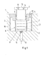
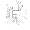
- FIG. 1 a section of a Biegeeinstellwalze 1 is shown.
- a pressure chamber 2 is formed in a fixed yoke 3.
- a support element 4 is guided.
- an insert 5 is provided within the pressure chamber 2, which has a vibration absorber 6 and the support member 4 radially movable.
- the vibration absorber 6 has a cylindrically formed microperforated resonator surface 7, which has a plurality of openings 8.
- annular seal 9 is arranged, which serves to seal the pressure chamber 2.
- the support member 4 has on a contact surface 10, two pressure pockets 11, 12, which serve to form a print film, not shown, which is formed between the contact surface 10 and an inner side of a roll jacket, not shown.
- the support member 4 thus serves to load the roll shell radially outward, this load from the pressure of a pressure medium in the pressure chamber 2 is dependent.
- the pressure medium is introduced via a pressure medium line 13 into the pressure chamber 2, wherein between the pressure medium line 13 and the pressure chamber 2, a throttle point 14 is arranged.
- the throttle point 14 may be formed so that its position within the pressure medium line 13 is variable and / or a size and / or number of throttle openings is variable. In this case, a first damping of pressure pulsations of the pressure medium, which are caused by vibrations of the roll shell and transmitted from the support element 4 to the pressure medium via the throttle point 14 takes place.
- a cylindrical wall 15 is provided, which belongs to the insert 5 in this embodiment. But it is also possible to realize the wall 15 through a wall in the yoke 3.
- a gas supply line 16 is further provided, through which a gas, such as air, can be introduced into a space 17 which is formed between the resonator surface 7 and the wall 15.
- Vibrations of the roll mantle are transmitted to the pressure medium by the support element 4 in the form of pressure pulsations.
- the pressure medium is reciprocated on the one hand via the throttle 14, whereby a first vibration damping takes place.
- the pressure medium is moved through the openings 8 in the microperforated resonator surface 7.
- the pressure pulsations are transmitted into the space 17, in which also pressure medium is present is.
- a vibration-damping material and, for example, a gas volume can be arranged in the space 17.
- the pressure medium arranged in the space 17 acts like a spring, whereby damping takes place through the flow resistance of the openings 8.
- An additional gas volume can influence the spring constant.
- Such a vibration absorber is used to dampen pressure pulsations with a frequency of 100 to 1500 Hz, which occur mainly in the case of stresses of the roll shell and subsequent transmission of the pressure pulsations in the pressure supply system.
- the vibration absorber or the resonator surface 7 is rigid, so that it can be relatively easily fixed in the roller.
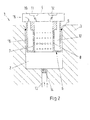
- Fig. 2 an embodiment of the vibration absorber 6 is shown, in which the resonator 7 is connected to the support member 4.
- An insert can be dispensed with in this embodiment, so that the support element 4 is guided directly in the yoke 2.
- the wall 15 is also fixed to the support member 4, so that the space 17 is moved in a movement of the support member 4.
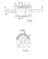
- Fig. 3 the use of the vibration absorber 6 is shown in a floating roller.
- the same parts are provided with the same reference numerals.
- the microperforated resonator surface 7 is arranged in a pressure chamber 2, which is supplied via a pressure medium line 13 with pressure medium. Between a roll shell 18 and the yoke 3 forms a pressurized oil pad. Between the pressure chamber 2 and a return 20, a differential pressure regulator 19 is arranged, which adjusts a pressure difference between the pressure chamber 2 and the return 20.
- the pressure medium is pressed through the openings 8 in the resonator 7 in a room in which also pressure medium is present, which acts as a spring.
- Fig. 4 is a sectional view of the Fig. 3 shown.
- the resonator surface 7 additionally has microperforated transverse webs 21, which lead to the formation of additional spaces. This allows a vibration damping over a wider range can be adjusted.
- a gas volume such as an air bubble, can be introduced into a space bounded by the resonator surface 7, whereby the spring stiffness is influenced.
- the damping behavior can also be influenced.
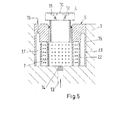
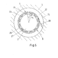
- FIG. 5 an embodiment of the vibration absorber 6 is shown, which except for the formation of a second resonator 22 according to the training Fig. 1 equivalent.
- the second resonator surface 22 is also microperforated and has openings 23 in a different size than the first resonator 7.
- the first resonator 7 and the second resonator 22 are rotationally symmetrical in the form of circular cylinders, wherein the first resonator 7 radially within the second Resonator surface 22 is arranged. Radially outside the second resonator surface 22 is the space 17, which is thus formed between the wall 15 and the second resonator surface 22.
- Fig. 6 a particular embodiment of the vibration absorber 6 is shown, wherein the micro-perforated resonator 7 is formed by two micro-perforated elements 24, 25 which bear radially against each other.
- the elements 24, 25 are tubular and each have openings 26, 27.
- an actuator 28 With the aid of an actuator 28, a rotational angle position between the elements 24, 25 can be adjusted.
- a rotational angle position between the elements 24, 25 can be adjusted.
- This is a relatively easy way to influence the size of the openings 8 in the resonator surface.
- the resonator surface 7 is formed by a tubular, rigid material.
- the resonator 7 can be used without problems at other locations of the pressure medium system, for example in a pressure medium line.
- the size of the openings is dependent on the frequency of the vibrations to be damped and the viscosity of the pressure medium.
- a diameter of the openings should be between 0.1 and 3 mm.
- the openings do not necessarily have to be of circular design, but may, for example, also be wave-shaped, square or slot-shaped. In this case, half the transverse dimension should be in the order of magnitude of the laminar boundary layer thickness of the pressure medium.
- a ratio of the openings or the microperforated area to the total area should be between 1% and 30%. The stability of the resonator surface is thus retained.
- the wall is always smooth.
- the wall may also have a structure, for example, be corrugated or wavy. In a waffle-shaped design of the wall, it is also conceivable to perforate these again. This results Another vibration damping. This is also achieved by the arrangement of a vibration damping material in the space between the resonator surface and the wall, which is also not shown in the figures.
- a vibration absorber is obtained, which is relatively easy to integrate into the pressure chamber or the pressure medium line, ie in the printing system of a bending compensating roll, which in particular vibration and fluidic properties are improved.
- the vibration absorber can be designed as an insert. This results in a relatively easy to retrofit and inexpensive solution.
Landscapes
- Physics & Mathematics (AREA)
- Fluid Mechanics (AREA)
- Rolls And Other Rotary Bodies (AREA)
- Vibration Prevention Devices (AREA)
Abstract
Description
- Die Erfindung betrifft eine Biegeausgleichswalze, insbesondere für eine Papier- oder Kartonmaschine mit einem umlaufenden Walzenmantel und einem feststehenden Joch, das den Walzenmantel axial durchsetzt, wobei der Walzenmantel durch den Druck eines Druckmittels in mindestens einer Druckkammer eines Drucksystems radial nach außen belastbar ist.
- Derartige Walzen werden als schwimmende Walzen oder als Walzen mit einer Reihe axial nebeneinander angeordneter Stützquellen zur Bildung eines Nips mit einer Gegenwalze eingesetzt. In dem Nip erfolgt eine Behandlung einer faserförmigen Materialbahn, in der Regel einer Papier- oder Kartonbahn. Die Materialbahn wird dabei im Nip mit erhöhtem Druck und gegebenenfalls erhöhter Temperatur beaufschlagt.
- Im Betrieb werden die Walze und insbesondere der Walzenmantel mit Erregerkräften beaufschlagt, die ein Schwingen des Walzenmantels bewirken. Erregerkräfte entstehen beispielsweise durch Inhomogenitäten, an Isotropien oder Geometriefehlern, aber auch durch Papierdickenschwankungen. Die resultierende Schwingung ist dabei in der Regel so klein, dass sie nicht unmittelbar stört. Allerdings prägen sich diese Schwingungsbewegungen nach einem längeren Zeitraum in den Walzenmantel ein, was zu einer Schwingungsverstärkung führt. Dies macht sich zum einen als akustische Schwingungen bemerkbar, also in einem erhöhten Schallpegel, kann aber auch zu periodischen Dickenschwankungen der Materialbahn führen, der so genannten Barring-Erscheinung.
- Zur Schwingungsdämpfung ist es nun beispielsweise aus
DE 10 2007 051 395 A1 bekannt, einen Schwingungsabsorber im Druckraum anzuordnen. Der Schwingungsabsorber weist eine Membran auf, die den Druckraum in zwei Kammern aufteilt. Ein durch die Membran abgetrennter Raum ist dabei mit einem kompressiblen Medium, wie beispielsweise Gas oder Luft, gefüllt. Dabei kann das kompressible Medium über eine Anschlussleitung in diesen Raum eingebracht werden. Auf der anderen Seite liegt das Druckmittel an der Membran an. Die mit Druckmittel gefüllte Druckkammer, die einem Stützelement zugeordnet ist, ist über eine Drosselstelle mit einer Anschlussleitung verbunden. Bei dieser Lösung erfolgt zum einen eine Schwingungsdämpfung über die Hin- und Herbewegung des Druckmittels über die Drosselstelle und zum anderen durch die Verformung der elastischen Membran unter Komprimierung des kompressiblen Mediums. - Eine derartige Lösung arbeitet relativ zufrieden stellend. Allerdings ist durch die erforderliche Elastizität der Membran die Haltbarkeit begrenzt. Auch stellt eine fluiddichte Befestigung der Membran innerhalb der Druckkammer eine Schwierigkeit dar.
- Der Erfindung liegt nun die Aufgabe zugrunde, Nachteile der aus dem Stand der Technik bekannten Lösungen zu vermeiden.
- Diese Aufgabe wird bei einer Biegeausgleichswalze der eingangs genannten Art dadurch gelöst, dass das Drucksystem mindestens einen Schwingungsabsorber mit mindestens einer mikroperforierten Resonatorfläche aufweist.
- Das Druckmittel kann dann durch die Öffnungen in der Resonatorfläche hindurch strömen, wobei das Druckmittel dabei von der Druckkammer in einen Raum strömt, der zumindest teilweise mit Druckmittel gefüllt ist. Dieses Druckmittel dient dabei als Feder und weist gleichzeitig eine gewisse Masse auf, wobei durch innere Reibung und die Reibung durch Durchströmung der mikroperforierten Resonatorfläche Energie abgebaut wird. Es wird so eine Art "Helmholtz-Resonator" erhalten. Der Schwingungsabsorber kann dabei in der Druckkammer angeordnet sein oder unmittelbar im Anschlussbereich einer Druckleitung. Dabei kann die Resonatorfläche starr und unelastisch ausgebildet sein, so dass also keine Schwierigkeiten hinsichtlich einer Befestigung des Schwingungsabsorbers im Drucksystem auftreten. Eine Materialermüdung der Resonatorfläche ist ebenfalls nicht zu befürchten. Dabei sind Schwingungen im Bereich von 100 bis 1500 Hz zu dämpfen, also in einem Bereich, in dem Barring auftritt. Eine Beanspruchung des Walzenmantels und eine Übertragung der Schwingungen in das Drucksystem wird damit vermindert.
- Bevorzugterweise sind 1 bis 30 % der Resonatorfläche durch Öffnungen gebildet. Die Resonatorfläche weist also relativ viele Öffnungen auf, durch die beim Auftreten von Druckpulsationen aufgrund von Schwingungen das Druckmittel hindurchfließen kann. Dadurch kann eine relativ große Menge an Druckmittel zur Schwingungsdämpfung ausgenutzt werden. Die Öffnungen können dabei unterschiedliche Größen aufweisen, so dass sie auf unterschiedliche Schwingungsfrequenzen abgestimmt sind.
- Dabei ist besonders bevorzugt, dass eine halbe Querabmessung der Öffnungen in der Größenordnung einer laminaren Grenzschichtdicke des Druckmittels liegt. Druckmittel ist in der Regel ein Hydrauliköl. Indem nun eine halbe Querabmessung der Öffnungen in der Größenordnung einer laminaren Grenzschicht des Druckmittels liegt, wird eine ausreichende Drosselwirkung und damit Dämpfungswirkung beim Durchströmen der Öffnungen sichergestellt. Eine Länge der Öffnungen kann dann größer ausgebildet sein.
- Vorzugsweise beträgt eine Länge der Öffnungen 0,5 bis 6 mm, insbesondere 1 bis 5 mm. Öffnungen in dieser Größe lassen sich relativ einfach mit herkömmlichen Mitteln herstellen. So können sie beispielsweise erodiert, gestanzt oder durch Laserstrahlschweißen bzw. -schneiden erzeugt werden.
- Vorteilhafterweise beträgt bei kreisförmigen Öffnungen ein Durchmesser zwischen 0,1 und 3 mm. Die Herstellung derartiger Öffnungen stellt technologisch keine Schwierigkeit dar. Gleichzeitig lässt sich eine ausreichend große Durchflussmenge erreichen.
- Vorzugsweise ist zwischen der Resonatorfläche und einer insbesondere dazu parallelen Wand ein Raum ausgebildet, wobei die Wand in einem Abstand von 1 bis 30 mm von der Resonatorfläche angeordnet ist. Dieser Raum ist zumindest teilweise mit dem Druckmittel gefüllt, wenn sich der Schwingungsabsorber in Benutzung befindet, um das Auftreten von Kavität der Resonatorfläche zu verhindern. Das Druckmittel, das in diesem Raum angeordnet ist, wird dabei als Feder genutzt. Ein Abstand der Wand von der Resonatorfläche in der Größenordnung von 1 bis 30 mm stellt dabei einen guten Kompromiss dar, zwischen einem benötigten Bauraum und der Menge an Druckmittel, das darin aufgenommen werden kann, wobei diese Menge Einfluss auf die Federkonstante hat.
- Dabei ist besonders bevorzugt, dass die Wand strukturiert ist. Die Wand kann dabei beispielsweise geriffelt oder gewellt sein oder auch eine Wabenstruktur aufweisen. Dies verbessert die Schwingungsabsorption. Dabei ist aufgrund der Struktur ein Abstand der Wandfläche von der Resonatorfläche nicht immer konstant, so dass ein Wirkungsbereich des Schwingungsabsorbers verbreitert wird.
- Dabei ist besonders bevorzugt, dass in dem Raum ein schwingungsdämpfendes Material angeordnet ist. Ein derartiges Material ist beispielsweise ein Gasvolumen, das ohne Einsatz einer Membran als reine Luftblase in dem Raum angeordnet werden kann. Ein derartiges Gasvolumen muss lediglich alle paar Tage erneuert werden, was ohne Probleme während des Betriebs der Walze möglich ist. Als schwingungsdämpfendes Material kann aber auch ein poröses, faserförmiges oder auch kugelförmiges Material verwendet werden. Durch ein schwingungsdämpfendes Material, das in dem Raum zwischen der Wand und der Resonatorfläche angeordnet ist, lässt sich die Schwingungsdämpfung erhöhen. Als Materialien eigen sich beispielsweise Stahlfasern, Mineralfasern, Glasfasern, Aramidfasern, Hohlfasern, Schäume, syntaktische Schäume, Kunststofffasern, Kohlefasern, Metallschäume, Sinterkeramikwerkstoffe, kugelförmige Schüttungen und Ähnliches.
- In einer bevorzugten Ausgestaltung ist die Resonatorfläche rotationssymmetrisch ausgebildet. Die Resonatorfläche bildet also die Umfangswand eines Zylinders mit offenen Stirnseiten. Dabei kann die Resonatorfläche direkt in der Druckkammer angeordnet sein, wobei die Wand durch eine äußere Begrenzungswand der Druckkammer gebildet ist. Dabei ist es insbesondere vorteilhaft, wenn die Resonatorfläche symmetrisch im Druckraum angeordnet ist, also rotationssymmetrisch um eine zentrale Achse der Druckkammer. Bei einer rotationssymmetrischen Ausbildung der Resonatorfläche lässt sich diese aber auch relativ einfach in die Druckmittelleitung integrieren, so dass durch den Einsatz des Schwingungsabsorbers keine Änderung an der Druckkammer selbst erforderlich ist.
- Bevorzugterweise ist parallel zur Resonatorfläche mindestens eine zweite Resonatorfläche ausgebildet, die insbesondere Öffnungen in einer anderen Größe aufweist. Diese zweite Resonatorfläche kann räumlich parallel bzw. hinter der ersten Resonatorfläche angeordnet werden, so dass der Schwingungsabsorber in Summe breitbandiger ausgeführt werden kann. Dies wird insbesondere dadurch erreicht, dass in der zweiten Resonatorfläche Löcher einer anderen Größe ausgebildet sind als in der ersten Resonatorfläche.
- Vorzugsweise ist eine Größe der Öffnungen veränderbar. Die Öffnungen können zum Erreichen einer breitbandigen Schwingungsdämpfung zwar unterschiedlich groß sein, durch die Möglichkeit, die Größe der Öffnungen zu verändern, ist es jedoch möglich, den Schwingungsabsorber individuell auf die auftretenden Schwingungen einzustellen, so dass ein optimales Dämpfungsverhalten erreicht wird. Dabei ist es denkbar, einzelne Öffnungen verschließbar zu gestalten, so dass also auch die Öffnungsanzahl verändert werden kann. Dadurch kann das Dämpfungsverhalten in weiten Bereichen adaptiv eingestellt werden. Dafür können verschiedene aktuatorische Hilfsmittel vorgesehen sein, beispielsweise hydraulische, pneumatische, elektromotorische oder piezokeramische Elemente.
- Vorzugsweise weist die Resonatorfläche zwei gegeneinander verschiebbare, mikroperforierte Elemente auf. Durch eine Relativbewegung dieser beiden, aneinander liegenden Elemente lässt sich die Größe und Anzahl der Öffnungen in der Resonatorfläche über einen weiten Bereich einstellen. Bei einer zylindrischen bzw. rotationssymmetrischen Ausbildung der Resonatorfläche können die beiden Elemente dabei gegeneinander verdrehbar ausgeführt sein. Dafür kann ein entsprechend ausgebildeter Aktuator vorgesehen sein.
- Vorteilhafterweise ist ein Abstand zwischen der Resonatorfläche und der Wand einstellbar. Dadurch lässt sich ein Absorptionsgrad des Schwingungsabsorbers einstellen. Dabei ist es ausreichend, entweder die Resonatorfläche oder die Wand bewegbar auszuführen, wobei die Bewegung beispielsweise durch ein hydraulisches, pneumatisches, elektromotorisches oder piezokeramisches Element erfolgt.
- Vorteilhafterweise ist dabei eine Sensoreinrichtung zur Schwingungserfassung vorgesehen, wobei eine Größe und/oder eine Anzahl der Öffnungen der Resonatorfläche und/oder ein Abstand zwischen der Resonatorfläche und der Wand in Abhängigkeit der erfassten Schwingungen eingestellt wird. Eine Dämpfung der Schwingungen erfolgt also über einen Regelkreis. Dabei lässt sich eine aktive Schwingungsdämpfung erreichen.
- Vorzugsweise ist die Druckkammer über eine Drosselstelle mit einer Druckleitung verbunden, wobei insbesondere eine Größe und/oder Anzahl an Durchflussöffnungen der Drosselstelle und/oder eine Position der Drosselstelle veränderbar ist. In der Drosselstelle wird zusätzlich Schwingungsenergie abgebaut. Dabei kann durch die Einstellmöglichkeiten eine relativ genaue Anpassung an die gerade zu dämpfende Schwingungsfrequenz erfolgen. Das Auftreten von Barring kann so effektiv verhindert werden.
- Vorzugsweise ist die Druckkammer im Joch angeordnet, wobei in der Druckkammer ein Stützelement geführt ist, das durch einen Druck in der Druckkammer mit einer Anlegeseite gegen den Walzenmantel drückbar ist. Das Stützelement ist dabei radial in der Druckkammer geführt und bildet dabei eine Seite der Druckkammer. Zwischen einer Wand der Druckkammer und dem Stützelement kann dabei eine Radialdichtung vorgesehen sein. Zwischen dem Stützelement und dem Walzenmantel kann dabei ein Ölfilm ausgebildet sein, der beispielsweise eine Dicke von 20 bis 50 µm aufweist und damit eine sehr steife Ankupplung ermöglicht. Schwingungen des Walzenmantels werden daher direkt über das Stützelement in die Druckkammer und damit auf das Druckmittel übertragen.
- Die Erfindung wird im Folgenden anhand bevorzugter Ausführungsbeispiele in Verbindung mit der Zeichnung näher beschrieben. Hierin zeigen:
- Fig. 1
- eine Druckkammer einer Biegeeinstellwalze mit einem Schwingungsabsorber einer ersten Ausführungsform,
- Fig. 2
- eine Druckkammer mit einem Schwingungsabsorber einer zweiten Ausführungsform,
- Fig. 3
- eine schwimmende Walze mit einem Schwingungsabsorber,
- Fig. 4
- einen Querschnitt der schwimmenden Walze nach
Fig. 3 , - Fig. 5
- eine Ausbildung des Schwingungsabsorbers mit zwei Resonatorflächen und
- Fig. 6
- eine Ausbildung des Schwingungsabsorbers mit zwei gegeneinander verschiebbaren Elementen.
- In
Fig. 1 ist ein Ausschnitt einer Biegeeinstellwalze 1 dargestellt. Eine Druckkammer 2 ist in einem feststehenden Joch 3 ausgebildet. In der Druckkammer 2 ist ein Stützelement 4 geführt. Dabei ist innerhalb der Druckkammer 2 ein Einsatz 5 vorgesehen, der einen Schwingungsabsorber 6 aufweist und das Stützelement 4 radial beweglich führt. Der Schwingungsabsorber 6 weist eine zylindrisch ausgebildete mikroperforierte Resonatorfläche 7 auf, die eine Vielzahl an Öffnungen 8 aufweist. Zwischen dem Einsatz 5 und dem Stützelement 4 ist eine Ringdichtung 9 angeordnet, die zur Abdichtung der Druckkammer 2 dient. - Das Stützelement 4 weist an einer Anlagefläche 10 zwei Drucktaschen 11, 12 auf, die zur Ausbildung eines nicht dargestellten Druckfilms dienen, der zwischen der Anlagefläche 10 und einer Innenseite eines nicht dargestellten Walzenmantels ausgebildet ist. Das Stützelement 4 dient also dazu, den Walzenmantel radial nach außen zu belasten, wobei diese Belastung vom Druck eines Druckmittels in der Druckkammer 2 abhängig ist. Das Druckmittel wird dabei über eine Druckmittelleitung 13 in die Druckkammer 2 eingebracht, wobei zwischen der Druckmittelleitung 13 und der Druckkammer 2 eine Drosselstelle 14 angeordnet ist. Die Drosselstelle 14 kann dabei so ausgebildet sein, dass ihre Position innerhalb der Druckmittelleitung 13 veränderbar ist und/oder eine Größe und/oder Anzahl an Drosselöffnungen veränderbar ist. Über die Drosselstelle 14 erfolgt dabei eine erste Dämpfung von Druckpulsationen des Druckmittels, die durch Schwingungen des Walzenmantels hervorgerufen werden und vom Stützelement 4 auf das Druckmittel übertragen werden.
- Parallel zur Resonatorfläche 7 ist eine zylindrische Wand 15 vorgesehen, die bei diesem Ausführungsbeispiel zum Einsatz 5 gehört. Es ist aber auch möglich, die Wand 15 durch eine Wandung im Joch 3 zu realisieren.
- Im Einsatz 5 ist ferner eine Gaszuleitung 16 vorgesehen, durch die ein Gas, wie beispielsweise Luft, in einen Raum 17 eingebracht werden kann, der zwischen der Resonatorfläche 7 und der Wand 15 ausgebildet ist.
- Schwingungen des Walzenmantels werden durch das Stützelement 4 in Form von Druckpulsationen auf das Druckmittel übertragen. Das Druckmittel wird dabei zum einen über die Drossel 14 hin- und herbewegt, wodurch eine erste Schwingungsdämpfung erfolgt. Ferner wird das Druckmittel durch die Öffnungen 8 in der mikroperforierten Resonatorfläche 7 bewegt. Dadurch werden die Druckpulsationen in den Raum 17 übertragen, in dem ebenfalls Druckmittel vorhanden ist. Ferner kann in dem Raum 17 ein schwingungsdämpfendes Material und beispielsweise ein Gasvolumen angeordnet sein. Das im Raum 17 angeordnete Druckmittel wirkt dabei wie eine Feder, wobei durch den Strömungswiderstand der Öffnungen 8 eine Dämpfung erfolgt. Durch ein zusätzliches Gasvolumen kann dabei die Federkonstante beeinflusst werden. Durch schwingungsdämpfendes Material innerhalb des Raums 17 erfolgt eine stärkere Schwingungsdämpfung. Dadurch erfolgt eine effektivere Schwingungsdämpfung mit dem Schwingungsabsorber 6.
- Ein derartiger Schwingungsabsorber dient zum Dämpfen von Druckpulsationen mit einer Frequenz von 100 bis 1500 Hz, die vor allem bei Beanspruchungen des Walzenmantels und nachfolgender Übertragung der Druckpulsationen in das Druckzufuhrsystem auftreten. Der Schwingungsabsorber bzw. die Resonatorfläche 7 ist dabei starr ausgeführt, so dass dieser relativ einfach in der Walze befestigt werden kann.
- In
Fig. 2 ist eine Ausgestaltung des Schwingungsabsorbers 6 gezeigt, bei der die Resonatorfläche 7 mit dem Stützelement 4 verbunden ist. Auf einen Einsatz kann bei dieser Ausgestaltung verzichtet werden, so dass das Stützelement 4 direkt im Joch 2 geführt ist. Die Wand 15 ist dabei ebenfalls am Stützelement 4 festgelegt, so dass auch der Raum 17 bei einer Bewegung des Stützelements 4 mitbewegt wird. - Im Übrigen entspricht die Ausgestaltung der
Fig. 2 der Ausgestaltung nachFig. 1 . - In
Fig. 3 ist der Einsatz des Schwingungsabsorbers 6 in einer schwimmenden Walze dargestellt. Gleiche Teile sind dabei mit gleichen Bezugszeichen versehen. Die mikroperforierte Resonatorfläche 7 ist dabei in einer Druckkammer 2 angeordnet, die über eine Druckmittelleitung 13 mit Druckmittel versorgt wird. Zwischen einem Walzenmantel 18 und dem Joch 3 bildet sich dabei ein unter Druck stehendes Ölpolster aus. Zwischen der Druckkammer 2 und einem Rücklauf 20 ist ein Differenzdruckregulator 19 angeordnet, der einen Druckunterschied zwischen der Druckkammer 2 und dem Rücklauf 20 einstellt. - Wie auch bei den Ausführungsformen nach den
Fig. 1 und2 erfolgt hier eine Schwingungsdämpfung durch die Übertragung von Druckpulsationen durch die Öffnungen 8 in der mikroperforierten Resonatorfläche 7. Das Druckmittel wird dabei durch die Öffnungen 8 in der Resonatorfläche 7 in einen Raum gedrückt, in dem ebenfalls Druckmittel vorhanden ist, das dabei als Feder wirkt. - In
Fig. 4 ist eine Schnittdarstellung derFig. 3 gezeigt. Die Resonatorfläche 7 weist zusätzlich mikroperforierte Querstege 21 auf, die zur Ausbildung zusätzlicher Räume führen. Dadurch kann eine Schwingungsdämpfung über einen breiteren Bereich eingestellt werden. Über die Gaszuleitung 16 kann ein Gasvolumen, wie beispielsweise eine Luftblase, in einen von der Resonatorfläche 7 begrenzten Raum eingebracht werden, wodurch eine Beeinflussung der Federsteifigkeit erfolgt. Damit kann also ebenfalls das Dämpfungsverhalten beeinflusst werden. - In
Fig. 5 ist eine Ausbildung des Schwingungsabsorbers 6 dargestellt, die bis auf die Ausbildung einer zweiten Resonatorfläche 22 der Ausbildung nachFig. 1 entspricht. Die zweite Resonatorfläche 22 ist dabei ebenfalls mikroperforiert und weist Öffnungen 23 in einer anderen Größe auf als die erste Resonatorfläche 7. Die erste Resonatorfläche 7 und die zweite Resonatorfläche 22 sind dabei rotationssymmetrisch in Form von Kreiszylindern ausgebildet, wobei die erste Resonatorfläche 7 radial innerhalb der zweiten Resonatorfläche 22 angeordnet ist. Radial außerhalb der zweiten Resonatorfläche 22 befindet sich der Raum 17, der also zwischen der Wand 15 und der zweiten Resonatorfläche 22 ausgebildet ist. - Durch das Vorsehen zweier Resonatorflächen kann ein relativ breitbandiges Dämpfungsverhalten erzielt werden.
- Gegebenenfalls ist es auch möglich, noch weitere Resonatorflächen vorzusehen.
- In
Fig. 6 ist eine besondere Ausgestaltung des Schwingungsabsorbers 6 dargestellt, wobei die mikroperforierte Resonatorfläche 7 durch zwei mikroperforierte Elemente 24, 25 gebildet ist, die radial aneinander anliegen. Die Elemente 24, 25 sind dabei rohrförmig ausgebildet und weisen jeweils Öffnungen 26, 27 auf. Mit Hilfe eines Aktuators 28 kann eine Drehwinkellage zwischen den Elementen 24, 25 eingestellt werden. Je nach eingestelltem Winkel ergibt sich dabei ein unterschiedlicher Überdeckungsgrad der Öffnungen 26, 27, wodurch die Größe von Öffnungen in der Resonatorfläche 7 eingestellt werden kann. Dies stellt eine relativ einfache Möglichkeit dar, die Größe der Öffnungen 8 in der Resonatorfläche zu beeinflussen. - In den Ausführungsbeispielen gemäß der
Fig. 1 ,2 ,5 und6 ist die Resonatorfläche 7 durch ein rohrförmiges, steifes Material gebildet. Bei einer derartigen Ausgestaltung kann die Resonatorfläche 7 auch ohne Probleme an anderen Stellen des Druckmittelsystems, beispielsweise in einer Druckmittelleitung, eingesetzt werden. Die Größe der Öffnungen ist dabei von der Frequenz der zu dämpfenden Schwingungen und der Viskosität des Druckmittels abhängig. Bei hydraulischen Druckmitteln sollte ein Durchmesser der Öffnungen zwischen 0,1 und 3 mm liegen. Die Öffnungen müssen aber nicht unbedingt kreisförmig ausgestaltet sein, sondern können beispielsweise auch wellenförmig, quadratisch oder als Schlitz ausgebildet sein. Dabei sollte eine halbe Querabmessung in der Größenordnung der laminaren Grenzschichtdicke des Druckmittels liegen. - Ein Verhältnis der Öffnungen bzw. der mikroperforierten Fläche zur Gesamtfläche sollte dabei zwischen 1 % und 30 % liegen. Die Stabilität der Resonatorfläche bleibt damit erhalten.
- Bei den Ausführungsbeispielen ist die Wand immer glatt ausgebildet. Die Wand kann aber auch eine Struktur aufweisen, beispielsweise geriffelt oder gewellt sein. Bei einer waffelförmigen Ausgestaltung der Wand ist es auch denkbar, diese nochmals zu perforieren. Dadurch ergibt sich eine weitere Schwingungsdämpfung. Diese wird auch durch die Anordnung eines schwingungsdämpfenden Materials in dem Raum zwischen der Resonatorfläche und der Wand erreicht, was ebenfalls in den Figuren nicht dargestellt ist.
- Durch die erfindungsgemäße Ausgestaltung wird ein Schwingungsabsorber erhalten, der relativ einfach in den Druckraum oder die Druckmittelleitung, also in das Drucksystem einer Biegeausgleichswalze zu integrieren ist, wodurch insbesondere schwingungs- und strömungstechnische Eigenschaften verbessert werden. Dabei kann der Schwingungsabsorber als Einsatz ausgebildet sein. Es ergibt sich so eine relativ einfach nachrüstbare und preiswerte Lösung.
Claims (14)
- Biegeausgleichswalze, insbesondere für eine Papier-oder Kartonmaschine, mit einem umlaufenden Walzenmantel und einem feststehenden Joch, das den Walzenmantel axial durchsetzt, wobei der Walzenmantel durch den Druck eines Druckmittels in mindestens einer Druckkammer eines Drucksystems radial nach außen belastbar ist, dadurch gekennzeichnet, dass das Drucksystem mindestens einen Schwingungsabsorber (6) mit mindestens einer mikroperforierten Resonatorfläche (7, 22) aufweist.
- Biegeausgleichswalze nach Anspruch 1, dadurch gekennzeichnet, dass 1 bis 30 % der Resonatorfläche durch Öffnungen (8, 23) gebildet sind.
- Biegeausgleichswalze nach Anspruch 1 oder 2, dadurch gekennzeichnet, dass eine halbe Querabmessung der Öffnungen (8, 23) in der Größenordnung einer laminaren Grenzschichtdicke des Druckmittels liegt.
- Biegeausgleichswalze nach einem der Ansprüche 1 bis 3, dadurch gekennzeichnet, dass eine Länge der Öffnungen (8, 23) 0,5 bis 6 mm, insbesondere 1 bis 5 mm beträgt.
- Biegeausgleichswalze nach einem der Ansprüche 1 bis 3, dadurch gekennzeichnet, dass bei kreisförmigen Öffnungen (8, 23) ein Durchmesser zwischen 0,1 und 3 mm beträgt.
- Biegeausgleichswalze nach einem der Ansprüche 1 bis 5, dadurch gekennzeichnet, dass ein Raum (17) zwischen der Resonatorfläche (7, 22) und einer insbesondere dazu parallelen Wand (15) ausgebildet ist, wobei die Wand (15) in einem Abstand von 1 bis 30 mm von der Resonatorfläche (7, 22) angeordnet ist.
- Biegeausgleichswalze nach Anspruch 6, dadurch gekennzeichnet, dass die Wand (15) strukturiert ist.
- Biegeausgleichswalze nach einem der Ansprüche 1 bis 7, dadurch gekennzeichnet, dass in dem Raum (17) ein schwingungsdämpfendes Material und/oder ein Gasvolumen angeordnet ist.
- Biegeausgleichswalze nach einem der Ansprüche 1 bis 8, dadurch gekennzeichnet, dass die Resonatorfläche (7, 22) rotationssymmetrisch ausgebildet ist.
- Biegeausgleichswalze nach einem der Ansprüche 1 bis 9,dadurch gekennzeichnet, dass parallel zur ersten Resonatorfläche (7) eine zweite Resonatorfläche (22) ausgebildet ist, die insbesondere Öffnungen (23) in einer anderen Größe als die erste Resonatorfläche (7) aufweist.
- Biegeausgleichswalze nach einem der Ansprüche 1 bis 10, dadurch gekennzeichnet, dass eine Größe der Öffnungen (8, 23) veränderbar ist.
- Biegeausgleichswalze nach einem der Ansprüche 1 bis 11, dadurch gekennzeichnet, dass die Resonatorfläche (7) zwei gegeneinander verschiebbare, mikroperforierte Elemente (24, 25) aufweist.
- Biegeausgleichswalze nach einem der Ansprüche 6 bis 12, dadurch gekennzeichnet, dass ein Abstand zwischen der Resonatorfläche (7, 22) und der Wand (15) veränderbar ist.
- Biegeausgleichswalze nach einem der Ansprüche 1 bis 13, dadurch gekennzeichnet, dass eine Sensoreinrichtung zur Schwingungserfassung vorgesehen ist, wobei eine Größe und/oder eine Anzahl der Öffnungen (8, 23) der Resonatorfläche (7, 22) und/oder ein Abstand zwischen der Resonatorfläche (7, 22) und der Wand (15) in Abhängigkeit der erfassten Schwingungen eingestellt wird.
Applications Claiming Priority (1)
| Application Number | Priority Date | Filing Date | Title |
|---|---|---|---|
| DE201110005922 DE102011005922A1 (de) | 2011-03-23 | 2011-03-23 | Biegeausgleichswalze mit Schwingungsabsorber |
Publications (2)
| Publication Number | Publication Date |
|---|---|
| EP2503056A1 true EP2503056A1 (de) | 2012-09-26 |
| EP2503056B1 EP2503056B1 (de) | 2014-05-14 |
Family
ID=45936746
Family Applications (1)
| Application Number | Title | Priority Date | Filing Date |
|---|---|---|---|
| EP20120159151 Not-in-force EP2503056B1 (de) | 2011-03-23 | 2012-03-13 | Biegeausgleichswalze mit Schwingungsabsorber |
Country Status (2)
| Country | Link |
|---|---|
| EP (1) | EP2503056B1 (de) |
| DE (1) | DE102011005922A1 (de) |
Citations (5)
| Publication number | Priority date | Publication date | Assignee | Title |
|---|---|---|---|---|
| DE102005049524A1 (de) * | 2004-11-11 | 2006-05-24 | Metso Paper, Inc. | Anordnung zur Verringerung der Schwingungen einer Durchbiegungseinstellwalze |
| EP1731669A1 (de) * | 2005-06-10 | 2006-12-13 | Voith Patent GmbH | Biegeausgleichswalze |
| EP1876364A2 (de) * | 2006-07-04 | 2008-01-09 | Voith Patent GmbH | Biegeausgleichswalze und Verfahren zum Betreiben einer Biegeausgleichswalze |
| DE102007051395A1 (de) | 2006-10-30 | 2008-05-08 | Metso Paper, Inc. | Durchbiegungseinstellwalze für eine Papier-, Karton oder Ausrüstungsmaschine |
| DE102009018051A1 (de) * | 2008-04-23 | 2009-11-05 | Metso Paper, Inc. | Biegungskompensierte Walze einer Faserbahn- oder Ausrüstungsmaschine, Verfahren zur Verwendung und Herstellung der biegungskompensierten Walze und Vorrichtung zur Dämpfung von Schwingungen in einem hydraulischen Druckmedium |
-
2011
- 2011-03-23 DE DE201110005922 patent/DE102011005922A1/de not_active Withdrawn
-
2012
- 2012-03-13 EP EP20120159151 patent/EP2503056B1/de not_active Not-in-force
Patent Citations (5)
| Publication number | Priority date | Publication date | Assignee | Title |
|---|---|---|---|---|
| DE102005049524A1 (de) * | 2004-11-11 | 2006-05-24 | Metso Paper, Inc. | Anordnung zur Verringerung der Schwingungen einer Durchbiegungseinstellwalze |
| EP1731669A1 (de) * | 2005-06-10 | 2006-12-13 | Voith Patent GmbH | Biegeausgleichswalze |
| EP1876364A2 (de) * | 2006-07-04 | 2008-01-09 | Voith Patent GmbH | Biegeausgleichswalze und Verfahren zum Betreiben einer Biegeausgleichswalze |
| DE102007051395A1 (de) | 2006-10-30 | 2008-05-08 | Metso Paper, Inc. | Durchbiegungseinstellwalze für eine Papier-, Karton oder Ausrüstungsmaschine |
| DE102009018051A1 (de) * | 2008-04-23 | 2009-11-05 | Metso Paper, Inc. | Biegungskompensierte Walze einer Faserbahn- oder Ausrüstungsmaschine, Verfahren zur Verwendung und Herstellung der biegungskompensierten Walze und Vorrichtung zur Dämpfung von Schwingungen in einem hydraulischen Druckmedium |
Also Published As
| Publication number | Publication date |
|---|---|
| EP2503056B1 (de) | 2014-05-14 |
| DE102011005922A1 (de) | 2012-09-27 |
Similar Documents
| Publication | Publication Date | Title |
|---|---|---|
| DE102004059406B4 (de) | Mit einem Fluid gefüllte Schwingungsdämpfungsvorrichtung | |
| EP2786040B1 (de) | Wellenanordnung sowie verfahren zum weiterleiten von um eine drehachse wirkenden drehmomenten | |
| EP1411254B1 (de) | Mittelwalze eines Kalanders mit einer Tilgeranordnung | |
| EP0268769B1 (de) | Walze für die Druckbehandlung von Warenbahnen | |
| EP3158217B1 (de) | Hydrolager sowie kraftfahrzeug mit einem derartigen hydrolager | |
| EP2052796B1 (de) | Verfahren und Vorrichtung zum Unterdrücken des Ratterns von Arbeitswalzen eines Walzgerüsts | |
| EP2503056B1 (de) | Biegeausgleichswalze mit Schwingungsabsorber | |
| DE102009055767A1 (de) | Druckzylinderanordnung für eine Rotationsdruckmaschine | |
| DE102005026907A1 (de) | Biegeausgleichwalze | |
| EP1692343B2 (de) | Schwingungsgedämpfte walze | |
| EP3221613B1 (de) | Hydrolager sowie kraftfahrzeug mit einem derartigen hydrolager | |
| EP2366911A1 (de) | Walze für eine Papier- oder Kartonmaschine und Verfahren zum Dämpfen von Schwingungen einer Walze | |
| WO2016078807A1 (de) | Hydrolager sowie kraftfahrzeug mit einem derartigen hydrolager | |
| EP2423383B1 (de) | Walze für eine Papier- oder Kartonmaschine | |
| EP1790600B1 (de) | Rollenwickeleinrichtung | |
| EP2426256B1 (de) | Biegeausgleichswalze für eine Papier- oder Kartonmaschine | |
| DE102014107493B3 (de) | Ultraschalllager | |
| EP2577078A1 (de) | Walze und verfahren zur vermeidung ihrer schwingungen | |
| EP2059692A1 (de) | Hydraulisch gedämpftes aggregatlager | |
| DE102006023831A1 (de) | Rollenwickeleinrichtung | |
| DE102010060699B3 (de) | Rotierendes Maschinenteil | |
| EP2423382A1 (de) | Vorrichtung und Verfahren zur Reduzierung von Schwingungen an einer Biegeeinstellwalze | |
| DE102011076482A1 (de) | Wickelverfahren und Rollenwickelvorrichtung |
Legal Events
| Date | Code | Title | Description |
|---|---|---|---|
| PUAI | Public reference made under article 153(3) epc to a published international application that has entered the european phase |
Free format text: ORIGINAL CODE: 0009012 |
|
| AK | Designated contracting states |
Kind code of ref document: A1 Designated state(s): AL AT BE BG CH CY CZ DE DK EE ES FI FR GB GR HR HU IE IS IT LI LT LU LV MC MK MT NL NO PL PT RO RS SE SI SK SM TR |
|
| AX | Request for extension of the european patent |
Extension state: BA ME |
|
| 17P | Request for examination filed |
Effective date: 20130326 |
|
| GRAP | Despatch of communication of intention to grant a patent |
Free format text: ORIGINAL CODE: EPIDOSNIGR1 |
|
| RIC1 | Information provided on ipc code assigned before grant |
Ipc: D21G 1/02 20060101AFI20131007BHEP |
|
| INTG | Intention to grant announced |
Effective date: 20131029 |
|
| GRAS | Grant fee paid |
Free format text: ORIGINAL CODE: EPIDOSNIGR3 |
|
| GRAA | (expected) grant |
Free format text: ORIGINAL CODE: 0009210 |
|
| AK | Designated contracting states |
Kind code of ref document: B1 Designated state(s): AL AT BE BG CH CY CZ DE DK EE ES FI FR GB GR HR HU IE IS IT LI LT LU LV MC MK MT NL NO PL PT RO RS SE SI SK SM TR |
|
| REG | Reference to a national code |
Ref country code: GB Ref legal event code: FG4D Free format text: NOT ENGLISH |
|
| REG | Reference to a national code |
Ref country code: AT Ref legal event code: REF Ref document number: 668410 Country of ref document: AT Kind code of ref document: T Effective date: 20140615 |
|
| REG | Reference to a national code |
Ref country code: IE Ref legal event code: FG4D Free format text: LANGUAGE OF EP DOCUMENT: GERMAN |
|
| REG | Reference to a national code |
Ref country code: DE Ref legal event code: R096 Ref document number: 502012000717 Country of ref document: DE Effective date: 20140626 |
|
| REG | Reference to a national code |
Ref country code: NL Ref legal event code: VDEP Effective date: 20140514 |
|
| REG | Reference to a national code |
Ref country code: LT Ref legal event code: MG4D |
|
| PG25 | Lapsed in a contracting state [announced via postgrant information from national office to epo] |
Ref country code: CY Free format text: LAPSE BECAUSE OF FAILURE TO SUBMIT A TRANSLATION OF THE DESCRIPTION OR TO PAY THE FEE WITHIN THE PRESCRIBED TIME-LIMIT Effective date: 20140514 Ref country code: NO Free format text: LAPSE BECAUSE OF FAILURE TO SUBMIT A TRANSLATION OF THE DESCRIPTION OR TO PAY THE FEE WITHIN THE PRESCRIBED TIME-LIMIT Effective date: 20140814 Ref country code: LT Free format text: LAPSE BECAUSE OF FAILURE TO SUBMIT A TRANSLATION OF THE DESCRIPTION OR TO PAY THE FEE WITHIN THE PRESCRIBED TIME-LIMIT Effective date: 20140514 Ref country code: GR Free format text: LAPSE BECAUSE OF FAILURE TO SUBMIT A TRANSLATION OF THE DESCRIPTION OR TO PAY THE FEE WITHIN THE PRESCRIBED TIME-LIMIT Effective date: 20140815 Ref country code: IS Free format text: LAPSE BECAUSE OF FAILURE TO SUBMIT A TRANSLATION OF THE DESCRIPTION OR TO PAY THE FEE WITHIN THE PRESCRIBED TIME-LIMIT Effective date: 20140914 |
|
| PG25 | Lapsed in a contracting state [announced via postgrant information from national office to epo] |
Ref country code: ES Free format text: LAPSE BECAUSE OF FAILURE TO SUBMIT A TRANSLATION OF THE DESCRIPTION OR TO PAY THE FEE WITHIN THE PRESCRIBED TIME-LIMIT Effective date: 20140514 Ref country code: SE Free format text: LAPSE BECAUSE OF FAILURE TO SUBMIT A TRANSLATION OF THE DESCRIPTION OR TO PAY THE FEE WITHIN THE PRESCRIBED TIME-LIMIT Effective date: 20140514 Ref country code: RS Free format text: LAPSE BECAUSE OF FAILURE TO SUBMIT A TRANSLATION OF THE DESCRIPTION OR TO PAY THE FEE WITHIN THE PRESCRIBED TIME-LIMIT Effective date: 20140514 Ref country code: HR Free format text: LAPSE BECAUSE OF FAILURE TO SUBMIT A TRANSLATION OF THE DESCRIPTION OR TO PAY THE FEE WITHIN THE PRESCRIBED TIME-LIMIT Effective date: 20140514 Ref country code: PL Free format text: LAPSE BECAUSE OF FAILURE TO SUBMIT A TRANSLATION OF THE DESCRIPTION OR TO PAY THE FEE WITHIN THE PRESCRIBED TIME-LIMIT Effective date: 20140514 Ref country code: LV Free format text: LAPSE BECAUSE OF FAILURE TO SUBMIT A TRANSLATION OF THE DESCRIPTION OR TO PAY THE FEE WITHIN THE PRESCRIBED TIME-LIMIT Effective date: 20140514 |
|
| PG25 | Lapsed in a contracting state [announced via postgrant information from national office to epo] |
Ref country code: PT Free format text: LAPSE BECAUSE OF FAILURE TO SUBMIT A TRANSLATION OF THE DESCRIPTION OR TO PAY THE FEE WITHIN THE PRESCRIBED TIME-LIMIT Effective date: 20140915 |
|
| PG25 | Lapsed in a contracting state [announced via postgrant information from national office to epo] |
Ref country code: CZ Free format text: LAPSE BECAUSE OF FAILURE TO SUBMIT A TRANSLATION OF THE DESCRIPTION OR TO PAY THE FEE WITHIN THE PRESCRIBED TIME-LIMIT Effective date: 20140514 Ref country code: SK Free format text: LAPSE BECAUSE OF FAILURE TO SUBMIT A TRANSLATION OF THE DESCRIPTION OR TO PAY THE FEE WITHIN THE PRESCRIBED TIME-LIMIT Effective date: 20140514 Ref country code: RO Free format text: LAPSE BECAUSE OF FAILURE TO SUBMIT A TRANSLATION OF THE DESCRIPTION OR TO PAY THE FEE WITHIN THE PRESCRIBED TIME-LIMIT Effective date: 20140514 Ref country code: EE Free format text: LAPSE BECAUSE OF FAILURE TO SUBMIT A TRANSLATION OF THE DESCRIPTION OR TO PAY THE FEE WITHIN THE PRESCRIBED TIME-LIMIT Effective date: 20140514 Ref country code: DK Free format text: LAPSE BECAUSE OF FAILURE TO SUBMIT A TRANSLATION OF THE DESCRIPTION OR TO PAY THE FEE WITHIN THE PRESCRIBED TIME-LIMIT Effective date: 20140514 |
|
| REG | Reference to a national code |
Ref country code: DE Ref legal event code: R097 Ref document number: 502012000717 Country of ref document: DE |
|
| PG25 | Lapsed in a contracting state [announced via postgrant information from national office to epo] |
Ref country code: NL Free format text: LAPSE BECAUSE OF FAILURE TO SUBMIT A TRANSLATION OF THE DESCRIPTION OR TO PAY THE FEE WITHIN THE PRESCRIBED TIME-LIMIT Effective date: 20140514 |
|
| PLBE | No opposition filed within time limit |
Free format text: ORIGINAL CODE: 0009261 |
|
| STAA | Information on the status of an ep patent application or granted ep patent |
Free format text: STATUS: NO OPPOSITION FILED WITHIN TIME LIMIT |
|
| 26N | No opposition filed |
Effective date: 20150217 |
|
| PG25 | Lapsed in a contracting state [announced via postgrant information from national office to epo] |
Ref country code: IT Free format text: LAPSE BECAUSE OF FAILURE TO SUBMIT A TRANSLATION OF THE DESCRIPTION OR TO PAY THE FEE WITHIN THE PRESCRIBED TIME-LIMIT Effective date: 20140514 |
|
| PGFP | Annual fee paid to national office [announced via postgrant information from national office to epo] |
Ref country code: FI Payment date: 20150325 Year of fee payment: 4 |
|
| REG | Reference to a national code |
Ref country code: DE Ref legal event code: R097 Ref document number: 502012000717 Country of ref document: DE Effective date: 20150217 |
|
| PG25 | Lapsed in a contracting state [announced via postgrant information from national office to epo] |
Ref country code: SI Free format text: LAPSE BECAUSE OF FAILURE TO SUBMIT A TRANSLATION OF THE DESCRIPTION OR TO PAY THE FEE WITHIN THE PRESCRIBED TIME-LIMIT Effective date: 20140514 |
|
| PGFP | Annual fee paid to national office [announced via postgrant information from national office to epo] |
Ref country code: DE Payment date: 20150330 Year of fee payment: 4 |
|
| PG25 | Lapsed in a contracting state [announced via postgrant information from national office to epo] |
Ref country code: LU Free format text: LAPSE BECAUSE OF FAILURE TO SUBMIT A TRANSLATION OF THE DESCRIPTION OR TO PAY THE FEE WITHIN THE PRESCRIBED TIME-LIMIT Effective date: 20150313 Ref country code: MC Free format text: LAPSE BECAUSE OF FAILURE TO SUBMIT A TRANSLATION OF THE DESCRIPTION OR TO PAY THE FEE WITHIN THE PRESCRIBED TIME-LIMIT Effective date: 20140514 |
|
| REG | Reference to a national code |
Ref country code: CH Ref legal event code: PL |
|
| REG | Reference to a national code |
Ref country code: FR Ref legal event code: ST Effective date: 20151130 |
|
| REG | Reference to a national code |
Ref country code: IE Ref legal event code: MM4A |
|
| PG25 | Lapsed in a contracting state [announced via postgrant information from national office to epo] |
Ref country code: IE Free format text: LAPSE BECAUSE OF NON-PAYMENT OF DUE FEES Effective date: 20150313 Ref country code: CH Free format text: LAPSE BECAUSE OF NON-PAYMENT OF DUE FEES Effective date: 20150331 Ref country code: LI Free format text: LAPSE BECAUSE OF NON-PAYMENT OF DUE FEES Effective date: 20150331 |
|
| PG25 | Lapsed in a contracting state [announced via postgrant information from national office to epo] |
Ref country code: FR Free format text: LAPSE BECAUSE OF NON-PAYMENT OF DUE FEES Effective date: 20150331 |
|
| REG | Reference to a national code |
Ref country code: DE Ref legal event code: R119 Ref document number: 502012000717 Country of ref document: DE |
|
| PG25 | Lapsed in a contracting state [announced via postgrant information from national office to epo] |
Ref country code: FI Free format text: LAPSE BECAUSE OF NON-PAYMENT OF DUE FEES Effective date: 20160313 |
|
| GBPC | Gb: european patent ceased through non-payment of renewal fee |
Effective date: 20160313 |
|
| PG25 | Lapsed in a contracting state [announced via postgrant information from national office to epo] |
Ref country code: MT Free format text: LAPSE BECAUSE OF FAILURE TO SUBMIT A TRANSLATION OF THE DESCRIPTION OR TO PAY THE FEE WITHIN THE PRESCRIBED TIME-LIMIT Effective date: 20140514 |
|
| PG25 | Lapsed in a contracting state [announced via postgrant information from national office to epo] |
Ref country code: GB Free format text: LAPSE BECAUSE OF NON-PAYMENT OF DUE FEES Effective date: 20160313 Ref country code: DE Free format text: LAPSE BECAUSE OF NON-PAYMENT OF DUE FEES Effective date: 20161001 |
|
| PG25 | Lapsed in a contracting state [announced via postgrant information from national office to epo] |
Ref country code: SM Free format text: LAPSE BECAUSE OF FAILURE TO SUBMIT A TRANSLATION OF THE DESCRIPTION OR TO PAY THE FEE WITHIN THE PRESCRIBED TIME-LIMIT Effective date: 20140514 Ref country code: BG Free format text: LAPSE BECAUSE OF FAILURE TO SUBMIT A TRANSLATION OF THE DESCRIPTION OR TO PAY THE FEE WITHIN THE PRESCRIBED TIME-LIMIT Effective date: 20140514 Ref country code: HU Free format text: LAPSE BECAUSE OF FAILURE TO SUBMIT A TRANSLATION OF THE DESCRIPTION OR TO PAY THE FEE WITHIN THE PRESCRIBED TIME-LIMIT; INVALID AB INITIO Effective date: 20120313 |
|
| PG25 | Lapsed in a contracting state [announced via postgrant information from national office to epo] |
Ref country code: BE Free format text: LAPSE BECAUSE OF NON-PAYMENT OF DUE FEES Effective date: 20150331 |
|
| PG25 | Lapsed in a contracting state [announced via postgrant information from national office to epo] |
Ref country code: TR Free format text: LAPSE BECAUSE OF FAILURE TO SUBMIT A TRANSLATION OF THE DESCRIPTION OR TO PAY THE FEE WITHIN THE PRESCRIBED TIME-LIMIT Effective date: 20140514 |
|
| REG | Reference to a national code |
Ref country code: AT Ref legal event code: MM01 Ref document number: 668410 Country of ref document: AT Kind code of ref document: T Effective date: 20170313 |
|
| PG25 | Lapsed in a contracting state [announced via postgrant information from national office to epo] |
Ref country code: MK Free format text: LAPSE BECAUSE OF FAILURE TO SUBMIT A TRANSLATION OF THE DESCRIPTION OR TO PAY THE FEE WITHIN THE PRESCRIBED TIME-LIMIT Effective date: 20140514 |
|
| PG25 | Lapsed in a contracting state [announced via postgrant information from national office to epo] |
Ref country code: AT Free format text: LAPSE BECAUSE OF NON-PAYMENT OF DUE FEES Effective date: 20170313 |
|
| PG25 | Lapsed in a contracting state [announced via postgrant information from national office to epo] |
Ref country code: AL Free format text: LAPSE BECAUSE OF FAILURE TO SUBMIT A TRANSLATION OF THE DESCRIPTION OR TO PAY THE FEE WITHIN THE PRESCRIBED TIME-LIMIT Effective date: 20140514 |