EP2502827A1 - Sitzvorrichtung, insbesondere Fluggastsitzvorrichtung - Google Patents
Sitzvorrichtung, insbesondere Fluggastsitzvorrichtung Download PDFInfo
- Publication number
- EP2502827A1 EP2502827A1 EP12001760A EP12001760A EP2502827A1 EP 2502827 A1 EP2502827 A1 EP 2502827A1 EP 12001760 A EP12001760 A EP 12001760A EP 12001760 A EP12001760 A EP 12001760A EP 2502827 A1 EP2502827 A1 EP 2502827A1
- Authority
- EP
- European Patent Office
- Prior art keywords
- seat
- control unit
- actuator
- seat device
- point
- Prior art date
- Legal status (The legal status is an assumption and is not a legal conclusion. Google has not performed a legal analysis and makes no representation as to the accuracy of the status listed.)
- Granted
Links
Images


Classifications
-
- B—PERFORMING OPERATIONS; TRANSPORTING
- B64—AIRCRAFT; AVIATION; COSMONAUTICS
- B64D—EQUIPMENT FOR FITTING IN OR TO AIRCRAFT; FLIGHT SUITS; PARACHUTES; ARRANGEMENT OR MOUNTING OF POWER PLANTS OR PROPULSION TRANSMISSIONS IN AIRCRAFT
- B64D11/00—Passenger or crew accommodation; Flight-deck installations not otherwise provided for
- B64D11/06—Arrangements of seats, or adaptations or details specially adapted for aircraft seats
- B64D11/0639—Arrangements of seats, or adaptations or details specially adapted for aircraft seats with features for adjustment or converting of seats
- B64D11/064—Adjustable inclination or position of seats
-
- B—PERFORMING OPERATIONS; TRANSPORTING
- B64—AIRCRAFT; AVIATION; COSMONAUTICS
- B64D—EQUIPMENT FOR FITTING IN OR TO AIRCRAFT; FLIGHT SUITS; PARACHUTES; ARRANGEMENT OR MOUNTING OF POWER PLANTS OR PROPULSION TRANSMISSIONS IN AIRCRAFT
- B64D11/00—Passenger or crew accommodation; Flight-deck installations not otherwise provided for
- B64D11/06—Arrangements of seats, or adaptations or details specially adapted for aircraft seats
-
- B—PERFORMING OPERATIONS; TRANSPORTING
- B64—AIRCRAFT; AVIATION; COSMONAUTICS
- B64D—EQUIPMENT FOR FITTING IN OR TO AIRCRAFT; FLIGHT SUITS; PARACHUTES; ARRANGEMENT OR MOUNTING OF POWER PLANTS OR PROPULSION TRANSMISSIONS IN AIRCRAFT
- B64D11/00—Passenger or crew accommodation; Flight-deck installations not otherwise provided for
- B64D11/06—Arrangements of seats, or adaptations or details specially adapted for aircraft seats
- B64D11/0639—Arrangements of seats, or adaptations or details specially adapted for aircraft seats with features for adjustment or converting of seats
- B64D11/06395—Arrangements of seats, or adaptations or details specially adapted for aircraft seats with features for adjustment or converting of seats characterised by the arrangement of electric motors for adjustment
-
- B—PERFORMING OPERATIONS; TRANSPORTING
- B64—AIRCRAFT; AVIATION; COSMONAUTICS
- B64D—EQUIPMENT FOR FITTING IN OR TO AIRCRAFT; FLIGHT SUITS; PARACHUTES; ARRANGEMENT OR MOUNTING OF POWER PLANTS OR PROPULSION TRANSMISSIONS IN AIRCRAFT
- B64D11/00—Passenger or crew accommodation; Flight-deck installations not otherwise provided for
- B64D11/06—Arrangements of seats, or adaptations or details specially adapted for aircraft seats
- B64D11/0639—Arrangements of seats, or adaptations or details specially adapted for aircraft seats with features for adjustment or converting of seats
- B64D11/0643—Adjustable foot or leg rests
Definitions
- the invention relates to a seat device, in particular a passenger seat device, with at least one control unit, which is provided for driving at least one seat actuator in a working space.
- a seat device in particular a passenger seat device, with at least one control unit, which is provided for controlling at least one seat actuator in a working space known.
- the working space is limited by an envelope and describes a space in which the seat actuator moves.
- the invention is in particular the object of providing a generic seat device, by which a passenger comfort can be increased especially in a seat adjustment.
- the invention relates to a seat device, in particular a passenger seat device, with at least one control unit, which is provided for driving at least one seat actuator in a working space.
- control unit should be understood to mean, in particular, a unit which has a data storage unit and a computing unit and is intended to control at least one seat actuator.
- data storage unit is to be understood in particular as a unit which is provided to store at least one piece of information, advantageously independent of a power supply.
- a “computing unit” is to be understood in particular as a unit having an information input, an information processing and an information output.
- the arithmetic unit has at least one processor, input and output means, further electrical components, an operating program, control routines, control routines and / or calculation routines.
- the components of the computing unit are arranged on a common board and / or advantageously arranged in a common housing.
- a “seat actuator” is to be understood in this context in particular as a drive element which is intended to move at least one seat part relative to a further seat part and / or to a sitting environment.
- the drive element can work in particular electrically and / or pneumatically and thereby perform a linear movement and / or a rotational movement.
- a "working space” is to be understood as meaning a defined space in which certain seat parts can be moved.
- the working space can be designed to be static or preferably at least partially variable.
- discrete spatial points is to be understood as meaning, in particular, a defined number of reference points, which are preferred are arranged in different places.
- a speed parameter is stored for at least one point in space, which determines the speed with which a seat part should pass the point in space.
- control unit is provided to calculate an operating point of the at least one seat actuator, whereby a particularly simple and precise position determination of the seat actuator can be achieved.
- provided is intended to be understood in particular specially programmed, designed and / or equipped.
- the working point to a nearest point in space always has a distance which is smaller than a defined maximum distance, whereby the working space can be particularly easily defined by the space points.
- a maximum distance should be understood in this context, in particular a distance that defines a tolerance range around a point in space.
- the maximum distance to a point in space is smaller than the distance of the point in space to a nearest adjacent point in space.
- an individual maximum distance is stored for at least one point in space.
- a seat actuator can advantageously be moved into a desired position particularly quickly and / or the sitting comfort can be further increased.
- An "operating position” should be understood in this context, in particular a predefined seating position, which can be controlled in particular during a take-off or landing, turbulence, for resting, eating or reading.
- control unit is provided to calculate a travel path when the at least one seat actuator is actuated, as a result of which the travel path can be specifically defined for each actuation and / or a liquid, softer travel distance can be achieved.
- a "travel path" is to be understood in particular to mean a travel curve on which a fixed reference point of the seat actuator moves when the seat actuator is activated.
- the travel path has no kinks or corners.
- control unit is provided to calculate the travel path as a function of at least one distance determination to at least one closest point in space.
- the travel can be easily adapted to the working space and / or a leaving of the at least one Wegaktuators be advantageously avoided from the working space.
- control unit is provided to calculate the travel in a pre-simulation.
- a possible collision of the at least one seat actuator with a further component and / or leaving the working space can be advantageously detected early and avoided.
- a compensation movement of the at least one seat actuator can be achieved by the pre-simulation, which can lead to increased seating comfort and / or avoid abrupt stopping of the seat actuators.
- the seat comfort can be further increased if the control unit is provided to control the at least one seat actuator in a total movement time-synchronized with at least one further seat actuator.
- the control unit is provided to control the at least one seat actuator in a total movement time-synchronized with at least one further seat actuator.
- the control unit is provided to calculate a travel curve for the at least one seat actuator.
- each seat actuator can advantageously be controlled with its own speed profile.
- a "travel curve" is to be understood as meaning, in particular, a data record which describes speed profiles and / or acceleration characteristics of seat actuators.
- the control unit preferably calculates the travel curve in particular from the spatial points, the travel path, the speed parameters of the spatial points and / or the individual maximum distances of the spatial points.
- control unit has a sensor unit which is intended to change the travel path, objects or obstacles within the work space can detected and the working space to be changed, which can avoid collisions of seat parts.
- FIG. 1 shows a schematic view of a seat device with a control unit 10, the two seat actuators 12, 14 controls.
- the seat actuators 12, 14 are designed as servo elements which respectively move a seat part 44, 46 relative to a seat bottom 48 and to a Auffilrebene 50 of a passenger seat 52 ( FIG. 2 ).
- the seat actuators 12, 14 operate electrically and perform a rotational movement of the seat parts 44, 46.
- the control unit 10 is supplied from an external power source (not shown) with an electrical voltage.
- the control unit 10 has a data storage unit 16 and a computing unit 18.
- the data storage unit 16 stores information in a data memory 30 independently of a power supply.
- the computing unit 18 has an information input 20, an information processing 22 and an information output 24.
- the computing unit 18 has a processor, input and output means, further electrical components, an operating program, control routines, control routines and calculation routines (not shown).
- the components of the arithmetic unit 18 are arranged on a common board (not shown) and in a common housing 26.
- the housing 26 is arranged on the seat bottom 48. However, it is also conceivable in this context to arrange the housing 26 outside a passenger seat.
- a sensor unit 28 of the control unit 10 is connected.
- the sensor unit 28 is formed by a light barrier.
- other sensor elements which appear reasonable to the person skilled in the art are also conceivable, for example motion sensors, temperature sensors, acceleration sensors, sound sensors, pressure sensors and / or moisture sensors.
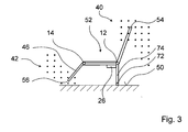
- Discrete spatial points 32, 34, 36, 38 are stored in the data memory which completely define a working space 40 ( FIG. 3 ).
- the discrete points in space 32, 34, 36, 38 are arranged at different locations in space. For reasons of clarity, only four of the spatial points are provided with reference numerals.
- the working space is shown in two dimensions. The working space is not limited to a two-dimensional space, but can be used for any three-dimensional movement of a seat part.
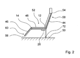
- FIG. 2 shows a passenger seat with a seat device according to the invention.
- the seat part 46 is freely movable.
- the seat part 44 is as a backrest, the seat part 46 is formed as a leg rest.
- the seat part 44 is freely movable.
- Both seat parts 44, 46 are pivotally mounted on the seat bottom 48 and may be pivoted by the seat actuators 12, 14 disposed within the seat bottom 48.
- Each seat part 44, 46 has an operating point 54, 56 which is stationary relative to the respective seat part 44, 46.
- the computing unit 18 determines the positions of the operating points 54, 56 on the basis of the geometry and the positions of the seat actuators 12, 14.
- the operating points 54, 56 are arranged in end regions 58, 60 of the seat parts 44, 46.
- Another seat actuator 72 is arranged on the Aufmenrebene 50.
- the seat actuator 72 moves a seat portion 74 to which the seat bottom 48 is attached.
- the seat bottom 48, as well as the other seat actuators 12, 14 move in an adjustment of the seat actuator 72 on circular paths around the seat actuator 72nd
- FIG. 4 schematically shows a section of the working space 40 with the operating point 54 of the seat portion 44.
- the working space 40 is completely defined by the space points 32, 34, 36, 38.
- the operating point 54 to a nearest room point 32 always has a distance 62 which is smaller than a defined maximum distance 64.
- a defined maximum distance 64 For each space point 32, 34, 36, 38 an individual maximum distance is stored. In the illustrated embodiment, all maximum distances are the same size.
- the maximum distance 64 defines a circular tolerance range around each spatial point 32, 34, 36, 38.
- the maximum distance 64 to a spatial point 32, 34, 36, 38 is smaller than a distance of the spatial point 32, 34, 36, 38 to a nearest, adjacent one Space point 32, 34, 36, 38.
- the operating point 54 is connected via the seat part 44 with the seat actuator 12.
- a rotation of the seat actuator 12 causes a movement of the operating point 54 on a circular path 66.
- the arithmetic unit 18 determines the position of the operating point 54 based on the length of the seat part 44 and an instantaneous angle of rotation of the seat actuator 12.
- an operating position 68 of the Wegaktuators 12 is stored, which is driven to assume a rest position.
- the control unit 10 calculates a travel path 70 of the operating point 54 to the operating position 68.
- the travel path 70 is predetermined by the circular path 66 of the seat actuator 12 and the position of the seat actuator 72. This creates a chain of seat actuators 12, 14, 72 which interact with each other.
- the travel path 70 can thus be chosen freely. If only the seat actuator 72 is adjusted, the operating points 54, 56 move in a circular path around the seat actuator 72.
- the control unit 10 controls the seat actuator 40, 42 associated with the seat actuator 12 as required. 14 on.
- the seat actuator 12, 14 then performs an evasive movement.
- the seat actuator 72 does not move in the illustrated embodiment.
- the travel path 70 therefore runs along the circular path 66 and has no kinks or corners.
- the control unit 10 cyclically calculates the travel path 70 as a function of a distance determination to a nearest spatial point 36, 38. If the distance determination results in a distance 62 that is smaller than the maximum distance 64, the operating point 54 is located within the working space 40.
- the control unit 10 calculates the travel path 70 in a pre-simulation. In this case, possible traverse paths are checked for collision risks and adjusted in such a way that collisions of the seat part 44 are avoided.
- a starting and braking of the seat actuators 12, 14 takes place according to a travel curve, which is calculated by the arithmetic unit 18 of the control unit 10.
- a speed parameter is stored for each spatial point 32, 34, 36, 38, which determines with which speed a seat part 44 is to pass the spatial point 32, 34, 36, 38.
- the Verfahrkurve describes an acceleration behavior or speed values of the operating point 54, which are achieved by a targeted rotational speed of the seat actuators 12, 14.
- the Verfahrkurve describes an acceleration behavior or speed values of the operating point 54, which are achieved by a targeted rotational speed of the seat actuators 12, 14.
- With an adjustment of both seat actuators 12, 14 calculates the arithmetic unit 18 of the control unit 10 for each seat actuator 12, 14 a trajectory, so that both seat actuators 12, 14 start time-synchronously and decelerate synchronously.
- the sensor unit 28 provides information about possible objects that are located within the workspace 40. If the sensor unit 28 displays an object, the arithmetic unit 18 recalculates the travel path 70 accordingly and can thus avoid a possible collision of the seat parts 44, 46 with the object. As a result, the sensor unit 28 changes the travel path 70 as a function of a disturbing object.
Landscapes
- Engineering & Computer Science (AREA)
- Aviation & Aerospace Engineering (AREA)
- Seats For Vehicles (AREA)
Abstract
Description
- Die Erfindung geht aus von einer Sitzvorrichtung, insbesondere einer Fluggastsitzvorrichtung, mit zumindest einer Kontrolleinheit, die zur Ansteuerung zumindest eines Sitzaktuators in einem Arbeitsraum vorgesehen ist.
- Es ist bereits eine Sitzvorrichtung, insbesondere eine Fluggastsitzvorrichtung, mit zumindest einer Kontrolleinheit, die zur Ansteuerung zumindest eines Sitzaktuators in einem Arbeitsraum vorgesehen ist, bekannt. Der Arbeitsraum ist durch eine Hüllkurve begrenzt und beschreibt einen Raum, in dem sich der Sitzaktuator bewegt.
- Der Erfindung liegt insbesondere die Aufgabe zugrunde, eine gattungsgemäße Sitzvorrichtung bereitzustellen, durch die ein Passagierkomfort vor allem bei einer Sitzverstellung erhöht werden kann.
- Diese Aufgabe ist durch eine Sitzvorrichtung gemäß dem Patentanspruch 1 gelöst. Weitere vorteilhafte Ausführungen der Erfindung können den Unteransprüchen entnommen werden.
- Die Erfindung geht aus von einer Sitzvorrichtung, insbesondere einer Fluggastsitzvorrichtung, mit zumindest einer Kontrolleinheit, die zur Ansteuerung zumindest eines Sitzaktuators in einem Arbeitsraum vorgesehen ist.
- Es wird vorgeschlagen, dass in der Kontrolleinheit diskrete Raumpunkte gespeichert sind, die den Arbeitsraum vollständig definieren, wodurch die Kontrolleinheit eine mögliche Sitzaktuatoransteuerung besonders schnell berechnen kann und wodurch eine Bewegung des Sitzaktuators vorteilhaft einfach entlang der Raumpunkte erfolgen kann. Kollisionen des Sitzaktuators können somit schnell vorausberechnet und vermieden werden, was zu einem erhöhten Sitzkomfort führen kann. Unter einer "Kontrolleinheit" soll dabei in diesem Zusammenhang insbesondere eine Einheit verstanden werden, die eine Datenspeichereinheit und eine Recheneinheit aufweist und dazu vorgesehen ist, zumindest einen Sitzaktuator anzusteuern. Unter einer "Datenspeichereinheit" soll insbesondere eine Einheit verstanden werden, die dazu vorgesehen ist, zumindest eine Information, vorteilhaft von einer Stromversorgung unabhängig, zu speichern. Unter einer "Recheneinheit" soll insbesondere eine Einheit mit einem Informationseingang, einer Informationsverarbeitung und einer Informationsausgabe verstanden werden. Vorteilhaft weist die Recheneinheit zumindest einen Prozessor, Ein- und Ausgabemittel, weitere elektrische Bauteile, ein Betriebsprogramm, Regelroutinen, Steuerroutinen und/oder Berechnungsroutinen auf. Vorzugsweise sind die Bauteile der Recheneinheit auf einer gemeinsamen Platine angeordnet und/oder vorteilhaft in einem gemeinsamen Gehäuse angeordnet. Unter einem "Sitzaktuator" soll in diesem Zusammenhang insbesondere ein Antriebselement verstanden werden, das dazu vorgesehen ist, zumindest ein Sitzteil relativ zu einem weiteren Sitzteil und/oder zu einer Sitzumgebung zu bewegen. Das Antriebselement kann dabei insbesondere elektrisch und/oder pneumatisch arbeiten und dabei eine Linearbewegung und/oder eine Rotationsbewegung ausführen. Unter einem "Arbeitsraum" soll in diesem Zusammenhang ein definierter Raum verstanden werden, in dem bestimmte Sitzteile bewegt werden können. Der Arbeitsraum kann statisch oder bevorzugt zumindest teilweise veränderbar ausgebildet sein. Unter "diskreten Raumpunkten" soll in diesem Zusammenhang insbesondere eine definierte Anzahl an Referenzpunkten verstanden werden, die bevorzugt an unterschiedlichen Orten angeordnet sind. Bevorzugt ist für zumindest einen Raumpunkt ein Geschwindigkeitsparameter gespeichert, der festlegt, mit welcher Geschwindigkeit ein Sitzteil den Raumpunkt passieren soll.
- In einer weiteren Ausgestaltung der Erfindung wird vorgeschlagen, dass die Kontrolleinheit dazu vorgesehen ist, einen Arbeitspunkt des zumindest einen Sitzaktuators zu berechnen, wodurch eine besonders einfache und präzise Positionsbestimmung des Sitzaktuators erreicht werden kann. Unter "vorgesehen" soll insbesondere speziell programmiert, ausgelegt und/oder ausgestattet verstanden werden.
- Ferner wird vorgeschlagen, dass der Arbeitspunkt zu einem nächstliegenden Raumpunkt stets einen Abstand aufweist, der kleiner ist als ein definierter Maximalabstand, wodurch der Arbeitsraum besonders einfach durch die Raumpunkte definiert werden kann. Unter einem Maximalabstand soll in diesem Zusammenhang insbesondere ein Abstand verstanden werden, der einen Toleranzbereich um einen Raumpunkt definiert. Bevorzugt ist der Maximalabstand zu einem Raumpunkt kleiner als der Abstand des Raumpunkts zu einem nächstliegenden, benachbarten Raumpunkt. Bevorzugt ist für zumindest einen Raumpunkt ein individueller Maximalabstand gespeichert.
- Ist die Kontrolleinheit dazu vorgesehen, zumindest eine Betriebsposition des zumindest einen Sitzaktuators zu speichern, kann ein Sitzaktuator vorteilhaft besonders schnell in eine gewünschte Stellung gefahren werden und/oder der Sitzkomfort weiter erhöht werden. Unter einer "Betriebsposition" soll in diesem Zusammenhang insbesondere eine vordefinierte Sitzposition verstanden werden, die insbesondere bei einem Start-oder Landevorgang, bei Turbulenzen, zum Ausruhen, zum Essen oder zum Lesen angesteuert werden kann.
- Ferner wird vorgeschlagen, dass die Kontrolleinheit dazu vorgesehen ist, bei einer Ansteuerung des zumindest einen Sitzaktuators einen Verfahrweg zu berechnen, wodurch der Verfahrweg bei jeder Ansteuerung spezifisch festgelegt und/oder ein flüssiger, weicher Verfahrweg erreicht werden kann. Unter einem "Verfahrweg" soll dabei in diesem Zusammenhang insbesondere eine Fahrkurve verstanden werden, auf der sich ein fester Bezugspunkt des Sitzaktuators bei einer Ansteuerung des Sitzaktuators bewegt. Vorteilhaft weist der Verfahrweg keine Knicke oder Ecken auf.
- Es wird weiter vorgeschlagen, dass die Kontrolleinheit dazu vorgesehen ist, den Verfahrweg in Abhängigkeit von zumindest einer Abstandsbestimmung zu zumindest einem nächstliegenden Raumpunkt zu berechnen. Dadurch kann der Verfahrweg auf einfache Weise an den Arbeitsraum angepasst und/oder ein Verlassen des zumindest einen Sitzaktuators aus dem Arbeitsraum vorteilhaft vermieden werden.
- In einer weiteren Ausgestaltung der Erfindung wird vorgeschlagen, dass die Kontrolleinheit dazu vorgesehen ist, den Verfahrweg in einer Vorsimulation zu berechnen. Eine mögliche Kollision des zumindest einen Sitzaktuators mit einem weiteren Bauteil und/oder ein Verlassen des Arbeitsraums kann dadurch vorteilhaft frühzeitig erkannt und vermieden werden. Ferner kann durch die Vorsimulation eine Ausgleichsbewegung des zumindest einen Sitzaktuators erreicht werden, was zu einem erhöhten Sitzkomfort führen und/oder ein abruptes Stoppen der Sitzaktuatoren vermeiden kann.
- Der Sitzkomfort kann weiter gesteigert werden, wenn die Kontrolleinheit dazu vorgesehen ist, den zumindest einen Sitzaktuator bei einer Gesamtbewegung zeitsynchron mit zumindest einem weiteren Sitzaktuator anzusteuern. Dadurch können ein Anfahren und ein Abbremsen aller Sitzaktuatoren gleichzeitig erfolgen, was zu einem erhöhten Sitzkomfort führen kann. Unter "zeitsynchron" soll in diesem Zusammenhang zeitgleich verstanden werden.
- In einer weiteren Ausgestaltung der Erfindung wird vorgeschlagen, dass die Kontrolleinheit dazu vorgesehen ist, für den zumindest einen Sitzaktuator eine Verfahrkurve zu berechnen. Dadurch kann jeder Sitzaktuator vorteilhaft mit einem eigenen Geschwindigkeitsverlauf angesteuert werden. Unter einer "Verfahrkurve" soll in diesem Zusammenhang insbesondere ein Datensatz verstanden werden, der Geschwindigkeitsverläufe und/oder Beschleunigungsverläufe von Sitzaktuatoren beschreibt. Bevorzugt berechnet die Kontrolleinheit die Verfahrkurve insbesondere aus den Raumpunkten, dem Verfahrweg, den Geschwindigkeitsparametern der Raumpunkte und/oder den individuellen Maximalabständen der Raumpunkte.
- Weist die Kontrolleinheit eine Sensoreinheit auf, die dazu vorgesehen ist, den Verfahrweg zu verändern, können Gegenstände oder Hindernisse innerhalb des Arbeitsraums erkannt und der Arbeitsraum verändert werden, was Kollisionen von Sitzteilen vermeiden kann.
- Weitere Vorteile ergeben sich aus der folgenden Zeichnungsbeschreibung. In der Zeichnung ist ein Ausführungsbeispiel der Erfindung dargestellt. Die Beschreibung und die Ansprüche enthalten zahlreiche Merkmale in Kombination. Der Fachmann wird die Merkmale zweckmäßigerweise auch einzeln betrachten und zu sinnvollen weiteren Kombinationen zusammenfassen.
-
- Fig. 1
- einen Aufbau einer Sitzvorrichtung,
- Fig. 2
- eine Seitenansicht eines Fluggastsitzes mit der Sitzvorrichtung nach
Figur 1 , - Fig. 3
- eine Seitenansicht des Fluggastsitzes mit der Sitzvorrichtung nach
Figur 2 mit einem Arbeitsraum und - Fig. 4
- einen Ausschnitt des Arbeitsraums nach
Figur 3 . -
Figur 1 zeigt eine schematische Ansicht einer Sitzvorrichtung mit einer Kontrolleinheit 10, die zwei Sitzaktuatoren 12, 14 ansteuert. Die Sitzaktuatoren 12, 14 sind als Servoelemente ausgebildet, die jeweils ein Sitzteil 44, 46 relativ zu einem Sitzboden 48 und zu einer Aufständerebene 50 eines Fluggastsitzes 52 bewegen (Figur 2 ). - Die Sitzaktuatoren 12, 14 arbeiten dabei elektrisch und führen eine Rotationsbewegung der Sitzteile 44, 46 aus. Es ist in diesem Zusammenhang jedoch auch denkbar, dass ein Fachmann pneumatische Sitzaktuatoren einsetzt und/oder die Sitzaktuatoren eine Linearbewegung ausführen. Die Kontrolleinheit 10 wird von einer externen Energiequelle (nicht dargestellt) mit einer elektrischen Spannung versorgt.
- Die Kontrolleinheit 10 weist eine Datenspeichereinheit 16 und eine Recheneinheit 18 auf. Die Datenspeichereinheit 16 speichert unabhängig von einer Stromversorgung Informationen in einem Datenspeicher 30. Die Recheneinheit 18 weist einen Informationseingang 20, eine Informationsverarbeitung 22 und eine Informationsausgabe 24 auf.
- Ferner weist die Recheneinheit 18 einen Prozessor, Ein- und Ausgabemittel, weitere elektrische Bauteile, ein Betriebsprogramm, Regelroutinen, Steuerroutinen und Berechnungsroutinen auf (nicht dargestellt). Die Bauteile der Recheneinheit 18 sind auf einer gemeinsamen Platine (nicht dargestellt) und in einem gemeinsamen Gehäuse 26 angeordnet. Das Gehäuse 26 ist am Sitzboden 48 angeordnet. Es ist in diesem Zusammenhang jedoch auch denkbar, das Gehäuse 26 außerhalb eines Fluggastsitzes anzuordnen.
- Am Informationseingang 20 ist eine Sensoreinheit 28 der Kontrolleinheit 10 angeschlossen. Die Sensoreinheit 28 ist von einer Lichtschranke gebildet. Es sind in diesem Zusammenhang auch andere, dem Fachmann als sinnvoll erscheinende Sensorelemente denkbar, wie zum Beispiel Bewegungssensoren, Temperatursensoren, Beschleunigungssensoren, Schallsensoren, Drucksensoren und/oder Feuchtigkeitssensoren.
- Im Datenspeicher sind diskrete Raumpunkte 32, 34, 36, 38 gespeichert, die einen Arbeitsraum 40 vollständig definieren (
Figur 3 ). Die diskreten Raumpunkte 32, 34, 36, 38 sind an unterschiedlichen Orten im Raum angeordnet. Aus Gründen der Übersichtlichkeit sind nur vier der Raumpunkte mit Bezugszeichen versehen. Ferner ist der Arbeitsraum zweidimensional dargestellt. Der Arbeitsraum ist jedoch nicht auf einen zweidimensionalen Raum beschränkt, sondern kann für jede beliebige dreidimensionale Bewegung eines Sitzteils verwendet werden. -
Figur 2 zeigt einen Fluggastsitz mit einer erfindungsgemäßen Sitzvorrichtung. Innerhalb des Arbeitsraums 40 ist das Sitzteil 46 frei bewegbar. Das Sitzteil 44 ist als Rückenlehne, das Sitzteil 46 als Beinauflage ausgebildet. In einem weiteren Arbeitsraum 42 ist das Sitzteil 44 frei bewegbar. - Beide Sitzteile 44, 46 sind schwenkbar am Sitzboden 48 gelagert und können von den Sitzaktuatoren 12, 14, die innerhalb des Sitzbodens 48 angeordnet sind, geschwenkt werden. Jedes Sitzteil 44, 46 weist einen Arbeitspunkt 54, 56 auf, der zum jeweiligen Sitzteil 44, 46 ortsfest angeordnet ist. Die Recheneinheit 18 bestimmt die Positionen der Arbeitspunkte 54, 56 anhand der Geometrie und der Stellungen der Sitzaktuatoren 12, 14. Die Arbeitspunkte 54, 56 sind in Endbereichen 58, 60 der Sitzteile 44, 46 angeordnet.
- Ein weiterer Sitzaktuator 72 ist an der Aufständerebene 50 angeordnet. Der Sitzaktuator 72 bewegt ein Sitzteil 74, an dem der Sitzboden 48 befestigt ist. Der Sitzboden 48, sowie die anderen Sitzaktuatoren 12, 14 bewegen sich bei einer Verstellung des Sitzaktuators 72 auf Kreisbahnen um den Sitzaktuator 72.
-
Figur 4 zeigt schematisch einen Ausschnitt des Arbeitsraums 40 mit dem Arbeitspunkt 54 des Sitzteils 44. Der Arbeitsraum 40 wird von den Raumpunkten 32, 34, 36, 38 vollständig definiert. Dazu weist der Arbeitspunkt 54 zu einem nächstliegenden Raumpunkt 32 stets einen Abstand 62 auf, der kleiner ist als ein definierter Maximalabstand 64. Für jeden Raumpunkt 32, 34, 36, 38 ist ein individueller Maximalabstand gespeichert. Im gezeigten Ausführungsbeispiel sind alle Maximalabstände gleich groß. - Der Maximalabstand 64 definiert einen kreisförmigen Toleranzbereich um jeden Raumpunkt 32, 34, 36, 38. Der Maximalabstand 64 zu einem Raumpunkt 32, 34, 36, 38 ist kleiner als ein Abstand des Raumpunkts 32, 34, 36, 38 zu einem nächstliegenden, benachbarten Raumpunkt 32, 34, 36, 38.
- Wie
Figur 4 weiter zeigt, ist der Arbeitspunkt 54 über das Sitzteil 44 mit dem Sitzaktuator 12 verbunden. Eine Rotation des Sitzaktuators 12 bewirkt eine Bewegung des Arbeitspunkts 54 auf einer Kreisbahn 66. Die Recheneinheit 18 bestimmt die Position des Arbeitspunkts 54 anhand der Länge des Sitzteils 44 und eines momentanen Drehwinkels des Sitzaktuators 12. - In der Datenspeichereinheit 16 der Kontrolleinheit 10 ist eine Betriebsposition 68 des Sitzaktuators 12 gespeichert, die zur Einnahme einer Ruheposition angesteuert wird. Zur Ansteuerung des Sitzaktuators 12 berechnet die Kontrolleinheit 10 einen Verfahrweg 70 des Arbeitspunkts 54 zur Betriebsposition 68.
- Im gezeigten Ausführungsbeispiel ist der Verfahrweg 70 durch die Kreisbahn 66 des Sitzaktuators 12 und die Stellung des Sitzaktuators 72 vorgegeben. Dadurch entsteht eine Kette von Sitzaktuatoren 12, 14, 72, die in Wechselwirkung zueinander stehen. Der Verfahrweg 70 kann somit frei gewählt werden. Wird nur der Sitzaktuator 72 verstellt, bewegen sich die Arbeitspunkte 54, 56 auf einer Kreisbahn um den Sitzaktuator 72. Um ein Verlassen des Arbeitsraums 40, 42 zu vermeiden, steuert die Kontrolleinheit 10 nach Bedarf den zum jeweiligen Arbeitsraum 40, 42 zugehörigen Sitzaktuator 12, 14 an. Der Sitzaktuator 12, 14 führt daraufhin eine Ausweichbewegung aus. Zur Vereinfachung bewegt sich der Sitzaktuator 72 im gezeigten Ausführungsbeispiel nicht. Der Verfahrweg 70 verläuft daher entlang der Kreisbahn 66 und weist keine Knicke oder Ecken auf.
- Die Kontrolleinheit 10 berechnet zyklisch den Verfahrweg 70 in Abhängigkeit von einer Abstandsbestimmung zu einem nächstliegenden Raumpunkt 36, 38. Ergibt die Abstandsbestimmung einen Abstand 62, der kleiner ist als der Maximalabstand 64, befindet sich der Arbeitspunkt 54 innerhalb des Arbeitsraums 40. Die Kontrolleinheit 10 berechnet den Verfahrweg 70 in einer Vorsimulation. Dabei werden mögliche Verfahrwege auf Kollisionsgefahren hin überprüft und derart angepasst, dass Kollisionen des Sitzteils 44 vermieden werden.
- Ein Anfahren und Abbremsen der Sitzaktuatoren 12, 14 erfolgt gemäß einer Verfahrkurve, die von der Recheneinheit 18 der Kontrolleinheit 10 berechnet wird. Zur Berechnung der Verfahrkurve ist für jeden Raumpunkt 32, 34, 36, 38 ein Geschwindigkeitsparameter gespeichert, der festlegt, mit welcher Geschwindigkeit ein Sitzteil 44 den Raumpunkt 32, 34, 36, 38 passieren soll.
- Die Verfahrkurve beschreibt ein Beschleunigungsverhalten bzw. Geschwindigkeitswerte des Arbeitspunkts 54, die durch eine gezielte Rotationsgeschwindigkeit der Sitzaktuatoren 12, 14 erreicht werden. Bei einer Verstellung beider Sitzaktuatoren 12, 14 berechnet die Recheneinheit 18 der Kontrolleinheit 10 für jeden Sitzaktuator 12, 14 eine Verfahrkurve, so dass beide Sitzaktuatoren 12, 14 zeitsynchron anfahren und zeitsynchron abbremsen.
- Die Sensoreinheit 28 liefert Informationen über mögliche Gegenstände, die sich innerhalb des Arbeitsraums 40 befinden. Zeigt die Sensoreinheit 28 einen Gegenstand an, berechnet die Recheneinheit 18 den Verfahrweg 70 entsprechend neu und kann somit eine mögliche Kollision der Sitzteile 44, 46 mit dem Gegenstand vermeiden. Dadurch verändert die Sensoreinheit 28 den Verfahrweg 70 in Abhängigkeit von einem störenden Gegenstand.
-
- 10
- Kontrolleinheit
- 12
- Sitzaktuator
- 14
- Sitzaktuator
- 16
- Datenspeichereinheit
- 18
- Recheneinheit
- 20
- Informationseingang
- 22
- Informationsverarbeitung
- 24
- Informationsausgabe
- 26
- Gehäuse
- 28
- Sensoreinheit
- 30
- Datenspeicher
- 32
- Raumpunkt
- 34
- Raumpunkt
- 36
- Raumpunkt
- 38
- Raumpunkt
- 40
- Arbeitsraum
- 42
- Arbeitsraum
- 44
- Sitzteil
- 46
- Sitzteil
- 48
- Sitzboden
- 50
- Aufständerebene
- 52
- Fluggastsitz
- 54
- Arbeitspunkt
- 56
- Arbeitspunkt
- 58
- Endbereich
- 60
- Endbereich
- 62
- Abstand
- 64
- Maximalabstand
- 66
- Kreisbahn
- 68
- Betriebsposition
- 70
- Verfahrweg
- 72
- Sitzaktuator
- 74
- Sitzteil
Claims (11)
- Sitzvorrichtung, insbesondere Fluggastsitzvorrichtung, mit zumindest einer Kontrolleinheit (10), die zur Ansteuerung zumindest eines Sitzaktuators (12, 14) in einem Arbeitsraum (40) vorgesehen ist, dadurch gekennzeichnet, dass in der Kontrolleinheit (10) diskrete Raumpunkte (32, 34, 36, 38) gespeichert sind, die den Arbeitsraum (40) vollständig definieren.
- Sitzvorrichtung nach Anspruch 1, dadurch gekennzeichnet, dass die Kontrolleinheit (10) dazu vorgesehen ist, einen Arbeitspunkt (54, 56) des zumindest einen Sitzaktuators (12, 14) zu berechnen.
- Sitzvorrichtung nach Anspruch 2, dadurch gekennzeichnet, dass der Arbeitspunkt (54, 56) zu einem nächstliegenden Raumpunkt (32, 34, 36, 38) stets einen Abstand (62) aufweist, der kleiner ist als ein definierter Maximalabstand (64).
- Sitzvorrichtung nach einem der vorhergehenden Ansprüche, dadurch gekennzeichnet, dass die Kontrolleinheit (10) dazu vorgesehen ist, zumindest eine Betriebsposition (68) des zumindest einen Sitzaktuators (12, 14) zu speichern.
- Sitzvorrichtung nach einem der vorhergehenden Ansprüche, dadurch gekennzeichnet, dass die Kontrolleinheit (10) dazu vorgesehen ist, bei einer Ansteuerung des zumindest einen Sitzaktuators (12, 14) einen Verfahrweg (70) zu berechnen.
- Sitzvorrichtung nach Anspruch 5, dadurch gekennzeichnet, dass die Kontrolleinheit (10) dazu vorgesehen ist, den Verfahrweg (70) in Abhängigkeit von zumindest einer Abstandsbestimmung zu zumindest einem nächstliegenden Raumpunkt (32, 34, 36, 38) zu berechnen.
- Sitzvorrichtung zumindest nach Anspruch 5, dadurch gekennzeichnet, dass die Kontrolleinheit (10) dazu vorgesehen ist, den Verfahrweg (70) in einer Vorsimulation zu berechnen.
- Sitzvorrichtung nach einem der vorhergehenden Ansprüche, dadurch gekennzeichnet, dass die Kontrolleinheit (10) dazu vorgesehen ist, den zumindest einen Sitzaktuator (14) bei einer Gesamtbewegung zeitsynchron mit zumindest einem weiteren Sitzaktuator (12) anzusteuern.
- Sitzvorrichtung nach einem der vorhergehenden Ansprüche, dadurch gekennzeichnet, dass die Kontrolleinheit (10) dazu vorgesehen ist, für den zumindest einen Sitzaktuator (12, 14) eine Verfahrkurve zu berechnen.
- Sitzvorrichtung zumindest nach Anspruch 5, dadurch gekennzeichnet, dass die Kontrolleinheit (10) eine Sensoreinheit (28) aufweist, die dazu vorgesehen ist, den Verfahrweg (70) zu verändern.
- System mit einer Sitzvorrichtung nach einem der vorhergehenden Ansprüche, einem Fluggastsitz und mit zumindest einem Sitzaktuator (12, 14).
Applications Claiming Priority (1)
| Application Number | Priority Date | Filing Date | Title |
|---|---|---|---|
| DE102011014723A DE102011014723A1 (de) | 2011-03-23 | 2011-03-23 | Sitzvorrichtung, insbesondere Fluggastsitzvorrichtung |
Publications (2)
| Publication Number | Publication Date |
|---|---|
| EP2502827A1 true EP2502827A1 (de) | 2012-09-26 |
| EP2502827B1 EP2502827B1 (de) | 2013-09-25 |
Family
ID=45887893
Family Applications (1)
| Application Number | Title | Priority Date | Filing Date |
|---|---|---|---|
| EP12001760.3A Active EP2502827B1 (de) | 2011-03-23 | 2012-03-15 | Sitzvorrichtung, insbesondere Fluggastsitzvorrichtung |
Country Status (2)
| Country | Link |
|---|---|
| EP (1) | EP2502827B1 (de) |
| DE (1) | DE102011014723A1 (de) |
Families Citing this family (1)
| Publication number | Priority date | Publication date | Assignee | Title |
|---|---|---|---|---|
| DE102020116860A1 (de) | 2020-06-26 | 2021-12-30 | Audi Aktiengesellschaft | Kraftfahrzeugsitzanordnung und Kraftfahrzeug |
Citations (3)
| Publication number | Priority date | Publication date | Assignee | Title |
|---|---|---|---|---|
| FR2821252A1 (fr) * | 2001-02-27 | 2002-08-30 | Labinal | Siege a parties mobiles |
| US20080007101A1 (en) * | 2006-06-20 | 2008-01-10 | Hans-Dieter Abt | Vehicle seat and method for moving the vehicle seat in a vehicle cabin |
| EP2279897A1 (de) * | 2009-07-31 | 2011-02-02 | Precilec | Steuerverfahren der Kinematik eines Sitzes mit beweglichen Teilen gemäß des Freiraums, und Sitz, bei dem dieses Verfahren umgesetzt wird |
Family Cites Families (6)
| Publication number | Priority date | Publication date | Assignee | Title |
|---|---|---|---|---|
| US5670853A (en) * | 1994-12-06 | 1997-09-23 | Trw Vehicle Safety Systems Inc. | Method and apparatus for controlling vehicle occupant position |
| DE10107195A1 (de) * | 2001-02-16 | 2002-09-12 | Recaro Aircraft Seating Gmbh | Fahrzeugsitz, insbesondere Fluggastsitz |
| DE102005022818A1 (de) * | 2005-05-12 | 2006-11-16 | Sonja Bissbort | Fahrzeug- oder Flugzeugsitz-System |
| EP1870333A3 (de) * | 2006-06-20 | 2009-07-15 | Bühler Motor GmbH | Einstellsystem für Fahrzeugsitze oder Gruppen von Fahrzeugsitzen |
| DE102006029206B4 (de) * | 2006-06-20 | 2008-04-30 | Bühler Motor GmbH | Fahrzeugsitz und Verfahren zum Bewegen zumindest eines in einer Fahrzeugkabine angeordneten Fahrzeugsitzes, insbesondere Fluggastsitzes |
| DE102007055088B4 (de) * | 2007-11-16 | 2013-03-07 | Airbus Operations Gmbh | Sitz mit einem Sitzelement, Sitzanordnung und Verfahren zur Überwachung eines Sitzes |
-
2011
- 2011-03-23 DE DE102011014723A patent/DE102011014723A1/de not_active Withdrawn
-
2012
- 2012-03-15 EP EP12001760.3A patent/EP2502827B1/de active Active
Patent Citations (3)
| Publication number | Priority date | Publication date | Assignee | Title |
|---|---|---|---|---|
| FR2821252A1 (fr) * | 2001-02-27 | 2002-08-30 | Labinal | Siege a parties mobiles |
| US20080007101A1 (en) * | 2006-06-20 | 2008-01-10 | Hans-Dieter Abt | Vehicle seat and method for moving the vehicle seat in a vehicle cabin |
| EP2279897A1 (de) * | 2009-07-31 | 2011-02-02 | Precilec | Steuerverfahren der Kinematik eines Sitzes mit beweglichen Teilen gemäß des Freiraums, und Sitz, bei dem dieses Verfahren umgesetzt wird |
Also Published As
| Publication number | Publication date |
|---|---|
| DE102011014723A1 (de) | 2012-09-27 |
| EP2502827B1 (de) | 2013-09-25 |
Similar Documents
| Publication | Publication Date | Title |
|---|---|---|
| EP3359348B1 (de) | Robotersystem und verfahren zur steuerung eines robotersystems | |
| DE4291618C2 (de) | Computernumerisch-gesteuerte Maschine mit einer manuellen Bedieneinheit zur Steuerung eines programmierten Verfahrwegs | |
| EP1870334B1 (de) | Fahrzeugsitz, Einstellsystem und Verfahren zum Bewegen zumindest eines in einer Fahrzeugkabine angeordneten Fahrzeugsitzes, insbesondere Fluggastsitzes | |
| EP1996462B1 (de) | Sitzvorrichtung | |
| WO2008037491A1 (de) | Verfahren und system zur auslegung und überprüfung von sicherheitsbereichen eines roboters | |
| WO2018049447A1 (de) | Steuervorrichtung und steuerverfahren für industrielle maschinen mit gesteuerten bewegungsantrieben | |
| DE102017001298B4 (de) | Robotersimulationsvorrichtung, die einen überstrichenen Raum berechnet | |
| DE102012002303B4 (de) | Fahrerassistenzsystem für einen Kraftwagen, Kraftwagen und Verfahren zum Betreiben eines Fahrerassistenzsystems | |
| DE102016007995A1 (de) | Bedien- und Anzeigevorrichtung für ein Kraftfahrzeug, Verfahren zum Betreiben einer Bedien- und Anzeigevorrichtung für ein Kraftfahrzeug und Kraftfahrzeug mit einer Bedien- und Anzeigevorrichtung | |
| EP2124117A1 (de) | Bedieneinrichtung zur Bedienung einer Werkzeugmaschine | |
| EP3224849B1 (de) | Bedieneinrichtung und verfahren zum ansteuern von funktionseinheiten eines kraftfahrzeugs | |
| EP3556521B1 (de) | Bremswegüberwachung einer kinematik | |
| EP4078326A1 (de) | Steuerungsvorrichtung | |
| EP2502827B1 (de) | Sitzvorrichtung, insbesondere Fluggastsitzvorrichtung | |
| DE102012015143A1 (de) | Anordnung eines Roboters | |
| EP3343311A1 (de) | Bedienhebel mit aktiver rückmeldeeinheit | |
| DE102009027418A1 (de) | Elektromechanische Linearstelleinheit | |
| EP3130978B1 (de) | Bedieneinrichtung mit elektromechanischer haptischer rastfunktion | |
| WO2016184971A1 (de) | Verfahren zum betreiben einer bedienvorrichtung sowie bedienvorrichtung für ein kraftfahrzeug | |
| EP3366430B1 (de) | Fördervorrichtung zum befördern von objekten und/oder personen | |
| EP2639156B1 (de) | Sitzsteuerungsvorrichtung, insbesondere für einen Fluggastsitz | |
| DE102014002919A1 (de) | Bedienungseinrichtung und Kraftfahrzeugsitz | |
| WO2018060060A1 (de) | Verfahren zum betreiben von sich autonom bewegenden plattformen und hindernisschutzsensor | |
| EP3662345B1 (de) | Steuervorrichtung für industrielle maschinen | |
| EP3172421A1 (de) | Verfahren zur steuerung und/oder regelung der leistung eines motors |
Legal Events
| Date | Code | Title | Description |
|---|---|---|---|
| PUAI | Public reference made under article 153(3) epc to a published international application that has entered the european phase |
Free format text: ORIGINAL CODE: 0009012 |
|
| AK | Designated contracting states |
Kind code of ref document: A1 Designated state(s): AL AT BE BG CH CY CZ DE DK EE ES FI FR GB GR HR HU IE IS IT LI LT LU LV MC MK MT NL NO PL PT RO RS SE SI SK SM TR |
|
| AX | Request for extension of the european patent |
Extension state: BA ME |
|
| 17P | Request for examination filed |
Effective date: 20130218 |
|
| RIC1 | Information provided on ipc code assigned before grant |
Ipc: B64D 11/06 20060101AFI20130307BHEP |
|
| GRAP | Despatch of communication of intention to grant a patent |
Free format text: ORIGINAL CODE: EPIDOSNIGR1 |
|
| INTG | Intention to grant announced |
Effective date: 20130416 |
|
| GRAS | Grant fee paid |
Free format text: ORIGINAL CODE: EPIDOSNIGR3 |
|
| GRAA | (expected) grant |
Free format text: ORIGINAL CODE: 0009210 |
|
| AK | Designated contracting states |
Kind code of ref document: B1 Designated state(s): AL AT BE BG CH CY CZ DE DK EE ES FI FR GB GR HR HU IE IS IT LI LT LU LV MC MK MT NL NO PL PT RO RS SE SI SK SM TR |
|
| REG | Reference to a national code |
Ref country code: GB Ref legal event code: FG4D Free format text: NOT ENGLISH |
|
| REG | Reference to a national code |
Ref country code: CH Ref legal event code: EP |
|
| REG | Reference to a national code |
Ref country code: AT Ref legal event code: REF Ref document number: 633601 Country of ref document: AT Kind code of ref document: T Effective date: 20131015 |
|
| REG | Reference to a national code |
Ref country code: IE Ref legal event code: FG4D Free format text: LANGUAGE OF EP DOCUMENT: GERMAN |
|
| REG | Reference to a national code |
Ref country code: DE Ref legal event code: R096 Ref document number: 502012000135 Country of ref document: DE Effective date: 20131121 |
|
| PG25 | Lapsed in a contracting state [announced via postgrant information from national office to epo] |
Ref country code: SE Free format text: LAPSE BECAUSE OF FAILURE TO SUBMIT A TRANSLATION OF THE DESCRIPTION OR TO PAY THE FEE WITHIN THE PRESCRIBED TIME-LIMIT Effective date: 20130925 Ref country code: NO Free format text: LAPSE BECAUSE OF FAILURE TO SUBMIT A TRANSLATION OF THE DESCRIPTION OR TO PAY THE FEE WITHIN THE PRESCRIBED TIME-LIMIT Effective date: 20131225 Ref country code: LT Free format text: LAPSE BECAUSE OF FAILURE TO SUBMIT A TRANSLATION OF THE DESCRIPTION OR TO PAY THE FEE WITHIN THE PRESCRIBED TIME-LIMIT Effective date: 20130925 Ref country code: HR Free format text: LAPSE BECAUSE OF FAILURE TO SUBMIT A TRANSLATION OF THE DESCRIPTION OR TO PAY THE FEE WITHIN THE PRESCRIBED TIME-LIMIT Effective date: 20130925 |
|
| REG | Reference to a national code |
Ref country code: NL Ref legal event code: VDEP Effective date: 20130925 |
|
| REG | Reference to a national code |
Ref country code: LT Ref legal event code: MG4D |
|
| PG25 | Lapsed in a contracting state [announced via postgrant information from national office to epo] |
Ref country code: LV Free format text: LAPSE BECAUSE OF FAILURE TO SUBMIT A TRANSLATION OF THE DESCRIPTION OR TO PAY THE FEE WITHIN THE PRESCRIBED TIME-LIMIT Effective date: 20130925 Ref country code: GR Free format text: LAPSE BECAUSE OF FAILURE TO SUBMIT A TRANSLATION OF THE DESCRIPTION OR TO PAY THE FEE WITHIN THE PRESCRIBED TIME-LIMIT Effective date: 20131226 Ref country code: FI Free format text: LAPSE BECAUSE OF FAILURE TO SUBMIT A TRANSLATION OF THE DESCRIPTION OR TO PAY THE FEE WITHIN THE PRESCRIBED TIME-LIMIT Effective date: 20130925 Ref country code: SI Free format text: LAPSE BECAUSE OF FAILURE TO SUBMIT A TRANSLATION OF THE DESCRIPTION OR TO PAY THE FEE WITHIN THE PRESCRIBED TIME-LIMIT Effective date: 20130925 Ref country code: RS Free format text: LAPSE BECAUSE OF FAILURE TO SUBMIT A TRANSLATION OF THE DESCRIPTION OR TO PAY THE FEE WITHIN THE PRESCRIBED TIME-LIMIT Effective date: 20130925 |
|
| PG25 | Lapsed in a contracting state [announced via postgrant information from national office to epo] |
Ref country code: NL Free format text: LAPSE BECAUSE OF FAILURE TO SUBMIT A TRANSLATION OF THE DESCRIPTION OR TO PAY THE FEE WITHIN THE PRESCRIBED TIME-LIMIT Effective date: 20130925 Ref country code: EE Free format text: LAPSE BECAUSE OF FAILURE TO SUBMIT A TRANSLATION OF THE DESCRIPTION OR TO PAY THE FEE WITHIN THE PRESCRIBED TIME-LIMIT Effective date: 20130925 Ref country code: CZ Free format text: LAPSE BECAUSE OF FAILURE TO SUBMIT A TRANSLATION OF THE DESCRIPTION OR TO PAY THE FEE WITHIN THE PRESCRIBED TIME-LIMIT Effective date: 20130925 Ref country code: SK Free format text: LAPSE BECAUSE OF FAILURE TO SUBMIT A TRANSLATION OF THE DESCRIPTION OR TO PAY THE FEE WITHIN THE PRESCRIBED TIME-LIMIT Effective date: 20130925 Ref country code: IS Free format text: LAPSE BECAUSE OF FAILURE TO SUBMIT A TRANSLATION OF THE DESCRIPTION OR TO PAY THE FEE WITHIN THE PRESCRIBED TIME-LIMIT Effective date: 20140125 Ref country code: RO Free format text: LAPSE BECAUSE OF FAILURE TO SUBMIT A TRANSLATION OF THE DESCRIPTION OR TO PAY THE FEE WITHIN THE PRESCRIBED TIME-LIMIT Effective date: 20130925 |
|
| PG25 | Lapsed in a contracting state [announced via postgrant information from national office to epo] |
Ref country code: CY Free format text: LAPSE BECAUSE OF FAILURE TO SUBMIT A TRANSLATION OF THE DESCRIPTION OR TO PAY THE FEE WITHIN THE PRESCRIBED TIME-LIMIT Effective date: 20130925 Ref country code: PL Free format text: LAPSE BECAUSE OF FAILURE TO SUBMIT A TRANSLATION OF THE DESCRIPTION OR TO PAY THE FEE WITHIN THE PRESCRIBED TIME-LIMIT Effective date: 20130925 Ref country code: ES Free format text: LAPSE BECAUSE OF FAILURE TO SUBMIT A TRANSLATION OF THE DESCRIPTION OR TO PAY THE FEE WITHIN THE PRESCRIBED TIME-LIMIT Effective date: 20130925 |
|
| REG | Reference to a national code |
Ref country code: DE Ref legal event code: R097 Ref document number: 502012000135 Country of ref document: DE |
|
| PG25 | Lapsed in a contracting state [announced via postgrant information from national office to epo] |
Ref country code: PT Free format text: LAPSE BECAUSE OF FAILURE TO SUBMIT A TRANSLATION OF THE DESCRIPTION OR TO PAY THE FEE WITHIN THE PRESCRIBED TIME-LIMIT Effective date: 20140127 |
|
| PLBE | No opposition filed within time limit |
Free format text: ORIGINAL CODE: 0009261 |
|
| STAA | Information on the status of an ep patent application or granted ep patent |
Free format text: STATUS: NO OPPOSITION FILED WITHIN TIME LIMIT |
|
| PG25 | Lapsed in a contracting state [announced via postgrant information from national office to epo] |
Ref country code: IT Free format text: LAPSE BECAUSE OF FAILURE TO SUBMIT A TRANSLATION OF THE DESCRIPTION OR TO PAY THE FEE WITHIN THE PRESCRIBED TIME-LIMIT Effective date: 20130925 |
|
| 26N | No opposition filed |
Effective date: 20140626 |
|
| PG25 | Lapsed in a contracting state [announced via postgrant information from national office to epo] |
Ref country code: DK Free format text: LAPSE BECAUSE OF FAILURE TO SUBMIT A TRANSLATION OF THE DESCRIPTION OR TO PAY THE FEE WITHIN THE PRESCRIBED TIME-LIMIT Effective date: 20130925 |
|
| REG | Reference to a national code |
Ref country code: DE Ref legal event code: R097 Ref document number: 502012000135 Country of ref document: DE Effective date: 20140626 |
|
| PG25 | Lapsed in a contracting state [announced via postgrant information from national office to epo] |
Ref country code: LU Free format text: LAPSE BECAUSE OF FAILURE TO SUBMIT A TRANSLATION OF THE DESCRIPTION OR TO PAY THE FEE WITHIN THE PRESCRIBED TIME-LIMIT Effective date: 20140315 |
|
| REG | Reference to a national code |
Ref country code: IE Ref legal event code: MM4A |
|
| PG25 | Lapsed in a contracting state [announced via postgrant information from national office to epo] |
Ref country code: IE Free format text: LAPSE BECAUSE OF NON-PAYMENT OF DUE FEES Effective date: 20140315 |
|
| REG | Reference to a national code |
Ref country code: CH Ref legal event code: PL |
|
| PG25 | Lapsed in a contracting state [announced via postgrant information from national office to epo] |
Ref country code: CH Free format text: LAPSE BECAUSE OF NON-PAYMENT OF DUE FEES Effective date: 20150331 Ref country code: LI Free format text: LAPSE BECAUSE OF NON-PAYMENT OF DUE FEES Effective date: 20150331 |
|
| PG25 | Lapsed in a contracting state [announced via postgrant information from national office to epo] |
Ref country code: MT Free format text: LAPSE BECAUSE OF FAILURE TO SUBMIT A TRANSLATION OF THE DESCRIPTION OR TO PAY THE FEE WITHIN THE PRESCRIBED TIME-LIMIT Effective date: 20130925 |
|
| REG | Reference to a national code |
Ref country code: FR Ref legal event code: PLFP Year of fee payment: 5 |
|
| PG25 | Lapsed in a contracting state [announced via postgrant information from national office to epo] |
Ref country code: SM Free format text: LAPSE BECAUSE OF FAILURE TO SUBMIT A TRANSLATION OF THE DESCRIPTION OR TO PAY THE FEE WITHIN THE PRESCRIBED TIME-LIMIT Effective date: 20130925 |
|
| PG25 | Lapsed in a contracting state [announced via postgrant information from national office to epo] |
Ref country code: MC Free format text: LAPSE BECAUSE OF FAILURE TO SUBMIT A TRANSLATION OF THE DESCRIPTION OR TO PAY THE FEE WITHIN THE PRESCRIBED TIME-LIMIT Effective date: 20130925 |
|
| PG25 | Lapsed in a contracting state [announced via postgrant information from national office to epo] |
Ref country code: BG Free format text: LAPSE BECAUSE OF FAILURE TO SUBMIT A TRANSLATION OF THE DESCRIPTION OR TO PAY THE FEE WITHIN THE PRESCRIBED TIME-LIMIT Effective date: 20130925 |
|
| PG25 | Lapsed in a contracting state [announced via postgrant information from national office to epo] |
Ref country code: BE Free format text: LAPSE BECAUSE OF FAILURE TO SUBMIT A TRANSLATION OF THE DESCRIPTION OR TO PAY THE FEE WITHIN THE PRESCRIBED TIME-LIMIT Effective date: 20140331 Ref country code: HU Free format text: LAPSE BECAUSE OF FAILURE TO SUBMIT A TRANSLATION OF THE DESCRIPTION OR TO PAY THE FEE WITHIN THE PRESCRIBED TIME-LIMIT; INVALID AB INITIO Effective date: 20120315 Ref country code: TR Free format text: LAPSE BECAUSE OF FAILURE TO SUBMIT A TRANSLATION OF THE DESCRIPTION OR TO PAY THE FEE WITHIN THE PRESCRIBED TIME-LIMIT Effective date: 20130925 |
|
| GBPC | Gb: european patent ceased through non-payment of renewal fee |
Effective date: 20160315 |
|
| PG25 | Lapsed in a contracting state [announced via postgrant information from national office to epo] |
Ref country code: GB Free format text: LAPSE BECAUSE OF NON-PAYMENT OF DUE FEES Effective date: 20160315 |
|
| REG | Reference to a national code |
Ref country code: FR Ref legal event code: PLFP Year of fee payment: 6 |
|
| REG | Reference to a national code |
Ref country code: FR Ref legal event code: PLFP Year of fee payment: 7 |
|
| REG | Reference to a national code |
Ref country code: AT Ref legal event code: MM01 Ref document number: 633601 Country of ref document: AT Kind code of ref document: T Effective date: 20170315 |
|
| PG25 | Lapsed in a contracting state [announced via postgrant information from national office to epo] |
Ref country code: MK Free format text: LAPSE BECAUSE OF FAILURE TO SUBMIT A TRANSLATION OF THE DESCRIPTION OR TO PAY THE FEE WITHIN THE PRESCRIBED TIME-LIMIT Effective date: 20130925 |
|
| PG25 | Lapsed in a contracting state [announced via postgrant information from national office to epo] |
Ref country code: AT Free format text: LAPSE BECAUSE OF NON-PAYMENT OF DUE FEES Effective date: 20170315 |
|
| PG25 | Lapsed in a contracting state [announced via postgrant information from national office to epo] |
Ref country code: AL Free format text: LAPSE BECAUSE OF FAILURE TO SUBMIT A TRANSLATION OF THE DESCRIPTION OR TO PAY THE FEE WITHIN THE PRESCRIBED TIME-LIMIT Effective date: 20130925 |
|
| P01 | Opt-out of the competence of the unified patent court (upc) registered |
Effective date: 20230908 |
|
| PGFP | Annual fee paid to national office [announced via postgrant information from national office to epo] |
Ref country code: DE Payment date: 20260320 Year of fee payment: 15 |
|
| PGFP | Annual fee paid to national office [announced via postgrant information from national office to epo] |
Ref country code: FR Payment date: 20260324 Year of fee payment: 15 |