EP2501971B1 - Ventilstruktur für einen mikrofluidischen kanal - Google Patents
Ventilstruktur für einen mikrofluidischen kanal Download PDFInfo
- Publication number
- EP2501971B1 EP2501971B1 EP10796464.5A EP10796464A EP2501971B1 EP 2501971 B1 EP2501971 B1 EP 2501971B1 EP 10796464 A EP10796464 A EP 10796464A EP 2501971 B1 EP2501971 B1 EP 2501971B1
- Authority
- EP
- European Patent Office
- Prior art keywords
- channel
- valve structure
- appliance
- displacement
- pressing
- Prior art date
- Legal status (The legal status is an assumption and is not a legal conclusion. Google has not performed a legal analysis and makes no representation as to the accuracy of the status listed.)
- Not-in-force
Links
- 238000006073 displacement reaction Methods 0.000 claims description 38
- 238000003825 pressing Methods 0.000 claims description 38
- 239000000411 inducer Substances 0.000 claims description 8
- 239000012858 resilient material Substances 0.000 claims description 7
- 238000010276 construction Methods 0.000 description 8
- 238000000059 patterning Methods 0.000 description 8
- 238000004519 manufacturing process Methods 0.000 description 6
- 238000007596 consolidation process Methods 0.000 description 1
- 238000005520 cutting process Methods 0.000 description 1
- 230000003247 decreasing effect Effects 0.000 description 1
- 239000012467 final product Substances 0.000 description 1
- 238000003780 insertion Methods 0.000 description 1
- 230000037431 insertion Effects 0.000 description 1
- 238000009434 installation Methods 0.000 description 1
- 239000000463 material Substances 0.000 description 1
- 238000000053 physical method Methods 0.000 description 1
- 239000000126 substance Substances 0.000 description 1
Images



Classifications
-
- F—MECHANICAL ENGINEERING; LIGHTING; HEATING; WEAPONS; BLASTING
- F16—ENGINEERING ELEMENTS AND UNITS; GENERAL MEASURES FOR PRODUCING AND MAINTAINING EFFECTIVE FUNCTIONING OF MACHINES OR INSTALLATIONS; THERMAL INSULATION IN GENERAL
- F16K—VALVES; TAPS; COCKS; ACTUATING-FLOATS; DEVICES FOR VENTING OR AERATING
- F16K99/00—Subject matter not provided for in other groups of this subclass
- F16K99/0001—Microvalves
-
- B—PERFORMING OPERATIONS; TRANSPORTING
- B01—PHYSICAL OR CHEMICAL PROCESSES OR APPARATUS IN GENERAL
- B01L—CHEMICAL OR PHYSICAL LABORATORY APPARATUS FOR GENERAL USE
- B01L3/00—Containers or dishes for laboratory use, e.g. laboratory glassware; Droppers
- B01L3/50—Containers for the purpose of retaining a material to be analysed, e.g. test tubes
- B01L3/502—Containers for the purpose of retaining a material to be analysed, e.g. test tubes with fluid transport, e.g. in multi-compartment structures
- B01L3/5027—Containers for the purpose of retaining a material to be analysed, e.g. test tubes with fluid transport, e.g. in multi-compartment structures by integrated microfluidic structures, i.e. dimensions of channels and chambers are such that surface tension forces are important, e.g. lab-on-a-chip
- B01L3/502738—Containers for the purpose of retaining a material to be analysed, e.g. test tubes with fluid transport, e.g. in multi-compartment structures by integrated microfluidic structures, i.e. dimensions of channels and chambers are such that surface tension forces are important, e.g. lab-on-a-chip characterised by integrated valves
-
- F—MECHANICAL ENGINEERING; LIGHTING; HEATING; WEAPONS; BLASTING
- F16—ENGINEERING ELEMENTS AND UNITS; GENERAL MEASURES FOR PRODUCING AND MAINTAINING EFFECTIVE FUNCTIONING OF MACHINES OR INSTALLATIONS; THERMAL INSULATION IN GENERAL
- F16K—VALVES; TAPS; COCKS; ACTUATING-FLOATS; DEVICES FOR VENTING OR AERATING
- F16K99/00—Subject matter not provided for in other groups of this subclass
- F16K99/0001—Microvalves
- F16K99/0003—Constructional types of microvalves; Details of the cutting-off member
- F16K99/0026—Valves using channel deformation
-
- B—PERFORMING OPERATIONS; TRANSPORTING
- B01—PHYSICAL OR CHEMICAL PROCESSES OR APPARATUS IN GENERAL
- B01L—CHEMICAL OR PHYSICAL LABORATORY APPARATUS FOR GENERAL USE
- B01L2400/00—Moving or stopping fluids
- B01L2400/06—Valves, specific forms thereof
- B01L2400/0633—Valves, specific forms thereof with moving parts
- B01L2400/0655—Valves, specific forms thereof with moving parts pinch valves
Definitions
- the present invention relates to a valve structure for a microfluidic channel, where the valve serves the opening and closure of a channel on a second level raised through channel pillars from the plane of the microfluidic channel network at the first level of a base plate, and where the channel wall is formed of a resilient material.
- valve structure solutions are known for the opening and closure of microfluidic channels, for example in a way that a closing surface is pressed on one or more orifices inside of a widened part of the channel in order to close the channel.
- the channel needs to have a wider part, which is disadvantageous in many cases, e.g., too inhomogeneous flows may arise, furthermore, the displacement appliance may reach into the channel system, which may cause mechanical detachment difficulties.
- the aim of the invention is the construction of a valve capable of opening and closing the microfluidic channel, where the cross-section of the channel parts to be interconnected and to be detached is of a similar form and size as those of the channels at the first level of the channel system, and the actuation of the valve can be solved relatively easily, for example even in a manual way, furthermore, the valve can be reliably kept closed and opened later with a long lifetime, furthermore, the structure of the valve is simple.
- the invention is, accordingly, a valve structure for a microfluidic channel, where the valve serves the opening and closure of a channel on a second level raised through channel pillars from the plane of the microfluidic channel network at the first level of a base plate, and where the channel wall is formed of a resilient material, which valve structure consists of a base plate part, of protruding supporting walls belonging to the base plate and of a resilient part between the supporting walls, within which the channel is formed, and it consists furthermore of pressing appliances situated on the two sides of the channel wall, as well as of displacement appliances ensuring the movement of the pressing appliances in the direction of the mid-line of the channel.
- the supporting walls are situated in the form of an arc around the resilient part surrounding the channel.
- the form and size of the interior surfaces of the displacement appliance are shaped to suit the outside form and size of the pressing appliances, and by virtue of being mechanically suited to the pressing appliances, the displacement appliance, by its actuation, compels the pressing appliances to be shifted in a direction perpendicular to the channel and to compress the channel.
- the displacement appliance advantageously consists of a displacement inducer part moving the pressing appliance and of a handle ensuring a manual or other mechanical grip.
- the displacement appliance is expediently a cap-shaped body.
- the pressing appliance is an approximately cylindrical and/or parallelepiped shaped body, the axis of which is a by-passing perpendicular in relation to the axis of the channel.
- a cylindrical body we understand a circular cylindrical body or a body differing from it of a cross-section bounded by a curved line.
- a parallelepiped-shaped body we understand a parallelepiped of any kind of cross-section.
- cylinder and parallelepiped are combined within one body.
- pressing appliances of several shapes can be suitable for the invention to be constructed.
- the pressing appliance's side remote from the channel has a part constituting a form-lock with a part of the inner surface of the displacement appliance, preferably a protruding or a recessed part.
- the displacement appliance has its displacement inducer part of approximately the form of a ring, where the interior of the ring-shaped part has a part constituting a form-lock with the pressing appliance, preferably a recessed or a protruding part.
- a construction simplification is possible in case of which one pressing appliance or the two pressing appliances and the resilient part surrounding the channel are formed in one piece.
- the inner sides of the supporting walls are formed, in order for tight connection with the resilient part, preferably with uneven surfaces, for example, ribbed ones.
- interlocking appliances are located on the displacement appliance and the supporting wall, in order to fix the proper opening and closing position of the displacement appliance.
- valve structure according to the invention does not require siginificant change of any dimensions of the channels, it can be easily actuated without internal connection with the microfluidical system from the outside and relatively simply, also manually, furthermore, it is reliable, with long-lifetime, its structure is simple and easy to manufacture.
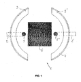
- FIG. 1 shows a detail of base plate 1, where on the first level of said base plate 1 a microfluidical channel network is constructed, which hereby is represented only with channel pieces 2,2', furthermore, Figure 1 shows the two, protruding supporting walls 3,3' belonging to said base plate 1, situated symmetrically, on which grooves 4 are located at the locations corresponding to the opening and closing positions of the displacement appliance 10.
- channel pillars 5, 5' In the top view the lower sections of channel pillars 5, 5' are visible, which channel pillars connect the channel pieces 2, 2' with the channel to be constructed at the second level.
- the base plate 1 will be formed from the same piece as the supporting walls 3, 3', but forming from separate pieces cannot be excluded, either.
- the lower sections of channel pillars 5, 5' were formed by piercing the base plate 1, while the channel pieces 2, 2' are formed at the first level of the base plate 1, at the lower surface of said base plate 1, and are connected to the channel network not represented here.
- the patterning structure of a shape of a converse flourishal arch necessary for ensuring the empty space in the final product along the resilient wall of the channel bearing a valve, to be constructed during the production, will be inserted through a rectangular cutting 6 of the base plate 1.
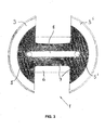
- the patterning structure of the shape of a converse flourishal arch and from above we insert a patterning body of a shape and size corresponding to the channel to be constructed, furthermore, we place above this a triumphal arch shaped patterning structure, away from the patterning body at a distance corresponding to the thickness of the channel wall, where the connecting foot parts of the flourishal arch shaped and converse flourishal arch shaped patterning structures adjoin to each other tightly.
- two half cylindrical, half parallelepiped shaped pressing appliances 9, 9' are placed to the zone of the resilient part 7 beside channel 8 , onto the base plate 1, symmetrically in relation to the channel 8, in a way presented in Figure 4 , where the height of said pressing appliances 9, 9' is approximately identical with the height of the supporting walls 3, 3', whereas its side remote from the channel 8 has a part constituting a form-lock with the displacement appliance 11, by means of a protruding edge 13, 13' of the parallelepiped.
- Figure 4 presents the displacement appliance 10 before being attached onto the valve, which is of a cap shape and consists of the displacement inducer part 11 capable of moving the pressing appliances 9, 9' in a direction perpendicular to channel 8, as well as, of a handle 12, e.g. for the purpose of manual operation.
- the displacement appliance 10 can be seen from underneath, whose displacement inducer part 11 is by and large ring-shaped, with recessed edges 15, 15' corresponding to the edges of the pressing appliances 9, 9'.
- displacement appliance 10 onto the supporting walls 3, 3' and the pressing appliances 9, 9' may take place in a position in which the edges on displacement appliance 10 and pressing appliance 9, 9' are overlapping.
- valve structure according to the invention may be realised in many embodiments different from those described in the examples above but still remaining within the scope and spirit of the present invention, therefore, our invention cannot be regarded as limited to the examples.
Landscapes
- Chemical & Material Sciences (AREA)
- Engineering & Computer Science (AREA)
- General Engineering & Computer Science (AREA)
- Dispersion Chemistry (AREA)
- Mechanical Engineering (AREA)
- Health & Medical Sciences (AREA)
- Hematology (AREA)
- General Health & Medical Sciences (AREA)
- Analytical Chemistry (AREA)
- Clinical Laboratory Science (AREA)
- Chemical Kinetics & Catalysis (AREA)
- Check Valves (AREA)
- Micromachines (AREA)
- Multiple-Way Valves (AREA)
- Automatic Analysis And Handling Materials Therefor (AREA)
- Lift Valve (AREA)
- Valve Housings (AREA)
Claims (12)
- Ventilstruktur für einen mikrofluidischen Kanal, wobei das Ventil zum Öffnen und Schliessen des Kanals dient, der sich in einer zweiten Ebene befindet, wobei die zweite Ebene aus einer, ein mikrofluidisches Kanalnetz in einer Grundplatte umfassenden ersten Ebene durch Kanalsäulen herausgehoben ist, und wobei die Wand des Kanals aus einem elastischen Material ausgebildet ist, dadurch gekennzeichnet, dass die Ventilstruktur aus einem Teil der Grundplatte (1), aus zur Grundplatte (1) gehörenen, herausragenden Stützwänden (3, 3'), aus einem, sich zwischen den Stützwänden (3, 3') befindenden elastischen Teil (7) besteht, in dem der Kanal (8) ausgebildet ist, weiterhin besteht die Ventilstruktur aus Druckvorrichtungen (9, 9'), die an den zwei Seiten des Kanals (8) angeordnet sind, sowie aus einer Bewegungsvorrichtung (10), die für eine Bewegung der Druckvorrichtungen (9, 9') in die Richtung der Mittellinie des Kanals (8) sorgt, so dass die Druckvorrichtungen (9, 9') den elastischen Teil (7) und somit den Kanal (8) zusammendrücken.
- Ventilstruktur nach Anspruch 1, dadurch gekennzeichnet, dass sie zwei, symmetrisch angeordnete Stützwänden (3, 3') in der Nähe der Enden des Kanals (8) und zwei, symmetrisch angeordnete Druckvorrichtungen (9, 9') am mittleren Bereich des Kanals (8) aufweist.
- Ventilstruktur nach Anspruch 1, dadurch gekennzeichnet, dass die Stützwänden (3, 3') bogenförmig um den elastischen Teil (7) angeordnet sind, der den Kanal (8) umschliesst.
- Ventilstruktur nach Anspruch 1, dadurch gekennzeichnet, dass die Form und die Dimensionierung der inneren Oberfläche der Bewegungsvorrichtung (10) so ausgebildet sind, dass sie zu der äusseren Form und Dimension der Druckvorrichtungen (9, 9') passen, und bei ihrer Bewegung, wegen ihrem mechanischen Sitz zu den Druckvorrichtungen (9, 9'), zwingt die Bewegungsvorrichtung (10) die Druckvorrichtungen (9, 9') zu einer, in Richtung senkrecht zum Kanal (8), den Kanal (8) zusammendrückenden Bewegung.
- Ventilstruktur nach Anspruch 1, dadurch gekennzeichnet, dass die Bewegungsvorrichtung (10) einen Bewegungsteil (11) aufweist, der die Druckvorrichtung (9,9') bewegt, und, einen Griff (12) aufweist, der den manuellen oder anderen mechanischen Angriff gewährt.
- Ventilstruktur nach Anspruch 1, dadurch gekennzeichnet, dass die Bewegungsvorrichtung (10) einen kappenförmigen Körper hat.
- Ventilstruktur nach Anspruch 1, dadurch gekennzeichnet, dass die Druckvorrichtung (9, 9') einen, annähernd zylindrischen und/oder prismenförmigen Körper aufweist, dessen Achse windschief senkrecht zu der Achse des Kanals (8) ist.
- Ventilstruktur nach Anspruch 1, dadurch gekennzeichnet, dass die vom Kanal (8) ferner liegende Seite der Druckvorrichtung (9, 9') einen, mit dem Bewegungsteil (11) einen Formschluss bildenden Teil, vorzugsweise einen herausragenden oder vertieften Teil aufweist.
- Ventilstruktur nach Anspruch 1, dadurch gekennzeichnet, dass die Bewegungsvorrichtung (10) einen Bewegungsteil (11) hat, der annähernd die Form eines Rings aufweist, wobei die innere Seite des ringförmigen Teils mit der Druckvorrichtung (9, 9') einen Formschluss bildenden Teil, vorzugsweise einen vertieften oder herausragenden Teil aufweist.
- Ventilstruktur nach Anspruch 9, dadurch gekennzeichnet, dass die Druckvorrichtungen (9, 9') und der elastische Teil (7) um den Kanal (8) aus einem Stück ausgebildet sind.
- Ventilstruktur nach Anspruch 1, dadurch gekennzeichnet, dass um eine mit dem elastischen Teil (7) feste Verbindung zu erreichen, die inneren Seiten der Stützwände (3, 3') mit einer unebenen Oberfläche ausgebildet, zum Beispiel, gerippt sind.
- Ventilstruktur nach Anspruch 1, dadurch gekennzeichnet, dass Mittel für Verriegelung an der Bewegungsvorrichtung (10) und an den Stützwänden (3, 3') angeordnet sind, um eine entsprechende Öffnungs- und Schliessungsposition der Bewegungsvorrichtung (10) zu bestimmen.
Applications Claiming Priority (2)
| Application Number | Priority Date | Filing Date | Title |
|---|---|---|---|
| HU0900719A HU228053B1 (en) | 2009-11-18 | 2009-11-18 | Valve for micro-fluidic channel |
| PCT/HU2010/000123 WO2011061552A1 (en) | 2009-11-18 | 2010-11-17 | Valve structure for a microfluidic channel |
Publications (2)
| Publication Number | Publication Date |
|---|---|
| EP2501971A1 EP2501971A1 (de) | 2012-09-26 |
| EP2501971B1 true EP2501971B1 (de) | 2014-12-24 |
Family
ID=89989380
Family Applications (1)
| Application Number | Title | Priority Date | Filing Date |
|---|---|---|---|
| EP10796464.5A Not-in-force EP2501971B1 (de) | 2009-11-18 | 2010-11-17 | Ventilstruktur für einen mikrofluidischen kanal |
Country Status (8)
| Country | Link |
|---|---|
| US (1) | US8834815B2 (de) |
| EP (1) | EP2501971B1 (de) |
| JP (1) | JP2013511707A (de) |
| AU (1) | AU2010320616A1 (de) |
| CA (1) | CA2781028A1 (de) |
| HU (1) | HU228053B1 (de) |
| WO (1) | WO2011061552A1 (de) |
| ZA (1) | ZA201203749B (de) |
Family Cites Families (7)
| Publication number | Priority date | Publication date | Assignee | Title |
|---|---|---|---|---|
| DE2748143C2 (de) * | 1977-10-27 | 1983-09-22 | Festo-Maschinenfabrik Gottlieb Stoll, 7300 Esslingen | Quetschventil |
| JPS5724719Y2 (de) * | 1977-10-28 | 1982-05-28 | ||
| US6748975B2 (en) | 2001-12-26 | 2004-06-15 | Micralyne Inc. | Microfluidic valve and method of manufacturing same |
| TW200714898A (en) | 2005-08-02 | 2007-04-16 | 3M Innovative Properties Co | Apparatus and method for detecting an analyte |
| US20090007969A1 (en) | 2007-07-05 | 2009-01-08 | 3M Innovative Properties Company | Microfluidic actuation structures |
| HU227393B1 (en) | 2007-10-12 | 2011-05-30 | Budapesti Mueszaki Es Gazdasagtudomanyi Egyetem | Micro-fluidic channel with split-levels, procedure for establishing it and micro-fluidic system comprising said channel with split-levels |
| US8096786B2 (en) | 2008-02-27 | 2012-01-17 | University Of Massachusetts | Three dimensional micro-fluidic pumps and valves |
-
2009
- 2009-11-18 HU HU0900719A patent/HU228053B1/hu not_active IP Right Cessation
-
2010
- 2010-11-17 WO PCT/HU2010/000123 patent/WO2011061552A1/en not_active Ceased
- 2010-11-17 EP EP10796464.5A patent/EP2501971B1/de not_active Not-in-force
- 2010-11-17 US US13/510,415 patent/US8834815B2/en not_active Expired - Fee Related
- 2010-11-17 CA CA2781028A patent/CA2781028A1/en not_active Abandoned
- 2010-11-17 AU AU2010320616A patent/AU2010320616A1/en not_active Abandoned
- 2010-11-17 JP JP2012539416A patent/JP2013511707A/ja active Pending
-
2012
- 2012-05-23 ZA ZA2012/03749A patent/ZA201203749B/en unknown
Also Published As
| Publication number | Publication date |
|---|---|
| HU0900719D0 (en) | 2010-01-28 |
| JP2013511707A (ja) | 2013-04-04 |
| WO2011061552A1 (en) | 2011-05-26 |
| US8834815B2 (en) | 2014-09-16 |
| CA2781028A1 (en) | 2011-05-26 |
| US20120241661A1 (en) | 2012-09-27 |
| AU2010320616A1 (en) | 2012-06-28 |
| EP2501971A1 (de) | 2012-09-26 |
| HU228053B1 (en) | 2012-09-28 |
| HUP0900719A2 (en) | 2011-07-28 |
| ZA201203749B (en) | 2013-02-27 |
Similar Documents
| Publication | Publication Date | Title |
|---|---|---|
| USD588866S1 (en) | Heating cover with vapor rim | |
| USD702533S1 (en) | Truss spacer | |
| USD628515S1 (en) | Injection molded snap | |
| CN102741131B (zh) | 保藏容器 | |
| USD638915S1 (en) | Valve | |
| EP1780143A2 (de) | Behälterverschluß mit Vakuumventil | |
| USD587072S1 (en) | Insulated container | |
| ITVR20120133A1 (it) | Capsula per la preparazione di bevande | |
| CN103673478A (zh) | 用于冰箱的门体组件 | |
| USD559041S1 (en) | Interlocking container | |
| CN107539609A (zh) | 锁定装置及包括该锁定装置的盖子 | |
| CN103697176A (zh) | 用于冰箱饮水机的水阀 | |
| USD839740S1 (en) | Push button closure | |
| EP2501971B1 (de) | Ventilstruktur für einen mikrofluidischen kanal | |
| USD601660S1 (en) | Lock-out closure for a container with a corresponding lock-out dispenser insert | |
| WO2014160608A1 (en) | Vacuum container, cap, and vacuum container assembly | |
| CN103697175A (zh) | 用于冰箱饮水机的水阀 | |
| KR20100012828U (ko) | 용기 커버 | |
| CN203771876U (zh) | 用于冰箱的门体组件 | |
| EP1712480A1 (de) | Kappe für Getränkedose | |
| CN103708089A (zh) | 饮料容器的栓体 | |
| EP2036852B1 (de) | Kupplungsanordnung, Kupplungsvorrichtungen und Verwendung einer Kupplungsvorrichtung | |
| CN203717945U (zh) | 用于冰箱饮水机的水阀 | |
| USD1079487S1 (en) | Liquid container | |
| KR20100107106A (ko) | 유리 밀폐용기의 친환경 뚜껑 |
Legal Events
| Date | Code | Title | Description |
|---|---|---|---|
| PUAI | Public reference made under article 153(3) epc to a published international application that has entered the european phase |
Free format text: ORIGINAL CODE: 0009012 |
|
| 17P | Request for examination filed |
Effective date: 20120530 |
|
| AK | Designated contracting states |
Kind code of ref document: A1 Designated state(s): AL AT BE BG CH CY CZ DE DK EE ES FI FR GB GR HR HU IE IS IT LI LT LU LV MC MK MT NL NO PL PT RO RS SE SI SK SM TR |
|
| DAX | Request for extension of the european patent (deleted) | ||
| GRAP | Despatch of communication of intention to grant a patent |
Free format text: ORIGINAL CODE: EPIDOSNIGR1 |
|
| INTG | Intention to grant announced |
Effective date: 20140806 |
|
| GRAS | Grant fee paid |
Free format text: ORIGINAL CODE: EPIDOSNIGR3 |
|
| GRAA | (expected) grant |
Free format text: ORIGINAL CODE: 0009210 |
|
| AK | Designated contracting states |
Kind code of ref document: B1 Designated state(s): AL AT BE BG CH CY CZ DE DK EE ES FI FR GB GR HR HU IE IS IT LI LT LU LV MC MK MT NL NO PL PT RO RS SE SI SK SM TR |
|
| REG | Reference to a national code |
Ref country code: GB Ref legal event code: FG4D |
|
| REG | Reference to a national code |
Ref country code: CH Ref legal event code: EP |
|
| REG | Reference to a national code |
Ref country code: IE Ref legal event code: FG4D |
|
| REG | Reference to a national code |
Ref country code: AT Ref legal event code: REF Ref document number: 703342 Country of ref document: AT Kind code of ref document: T Effective date: 20150115 |
|
| REG | Reference to a national code |
Ref country code: DE Ref legal event code: R096 Ref document number: 602010021301 Country of ref document: DE Effective date: 20150212 |
|
| REG | Reference to a national code |
Ref country code: NL Ref legal event code: VDEP Effective date: 20141224 |
|
| PG25 | Lapsed in a contracting state [announced via postgrant information from national office to epo] |
Ref country code: LT Free format text: LAPSE BECAUSE OF FAILURE TO SUBMIT A TRANSLATION OF THE DESCRIPTION OR TO PAY THE FEE WITHIN THE PRESCRIBED TIME-LIMIT Effective date: 20141224 Ref country code: FI Free format text: LAPSE BECAUSE OF FAILURE TO SUBMIT A TRANSLATION OF THE DESCRIPTION OR TO PAY THE FEE WITHIN THE PRESCRIBED TIME-LIMIT Effective date: 20141224 Ref country code: NO Free format text: LAPSE BECAUSE OF FAILURE TO SUBMIT A TRANSLATION OF THE DESCRIPTION OR TO PAY THE FEE WITHIN THE PRESCRIBED TIME-LIMIT Effective date: 20150324 |
|
| REG | Reference to a national code |
Ref country code: LT Ref legal event code: MG4D |
|
| PG25 | Lapsed in a contracting state [announced via postgrant information from national office to epo] |
Ref country code: HR Free format text: LAPSE BECAUSE OF FAILURE TO SUBMIT A TRANSLATION OF THE DESCRIPTION OR TO PAY THE FEE WITHIN THE PRESCRIBED TIME-LIMIT Effective date: 20141224 Ref country code: SE Free format text: LAPSE BECAUSE OF FAILURE TO SUBMIT A TRANSLATION OF THE DESCRIPTION OR TO PAY THE FEE WITHIN THE PRESCRIBED TIME-LIMIT Effective date: 20141224 Ref country code: GR Free format text: LAPSE BECAUSE OF FAILURE TO SUBMIT A TRANSLATION OF THE DESCRIPTION OR TO PAY THE FEE WITHIN THE PRESCRIBED TIME-LIMIT Effective date: 20150325 Ref country code: LV Free format text: LAPSE BECAUSE OF FAILURE TO SUBMIT A TRANSLATION OF THE DESCRIPTION OR TO PAY THE FEE WITHIN THE PRESCRIBED TIME-LIMIT Effective date: 20141224 Ref country code: RS Free format text: LAPSE BECAUSE OF FAILURE TO SUBMIT A TRANSLATION OF THE DESCRIPTION OR TO PAY THE FEE WITHIN THE PRESCRIBED TIME-LIMIT Effective date: 20141224 |
|
| REG | Reference to a national code |
Ref country code: AT Ref legal event code: MK05 Ref document number: 703342 Country of ref document: AT Kind code of ref document: T Effective date: 20141224 |
|
| PG25 | Lapsed in a contracting state [announced via postgrant information from national office to epo] |
Ref country code: NL Free format text: LAPSE BECAUSE OF FAILURE TO SUBMIT A TRANSLATION OF THE DESCRIPTION OR TO PAY THE FEE WITHIN THE PRESCRIBED TIME-LIMIT Effective date: 20141224 |
|
| PG25 | Lapsed in a contracting state [announced via postgrant information from national office to epo] |
Ref country code: RO Free format text: LAPSE BECAUSE OF FAILURE TO SUBMIT A TRANSLATION OF THE DESCRIPTION OR TO PAY THE FEE WITHIN THE PRESCRIBED TIME-LIMIT Effective date: 20141224 Ref country code: EE Free format text: LAPSE BECAUSE OF FAILURE TO SUBMIT A TRANSLATION OF THE DESCRIPTION OR TO PAY THE FEE WITHIN THE PRESCRIBED TIME-LIMIT Effective date: 20141224 Ref country code: SK Free format text: LAPSE BECAUSE OF FAILURE TO SUBMIT A TRANSLATION OF THE DESCRIPTION OR TO PAY THE FEE WITHIN THE PRESCRIBED TIME-LIMIT Effective date: 20141224 Ref country code: CZ Free format text: LAPSE BECAUSE OF FAILURE TO SUBMIT A TRANSLATION OF THE DESCRIPTION OR TO PAY THE FEE WITHIN THE PRESCRIBED TIME-LIMIT Effective date: 20141224 Ref country code: ES Free format text: LAPSE BECAUSE OF FAILURE TO SUBMIT A TRANSLATION OF THE DESCRIPTION OR TO PAY THE FEE WITHIN THE PRESCRIBED TIME-LIMIT Effective date: 20141224 |
|
| PG25 | Lapsed in a contracting state [announced via postgrant information from national office to epo] |
Ref country code: AT Free format text: LAPSE BECAUSE OF FAILURE TO SUBMIT A TRANSLATION OF THE DESCRIPTION OR TO PAY THE FEE WITHIN THE PRESCRIBED TIME-LIMIT Effective date: 20141224 Ref country code: PL Free format text: LAPSE BECAUSE OF FAILURE TO SUBMIT A TRANSLATION OF THE DESCRIPTION OR TO PAY THE FEE WITHIN THE PRESCRIBED TIME-LIMIT Effective date: 20141224 Ref country code: IS Free format text: LAPSE BECAUSE OF FAILURE TO SUBMIT A TRANSLATION OF THE DESCRIPTION OR TO PAY THE FEE WITHIN THE PRESCRIBED TIME-LIMIT Effective date: 20150424 |
|
| REG | Reference to a national code |
Ref country code: DE Ref legal event code: R097 Ref document number: 602010021301 Country of ref document: DE |
|
| PG25 | Lapsed in a contracting state [announced via postgrant information from national office to epo] |
Ref country code: DK Free format text: LAPSE BECAUSE OF FAILURE TO SUBMIT A TRANSLATION OF THE DESCRIPTION OR TO PAY THE FEE WITHIN THE PRESCRIBED TIME-LIMIT Effective date: 20141224 |
|
| PLBE | No opposition filed within time limit |
Free format text: ORIGINAL CODE: 0009261 |
|
| STAA | Information on the status of an ep patent application or granted ep patent |
Free format text: STATUS: NO OPPOSITION FILED WITHIN TIME LIMIT |
|
| 26N | No opposition filed |
Effective date: 20150925 |
|
| PG25 | Lapsed in a contracting state [announced via postgrant information from national office to epo] |
Ref country code: IT Free format text: LAPSE BECAUSE OF FAILURE TO SUBMIT A TRANSLATION OF THE DESCRIPTION OR TO PAY THE FEE WITHIN THE PRESCRIBED TIME-LIMIT Effective date: 20141224 |
|
| PG25 | Lapsed in a contracting state [announced via postgrant information from national office to epo] |
Ref country code: SI Free format text: LAPSE BECAUSE OF FAILURE TO SUBMIT A TRANSLATION OF THE DESCRIPTION OR TO PAY THE FEE WITHIN THE PRESCRIBED TIME-LIMIT Effective date: 20141224 |
|
| PG25 | Lapsed in a contracting state [announced via postgrant information from national office to epo] |
Ref country code: BE Free format text: LAPSE BECAUSE OF FAILURE TO SUBMIT A TRANSLATION OF THE DESCRIPTION OR TO PAY THE FEE WITHIN THE PRESCRIBED TIME-LIMIT Effective date: 20141224 |
|
| REG | Reference to a national code |
Ref country code: DE Ref legal event code: R119 Ref document number: 602010021301 Country of ref document: DE |
|
| PG25 | Lapsed in a contracting state [announced via postgrant information from national office to epo] |
Ref country code: LU Free format text: LAPSE BECAUSE OF FAILURE TO SUBMIT A TRANSLATION OF THE DESCRIPTION OR TO PAY THE FEE WITHIN THE PRESCRIBED TIME-LIMIT Effective date: 20151117 Ref country code: MC Free format text: LAPSE BECAUSE OF FAILURE TO SUBMIT A TRANSLATION OF THE DESCRIPTION OR TO PAY THE FEE WITHIN THE PRESCRIBED TIME-LIMIT Effective date: 20141224 |
|
| REG | Reference to a national code |
Ref country code: CH Ref legal event code: PL |
|
| GBPC | Gb: european patent ceased through non-payment of renewal fee |
Effective date: 20151117 |
|
| PG25 | Lapsed in a contracting state [announced via postgrant information from national office to epo] |
Ref country code: CH Free format text: LAPSE BECAUSE OF NON-PAYMENT OF DUE FEES Effective date: 20151130 Ref country code: LI Free format text: LAPSE BECAUSE OF NON-PAYMENT OF DUE FEES Effective date: 20151130 |
|
| REG | Reference to a national code |
Ref country code: IE Ref legal event code: MM4A |
|
| REG | Reference to a national code |
Ref country code: FR Ref legal event code: ST Effective date: 20160729 |
|
| PG25 | Lapsed in a contracting state [announced via postgrant information from national office to epo] |
Ref country code: IE Free format text: LAPSE BECAUSE OF NON-PAYMENT OF DUE FEES Effective date: 20151117 Ref country code: DE Free format text: LAPSE BECAUSE OF NON-PAYMENT OF DUE FEES Effective date: 20160601 Ref country code: GB Free format text: LAPSE BECAUSE OF NON-PAYMENT OF DUE FEES Effective date: 20151117 |
|
| PG25 | Lapsed in a contracting state [announced via postgrant information from national office to epo] |
Ref country code: FR Free format text: LAPSE BECAUSE OF NON-PAYMENT OF DUE FEES Effective date: 20151130 |
|
| PG25 | Lapsed in a contracting state [announced via postgrant information from national office to epo] |
Ref country code: BG Free format text: LAPSE BECAUSE OF FAILURE TO SUBMIT A TRANSLATION OF THE DESCRIPTION OR TO PAY THE FEE WITHIN THE PRESCRIBED TIME-LIMIT Effective date: 20141224 Ref country code: HU Free format text: LAPSE BECAUSE OF FAILURE TO SUBMIT A TRANSLATION OF THE DESCRIPTION OR TO PAY THE FEE WITHIN THE PRESCRIBED TIME-LIMIT; INVALID AB INITIO Effective date: 20101117 Ref country code: SM Free format text: LAPSE BECAUSE OF FAILURE TO SUBMIT A TRANSLATION OF THE DESCRIPTION OR TO PAY THE FEE WITHIN THE PRESCRIBED TIME-LIMIT Effective date: 20141224 |
|
| PG25 | Lapsed in a contracting state [announced via postgrant information from national office to epo] |
Ref country code: CY Free format text: LAPSE BECAUSE OF FAILURE TO SUBMIT A TRANSLATION OF THE DESCRIPTION OR TO PAY THE FEE WITHIN THE PRESCRIBED TIME-LIMIT Effective date: 20141224 |
|
| PG25 | Lapsed in a contracting state [announced via postgrant information from national office to epo] |
Ref country code: TR Free format text: LAPSE BECAUSE OF FAILURE TO SUBMIT A TRANSLATION OF THE DESCRIPTION OR TO PAY THE FEE WITHIN THE PRESCRIBED TIME-LIMIT Effective date: 20141224 Ref country code: MT Free format text: LAPSE BECAUSE OF FAILURE TO SUBMIT A TRANSLATION OF THE DESCRIPTION OR TO PAY THE FEE WITHIN THE PRESCRIBED TIME-LIMIT Effective date: 20141224 |
|
| PG25 | Lapsed in a contracting state [announced via postgrant information from national office to epo] |
Ref country code: MK Free format text: LAPSE BECAUSE OF FAILURE TO SUBMIT A TRANSLATION OF THE DESCRIPTION OR TO PAY THE FEE WITHIN THE PRESCRIBED TIME-LIMIT Effective date: 20141224 |
|
| PG25 | Lapsed in a contracting state [announced via postgrant information from national office to epo] |
Ref country code: PT Free format text: LAPSE BECAUSE OF FAILURE TO SUBMIT A TRANSLATION OF THE DESCRIPTION OR TO PAY THE FEE WITHIN THE PRESCRIBED TIME-LIMIT Effective date: 20141224 |
|
| PG25 | Lapsed in a contracting state [announced via postgrant information from national office to epo] |
Ref country code: AL Free format text: LAPSE BECAUSE OF FAILURE TO SUBMIT A TRANSLATION OF THE DESCRIPTION OR TO PAY THE FEE WITHIN THE PRESCRIBED TIME-LIMIT Effective date: 20141224 |